1
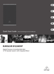
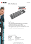
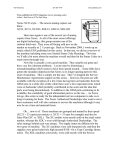
A Service Excellence Publication…
WC 4150 style
(WorkCentre 4150c, 4150s, 4150x, 4150xf, 4250, 4260)
www.partsdrop.com
TECHNICAL INFORMATION
*All model names are trademarks of Xerox Corporation
4150 - Shown without
Finisher option.
Machine Intro (excerpt from ENX Magazine article June 2008)
The 4150 model machines are small and fast… They boast 45 pages per minute
black and white. They start at around $2200.- for the 4150c which serves only as a
copier. Add another $200.- and upgrade to the 4150s which adds printing, scan to email
and network printing capabilities (with fax as an option). The most costly option is the
4150xf which comes with extra paper decks (4 all together), a stand and a Finisher (the
finisher fits into the empty area in the center of the machine which otherwise serves as
the catch tray area). The Duplex feature and the Duplexing Automatic Document
Feeders (DADF) are standard features on all models. Xerox Dealerships who have been
placing these machines and servicing them have told me on a few occasions now that
they are very reliable machines with few inherent problems. One of the good dogs.
The newer models are WC-4250 and 4260. Many similarities but also some
differences will be found.
These machines are built to make the primary consumables easy to replace. The
Fuser Module was a case-in-point… a few screws and it’s out. Other stuff will likely
prove to be not-so-friendly… but time will tell.
The main consumables are the Toner Cartridge and the Drum Cartridge (or
“Xerographic Module” as the manual calls it). Interestingly the Developing station is
actually inside the Drum Cartridge… so the Toner Cartridge is really just a supplier of
the toner to the Drum Cartridge. The waste container is on the front of the Toner
Cartridge
The Toner Cartridge is initially provided to machines under OEM contract under
the part number 6R1274 (that is the “Metered plan” version)… once a machine is taken
off of contract, the consumables are then changed over to the “sold” plan. In North
America and Europe, the reorder number for the “Sold plan” version is 6R1275 and in the
Developing Market Operations West (DMO West), the part number will be 6R1276
instead. The Toner Cartridge is supposed to yield 20K pages at 5% coverage… it sells
for around $120.-. The machine does have a sensor which senses when the toner material
is actually running low, but it also has a counter chip on the unit which will terminate at
20K pages if the toner does not run out first.
The chips or “CRUM”s (Customer Replaceable Unit Monitor) on both cartridges
are the new RF (Radio Frequency) type of technology. In this case, the “chip” is a very
slim piece which looks more like a fancy sticker adhered to the side of the cartridge.
Eventually someone will need to start producing replacements for these CRUM stickers.
It may be a little wait before replaceable CRUMs are available in the market because,
while there is rumor of soon to be released RF chips for other models, this one is unique
so far in form.
The Xerographic Module (Drum Cartridge) sells for $280.- under the part number
013R00623. It is rated for 55K pages.
Page 1 of 10
Thanks goes to ENX Magazine for first publishing the series of articles for which these pages were first compiled. www.enxmag.com
*All models numbers are trademarks of Xerox Corporation. Xerox is in no way affiliated with these pages.
A Service Excellence Publication.
www.partsdrop.com
Now let’s get into the Fault Codes and their meanings. The list which follows is
abbreviated somewhat but should give you an idea where to start looking.
If you get calls about fault messages rather than Fault Codes on the screen… have
the customer press the “Machine Status” button to view the Fault Codes so you’ll have a
better idea what the problem is. It may be necessary to have them enter the “Customer
Tools” menus to get more information. Here’s how that is done:
Press the “Access” button and enter the password (the default is ‘1111’ on this
machine). Then touch the “Go to Tools” button. You’ll find a well laid out menu with
all sorts of customizable features and adjustable defaults including the customer version
of the Supplies Management and a Fault History.
FAULT / STATUS CODES:
Code:
Description
01-100
Right side door open.
01-200/300/400
Tray 2 / 3 / 4 access door open.
01-500
Finisher front door open.
03-xxx Codes
Communication and Software faults.
04-100
Tray 1 Elevator troubles.
04-200/300/400
Tray 2 / 3 / 4 elevator problems.
04-500
Main Motor drive problem (often something is bound up and
keeping the motor from turning).
04-800
Duplex Fan failure.
04-910
Power Supply Fan failure.
05-100 thru 900
Document Feeder (DADF) jams.
05-920
Document Feeder top cover / door interlock open.
05-930
Document Feeder exit door interlock open.
06-100/200
Laser Unit (LSU) errors.
07-xxx
Paper Supply problems such as tray interlocks open or paper
supply low or empty.
08-xxx
Paper jams.
09-100
Toner low.
09-200
Toner empty condition sensed.
09-210
Toner sensing problem.
09-220
Toner Count is expired (the CRUM’s counter is up). Replace the
Toner Cartridge to reset.
09-230/240/250/500 Problems with the Toner Ctg. CRUM (Customer Replaceable
Unit Monitor) / Radio Frequency (RF) chip.
09-300
Drum warning (new end of 55K life)
09-310
Drum cartridge drum is not turning properly. (check the drum and
the drives to the drum’s drive coupling)
09-320/330/340/600 Drum Cartridge CRUM (chip) failure.
09-400
Drum Cartridge end of life.
09-700
Toner supply error (Toner is not making it from the toner
cartridge to the xerographic module / drum ctg.)
For Parts & Supplies visit us at www.partsdrop.com
or Call: 201-387-7776
Page 2 of 10
A Service Excellence Publication.
www.partsdrop.com
09-800
09-900
10-100/200
10-300
10-400
12-100/200/300/400
12-500
12-600/610
12-700
12-710/720
12-730
12-740
12-750
12-760
14-100
Wrong Toner Cartridge detected (incompatible CRUM chip)
Wrong Xerographic Module (Drum Ctg.) (incompatible CRUM
chip)
Low fuser temperature detected.
Fuser Overheat problem.
Fuser fault (the manual is not all that specific on this code).
Finisher jams.
Finisher exit tray is full.
Stapler problems.
Finisher compiler paddle fault.
Finisher jogger faults.
Finisher support finger home sensor fault.
Finisher ejector failure.
Finisher stapler fault.
Finisher stacker fault
CCD / Scanner carriage is locked. Check the slide latch which is
designed to be used during shipping… It’s located underneath the
Scanner Bed, just above where the paper exit tray is found.
Some of the codes or messages require resetting a counter in diagnostics (read about
“Resetting the HFSI Counters” (High Frequency Service Item Counters) later on page 5).
System Administrator Tools (user menu):
For setting up machine defaults and options which are available to the customer,
you’d want to go into the “System Administration Tools”. This is done by pressing the
‘Access’ button and entering the Administrator’s Password (‘1111’ is the Default
password). Then touch “Go To Tools”. You’ll find a bunch of stuff in an easy to
navigate menu:
• System Settings
• Feature Defaults
• Screen Defaults
• Connectivity / Network Settings
• Access and Accounting
• Online / Offline
• Supplies Management
• Machine Tests
• Customer Support and Supplies Number
• Power Saver Administration
• Optional Services
• Software Reset
• Customer Software Upgrade
• Fax Setups
• On Demand Image Overwrite
For Parts & Supplies visit us at www.partsdrop.com
or Call: 201-387-7776
Page 3 of 10
A Service Excellence Publication.
www.partsdrop.com
System Settings gives you access to things like telling the machine if you want it
to run a Configuration Report or not, each time the power is turned on.
Supplies Management is a particularly interesting menu item. Here you (or the
customer for that matter) can reset the Counters for the Fuser, BTR (Bias Transfer Roll),
and Feed Rollers. They also have options in there to Enable or Disable the Drum
Cartridge or Toner Cartridge Status. If the Service Manual is correct, then the Fuser can
be reset from here… if that fails, you can enter Diagnostic Mode and choose “HFSI”
(High Frequency Service Items) and reset it from there (read more later in this article.
Machine Tests includes some Image Quality Test Patterns which could come in
handy when troubleshooting copy quality problems.
Entering Diagnostic Mode:
Hold down the ‘#’ key while then pressing the ‘Access’ key. You’ll get a
Diagnostic Login Window. Enter the password followed by ‘Enter’ (the default
password is ‘1934’). Note that if you accidentally enter the wrong password 3 times in a
row, the machine will lock-up for 3 minutes before you can try again.
When you are done in the Diagnostics, you will want to exit by pressing the “Call
Closeout” button. You’ll want to choose to reboot the copier if you have made any
changes to memory settings.
Once in Diagnostics, you’ll find the Main Menu:
Main Diagnostics Menu:
• Service Info - Here you’ll find the HFSI (High Frequency Service Items) Resets.
Also you can read the machine’s Network IP Address and the System
Administrator’s Password.
• Fault History - Check the Fault Log to see what is going on with the machine.
• Diagnostic Routines - If you touch this Tab, you’ll find a submenu:
- Copier Routines
- Network Routines
- Fax dC Routines
- Other Routines
In the “Copier Routines” (Diagnostic Routines / Copier Routines), you will find yet
another juicy submenu including dC131 NVM Read / Write (Non Volatile Memory
adjustments), and dC330 Component Control for testing motors, sensors and such. We’ll
go through the test codes and memory codes later on.
“Other Routines” (Diagnostic Routines / Other Routines), you’ll find the “Shading Test”
which allows you to check the functionality of the CCD (Charge Coupled Device… the
electronic part up top on the exposure carriage which scans the originals). You’ll also
find the following functions:
For Parts & Supplies visit us at www.partsdrop.com
or Call: 201-387-7776
Page 4 of 10
A Service Excellence Publication.
www.partsdrop.com
dC001 Reset Auditron Master PIN. This resets the Administrator’s Password (default
is ‘1111’). The Auditron Master and Administrator share the same password (two hats
for one person I suppose?).
dC606 Print Test Patterns, and the “Shading Test” which allows you to check the
functionality of the CCD (Charge Coupled Device… the electronic part up top on the
exposure carriage which scans the originals).
Resetting HFSI Counters (High Frequency Service Item Counters) … for example the
Fuser Count: This is done by first entering Diagnostic Mode as detailed below. Next
touch the ‘HFSI’ tab to bring up the HFSI Table. Look for & select the Fuser. Its status
will show either “off” (not being tracked) or “OK” if it is not over the count yet, or it’ll
say “Check” if it is over its count. To reset the fuser’s actual count to zero, select and
highlight the fuser on the list and then touch ‘Reset’ followed by ‘OK’. Now choose
‘Exit’. Touch ‘Call Closeout’. From this screen, leave “Reboot Copier” set to “yes” so
that your HFSI Fuser counter will be properly reset during the rebooting process.
Component Control:
Now let’s get some details on how to test various parts of the machine. Enter
Diagnostic Mode, then touch “Diagnostic Routines”, followed by “Copier Routines” and
finally “330 Component Control”. From here you can enter the “Chain – Function”
codes (the ’Chain’ is the first two digits before the dash, and the ‘Function’ is the 3 digits
after the dash)… or you can browse through the available codes by pressing the button
which says “Find Component’. Find and touch the component you want to try out and
press ‘Select’ to add that component to the top of a short list of up to 6 components which
they call the “Component Name Table List”. If you choose more than 6, the bottom one
on the list will get removed from the list. Each of the components on the short list of
readied codes will have their status shown as either “On”, “Off”, “High”, or “Low”. To
actually energize one of your readied codes, touch the code to highlight it and press
‘Start’. To then stop a component’s test, touch the code and then touch ‘Stop’.
Even though the lists are available in a menu form, it may be helpful to have a list of the
codes in front of you to save you some hunting time. Below are the codes which are
most likely to be useful. They are broken down into the “Input Codes” (switches and
sensors) and the “Output Codes” (motors, fans, solenoids, & clutches).
Input Component Codes: (abbreviated list):
01-100
Right Side Cover Interlock
“Opened “ = Cover is open.
01-200
Exit Cover Present Sensor
“Closed” = Exit Cover is installed.
04-110
Main BLDC Motor
“High” = Running at normal speed.
“Low” = Not running at normal speed.
04-410
Duplex Fan 1 Speed
“High” = Running at normal speed.
“Low” = Not running at normal speed.
04-420
Duplex Fan 2 Speed
“High” = Running at normal speed.
“Low” = Not running at normal speed.
05-xxx
DADF (Document Feeder) test
Codes
codes:
05-100
Document Detect Sensor
“High” = Document sensed.
“Low” = No Document sensed.
For Parts & Supplies visit us at www.partsdrop.com
or Call: 201-387-7776
Page 5 of 10
A Service Excellence Publication.
www.partsdrop.com
05-110
05-120
05-130
05-140
05-150
05-160
05-170
05-180
05-400
06-110
Document Paper Width Sensor
Document Paper Length Sensor
Document Registration Sensor
Document Scan Sensor
Document Geate Sensor
Document Door Open Switch
Document Duplex Sensor
Document Exit Door Open
Sensor
Document Platen Cover Switch
Laser Unit Motor Ready
06-310
Laser Unit Fan Ready
07-100/200/
300/400
07-110/210/
300/400
07-120/220/
320/420
07-130/230/
330/430
07-140/240/
340/440
07-150/250/
350/450
07-160/260/
360/460
07-510
08-100/200
300/400
08-500
08-600
08-700
08-710
08-720
09-110
Tray 1/2/3/4 Tray Home Sensor
09-310
09-510
09-700
10-200
“High” = Sensor is actuated.
“High” = Document sensed.
“High” = Document sensed.
“High” = Document sensed.
“High” = Document sensed in gate.
“High” = Door open.
“High” = Document present.
“High” = Door open.
Tray 1/2/3/4 Paper Empty Sensor
“High” = Platen is raised.
“High” = Laser Motor is running at
normal speed.
“High” = Laser Unit Cooling Fan is
running at normal speed.
“Low” = Tray is detected in home
position.
“High” = Tray is empty.
Tray 1/2/3/4 Size Sensor 1
“High” = Sensor is actuated.
Tray 1/2/3/4 Size Sensor 2
“High” = Sensor is actuated.
Tray 1/2/3/4 Size Sensor 3
“High” = Sensor is actuated.
Tray 1/2/3/4 Stack Height Sensor “High” = Paper in tray is elevated.
Tray 1/2/3/4 Paper Low Sensor
“High” = Paper in tray is low.
Bypass Paper Empty Sensor
Tray 1/2/3/4 Feed Sensor
“High” = Bypass Tray empty.
“High” = Paper present at appropriate
tray’s sensor.
Registration Sensor
“High” = Paper sensed at Reg. Sensor.
Exit Sensor
“High” = Paper sensed at Exit Sensor.
Duplex Jam 1 Sensor
“High” = Paper sensed at sensor.
Duplex Jam 2 Sensor
“High” = Paper sensed at sensor.
Out-Bin Full Sensor
“High” = Paper full detected.
MHV (Main High Voltage) Bias Display shows the Main (charge) High
Read
Voltage value.
THV (Transfer High Voltage)
Display shows the Transfer Roll’s High
Bias Read
Voltage value.
SMPS (Power Supply) Fan check “High” = SMPS Fan is running at normal
speed.
Toner Sensor
Display shows the toner level value.
Fuser Temperature at Thermistor Display shows temperature in degrees
For Parts & Supplies visit us at www.partsdrop.com
or Call: 201-387-7776
Page 6 of 10
A Service Excellence Publication.
www.partsdrop.com
10-210
10-300
10-510
12-xxx
Codes
‘A’
Fuser Temperature at Thermistor
‘B’
Fuser Unit Fault detected.
Fuser Fan ready test.
Codes which relate to the
optional Finisher.
Celsius (C = XXX)
Display shows temperature in degrees
Celsius (C = XXX)
Display shows either “Normal” or “Fault”
“High” = Fan is running at normal speed.
Output Component Codes: (Motors, Fans, Clutches & Solenoids)
04-100
Main Motor
04-200
Exit Motor –Forward Fast
04-210
Exit Motor – Forward Slow
04-300
Duplex Motor – Forward
04-310
Duplex Motor – Backward
04-400
Duplex Fan 1 & 2
04-510
Tray 1 Elevator Motor – Up
04-520
Tray 2 Elevator Motor – Up
04-530
Tray 3 Elevator Motor – Up
04-540
Tray 4 Elevator Motor – Up
05-200
Document Scan Motor – Forward
05-210
Document Duplex Motor – Forward
05-220
Document Duplex Motor – Backward
05-300
Document Pick-up Clutch
05-310
Document Registration Clutch
08-800
Bypass Feed Clutch
08-810
Tray 1 Feed Clutch
08-820
Tray 2 Feed Clutch
08-830
Tray 3 Feed Clutch
08-840
Tray 4 Feed Clutch
08-850
Registration Clutch
08-860
Duplex Feed Clutch
08-870
Duplex Gate Solenoid
08-920
Tray 2 Feed Motor
08-930
Tray 3 Feed Motor
08-940
Tray 4 Feed Motor
09-100
MHV (Charge Voltage)
09-200
Developer Bias
09-300
THV (+) (Positive Transfer Voltage)
09-400
THV (-) (Negative Transfer Voltage)
09-500
SMPS Fan (Power Supply Fan)
09-600
Toner Dispense Motor
09-800
Detack Bias Voltage
10-100
Fuser Power On
For Parts & Supplies visit us at www.partsdrop.com
or Call: 201-387-7776
Page 7 of 10
A Service Excellence Publication.
www.partsdrop.com
10-400
10-500
10-600
12-XXX
Codes
20-XXX
Codes
Fuser Motor – Forward
Fuser Fan
Fuser Bias Voltage.
Codes which relate to the optional Finisher.
Fax output signal test codes for testing the fax
modem’s various bps signals.
NVM Read / Write (Non Volatile Memory Settings & Adjustments):
The Memory settings or “NVM Read / Write” (Non Volatile Memory) are found in the
“Copier Routines”. Enter Diagnostic Mode, then touch “Diagnostic Routines”, followed
by “Copier Routines” and then “131 NVM Read / Write”. Once you are in there you’ll
touch the appropriate “Chain” button (the chain is the first 2 digit part of the code). Then
scroll through the choices and touch the code you want followed by “Read/Write”. That
will open the “Read/Write” window where you can change the value and save it. If you
touch “Reset”, the selected code will return to its default value. Some of the codes are
“Read Only” and some require a password which would need to be gotten from Xerox
directly in order to change the setting.
We will start with just the Registration Codes (there are quite a few of these, so we’ve
condensed them to save space a bit) All of the Registration Codes use “30” as the default
and have ranges of 0-60 with every 13 steps resulting in a change of 0.5mm.
Registration for DADF (Doc Feeder) & Platen (scanning)…
05-100 : DADF Top Edge Erase
(Single sided)
05-110 : DADF Bottom Edge Erase
(Single sided)
05-120 : DADF Left Edge Erase
(Single Sided)
05-130 : DADF Right Edge Erase
(Single sided)
05-310 : DADF Bottom Edge Erase
(Duplex)
05-410 : DADF Horizontal
Magnification (Duplex)
05-520 : Platen Left Edge Erase
05-210 : DADF Horizontal
Magnification (Single Sided)
05-320 : DADF Left Edge Erase
(Duplex)
05-500 : Platen Top Edge Erase
05-300 : DADF Top Edge Erase
(Duplex)
05-330 : DADF Right Edge Erase
(Duplex)
05-510 : Platen Bottom Edge Erase
05-530 : Platen Right Edge Erase
05-610 : Platen Horizontal
Magnification
06-100 : Vertical Magnification
06-110 : Horizontal Magnification
07-100 : Tray 1 – Top Registration
(Single sided)
07-110 : Tray 1 – Side Registration
(Single sided)
07-120 : Tray 1 - Top Registration
(Duplex 2nd side)
07-130 : Tray 1 – Side Registration
(Duplex 2nd side)
07-140 : Tray 1 – Top Registration
(Duplex 1st side)
07-150 : Tray 1 – Side Registration
(Duplex 1st side)
07-200 : Tray 2 – Top Registration
(Single sided)
07-210 : Tray 2 – Side Registration
(Single sided)
07-220 : Tray 2 – Top Registration
(Duplex 2nd side)
07-230 : Tray 2 – Side Registration
(Duplex 2nd side)
07-240 : Tray 2 – Top Registration
(Duplex 1st side)
07-250 : Tray 2 – Side Registration
(Duplex 1st side)
07-300 : Tray 3 - Top Registration
(Single sided)
07-310 : Tray 3 – Side Registration
(Single sided)
07-320 : Tray 3 – Top Registration
(Duplex 2nd side)
07-330 : Tray 3 – Side Registration
(Duplex 2nd side)
Registration for Trays:
For Parts & Supplies visit us at www.partsdrop.com
or Call: 201-387-7776
Page 8 of 10
A Service Excellence Publication.
www.partsdrop.com
07-340 : Tray 3 – Top Registration
(Duplex 1st side)
07-350 : Tray 3 – Side Registration
(Duplex 1st side)
07-400 : Tray 4 – Top Registration
(Single sided)
07-410 : Tray 4 – Side Registration
(Single sided)
07-420 : Tray 4 – Top Registration
(Duplex 2nd side)
07-430 : Tray 4 – Side Registration
(Duplex 2nd side)
07-440 : Tray 4 – Top Registration
(Duplex 1st side)
07-450 : Tray 4 – Side Registration
(Duplex 1st side)
07-500 : Bypass – Top Registration
(Single sided)
07-510 : Bypass – Side Registration
(Single sided)
07-520 : Bypass – Top Registration
(Duplex 2nd side)
07-530 : Bypass – Side Registration
(Duplex 2nd side)
07-540 : Bypass – Top Registration
(Duplex 1st side)
07-550 : Bypass – Side Registration
(Duplex 1st side)
NVM Read / Write (Continued):
Code
05-700
05-710
08-100
08-110
08-120
08-130
08-140
08-150
08-160
09-100
09-110
09-120
09-130
09-140
09-200
09-210
09-230
10-100
10-105
10-110
10-115
10-120
Name / Description
Document Roller Page Counter
Document Retard Pad Page Counter
Tray 1 Nudger (Pickup) Roller Page Counter
Tray 1 Feed Roller Page Counter
Tray 1 Retard Roller Page Counter
Tray 2 Nudger (Pickup) Roller Page Counter
Tray 3 Nudger (Pickup) Roller Page Counter
Tray 4 Nudger (Pickup) Roller Page Counter
Bypass Retard Pad Page Counter
Laser Light Level (600dpi value in PWM)
Main Charge Bias Control (value in PWM)
Transfer Bias Control (THV) (value in PWM)
Developer Bias Control (standard voltage =
-500V (PWM 522)
Detack Bias Control (standard voltage =
-1800V)
Drum Page Counter
Toner Page Counter
Transfer Roll Counter
Fuser Standby temperature (target) (4 steps =
5 degree interval)
Fuser Run Temmerature (target) (3 steps =
5 degree interval)
Fuser Power Save Mode Temperature (9 steps =
5 degree interval)
Fuser Wide Paper (101-185mm) Temperature
(offset temperature on Thermistor B) (4 steps =
5 degree interval)
Fuser Wide Paper (186-216mm) Temperature
(offset temperature on Thermistor B) (4 steps =
Value / (default)
Read Only
Read Only
Read Only
Read Only
Read Only
Read Only
Read Only
Read Only
Read Only
200-600 (default = 350)
108-145 (default = 126)
41-220 (default = 76)
408-607 (default = 522
80-160 (default = 123)
Read Only
Read Only
Read Only
0-15 (default = 10
0-10 (default = 5)
0-40 (default = 20)
0-15 (default = 5)
0-15 (default = 5)
For Parts & Supplies visit us at www.partsdrop.com
or Call: 201-387-7776
Page 9 of 10
A Service Excellence Publication.
www.partsdrop.com
10-125
10-130
10-135
10-140
10-145
10-150
10-155
10-200
10-210
10-220
10-300
10-310
5 degree interval)
Fuser Heavy Paper (60gms) Temperature
(offset temperature) (4 steps =
5 degree interval)
Fuser Very Heavy Paper (90gms) Temperature
(offset temperature for heavy media) (3 steps =
5 degree interval)
Fuser Bond Paper Temperature Offset
Fuser Transparency Temperature Offset
Fuser Cardstock Temperature Offset
Fuser Envelopes Temperature Offset
Fuser Labels Temperature Offset
Fuser Assembly Page Counter
Fuser Heat Roll Page Counter
Fuser Pressure Roll Page Counter
Fuser Temperature Pickup Interval Delay (in
microseconds)
Fuser Temperature Pickup Interval Delay for
Special Papers (in microseconds)
0-15 (default = 5)
0-10 (default = 5)
0-10 (default = 5)
0-10 (default = 5)
0-10 (default = 5)
0-10 (default = 5)
0-10 (default = 5)
Read Only
Read Only
Read Only
0-100 (default = 0)
0-100 (default = 0)
The Service Manual mentions that it is not possible to read or modify any NVM
which contains customer administrator data. This means that some things which are
traditionally adjusted or readable from the NVM Read / Write may actually need to be
accomplished from the Administrator Tools … The exception is the resetting of the
Administrator’s PIN (dC 001 … see page 5).
Author: Britt Horvat
Published originally in Article form by ENX Magazine. A list of articles about Xerox
equipment can be found on their website (www.enxmag.com) if you look up Contributing
Authors and scroll down till you see Britt’s mug.
For Parts & Supplies visit us at www.partsdrop.com
or Call: 201-387-7776
Page 10 of 10