1
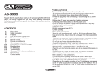
32” HD-LCD TV/DVD Combo with High Definition ATSC Tuner
FXM-3211C, FXX-321C
SERVICE MANUAL
20060811
Important Service and Safety Information
Prior to using this service manual, please ensure that you have carefully
followed all the procedures outlined in the user's manual for this product.
(1)
Read all of these instructions.
(2)
Save these instructions.
(3)
Follow all warnings and instructions marked on the product.
(4)
Unplug this product from the wall outlet before cleaning. Do not use liquid cleaners or aerosol cleaners; use a
damp cloth for cleaning.
(5)
Do not use this product near water.
(6)
Do not place this product on an unstable cart, stand or table. The product may fall, causing serious damage to the
product.
(7)
Slots and openings in the cabinet and the back or bottom are provided for ventilation, to ensure reliable operation
of the product and to protect it from overheating, those openings must not be blocked or covered. The openings
should never be blocked by placing the product on a bed, sofa, rug, or other similar surface. This product should
not be placed in a built-in installation unless proper ventilation is provided.
(8)
This product should be operated from the type of power source indicated on the marketing label. If you are not
sure of the type of power available, consult your dealer or local power company.
(9)
This product is equipped with a 3-wire grounding type plug, a plug having a third (grounding) pin. This plug will
only fit into a grounding-type power outlet. This is a safety feature, if you are unable to insert the plug into the
outlet, contact your electrician to replace your obsolete outlet. Do not ignore the purpose of the grounding-type
plug.
(10) Do not allow anything to rest on the power cord. Do not locate this product where people will walk on the cord.
(11) If an extension cord is used with this product, make sure that the total of the ampere ratings on the product
plugged into the extension cord does not exceed 15 ampere.
(12) Never push objects of any kind into this product through cabinet slots as they may touch dangerous voltage points
or short out parts that could result in a risk of fire or electric shock. Never spill liquid of any kind on the product.
(13) Do not attempt to service this product yourself, as opening or removing covers may expose you to dangerous
voltage points or other risks. Refer all servicing to service personnel.
(14) Unplug this product from the wall outlet and refer servicing to qualified service personnel under the following
conditions:
a. When the power cord or plug is damaged or frayed.
b. If liquid has been spilled into the product.
c. If the product has been exposed to rain or water.
d. If the product does not operate normally, when the operating instructions are followed. Adjust only
those controls that are covered by the operating instructions since improper adjustment of other
controls may result in damage and will often require extensive work by a qualified technician to
restore the product to normal operation.
e. If the product has been dropped or the cabinet has been damaged.
f. If the product exhibits a distinct change in performance, indicating a need for service.
2
Important Service and Safety Information
Service work should be performed only by qualified service technicians familiar with all safety
checks and these service guidelines:
ELECTRIC SHOCK HAZARD
Always disconnect AC power before servicing!
Never modify any circuit!
Never insert any objects into the holes in the TV case!
ELECTROSTATIC DISCHARGE (ESD)
Components inside an LCD or plasma TV are sensitive to static electricity. Before servicing the TV, follow these
guidelines:
•
•
•
•
•
Avoid static-causing surfaces such as carpeted floors, plastic, and packing foam.
Remove replacement components from their antistatic bags only when you are ready to use them. Do
not lay components on the outside of antistatic bags because only the inside of the bags provide
electrostatic protection.
Always hold components by their edges. Avoid touching the edge connectors. Never slide components
over any surface.
Wear a grounding wrist strap (available at most electronics stores) and attach it to a bare metal part of
your workbench or other grounded connection.
Touch a bare metal surface on your workbench or other grounded object before touching any
components.
NOTICE ABOUT REPLACEMENT PARTS
Many electrical and mechanical parts within LCD or plasma televisions are chosen for their
specific safety characteristics within the overall system. Replacing individual parts with
components rated for higher voltage or wattage can be dangerous!
Replacement parts must always be identical to those originally used in the television. Unauthorized substitute
parts may result in fire, electric shock, or other hazards.
3
Table of Contents
1.
2.
3.
4.
5.
6.
Specifications ...................................................................................................................................... 5
Operation............................................................................................................................................ 7
Troubleshooting Flow Chart................................................................................................................ 13
Display Cell Defect Specification ......................................................................................................... 15
Before Returning This Product to the User .......................................................................................... 16
Disassembly Procedure ...................................................................................................................... 17
Rear Cover Removal...................................................................................................................... 18
Main Board Removal and Replacement ........................................................................................... 20
Control Button Board Removal and Replacement............................................................................. 22
DVD Module Board Removal and Replacement................................................................................ 23
Power Board Removal and Replacement ......................................................................................... 24
IR / Power LED Board Removal and Replacement ........................................................................... 25
7. Spare Parts List – FXM-3211C, FXX-321C ............................................................................................ 26
8. Exploded View Diagram – FXM-3211C, FXX-321C ................................................................................ 27
9. Block Diagrams – FXM-3211C, FXX-321C ............................................................................................ 28
10. Schematic Diagrams – FXM-3211C, FXX-321C ..................................................................................... 30
11. PCB Layout Diagrams ........................................................................................................................ 38
4
1.
Specifications
FXM-3211C, FXX-321C Specifications:
TFT-LCD Resolution
1366x768
TFT-LCD Screen Size
31.5 inches
Laser Wavelength
780/650 nm
Video System
NTSC
Frequency Response
20Hz-20kHz
Audio Signal-to-noise Ratio
≥85dB
Audio distortion + noise
≤70dB (1kHz)
Channel Separation
≥70dB (1kHz)
Dynamic Range
≥80dB (1kHz)
±2.5dB
0.2
Audio Out
Analog Audio Out
Out Level: 1.5V±1.0 , Load: 10KΩ
Video Out
Video Out
Out Level: 1VP-P±0.1, Load: 75Ω
Unbalanced Negative
Power
AC110-220V 50/60Hz
Power Consumption
<230W
Ambient Temperature
10—45˚C (50—113˚F)
DESIGN AND SPECIFICATIONS ARE SUBJECT TO CHANGE WITHOUT NOTICE
5
Discs Formats Supported By This Player:
DISC LOGO
•
•
CONTENTS
SIZE
DVD
Audio + Video
(movies)
12cm
CD
Audio
12cm
JPEG
Still Photographs
12cm
MAXIMUM TIME
133min(SS-SL)
242min(SS-DL)
266min(DS-SL)
484min(DS-DL)
74min
The operating method of some DVD discs is specified by the software maker. Please refer to the
instruction manual of the disc.
The DVD Player will play most recordable (CD-R) or erasable (CD-RW) CDs, but playback of CD-R or
CD-RW discs created on a computer requires proper formatting and finalization of the disc for audio
playback. Some computers and/or software programs may not be capable of creating compatible
discs.
6
2.
Operation
Front and Right View:
(1)
31.5" Color TFT screen - Offers a crystal clear image.
(2)
INPUT button - Press to enter the Input menu and then use the buttons to select mode: Tuner, AV1
(Composite 1), AV2 (Composite 2), AV3 (Component 1), AV4 (Component), VGA, HDMI, DVD, then press the Enter
button to enter the selected mode.
(3)
MENU button - Press to enter or exit system setup menu.
(4)
CH ▲/▼button - In TV mode, press to select channels. In setup menu, the same function as ▲/▼ direction
buttons.
(5)
VOL ▲/▼ button - Press to decrease or increase the volume, the same function as ◄/► direction buttons in setup
menu.
(6)
STOP button - Press to stop playback in DVD mode.
(7)
PLAY button - Press to start playback in DVD mode.
(8)
EJECT button - Press to eject the disc out from the disc tray.
(9)
POWER button - Press to enter or exit the standby mode.
(10) Disc Tray Slot - Insert disc into this slot.
(11) SD/MS/MMC card port - Insert SD/MS/MMC card into this slot.
(12) USB Port - Connecting to the USB device.
(13) Remote Sensor - Remote sensor window for the remote control.
(14) Power Indicator - In standby mode, it turns red; when operation it is blue;
(15) Speakers - Provides high quality sound.
7
Rear View:
(1)
Y/Pr(Cr)/Pb(Cb) and L/R audio Input Jacks - Connectors
for the Y/Pr(Cr)/Pb(Cb) input in AV3 (Component) mode.
(2)
Y/Pr(Cr)/Pb(Cb) and L/R audio Input Jacks - Connectors
for the Y/Pr(Cr)/Pb(Cb) input in AV4 (Component) mode.
(3)
Video and L/R audio Input Jacks - Connectors for the
audio and video signal input in AV1 (Composite) mode.
(4)
Video/S-VIDEO and L/R audio Input Jacks - Connectors
for the audio and video/S-Video signal input in AV2
(Composite) mode. The Video and S-Video is with the
same L/R audio jacks, and the S-Video is the priority.
(5)
Earphone Jack - Used for connecting to the earphone.
(6)
TV Signal Input Jack - Connect to TV antenna in TV
mode.
(7)
VGA Input Jack - Connect to the VGA output jack of the
PC in VGA mode.
(8)
HDMI Jack - Connect to the HDMI.
(9)
OPTICAL audio output Jack - Connectors for the optical
digital audio (SPDIF) output.
(10) AV Output Jack - Connectors for the audio and video
signal output.
(11) Power In Jack - Connect to power supply.
8
Remote Control – General:
Using Remote control
Point the remote control no more than 7 meters from
the remote control sensor and within about 60
degrees of the front of the unit.
Installing Batteries
Push the back cover to open the battery
compartment.
Insert two batteries (1.5V, size AAA), please make
sure the polarity matches the marks inside the
compartment.
Press the back cover to close it.
The operating distance may vary depending on the
surrounding brightness.
Under normal use the batteries will last for six
months. Remove the batteries when the remote will
not be used for a long time.
Notes:
• Do not point bright lights directly at the remote
control sensor.
• Do not place objects between the remote
control unit and the remote control sensor.
• Do not use this remote control while
simultaneously operating the remote control of
any other equipment.
9
Remote Control – TV Mode:
(1)
POWER button - Press to enter or exit the standby
mode.
(2)
0~9 Number buttons - Press to select numbers.
(3)
MTS button - In TV mode, press to shift among SAP,
Mono or Stereo mode.
(4)
VOL +/- button - Press to increase or decrease the
volume.
(5)
MUTE button - Press to turn on or off the speaker
output.
(6)
Input button - Press to enter the Input menu, then use
the▲▼button to select mode: Tuner, AV1 (Composite),
AV2 (Composite), AV3 (Component), AV4 (Component),
VGA, HDMI, DVD, press the Enter button to enter the
selected mode.
(7)
Direction buttons (▲▼◄►) - In the setup menu,
press the ▲▼button to select the desired items, press
the ◄► button to adjust or set.
(8)
Enter button - Press to confirm selection or exit the
setup in the setup menu.
(9)
Sleep button - press to set the sleep time.
(10) TV button - Press to shift to TV mode.
(11) Signal button - Press to display the ATSC signal status.
(12)
button - Press number buttons to select channel and
then press the button to confirm and go the selected
channel.
(13) +10/- button - In TV mode, press the number buttons
to select channel first, then press this button and add
number button “0” or one number from “1~5” to select
analog or digital TV program. Add “0” for analog TV
program, add one number from “1~5” for digital TV
program.
(14) Last button - In TV mode, press to return to the
channel last viewed.
(15) CH /button - In TV mode, press to select channel.
(16) Freeze button - Press to freeze the current picture.
(17) Menu button - Press to enter or exit the system setup
menu.
(18) Exit button - Press to exit system setup menu.
(19) CC button - Press to display among CC1, CC2, CC3, CC4
or CCD function OFF.
(20) Info. Button - Press to display the current mode
information on the screen.
10
Remote Control – DVD Mode:
(1)
Play button - Press to play the disc in DVD mode.
(2)
Pause button - In DVD mode, press to pause the
playback or start step frame by frame playback. Press the
PLAY button to resume normal playback.
(3)
Fast Reverse button - In DVD mode, press to search
backward
(4)
Fast Forward button - In DVD mode, press to search
forward.
(5)
0~9 Number buttons - Press to select numbers.
(6)
Direction buttons (▲▼◄►) - In the setup menu, press the
▲▼button to select the desired items, press the ◄► button
to adjust or set.
(7)
Enter button - Press to confirm selection or exit the setup in
the setup menu.
(8)
Audio button - In DVD mode, press to select audio language
when the DVD disc with multiple audio languages is played.
(9)
Angle button - In DVD mode, press to select various
camera angles (if the DVD disc contains multiple camera
angles).
(10) DVD menu button - Press to access the disc menu in DVD
mode.
(11) Setup button - Press to access the DVD setup menu under
DVD mode.
(12)
Eject button - Press to eject the disc out.
(13) ■ Stop button - In DVD mode, press to stop playback, then
press the PLAY button to resume normal playback. Press the
STOP button twice repeatedly to stop completely.
(14) Next Skip button - Press to skip to the next chapter/track
for some discs under DVD mode.
(15) Previous Skip button - Press once to skip to the
beginning of the current chapter/track. Press twice repeatedly
to skip to the previous chapter/track for some discs under DVD
mode.
(16) +10/- button - Press the button and 0~9 number buttons to
select number greater than 9.
(17) Card button - In DVD mode, press to shift to USB or CARD
mode when there is the input source.
(18) Title button - In DVD mode, during a DVD disc playback,
press to go to title menu if the disc contains.
(19) Subtitle button - In DVD mode, press to select different
subtitle languages during a multiple language DVD disc
playback.
(20) Repeat button - In DVD mode, press to repeat a chapter,
track, title, or all content
11
Moving the DVD Disc Tray:
CAUTION: Before removing or installing the DVD disc tray, unplug the power supply cord.
This unit is designed with a movable DVD Disc Tray. The Disc Tray can be installed in three different positions
giving you the ability to maximize space and convenience. Follow the procedure (below) to remove and
reinstall.
Remove the DVD Disc Tray:
Step 1:
Open the back cover by sliding the left rear panel of the unit outward.
Step 2:
Remove the DVD disc tray.
• Loosen and remove the screw holding the DVD disc tray in place.
• Disconnect the MGI connecting cord from the LCD TV and DVD disc tray.
• Remove the DVD disc tray by pushing it outward.
Step 3:
Close the back cover.
Installing the DVD Disc Tray:
There are three different positions for installing the DVD disc tray and two MGI jacks for connecting the MGI
connecting cord.
NOTE: The bottom DVD disc tray position (3) is designed for TVs that are wall-mounted. If you
would like to install the DVD disc tray in the bottom position (3), remove the stand. To remove
the stand, cover the screen with a soft cloth and place the LCD screen face down on a stable
surface. Remove the screws securing the stand to the TV. (VESA 200 wall-mounting kit and
instructions are not included.)
Step 1:
Step 2:
Step 3:
Open the back cover on the left rear panel of the unit and select which of the three possible
positions you would like to install your DVD disc tray in.
Insert the DVD disc tray and lock into place using the screw. Plug one end of the MGI connecting
cord into the DVD disc tray. Plug the other end of the MGI connecting cord into the MGI jack on
the LCD TV.
Close the back cover.
12
3.
Troubleshooting Flow Chart
START
Power on
Does LED
change color?
N
1. Check connection between Power Board and Main Board
2. Check Power Board output voltage
Y
Does Backlight
power on?
N
1. Check connection between Power Board and LCD Module
2. Check Main Board J32 Backlight Control
Y
Does OSD
appear?
N
1. Check LVDS connector
Y
N
Does Remote
Control work?
1. Check connection between Remote Board and Main Board
2. Check ATMAGE8 pin 23
3. Check the remote receiver and transfer circuit
Y
Does the TV
display signals?
N
Y
Does sound
play as
expected?
N
1. For Tuner sources, verify the cable has signal and has a
good connection to the TV
2. For other sources, check the jack for damage
3. Check switch chip FSAV330, FSAV331 relevant circuit
4. For Y/Pb/Pr, RGB, Y/C check MST9883 signal output and
input circuit
1.
2.
3.
4.
5.
Check
Check
Check
Check
Check
cable connections including internal COAX pin
AMP TDA8932 circuit
switch chip CD4052 relevant circuit
AP8206 relevant circuit
mute control between ATMAGE8 and AMP
Y
Perform Auto
Channel Search
from the OSD
A
13
A
Do channels
save correctly?
N
1. Check CAS-220
2. Check connect circuit between tuner and CAS-220
3. Check control circuit between main chip (ZR39660) and
CAS-220
N
1. Check video and audio switch chip (FASV330/331, CD4052)
and relevant circuit
2. Check control circuit between main chip and switch chip
Y
Can you change
sources?
Y
Can you change
SRS mode?
N
Y
Does the
display look
correct?
N
NOTE: Some Inputs don’t support SRS mode
1. Check AP8206AA chip
2. Check control circuit between main chip and AP8206
1. Check filter circuit after input jacks or tuner
2. For Y/C, RGB, Y/Pb/Pr input:
Check the circuit between MST9883 and switch chip
Check the circuit between MST9883 and main chip
3. For tuner and CVBS input:
Check the circuit between switch chip and main
chip, check chip FM6408 function works correctly
Y
N
Is the sound
correct?
N
1. Check filter circuit after input jacks or tuner
2. Check the circuit between the switch chip (CD4052) and
SRS chip
3. Check the AMP functionality
Y
Have you
checked all
sources?
Y
Does AV output
work correctly?
N
1. Check FM6413 and relevant circuit
2. Check the CVBS output jack
Y
FINISH
14
4.
Display Cell Defect Specification
In some cases, a panel may have defective cells that cannot be controlled.
These defective cells can be categorized into two types;
(1)
Non-lighting or dark cell defect: defect in which the cell is always off
(2)
Non-extinguishing or bright cell defect: defect in which the cell is always on
The display cell defect specifications define the allowed limits for display cell defects and are used as the
criteria in determining whether a panel is replaced.
7 or more pixels across the entire LCD screen Polaroid will repair or replace the TV.
15
5.
Before Returning This Product to the User
Before returning this product to the user, always perform the following safety checks:
(1)
Inspect all wiring to be sure no wires are pinched between the chassis or any metal parts.
(2)
Inspect all protective devices for proper installation, including non-metallic controls, insulation materials, cabinet
backs, compartment covers, and shields.
(3)
Verify that no shock hazard exists on any part of the chassis, especially any metal components including cable
connection points, chassis hardware, or antennas (if equipped). Use the following procedure:
a. Plug the AC cord directly into a 120 V AC outlet.
b. Create a test circuit consisting of a 1.5k ohm, 10
watt resistor paralleled by a 0.15 µF capacitor.
c. Using an AC voltmeter (sensitivity of 5000 ohm per
volt or higher), measure the voltage drop across
the test circuit between all exposed metallic parts
and a known earth ground. Measurement points
include antenna, metal cabinet parts, screw heads,
and metal knobs or controls. Measurement points
can vary slightly even between revisions of the
same model, so always conduct a thorough review
of the chassis to locate metal points that a user
may touch.
d. Any voltage reading of 0.375 Vrms AC (0.25
mArms) or higher indicates a potential shock
hazard. THIS CONDITION MUST BE
CORRECTED BEFORE RETURNING THE
PRODUCT TO THE USER!
e. Repeat the above checks with the AC polarity
reversed. A non-polarized adapter is required to
reverse the polarity; DO NOT LEAVE THIS
ADAPTER WITH THE USER! Under normal
operation the product must use the proper polarity.
16
6.
Disassembly Procedure
Note: Before disassembly of any part the TV, make sure the power is OFF, and the
power cord is removed from the wall outlet. Allow time for power within all system
boards to discharge before you begin disassembly. Never insert any objects into the
vent holes in the TV case.
Note: Before returning this product to the end user, you must follow the steps
outlined in the section, Before Returning This Product to the User, on page 16. This
procedure ensures that the chassis will not cause electric shock.
When servicing an LCD or plasma TV, always observe the following safety guidelines:
•
•
•
•
•
Wear a grounding (ESD) wrist strap, and use a grounded or dissipative work mat.
Use a stable and strong work surface that is large enough to hold components you might remove.
When removing components that are attached with a cable, unplug the cable before removing the
screws to avoid damaging the cable.
Use a magnetized screwdriver for removing screws.
To help keep track of screws, place each component’s screws next to the component on your work
surface.
ELECTROSTATIC DISCHARGE (ESD)
Components inside an LCD or plasma TV are sensitive to static electricity. Before servicing the TV, follow these
guidelines:
•
•
•
•
•
Avoid static-causing surfaces such as carpeted floors, plastic, and packing foam.
Remove replacement components from their antistatic bags only when you are ready to use them. Do
not lay components on the outside of antistatic bags because only the inside of the bags provide
electrostatic protection.
Always hold components by their edges. Avoid touching the edge connectors. Never slide components
over any surface.
Wear a grounding wrist strap (available at most electronics stores) and attach it to a bare metal part of
your workbench or other grounded connection.
Touch a bare metal surface on your workbench or other grounded object before touching any
components.
17
Rear Cover Removal
(1)
Lay TV flat on workbench. Be careful to protect the front bezel and LCD screen from being scratched. Use
protective cloth between work bench and TV front.
(2)
Remove back covers A, B, and C.
A
C
B
(3)
Remove DVD Player (A), Cable (B), and Stand Cover (C).
B
C
A
18
(4)
Remove six (6) screws from the TV Stand (A) and remove the stand from the TV.
A
(5)
A
Remove all screws from the back cover (Location A).
A
A
A
(6)
Remove all screws from the rear panel label area (A) and remove back cover.
A
(7)
Remove screws from the top and bottom of the two baffles and remove the baffles.
Baffle
Baffle
19
Main Board Removal and Replacement
(1)
DVD Module Board
(2)
Power Board
(3)
Main Board
(4)
Control Button Board
(5)
Speakers
Note: Before disassembly of any part the TV, make sure the power is OFF, and the
power cord is removed from the wall outlet. Allow time for power within all system
boards to discharge before you begin disassembly. Never insert any objects into the
vent holes in the TV case.
(1)
Remove rear cover and baffles as shown in the section, Disassembly Procedure on page 17.
(2)
Remove the 4 screws from the top and bottom of the main board cover (Location A), and remove the cover.
A
A
A
A
20
(3)
Disconnect cables on Main Board.
(4)
Remove all screws from the Main Board (Location A and B) and remove.
A
A
B
Note: Before returning this product to the end user, you must follow the steps
outlined in the section, Before Returning This Product to the User, on page 16. This
procedure ensures that the chassis will not cause electric shock.
21
Control Button Board Removal and Replacement
(1)
DVD Module Board
(2)
Power Board
(3)
Main Board
(4)
Control Button Board
(5)
Speakers
Note: Before disassembly of any part the TV, make sure the power is OFF, and the
power cord is removed from the wall outlet. Allow time for power within all system
boards to discharge before you begin disassembly. Never insert any objects into the
vent holes in the TV case.
(1)
Remove rear cover and baffles as shown in the section, Disassembly Procedure on page 17.
(2)
Remove the screws from the control button board cover (Location A), and separate the control button board from
the cover.
A
Note: Before returning this product to the end user, you must follow the steps
outlined in the section, Before Returning This Product to the User, on page 16. This
procedure ensures that the chassis will not cause electric shock.
22
DVD Module Board Removal and Replacement
(1)
DVD Module Board
(2)
Power Board
(3)
Main Board
(4)
Control Button Board
(5)
Speakers
Note: Before disassembly of any part the TV, make sure the power is OFF, and the
power cord is removed from the wall outlet. Allow time for power within all system
boards to discharge before you begin disassembly. Never insert any objects into the
vent holes in the TV case.
A
(1)
Remove rear cover and baffles as shown in
the section, Disassembly Procedure on page
17.
(2)
Remove cable from DVD Module Board (A).
(3)
Remove 2 screws from the DVD Module
Board Cover (B).
(4)
Separate the DVD Module Board from the
Cover.
B
Note: Before returning this product to the end user, you must follow the steps
outlined in the section, Before Returning This Product to the User, on page 16. This
procedure ensures that the chassis will not cause electric shock.
23
Power Board Removal and Replacement
(1)
DVD Module Board
(2)
Power Board
(3)
Main Board
(4)
Control Button Board
(5)
Speakers
Note: Before disassembly of any part the TV, make sure the power is OFF, and the
power cord is removed from the wall outlet. Allow time for power within all system
boards to discharge before you begin disassembly. Never insert any objects into the
vent holes in the TV case.
(1)
Remove rear cover and baffles as shown
in the section, Disassembly Procedure on
page 17.
(2)
Remove Power Board cables (A).
(3)
Remove the 4 screws from the Power
Board (B).
A
A
A
A
B
Note: Before returning this product to the end user, you must follow the steps
outlined in the section, Before Returning This Product to the User, on page 16. This
procedure ensures that the chassis will not cause electric shock.
24
IR / Power LED Board Removal and Replacement
(1)
DVD Module Board
(2)
Power Board
(3)
Main Board
(4)
Control Button Board
(5)
Speakers
Note: Before disassembly of any part the TV, make sure the power is OFF, and the
power cord is removed from the wall outlet. Allow time for power within all system
boards to discharge before you begin disassembly. Never insert any objects into the
vent holes in the TV case.
(1)
Remove rear cover and baffles as shown in the section, Disassembly Procedure on page 17.
(2)
Remove the 2 screws from the IT / Power LED Board and remove the board (A).
(3)
Remove cable (B).
A
A
B
Note: Before returning this product to the end user, you must follow the steps
outlined in the section, Before Returning This Product to the User, on page 16. This
procedure ensures that the chassis will not cause electric shock.
25
7.
Spare Parts List – FXM-3211C, FXX-321C
Part Number
2713C
MLT-286A
2635C
E320C
E320C01
E090
E091
E114
E115
E116
2628C
DM-601
LTD63201-RE01
LTD63201-RE02
LTD63201-RE03
CAS
LTD-6
Description
FXM-26,32,FXX-321C MAIN BOARD
FXM-3211C, FXX-321C POWER BOARD
FXM, FXX IR/POWER LED BOARD
32" LCD PANEL CMO 00 Interchangeable with
E320C01
32" LCD PANEL CMO 01 Interchangeable with
E320C
FXM, FXX MID SPEAKER L-R
FXM, FXX TWEETER SPEAKER L-R
3M AV Cord (yellow-white-red)
3M AV Cord (red-white)
3M AV Cord (red-green-blue)
FXM, FXX CONTROL BUTTON BOARD
FXM, FXX MODULAR DVD PLAYER W/CABLE
FXM-3211C,FXX-321C MIDDLE FRAME
FXM-3211C,FXX-321C BEZEL FRAME
FXM-3211C,FXX-321C BACK FRAME
FXM, FXX COMPLETE ASSEMBLED STAND
REMOTE CONTROL
26
8.
Exploded View Diagram – FXM-3211C, FXX-321C
27
9.
Block Diagrams – FXM-3211C, FXX-321C
Video input ports
Tuner
Y/Pb/Pr
RGB,CVBS
Y/C
CVBS
Power
Supply
SIF
ATSC Digit
Signal
Two FSAV330 Switch
One FSAV331 Switch
Y/Pb/Pr
RGB,CVBS
Y/C
Audio Input
OREN
CAS-220/CS
MST9883
B-C(ADC)
Two CD4052 Switch
Zoran
ZR39660BGCG
(Main Chip)
AP62060
(SRS)
32M Flash
Rom
256DDRRAM*2
LVDS
28
TDA8932T
(AMP)
Video Signal Processing Block Diagram
Power on
N
Input signal set to
Tuner or
Composite?
Input signal
set to HDMI?
Y
Y
Process
Circuit
ATSC
digital
signal
Process
Circuit
Y
N
Input signal set to
Component or VGA
Y
Process
Circuit
Switch Chip
FSAV330/331
X6941
IF Filter
N
Oren
Switch Chip
FSAV330/331
CAS-220
MST9883
ADC
FMS6408
DDR333 RAM
512M
(256M*2)
ZR39660
(Main Chip)
LVDS
29
SDRAM 32M
10. Schematic Diagrams – FXM-3211C, FXX-321C
Tuner
30
Audio I/O
31
Video I/O
32
HDMI I/O
33
1394
34
Module Board
35
Front Panel Connectors
Backlight
36
IR Board
Reset Circuit
37
11. PCB Layout Diagrams
Main Board (Top View)
38
Main Board (Bottom view)
39
Control Button board top view
Control Button board bottom view
Remote board top view
Remote board bottom view
DVD Module board top view
DVD Module board bottom view
40