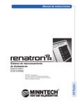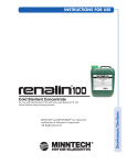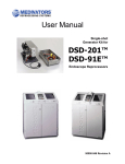
1
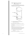
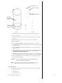
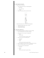
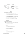
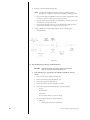
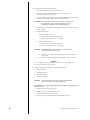
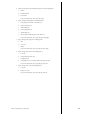
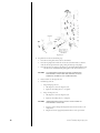
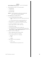
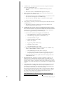
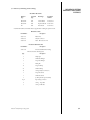
SERVICE MANUAL
®
Dialy zer Rep rocessing System
RS-8300, RS-8310, RS-8330 & RS-8335
Renatron®, Renalin®, and Actril® are registered trademarks of Minntech Corporation.
"For Institutional Use" Formula 409® is a registered trademark of the Clorox Company.
© 2007, 2005, 2004, Renal Systems, Division of Minntech Corporation.
Printed and Assembled in the United States.
All Rights Reserved.
Dear Customer:
This manual contains documents of a highly technical nature. It is intended solely for
the purpose of aiding in servicing the RS-8300, RS-8310, RS-8330 and RS-8335
Renatron® Dialyzer Reprocessing System.
Personnel attempting maintenance or repairs of this machine must be completely
familiar with troubleshooting techniques, and the contents of this manual.
Electronics training is essential for a complete understanding of the device operation.
We recommend sending the Renatron Dialyzer Reprocessing System to Minntech
Renal Systems for repair.
Minntech Renal Systems is not responsible for any damages or injuries resulting from
the operation or performance of any machine which has been repaired improperly by
non-Renal Systems personnel.
The enclosed documentation is proprietary, confidential information belonging to
Minntech Renal Systems. No other use, reproduction, or disclosure of this
information to others is authorized.
We hope the enclosed information is helpful to you. Please feel free to contact our
Technical Services Department or your Minntech Renal Systems Distributor with any
technical questions you may have.
We look forward to continuing to be of service to you.
Sincerely,
Mike Neary
Technical Services Manager
Renatron® II Dialyzer Reprocessing System
40
Renatron® II Dialyzer Reprocessing System
1.0 Introduction . . . . . . . . . . . . . . . . . . . . . . . . . . . . . . . . . . . . . . . . . . . . . . . . . . . . . . . . . . .2
TABLE OF CONTENTS
1.0 Introduction . . . . . . . . . . . . . . . . . . . . . . . . . . . . . . . . . . . . . . . . . . . . . . . . . . . . . . . . . .2
1.1 Applicable Support Documents . . . . . . . . . . . . . . . . . . . . . . . . . . . . . . . . . . . . . . . . . . . .2
1.2 Terminology . . . . . . . . . . . . . . . . . . . . . . . . . . . . . . . . . . . . . . . . . . . . . . . . . . . . . . . . . .2
2.0 Renatron System Performance Inspection Procedures . . . . . . . . . . . . . . . . . . . . . . . . . . . . .3
Renatron Di a l y zer Re p rocessing System Pe rformance Inspection Schedule . . . . . . . . . . . . . . . . .3
2.0 Calibration Verification . . . . . . . . . . . . . . . . . . . . . . . . . . . . . . . . . . . . . . . . . . . . . . . . . . . . . .3
2.1 Exterior Inspection . . . . . . . . . . . . . . . . . . . . . . . . . . . . . . . . . . . . . . . . . . . . . . . . . . . . . . . . .7
2.2 Formula 409 Se rvice Cleaning Procedure . . . . . . . . . . . . . . . . . . . . . . . . . . . . . . . . . . . . . . . .8
2.3 Quick Disconnect Inspection . . . . . . . . . . . . . . . . . . . . . . . . . . . . . . . . . . . . . . . . . . . . . . . .1 0
2.4 Re p rocessing Connector Inspection . . . . . . . . . . . . . . . . . . . . . . . . . . . . . . . . . . . . . . . . . . .1 2
2.5 Uptake Tube Assembly In s p e c t i o n . . . . . . . . . . . . . . . . . . . . . . . . . . . . . . . . . . . . . . . . . . . . .1 2
2.6 Valve Assembly Inspection for Large, Small, and V15 Valves . . . . . . . . . . . . . . . . . . . . . . . .1 4
2.7 Inspect Hydraulic Compartment for Fluid Leakage . . . . . . . . . . . . . . . . . . . . . . . . . . . . . . .2 0
2.8 Jet Pump Assembly Test Procedure . . . . . . . . . . . . . . . . . . . . . . . . . . . . . . . . . . . . . . . . . . . .2 1
2.9 Re n a t ron II System Scanner Gun . . . . . . . . . . . . . . . . . . . . . . . . . . . . . . . . . . . . . . . . . . . . .2 3
2.10 Inspect Serial Number and Preclean Barcode Labels . . . . . . . . . . . . . . . . . . . . . . . . . . . . . .2 3
2.11 Inspect Front Mask for Visual Defects . . . . . . . . . . . . . . . . . . . . . . . . . . . . . . . . . . . . . . . . 23
2.12 Check Valve Water Hose Assembly Test Procedure . . . . . . . . . . . . . . . . . . . . . . . . . . . . . . .2 4
2.13 Replace Renalog Backup Disks . . . . . . . . . . . . . . . . . . . . . . . . . . . . . . . . . . . . . . . . . . . . . .2 5
3.0 Troubleshooting Chart . . . . . . . . . . . . . . . . . . . . . . . . . . . . . . . . . . . . . . . . . . . . . . . . . . . . . .26
4.0 Renatron System Theory of Operation. . . . . . . . . . . . . . . . . . . . . . . . . . . . . . . . . . . . . . . . . .27
4.0 In p u t s . . . . . . . . . . . . . . . . . . . . . . . . . . . . . . . . . . . . . . . . . . . . . . . . . . . . . . . . . . . . . . . . . . .2 7
4.1 Outputs . . . . . . . . . . . . . . . . . . . . . . . . . . . . . . . . . . . . . . . . . . . . . . . . . . . . . . . . . . . . . . . . .2 9
5.0 Renatron System Drawings and Pa rts Listings . . . . . . . . . . . . . . . . . . . . . . . . . . . . . . . . . . . .31
6.0 Hydraulic Tank/Manifold Schematic . . . . . . . . . . . . . . . . . . . . . . . . . . . . . . . . . . . . . . . . . . .39
7.0 Long-term Storage When Not in Use . . . . . . . . . . . . . . . . . . . . . . . . . . . . . . . . . . . . . . . . . . .39
Renatron® II Dialyzer Reprocessing System
1
INTRODUCTION
1.0 Introduction
This service manual provides service and performance inspection information for the RS-8300
Re n a t ron System, RS-8330 and RS-8335 Re n a t ron II Systems.
1.1 Applicable Su p p o rt Documents
The documents listed below are available through Renal Systems Technical Se rvices Department.
A.
Renatron Instruction Manual(s)
1.
Re n a t ron In s t ruction Manual, P/N: 50104-000
2.
Re n a t ron 100 In s t ruction Manual, P/N: 50090-687
3.
Re n a t ron II In s t ruction Manual, P/N: 50097-000
4.
Re n a t ron II 100 In s t ruction Manual, P/N: 50090-680
B.
Renalog III In s t ruction for Use Manual, P/N: 50103-000
C.
Renalog RM In s t ruction Manual, P/N: 50090-859
Prior to attempting the servicing of the Re n a t ron Dialyzer Re p rocessing System, all of the above
applicable documents should be read and understood thoroughly. A thorough understanding of this
information will allow proper maintenance of the Re n a t ron Dialyzer Re p rocessing System.
D.
Additional manuals available from Minntech Renal Systems.
1.
Di a l y zer Reprocessing Guidelines - this manual is used to help in assessment of procedural
problems (non-machine related problems).
2.
Renalin In s t ructions for Use and Technical Notes - This manual outlines pro c e d u res for the
use of the Renalin Concentrate and the basic laboratory testing performed.
3.
Re n a t ron Operation Format and Program Step Outline - This manual will aid you in
understanding how the Renatron Di a l y zer Reprocessing System operates.
1.2 Terminology: For the purpose of clarity, the following terminology will be used throughout this
manual.
A.
2
“Water”or “AAMI quality water” is the water that meets or exceeds the following requirements:
1.
AAMI/ANSI Standard for Hemodialysis Systems and AAMI Recommended Practice for
the Reuse of Hemodialyzers.
2.
Containing no particles larger than 1 micron.
B.
“Renalin 100 Cold Sterilant” or “Renalin 100” is a concentrated solution for use with the
Renatron II 100 Series System. It is supplied as 3 liters of Renalin Cold Sterilant in a 1 gallon
container for use by the Renatron II 100 Series machine and for use in making a 1% Renalin
mixture.
C.
“Renalin Cold Sterilant” or “Renalin” is the concentrated solution that will be diluted by the
operator for use with the Re n a t ron II System. It is supplied as 2 liters of Renalin Cold Sterilant
in a 2.5 gallon container (9463 ml) for use by the Re n a t ron II machine or in 1 quart bottles for
use in making a 1% Renalin mixture .
D.
“Renalin Cold Sterilant solution” is a 21% solution (by volume) resulting from the operator’s
addition of AAMI quality water to Renalin Cold Sterilant and thoroughly mixing if following
the Renalin Cold Sterilant In s t ruction for Use.
E.
“Pro p o rtioned Renalin solution” is the final diluted solution, which has been further
pro p o rtioned by the Renatron II or Re n a t ron II 100 machine. This is the solution actually used
for cleaning and sterilizing the dialyzer and the Re n a t ron machine.
F.
“1% Renalin solution” - 1 part Renalin Cold Sterilant to 99 part AAMI quality water.
G.
The terms “equipment”, “machine”, “device”, “station”, or “Re n a t ron II” are synonymous with
Renatron II Di a l y zer Reprocessing Unit of the overall Renatron II System and may be used
interchangeably throughout this manual.
H.
The term “Formula 409” is “For Institutional Use” Formula 409 which is a re g i s t e red trademark
of the Clorox Company.
Renatron® II Dialyzer Reprocessing System
The pro c e d u re on the following pages will help evaluate and maintain the peak performance of the
Renatron Di a l y zer Re p rocessing System. If at any time during this process you have a question or
concern, please contact Minntech Renal Systems Technical Se rvice De p a rtment at 1-800-328-3324.
NOTE: All times and flow rates specified in this manual are approximate.
RENATRON DIALYZER REPROCESSING SYSTEM
PERFORMANCE INSPECTION SCHEDULE
Page #
Month intervals
6
9
Inspection Description
3
3
Calibration Verification
Pe rformed daily by the operator.
7
Re n a t ron Exterior Inspection
Pe rformed daily by the operator.
8
Perform 409 cleaning pro c e d u re
Pe rform this pro c e d u re eve ry 2
weeks or as needed.
10
Inspect all external Quick Disconnects for defects
and/or worn O-rings
X
X
X
X
12
Inspect Re p rocessing Connections
X
X
X
X
12
Inspect Renalin 21% and 100 Uptake Tube Assembly
14
Inspect Valve Assembly (Large, Small and V15)
X
20
Inspect Hydraulic Compartment for any signs of fluid leakage
X
21
Test Jet Pump Assembly
X
23
Inspect Re n a t ron II Scanner Gun
X
X
X
X
23
Inspect Barcode Labels for any visual defects
X
X
X
X
23
Inspect the Front Mask for any visual defects
24
Test Check Valve Water Hose Assembly
X
25
Replace Renalog Backup Disks
X
2.0
12
X
X
X
X
Calibration Verification
A.
Calibration Verification for Control Board with Potentiometers P1, P2, and P3.
1.
RENATRON SYSTEM
PERFORMANCE
INSPECTION
PROCEDURES
CALIBRATION
VERIFICATION
Each day before reprocessing dialyzers, install the Calibrated Volume Cell between arterial
and venous lines. Before checking calibration, make sure the machine is level. If the machine
is not level, retest the measurement of Volume Cell after leveling the machine. If the
displayed Renatron volume va l ve is not within ± 3 ML of the Calibrated Volume Cell,
proceed to step B.
NOTE: If the Renatron System continues to fail the calibration verification day
after day, contact Minntech Renal Systems Technical Se rvice
De p a rtment for assistance.
B.
Re n a t ron Calibration
NOTE: Before removing the top cove r, MAKE ABSOLUTELY CERTAIN
there are no loose water connections or potential for fluid leakage. ANY
FLUID DAMAGE to internal electronics is NOT COVERED by
machine warranty.
1.
In s e rt Calibrated Volume Cell between arterial and venous lines.
2.
Remove the two screws from each side of the cover and lift off the cover. Place the cover
where it will not be damaged.
3.
Press “ON” switch (“SEL” and “_ _” will be displayed).
4.
Press the “MUTE” and “RESET” switches together until the program “(00)” is displaced.
5.
Press the “HOLD TO SET” switch while adjusting the “SET” knob to display “255” in the
“VOLUME” window.
6.
Press the “START PROCESS” switch. A light will appear in corner of the “START
PROCESS” switch.
Renatron® II Dialyzer Reprocessing System
3
7.
Immediately at the end of “Program Step 05”, press the “OFF” switch.
CAUTION:
8.
SHOCK HAZARD. WHEN ADJUSTING TRIM
CONTROLS, BE CAREFUL NOT TO TOUCH
ELECTRONIC CONNECTIONS.
On the hydraulic side, view the lower tank scribe line (zero line located about 1/8” above
bottom gray gasket Fi g u re 2.0.1). Water level should be even with the lower tank scribe line.
If it is, proceed to step 9 in this procedure. If not, adjust P1 (Figure 2.0.2) and repeat steps
3-8 until water level is even with the lower tank scribe line.
Upper Tank scribe line
(507 Mark)
Lower Tank scribe line
(zero line)
Fi g u re 2.01.
NOTE: Adjust P1 (Figure 2.0.2) clockwise to raise level in tank (counterclockwise to lower level) for ze ro line adjustment. Adjust one turn to
change the level approximately 1/8”.
9.
Press “ON” switch (“SEL” and “_ _” will be displayed).
10. Press the “MUTE” and “RESET” switches together until program “(00)” is displayed.
11. Press the “HOLD TO SET” switch while adjusting the “SET” knob to display “255” in the
“VOLUME” window.
12. Press the “START PROCESS” switch. A light will appear in the corner of the “START
PROCESS” switch.
13. Immediately, at the end of “Program Step 1 2”, press the “OFF” switch.
14. On the hydraulic side, view the upper tank scribe line (507 mark located approximately in
the middle of the tank FIg u re 2.0.1). Water level should be even with the upper tank scribe
line (±1/4”). If it is , proceed to Step 1 5 in this procedure. If not, adjust P2 (Figure 2.0.2)
and repeat Steps 9-14 until water level is even with the upper tank scribe line.
NOTE: Adjust P2 (Figure 2.0.2) counter-clockwise to raise level in tank
(Clockwise to lower level). Adjust one turn to change the level
a p p roximately 1/8”.
15. Press “ON” switch (“SEL” and “_ _” will be displayed).
16. Press “MUTE” and “RESET” switches together until program “(00)” is displaye d .
4
Renatron® II Dialyzer Reprocessing System
17. Press the “HOLD TO SET” switch while adjusting the “SET” knob to display “255” in the
“VOLUME” window.
18. Press the “START PROCESS” switch. A light will appear in the corner of the “START
PROCESS” switch.
19. Allow the Renatron Station to continue operating until the “VOLUME FAIL” alarm has
occurred in “Program Step 3 5”. Push the “MUTE” switch to silence audio alarm. TAKE
CARE NOT TO PRESS THE “RESET” SWITCH.
20. The displayed Renatron volume value must be within ± 3mL of the Calibrated Volume Cell.
If the Re n a t ron System volume is not within ± 3 mL, adjust P3. Turn P3 clockwise to
decrease displayed volume value. Turn P3 counter-clockwise to increase displayed
volume value.
EXAMPLE 1
Volume Cell value equals 70 (etched value). Volume displayed by machine equals 66.
Difference in milliliters equals 4 mL. Adjust P3 (Figure 2.0.2) 1 turn counter-clockwise
per mL difference in volume value to eliminate the volume erro r. Therefore, a 4 mL
difference will require 4 turns counter-clockwise.
EXAMPLE 2
Volume Cell value equals 70 (etched value). Volume displayed by machine equals 74.
Difference in milliliters equals 4 mL. Adjust P3 (Fi g u re 2.0.2) 1 turn clockwise per mL
difference in volume value to eliminate the volume erro r. Therefore, a 4 mL difference
will require 4 turns clockwise.
NOTE: If P3 is adjusted while the volume is being displayed, no change will be
shown in the display. The change in volume value will be evident only
after pressing the “RESET”, “HOLD TO SET”, and “START
PROCESS” switches to retest the volume.
21. Repeat Steps 15-20 until displayed Re n a t ron System volume is within ± 3 mL of the
Calibrate Volume Cell.
22. Replace the Re n a t ron System cove r, securing it with the two screws on each side.
NOTE: If the Renatron Station will not calibrate, please call Minntech Renal
Systems Technical Se rvice De p a rtment at 1-800-328-3324 for assistance.
Tank Zero Level
Potentiometer - P1
Tank Gain Level
Potentiometer - P2
“VOLUME” Meter
Level
Potentiometer - P3
Figure 2.0.2
Renatron® II Dialyzer Reprocessing System
5
C.
Renatron II Station Calibration Procedure for Single Bo a rd Controller.
NOTE: You should complete steps 4-6 within 60 seconds. If you do not complete
the sequences within 60 seconds, the Re n a t ron Station will return to an idle
mode. You can terminate calibration and return to the idle mode by pressing
“RESET” at anytime, except during the calibration cell measurement test. If
the process is terminated, the new calibration parameters are voided and the
previous calibration parameters are valid. You will need to start the
calibration procedure from the beginning and complete it for the new
calibration parameters to become valid.
WARNING: SHOCK HAZARD - WHEN PRESSING SWITCHES BE
CAREFUL NOT TO TOUCH ELECTRONIC CONNECTIONS.
NOTE: Before re m oving the top cover, MAKE ABSOLUTELY CERTAIN there are
no loose water connections or potential for fluid leakage. ANY FLUID
DAMAGE to internal electronics is NOT COVERED by machine warranty.
1.
In s e rt Calibrated Volume Cell between arterial and venous lines.
2.
Remove the two screws from each side of the cover and lift off the cover. Place the cover
where it will not be damaged.
3.
Press “ON” switch (“SEL” and “_ _” will be displayed).
4.
Press and hold the “SETUP” switch (S3 on the microprocessor board) for 4 seconds until yo u
hear the second “chirp”. The “P ROGRAM STEP” will display “c1” and “CAL” will be
displayed on the Volume Display (Figure 2.0.4).
5.
Pressing and holding the “INCR” switch (S2) or the “DECR” switch (S1) adjust the liquid
level in the tank to the “0” reference line (lower tank scribe line).
6.
Press and release the “SETUP” switch (S3) (Figure 2.0.4). You will hear one chirp. The
“PROGRAM STEP” will display “cA”.
7.
Using the “INCR” switch (S2) and the “DECR” switch (S1) adjust the liquid level in the
tank to the 507 reference line (upper tank scribeline) (Figure 2.0.3).
8.
Press and release the “SETUP” switch (S3). You will hear on chirp. The Renatron Station will
then begin to run through Steps 1 - 1 5. This will fill and test the calibration cell. When the
Renatron Station has completed the cycle, “cb” will be displayed in the “PROGRAM STEP”
and the calibration cell volume will be displayed in the “VOLUME” display.
9.
Using the “INCR” switch (S2) and the “DECR” switch (S1) adjust the 3-digit “VOLUME”
display to match the reference volume of the calibration cell.
10. Press and release the “SETUP” switch (S3). The Renatron Station will exit the calibration mode.
NOTE: The new calibration values are not saved until you complete Step 1 0 and
exit the calibration mode.
11. Press the “HOLD-TO-SET” switch and use the silver “SET KNOB” to adjust the volume
display to 255, then press the “MUTE” and “RESET” switches together until program “
(00)” is displaye d .
12. Press the “START PROCESS” switch. A light will appear in the corner of the
“START PROCESS” switch.
13. Allow the Re n a t ron II Station to continue operating until it enters “Program Step 8”.
14. Press the “OFF” switch.
15. Verify that the liquid level in the tank is at the ze ro reference line (lower tank scribe line).
16. If the liquid level is above or below the ze ro re f e rence line repeat Steps 3 - 1 5.
17. Press the “ON” switch.
18. Press the “HOLD-TO-SET” switch and use the silver “SET KNOB” to adjust the volume
display to 255, then press the “MUTE” and “RESET” switches together until program “
(00)” is displaye d .
19. Press the “START PROCESS” switch. A light will appear in the corner of the “START
PROCESS” switch.
6
Renatron® II Dialyzer Reprocessing System
Increase Switch - S2
Decrease Switch - S1
Setup Switch - S3
Upper tank
scribe line
(507 Mark)
Lower tank
scribe line
(Zero line)
Figure 2.0.3
Figure 2.0.4
20. Allow the Renatron II Station to continue operating until it enters “Program Step 1 4”.
21. Press the “OFF” switch.
22. Verify that the liquid level in the tank is at the 507 reference line (upper tank scribe line)
Figure 2.0.3.
23. If the liquid level is above ro below the 507 reference line repeat Steps 3-22.
24. Press the “ON” switch.
25. Press the “MUTE” and “RESET” switches together until program “(00)” is displaye d .
26. Press the “HOLD TO SET” switch while adjusting the “SET” knob to display “255” in the
“VOLUME” window.
27. Press the “START PROCESS” switch. A light will appear in the corner of the “START
PROCESS” switch.
28. Allow the Renatron II Station to continue operating until the “VOLUME FAIL” alarm has
occurred in “Program Step 3 5”. Push the “MUTE” switch to silence the audio alarm.
DO NOT PRESS THE “RESET” SWITCH.
29. The displayed Renatron II Station volume value must be within ± 3 mL of the Calibrated
Volume Cell. If the Renatron II volume is not within ± 3 mL, press reset and repeat Steps 4-28.
30. Replace the Re n a t ron II Station cover, securing it with the two screws on each side. The
screw should be thumb tightened.
CAUTION:
NOTE:
THE COVER SHOULD ALWAYS BE ON THE RENATRON II
STATION FOR NORMAL OPERATION.
If Re n a t ron II Station will not calibrate, please call Minntech Renal Systems
Technical Se rvices De p a rtment at 1-800-328-3324 for assistance.
2.1 Exterior Inspection
A.
The Re n a t ron System should be inspected periodically for any defects such as the following list:
1.
Bent or broken switches
2.
Cracks in the cover
3.
Corroded metal part s
Renatron® II Dialyzer Reprocessing System
7
B.
4.
Loose or missing hardware
5.
Cut or frayed hoses or electrical cord s .
6.
Exc e s s i ve protein deposits in the tubing. If necessary, see the Formula 409 Se rvice
Cleaning Procedure.
CAUTION:
USE OF A RENATRON II DIALYZER REPROCESSING
STATION ON WHICH ONE OR MORE OF THE ABOVE
CONDITIONS EXIST SHOULD BE DISCONTINUED
UNTIL THE DEFECT IS CORRECTED AND THE
SYSTEM OPERATION IS VERIFIED.
CAUTION:
CARE SHOULD BE TAKEN TO AVOID EXCESS
MOISTURE WHICH COULD FLOW INTO THE
RENATRON II DIALYZER REPROCESSING STATION
CASE ASSEMBLY. BLOOD MAY BE REMOVED FROM
THE EXTERIOR OF THE RENATRON II WITH FRESH
1% RENALIN SOLUTION OR FULL STRENGTH
ACTRIL® SOLUTION. DO NOT USE ANY OTHER
CLEANERS, AS THEY MAY BE INCOMPATIBLE WITH
THE MATERIALS IN THE MACHINE.
Cleaning: The exterior of the Renatron II Station should be cleaned as often as operating
conditions re q u i re.
CAUTION:
ANY LIQUID SPILLED ON THE MACHINES EXTERNAL
SURFACES SHOULD BE W I PED OFF IMMEDIATELY TO
REDUCE THE POSSIBILITY OF MOISTURE ENTERING
THE MAIN CASE ASSEMBLY. IF SUCH A CONDITION
WERE TO EXIST, IT COULD CREATE AN ELECTRICAL
CONDUCTIVE PATH WHICH COULD RESULT IN
INSTRUMENT FAILURE. NO LIQUID(S) SHOULD BE
USED NEAR THE COMPUTER KEYBOARD AND
MONITOR.
CAUTION:
DO NOT USE CHEMICAL CLEANING AG E N TS THAT
COULD DAMAGE THE PLASTICS USED IN THIS
MACHINE. AVOID CHEMICALS WHICH CONTAIN
ALCOHOL, BENZENE, TOLUENE, XYLENE, ACETONE
OR OTHER AROMATIC OR KETONE SOLVENTS. DO
NOT USE BLEACH.
2.2 Formula 409 Se rvice Cleaning Procedure
A.
The internal fluid pathways must be cleaned periodically (typically eve ry 2 weeks) as
outlined below :
Re n a t ron II machines experience deposits which gradually build up inside the blood lines with
continued machine use. The amount of build up is pro p o rtional to the extent of machine use,
the number of dialyzers re p rocessed, and such factors as heparin regime and rinse back method.
This build up is a waxy, denatured substance with a slight ye l l ow tint. If the build is allowed to
continue, the machine may give erroneous blood volume readings (low) and may stop operating
altogether. Before this substance becomes visually evident in the blood lines, the procedure
outlined below should be performed to re m ove the deposits.
CAUTION:
8
THIS PROCEDURE CALLS FOR USE OF INSTITUTIONAL
FORMULA 409. THIS LIQUID CHEMICAL IS AN EYE
IRRITANT. AVOID CONTACT WITH EYES OR SKIN.
REFER TO LABEL INSTRUCTIONS CAUTIONS AND
REMEDY. DO NOT USE SUBSTITUTE CHEMICAL
SOLUTIONS IN THIS PROCEDURE.
Renatron® II Dialyzer Reprocessing System
Institutional Formula 409 will not react with trace levels of Renalin Cold Sterilant
Concentrate/Renalin 100. To ensure Formula 409 contact with Renalin concentrate is minimized
and to ensure Formula 409 is rinsed completely from the Re n a t ron station, this procedure
should be performed in the order as listed.
1.
Remove uptake tube from Renalin container and make sure excess Renalin concentrate
drains back into the container. Cover the open Renalin container.
2.
Place uptake tube into a container of purified water (1 gallon or more).
3.
Press the “ON” switch, and select program “00”. Connect the external hoses in the
sanitize configuration.
4.
Press the “START SANITIZE” switch. Allow machine to operate to completion of
“Program Step 7 5” and press “OFF” switch. (No problems will occur if machine
operates past Step 7 5, before turning off ).
5.
Press “ON” switch and repeat pro c e d u re Steps 3 and 4 above. This action clears the Renalin
concentrate from uptake hose and replaces it with pure water.
6.
Remove the uptake tube from pure water and allow excess water to drain out of
uptake tube.
7.
Place the uptake tube into the container of Formula 409. The 64 U.S. fl. oz. (1.89 liter) size
will work conveniently.
8.
Press the “ON” switch and repeat the procedures in Steps 3 and 4 above. This action clears
the water from the uptake hose and replaces it with Formula 409.
9.
Press “ON”, select program “(00)”, and press the “START SANITIZE” switch. Allow the
machine to continue operating to “SANITIZE COMPLETE” in “Program Step 8 3”.
10. Press the “OFF” switch and turn off the water supply to the machine. Leave the machine
overnight.
NOTE: Minimum contact time is 8 hours. Optimal contact time is several days
(over the weekend). The maximum contact time is 7 days.
11. Remove the uptake tube from the container of Formula 409 and make sure the excess 409
drains from the tube back into the container. Place the uptake tube in a container of pure
water (1 gallon or more). Turn the water supply on.
12. Press “ON”, select program “(00)”, and press the “START SANITIZE” switch. Allow the
machine to operate to completion of “Program Step 7 5”, and press the “OFF” switch.
(No problems will occur if the machine operates past Step 75 before turning off.) This
action clears the Formula 409 from the uptake hose and replaces it with water.
13. Press “ON”, select program “(00)”, and press the “START SANITIZE” switch. Allow the
machine to operate to “Program Step 8 3” and when machine completes Step 8 3, press
“START PROCESS” switch. The machine will then enter Step 8 4, and after a ten minute
hold in Step 8 4, will proceed with flushing and draining. The flushing and draining will
continue until the machine enters “Program Step 9 7” and the “SANITIZE COMPLETE”
message reappears.
14. Press the “OFF” switch when the “SANITIZE COMPLETE” message appears in
“Program Step 9 7”.
15. Remove the uptake tube from the container of pure water and allow the excess water to
drain from the uptake tube.
16. Place the uptake tube in a container of properly diluted, non-expired Renalin Solution or
non-expired Renalin 100 container.
17. Press “ON”, select program “(00)”, and press the “START SANITIZE” switch. Allow the
machine to operate to completion of “Program Step 7 5” and press the “OFF” switch.
This action clears the water from the uptake hose and replaces it with Renalin Cold
Sterilant solution.
18. Press “ON”, select program “(00)”, and press the “START SANITIZE” switch. Allow
machine to operate to “Program Step 8 3”. When the machine completes Step 8 3, press
“START PROCESS” switch. The machine will then enter Step 84 and after a ten minute
hold time will proceed to “Program Step 9 7”. The “SANITIZE COMPLETE”
message will reappear.
Renatron® II Dialyzer Reprocessing System
9
19. Your Re n a t ron station is now ready for normal use.
NOTE: Formula 409 is a registered trademark of the Clorox Co., Oakland,
CA. It is available as Minntech Renal Systems P/N: 93250-092.
Minntech Renal Systems’ International Distributors should contact
Minntech Renal Systems to obtain this product if not available locally.
2.3 Quick Disconnect Inspection - Hansen Connectors
A.
B.
Quick Disconnect Inspection-Hansen Connectors - 47702-000 and 47875-000:
1.
Inspect the inside and outside of the quick disconnects for any corrosion/deterioration.
2.
Inspect ball bearings inside of quick disconnects for any flatness or corrosion/deterioration.
3.
Inspect outside collar for smooth sliding action.
4.
Inspect for missing ball bearings.
5.
Inspect Quick Disconnect o-ring for the following defects:
a.
Worn/Disfigured
b.
Chipped/Pitted
c.
Deteriorating
If replacement is needed, use the following steps:
1.
Replacement for Female Socket P/N: 47702-000
Fi g u re 2.3.1
10
a.
Remove Female Socket from dialyzer holder using a 1-1/16” open end wrench.
b.
Remove old silicone from dialyzer holder.
c.
Place a small amount of silicone RTV, P/N: 17512-000, on the threads of the new
Female Socket, P/N: 47702-000.
d.
Tighten the Female Socket with the male to male connector installed. With interlock
rod pushed in, leave a gap of 1/8” between the male to male connector and the rod.
Renatron® II Dialyzer Reprocessing System
2.
Replacement for the Dialysate Connector P/N: 47875-000
Fi g u re 2.3.2
C.
D.
a.
Cut the tie wrap off of the tubing.
b.
Remove Dialysate Connector from tubing.
c.
Push new Dialysate Connector into tubing.
d.
Secure with a new tie wrap around the tubing.
A defect in the Hansen Quick Disconnect Connector can cause the following symptoms:
1.
Fluid leakage at Quick Disconnect
2.
Pressure Fa i l u re Alarms
3.
Tank Volume Alarms
Quick Disconnect Inspection - Female Swivel Connector, P/N: 47502-022.
1.
Verify the Re p rocessing Connector/ISO assembly “snaps” into the Female Swivel Connector
and is firmly held in place.
2.
Run the Re n a t ron System through Step 1 4 in the “00” mode with the Renatron Station in
sanitize configuration. Check for leaks at the female swivel connector.
3.
Replace the Female Sw i vel Connector if leaks are detected.
Fi g u re 2.3.3
E.
A defective Female Sw i vel Connector can cause:
1.
Leakage during Step 1 4.
2.
Tank volumes in Step 4.
3.
Low volumes in Step 3 5.
Renatron® II Dialyzer Reprocessing System
11
2.4 Reprocessing Connector Inspection
A.
Re p rocessing Connector Inspection
1.
2.
Inspect the Reprocessing Connector for the following defects:
a.
Worn O-ring
b.
Bent connector body
c.
Cracking
Replace the re p rocessing connector if any defects are noted.
Figure. 2.4.1
B.
A defective Re p rocessing Connector can cause the following symptoms:
1.
Fluid leakage at the re p rocessing connector connections
2.
Tank Volume Alarm in Step 4.
3.
Volume Fail Alarm in Step 3 5.
2.5 Uptake Tube Assembly Inspection
A.
Use the following to properly inspect the Renalin 21% uptake tube assembly:
1.
Inspect the ball check valve to insure the ball is moving freely.
2.
Inspect the male connector O-ring for the following defects:
a.
Flatness
b.
Brittleness/Cracks
If any of the above defects exist, replace the O-ring.
3.
Inspect the male connector for the following defects:
a.
Discoloration
b.
Brittleness
c.
Cracks
If any of the above defects exits, replace the O-ring.
4.
Inspect the modified cap to insure the vent hole is not plugged, replace if necessary.
5.
Inspect the tube fitting assembly for any cracks, replace if necessary.
6.
Inspect the suction tube for the following defects:
a.
Discoloration
b.
Brittleness
c.
Cracks
If any of the above defects exist, replace the O-ring.
12
Renatron® II Dialyzer Reprocessing System
Tube Fitting Assy.
(Inside the circle)
Figure 2.5.1
B.
C.
If replacement is needed, use the following steps:
1.
Re m ove the male connector from the ball check valve.
2.
Re m ove the tube fitting assembly and modified cap from ball check va l ve.
3.
Place a small amount of silicone RTV, P/N: 17512-000 on the male threads of the new
male connector, P/N: 47502-003.
4.
Tighten the male connector into the top of the new ball check valve, P/N: 41005-001.
5.
Place a small amount of silicone RTV, P/N:17512-000 on the male threads of the new
tube fitting assembly, P/N: 47885-000.
6.
Make sure modified cap is placed over the top of the tube fitting assembly.
7.
Place the new suction tube, P/N: 47606-001 inside of the tube fitting assembly.
8.
Tighten the tube fitting assembly into the bottom of the ball check va l ve.
A defect in the Renalin Uptake Tube Assembly can cause the following symptom:
1.
D.
Add Chemical Alarm
Renalin 100 Uptake Tube Assembly Inspection
NOTE: Use the following steps too properly inspect the Renalin 100 uptake tube assembly.
1.
Inspect the barbed adapter for the following defects:
a.
Discoloration
b.
Brittleness
c.
Cr a c k s
If any of the above defects exist, replace the barbed adapter.
2.
Inspect the modified cap to insure the vent hole is not plugged, replace if necessary.
3.
Inspect the female tube fitting for any cracks, replace if necessary.
4.
Inspect the suction tube for the following defects:
a.
Discoloration
b.
Brittleness
c.
Cr a c k s
If any of the above defects exist, replace the suction tube
5.
Replace Renalin 100 Check va l ve annually.
Renatron® II Dialyzer Reprocessing System
13
E.
Renalin 100 Check Valve Replacement Procedure
NOTE: The uptake tube assembly and check va l ve contain 100% Renalin concentrate.
Personal pro t e c t i ve equipment is re q u i red when performing the following procedure.
F.
1.
Inspect the entire length of red Renalin hose. If the hose is brittle or bleached white, it may
be necessary to replace the entire length of hose (P/N: 47509-249).
2.
Disconnect both ends of the check valve from the Renalin hose. It may be necessary to cut
the Renalin hose to re m ove the check valve.
3.
In s e rt new check va l ve (P/N: 41600-113) into the red Renalin hose. Make sure that the
c u rved side of the check va l ve is in the up position (see Fi g u re 2.5.2)
A defect in the Renalin 100 Uptake Tube Assembly can cause the following problem:
1.
Add chemical alarm
(47509-320)
Fi g u re 2.5.2
2.6 Valve Assembly Inspection for Large, Small, and V15 Valves
CAUTION:
A.
TURN THE POWER OFF, UNPLUG THE UNIT FROM THE
WALL OUTLET, AND TURN THE WATER OFF.
Use the following steps to properly inspect the small valve assemblies V2, V10, V12,
and V13:
1.
Remove the nut from the small va l ve coil using pliers.
2.
Remove the small valve coil from the small valve stem.
3.
Remove the washer from the small valve stem.
4.
Remove the small valve stem with a flat bladed screw driver.
5.
Remove the O-ring form the manifold and inspect it for following defects:
a.
Flatness
b.
Brittleness/Cracks
c.
Deterioration
If any of the above defects exist, replace the O-ring.
6.
Inspect the small valve plungers for the following defects:
a.
Rubber seat
1.
14
C i rcle impression off center on the rubber seat
Renatron® II Dialyzer Reprocessing System
b.
2.
Chips in the rubber seat
3.
Un l e vel rubber seat
4.
Deteriorating rubber seat
5.
Swollen rubber seat
6.
An incomplete circular impression in the rubber seat
Spring
1.
Bent
2.
Corroded
3.
Broken
If any of the above defects exist, replace the small valve plunger.
7.
Inspect the small valve stems for the following defects:
a.
Corrosion
b.
Crimp marks in the valve stem
c.
Damaged thread
d.
Valve plunger does not move freely inside of the small valve stem.
If any of the above defects exist, replace the small valve stem.
8.
Inspect the small valve coil for the following defects:
a.
Corrosion
b.
Frayed or cut wires
If any of the above defects exist, replace the small valve coil.
Fi g u re 2.6.1
Renatron® II Dialyzer Reprocessing System
15
B.
If replacement is needed, use the following steps:
1.
In s e rt the O-ring, P/N: 41014-015, into the manifold.
2.
In s e rt the small va l ve plunger, P/N: 41014-004, into the small va l ve stem,
P/N: 41014-003. Check for spring action.
3.
In s e rt the small va l ve stem and plunger into the manifold. Hand-tighten the va l ve stem into
the manifold and then gently tighten it with a flat-bladed screwdriver.
CAUTION:
USE CARE WHILE INSTALLING THE VALVE STEM BECAUSE
THE MANIFOLD VALVE PORT IS SENSITIVE TO CROSSTHREADING, STRIPPING AND OVERTIGHTENING.
4.
Place the washer onto the small va l ve stem. The gro ove in the washer should be facing away
from the manifold.
5.
Install the small valve coil.
a.
b.
Using existing small valve coil
1.
Slide small va l ve coil onto the small valve stem.
2.
Replace the nut making sure not to over-tighten.
Using a new small valve coil
1.
Slide small va l ve coil onto the small valve stem.
2.
Replace the nut making sure not to over-tighten.
CAUTION:
OVERTIGHTENING THE NUT COULD CAUSE DAMAGE
TO THE MANIFOLD VALVE PORT.
3.
Route the coil wires through the wiring harness and secure the coil wires to the
wiring harness.
4.
Plug the wires into the appropriately labeled connectors on the power board.
EXAMPLE 1
If you are replacing the coil on valve number 2, the coil wires would be plugged onto
the connectors labeled V2 on the power board.
C.
A defect in the small va l ve assembly can cause the following symptoms:
1.
Tank Volume Alarm
2.
Add Chemical Alarm
3.
Volume Failure Alarm
4.
Pressure Failure Alarm
CAUTION:
D.
16
TURN THE POWER OFF, UNPLUG THE UNIT FROM THE
WALL OUTLET, AND TURN THE WATER OFF.
Use the following steps to properly inspect the large valve assemblies V1, V3, V4, V5, V6, V7,
V8, V9, and V11:
1.
Remove the nut from the coil using a pliers.
2.
Pull the large valve coil off of the large va l ve stem.
3.
Remove the washer from the large valve stem.
4.
Remove the large valve stem with the valve removal tool, P/N: 78207-000.
Renatron® II Dialyzer Reprocessing System
5.
Remove the O-ring from the manifold and inspect it for the following defects:
a.
Flatness
b.
Brittleness/Cracks
c.
Deterioration
If any of the above defects exist, replace the O-ring.
6.
Inspect the large valve plungers for the following defects:
a.
Circle impression off center on the rubber seat
b.
Chips in the rubber seat
c.
Unlevel rubber seat
d.
Deteriorating rubber seat
e.
Swollen rubber seat
f.
An incomplete circular impression in the rubber seat
If any of the above defects exist, replace the large valve plunger.
7.
Inspect the large valve spring for the following defects:
a.
Bent
b.
Corrosion
c.
Broken
If any of the above defects exist, replace the large valve spring.
8.
Inspect the large valve stems for the following defects:
a.
Corrosion
b.
Crimp marks in the valve stem
c.
Damaged threads
d.
Valve plunger does not move freely inside of the large va l ve stem.
If any of the above defects exist, replace the large valve stem.
9.
Inspect the large valve coil for the following defects:
a.
Corrosion
b.
Frayed or cut wires
If any of the above defects exist, replace the large valve coil.
Renatron® II Dialyzer Reprocessing System
17
Fi g u re 2.6.2
E.
If replacement is needed, use the following steps:
1.
In s e rt the new O-ring, P/N: 41015-015, into the manifold.
2.
In s e rt the new plunger, P/N: 41015-004, into the va l ve stem, P/N: 41015-003. Check to
make sure that the tapered end of the spring is facing the rubber tip of the plunger.
3.
In s e rt the large va l ve stem and large valve plunger into the manifold. Hand tighten the large
valve stem into the manifold and then gently tighten it with the va l ve re m oval tool.
CAUTION:
4.
Place the washer onto the large va l ve stem.
5.
Install the large valve coil.
a.
b.
Using existing large valve coil.
1.
Slide large va l ve coil onto the large va l ve stem.
2.
Replace the nut making sure not to over-tighten.
Using a new large va l ve coil.
1.
Slide large va l ve coil onto the large va l ve stem.
2.
Replace the nut making sure not to overtighten.
CAUTION:
18
USE CARE WHILE INSTALLING THE VALVE STEM BECAUSE
THE MANIFOLD VALVE PORTS AREA SENSITIVE TO CROSSTHREADING, STRIPPING, AND OVERTIGHTENING.
OVERTIGHTENING THE NUT COULD CAUSE DAMAGE TO
THE MANIFOLD VALVE PORT.
3.
Route the coil wires through the wiring harness and secure the coil wires to the
wiring harness.
4.
Plug the wires into the appropriately labeled connectors on the power board.
Renatron® II Dialyzer Reprocessing System
EXAMPLE 1
If you are replacing the coil on the valve number 1, the coil wires would be plugged on
the connectors labeled V1 on the power board .
F.
A defect in the large va l ve assembly can cause the following symptoms:
1.
Tank Volume Alarm
2.
Add Chemical Alarm
3.
Volume Fa i l u re Alarm
4.
Pressure Fa i l u re Alarm
CAUTION:
G.
Use the following steps to properly inspect va l ve 15:
1.
H.
TURN THE POWER OFF, UNPLUG THE UNIT FROM THE
WALL OUTLET, AND TURN THE WATER OFF.
Connect the machine tubing in the sanitize configuration.
a.
Connect the dialysate inlet and outlet connectors together using the male to male
adapter.
b.
Connect the arterial and venous hoses together using the calibration cell.
2.
Run the machine in the “00” mode. Press the “START PROCESS” switch.
3.
During Step 5, remove the dialysate inlet line from the male to male connector.
4.
Feel for suction. It should pull in on the glove on your hand.
5.
Replace the dialysate inlet line onto the male to male connector.
6.
Run the machine up to Step 9.
7.
Time how long it takes the Renatron Station to complete Step 9.
8.
Step 9 should take between 10 to 12 seconds for the 21% Re n a t ron System and 4 to 8
seconds for Renalin 100 to complete. If there is strong suction in Step 5 and Step 9 is longer
than 20 seconds, replace the valve 15 diaphragm P/N: 41013-001.
If replacement is needed, use the following steps:
1.
Remove two phillips head screws from the valve 15 assembly.
2.
Remove the va l ve 15 assembly from the manifold block.
3.
Look for the following defects in the va l ve 15 diaphragm:
4.
a.
Blistering
b.
Leaking
c.
Disfigured
Inspect the va l ve 15 coil for the following defects:
a.
Corrosion
b.
Frayed or cut wires
If any of the above defects exist, replace the va l ve 15 coil.
Renatron® II Dialyzer Reprocessing System
19
Fi g u re 2.6.3
5.
Inspect the valve 15 spring for the following defects:
a.
Bent
b.
Corrosion
c.
Broken
If any of the above defects exist, replace the valve 15 assembly.
6.
In s e rt the new valve 15 diaphragm P/N: 41013-001 on the metal plunger.
7.
Place the metal plunger with diaphragm inside the coil. Make sure the spring is inside the
metal plunger.
8.
In s e rt the va l ve 15 assembly into the manifold block.
9.
a.
diaphragm goes into the manifold first.
b.
O-ring goes between the diaphragm and the valve coil.
c.
Place the metal plunger with spring inside.
d.
The valve coil goes in last.
Tighten the phillips head screws evenly, making sure not to over-tighten.
CAUTION:
I.
OVERTIGHTENING OF THE SCREW(S) COULD CAUSE
DAMAGE TO THE MANIFOLD. UNEVEN TIGHTENING
MAY CAUSE THE DIAPHRAGM AND O-RING TO BE
IMPROPERLY ALIGNED.
A defect in the va l ve 15 Assembly can cause the following symptom:
1.
Add Chemical Alarms
2.7 Inspect Hydraulic Compartment for Fluid Leakage
CAUTION:
20
POWER DOWN MACHINE AND UNPLUG FROM WALL OUTLET.
TURN OFF WATER SUPPLY VALVE.
Renatron® II Dialyzer Reprocessing System
A.
Re m ove cover and inspect the hydraulic compartment, for any sign of moisture .
B.
Some areas where leaks may occur are:
C.
D.
1.
The pressure transducer/baffle assembly
2.
The quick connect fittings on the front of the manifold
3.
Any of the tank fittings, or the tank itself
4.
Any of the va l ve guides located on the manifold
Leaks may be caused by any of the following problems:
1.
Defective valve guide
2.
Cracked/worn fitting or O-ring
3.
Defective manifold
Internal leaks may cause the following alarms:
1.
Add Chemical
2.
Tank Volume
3.
Pressure Fail
2.8 Jet Pump Assembly Test Procedure
A.
Use the following steps to properly test the jet pump assembly:
1.
B.
Place the Re n a t ron Station into the sanitize configuration using the following steps:
a.
Connect the dialysate inlet and outlet connectors together using the male to
male adapter.
b.
Connect the arterial and venous hoses together using the calibration cell.
2.
Run the machine in the “(00)” mode. Push the “START PROCESS” switch.
3.
During Step 5, remove the dialysate inlet line from the male to male connector.
4.
Feel for suction at the dialyzer holder. It should pull in on the glove on your hand.
5.
Replace the dialysate inlet line onto the male to male connector.
6.
Run the machine up to Step 9.
7.
Time how long it takes the Renatron Station to complete Step 9.
8.
Step 9 should take between 10 to 12 seconds for the 21% Re n a t ron Station and 4 to 8 seconds
for Renalin 100 to complete. If there is weak suction in Step 5 or if Step 9 is longer
than 20 seconds, replace the jet pump nozzle spacer assembly, P/N: 78397-842.
If there is strong suction in Step 5 and Step 9 is longer than 20 seconds, proceed
to the Valve 15 Inspection procedure.
If replacement is needed, use the following steps:
1.
Removal of jet pump assembly.
a.
Turn off the incoming water.
b.
Disconnect the incoming water and drain lines from the back of the machine.
c.
Remove the drain fitting (jet pump retainer) from the back of the machine.
d.
Remove the O-ring that is attached to the drain fitting.
Renatron® II Dialyzer Reprocessing System
21
Diffuser
Assembly
Nozzle Spacer
Assembly
Fi g u re 2.8.1
e.
Using the metal pin in the diffuser, pull out the diffuser shaft. This assembly has two
O-rings attached to it. You will be looking for the following defects in the O-rings
and diffuser:
1.
Flatness
2.
Swollen
3.
Discolored
4.
Brittleness/Cracks
If any of the above defects exist, replace the O-rings.
f.
Using the Jet Pump Re m oval Tool (P/N: 47048-001) insert the tool into the manifold
hooking the jet pump spacer and nozzle at the 12:00 position. Pull the assembly straight
out of the machine. Re m ove the O-ring from the end of the jet pump nozzle. If the
O-ring is not on the end of the nozzle assembly, use the Jet Pump Re m oval Tool to
re m ove the O-ring from the inside of the manifold. You will be looking for the following
defects in the jet pump spacer and nozzle:
1.
Nozzle spacer assembly can be separated into two pieces
2.
Discolored
3.
Brittleness/Cracks
If any of the above defects exist, replace the jet pump assembly.
g.
Inspect jet pump O-rings for the following defects:
1.
Flatness
2.
Swelling
3.
Discoloration
If any of the above defects exist, replace the O-rings.
NOTE:
2.
22
A small amount of Dow Corning III (17542-000) can be applied to the Jet
Pump O-rings to hold them in place while the Jet Pump is re-assembled.
Install the jet pump assembly.
a.
Install the O-ring on the back of the jet pump assembly.
b.
Connect the diffuser to the jet pump assembly by the male and female notches on
the assemblies.
Renatron® II Dialyzer Reprocessing System
C.
c.
Slide the assembly back into the manifold with the jet pump assembly going in first.
Make sure that the metal pin in the diffuser matches up with the notch in the manifold
at the 12:00 position.
d.
Attach the O-ring to the back of the drain fitting.
e.
Screw the drain fitting back into the manifold.
f.
Reattach the drain hose and the incoming water line to the machine.
A defect in the jet pump assembly could cause one or more of the following problems:
1.
Tank Volume Alarm
2.
Add Chemical Alarm
3.
Volume Fail Alarm
4.
Pressure Fail Alarm
2.9 Renatron II System Scanner Gun
A.
Cleaning the Scan Window
Scanning performance may degrade if the scan window is not clean. If the window is visibly
dirty, or if the scanner isn’t scanning well, clean the scan window with a soft cloth or facial tissue
dampened with water (or a mild detergent-water solution). If a detergent solution is used, rinse
with a clean tissue dampened with water only.
B.
Inspecting the Cords and Connectors
Inspect the interface cable and connector for wear or other signs of damage. A badly worn cable
or damaged connector may interf e re with scanner operation. Contact Minntech Renal Systems
for information about cable replacement.
C.
Examining the Scanner Housing
Routinely examine the housing for signs of damage. A damaged housing may cause the internal
components to move and may result in a malfunctioning scanner.
2.10 Inspect Serial Number and Preclean Barcode Labels
A.
B.
Inspect the labels for the following:
1.
Missing
2.
Torn
3.
Edges that are curling up
Defects may cause the following problems:
1.
Communication erro r s
2.
The scanner will not be able to complete the scan
2.11 Inspect Front Mask for Visual Defects
A.
Inspect the front mask for tears and cracks:
1.
Any tears or cracks in the switch area of the front mask will eventually cause the switches
to fail.
NOTE:
It is recommended that Re n a t ron Station be returned to Minntech Renal Systems
for repair if the switches or mask are defective.
Renatron® II Dialyzer Reprocessing System
23
2.12 Check Valve Water Hose Assembly Test Procedure
NOTE:
If you do not have a Minntech Renal Systems pressure regulator with a
pressure gauge, you must place a pressure gauge device between the
water hose assembly and the Re n a t ron water inlet fitting. Any one of the
following items would be an acceptable device to use for this test.
CAUTION:
THE RENATRON STATION MUST NOT BE OPERATED
WITHOUT THE CHECK VALVE ASSEMBLY.
Water Pressure Gauge Assembly P/N: 78207-010
Single Pressure Regulator with Gauge P/N: 78327-020
Dual Pressure Regulator with Gauge P/N: 78327-021
A.
Use the following steps to properly test the Check Valve Water Hose assembly:
1.
In s e rt Calibrated Volume Cell between arterial and venous lines.
2.
Press “ON” switch (“SEL” and “--” will be displaye d ) .
3.
Press the “MUTE” and “RESET” switches together until program “(00)” is
displayed.
4.
Press the “HOLD TO SET” switch while adjusting the “SET” knob to display
“255” in the “VOLUME” window.
5.
Press the “START PROCESS” switch. A light will appear in corner of the “START
PROCESS” switch.
6.
Ob s e rve pressure reading during Step 4. The Renatron water pressure specification
is 20-55 psig, however the optimal dynamic water pressure is 30-55 psig in Step 4.
If water pressure is a problem, check the following items:
a.
Water system output pressure to reuse ro o m .
b.
If you have a pressure regulator in-line, check the setting and adjust
if necessary.
c.
Replace Check Valve Water Hose Assembly.
7.
Turn incoming water supply off.
8.
Disconnect the water hose assembly from the incoming water supply valve.
9.
Disconnect the other end of the water hose assembly.
10. With the Check Valve flow arrow pointing upward, fill the water hose assembly
with R.O. water through the Hansen connector.
11. Place a mark on the water hose assembly to correspond to the water leve l .
12. Monitor the water level for 2 minutes. If the water level has decreased replace the
Check Valve Water Hose assembly.
13. Reinstall the Check Valve Water Hose assembly.
14. Turn on the incoming water supply va l ve.
B.
C.
24
If replacement is needed, use the following steps:
1.
Purchase Check Valve Water Hose assembly P/N: 78158-000
2.
Turn incoming water supply off.
3.
Disconnect the water hose assembly from the incoming water supply valve.
4.
Disconnect the other end of the water hose assembly.
5.
Reinstall the new Check Valve Water Hose assembly.
6.
Turn on the incoming water supply va l ve.
A defect in the Check Valve Water Hose assembly can cause the following symptoms.
1.
Tank Volume Alarm
2.
Add Chemical Alarm
Renatron® II Dialyzer Reprocessing System
3.
Volume Fa i l u re Alarm
4.
Pressure Fa i l u re Alarm
2.13 Replace Renalog Backup Disks
A.
B.
Renalog III
1.
Once a year the Renalog III backup disks should be replaced. If the disk is used for
more than one year it may become damaged, and all the information on the disk
will be lost.
2.
When replacing the disks it is advisable that you have one set of disks for each day
of the week the clinic is in operation.
3.
Mark each disk with a day of the week (Monday, Tuesday, ...)
4.
Some clinics with large amounts of active data will require two or more disks for
each day of the week. The disks should be marked: Monday Disk 1, Monday Disk
2, Tuesday Disk 1, and Tuesday Disk 2 and so on.
5.
Discard old disks.
Renalog RM
1.
Renalog RM performs its backup on Zip® Disks. These disks should be replaced
eve ry five ye a r s .
2.
Follow the procedure outlined in Section 2.12A to properly label the replacement
zip disks.
3.
Discard used disks.
Renatron® II Dialyzer Reprocessing System
25
TROUBLESHOOTING
3.0 Troubleshooting Chart
NOTE: The Re n a t ron Station must be connected in Sanitize Configuration (with a
calibration cell), for troubleshooting purposes. Do not attempt
t roubleshooting with a dialyzer connected to the Re n a t ron Station.
Verify that the water, temperature, and electrical requirements are within the specifications as outlined in the
Re n a t ron In s t ruction Manual.
Symptom
Add Chemical Alarm
Step 9, 43, 45, 67 and 77
Tank Volume Alarm
Step 2
Tank Volume Alarm
Step 3 and 12
Tank Volume Alarm
Step 4
Tank Volume Alarm
Step 5
Volume Failure Alarm
Step 35
Pressure Failure Alarm
Step 36 and 38
Pressure Failure Alarm
Step 37 and 39
26
Procedure
Page
Verify the Renalin container is not empty.
N/A
Renalin Uptake Tube Assembly Inspection
12
Valve 15 Inspection
Small Valve Assembly Inspection
(Inspect valves 12 and 13)
14
14
Jet Pump Assembly Test Procedure
21
Verify that the water source to the machine is on
and the drain line is not plugged
N/A
Calibration Verification
Test Valves 3, 6, 7, 11 and 12 for magnetism
3
14
Inspect V13 va l ve seat
14
Jet Pump Assembly Test Procedure
21
Verify that the water source is turned on
N/A
Test Valves 1 and 11 for magnetism
Inspect 6 Liter Flow Washer
14
N/A
Test Valves 4 and 5 for magnetism
14
Check Female Swivel Assembly and Reprocessing
Connectors for Leaks
11
Check Valves 8 and 9 for magnetism
14
Check for vacuum leaks at the Hansen
connectors
10
Calibration Verification
3
Inspect V5 and V7 for proper seat
Check V10 for magnetism in Steps 29, 31 and 33
16
14
Inspect Re p rocessing Connectors
12
Jet Pump Assembly Test Procedure
21
Inspect V5 and V7 for proper seat
16
Jet Pump Assembly Test Procedure
21
Quick Disconnect Inspection
10
Large Valve Assembly Inspection
(Inspect valves 4, 6, 9 and 11)
16
Improper Renalin
Dilution, Step 47
The Re n a t ron Station may have been bumped during
Step 47. Reset the Renatron System and run another process.
Unable to Scan Barcodes
Re n a t ron II Scanner Gun
N/A
23
Renatron® II Dialyzer Reprocessing System
4.0 Inputs - inputs to the logic circ u i t ry operate as follows:
A.
“RESET” switch - this touch activated switch is located on the front panel of the Renatron
Station in the “DIAGNOSTICS” sector.
1.
This switch is enabled (activated) when the “PROCESS” cycle or “SANITIZE” cycle is
complete and when an alarm occurs.
2.
When this switch is enabled, all processing is stopped.
3.
When enabled and touched, the program will automatically jump to program step 00.
4.
B.
C.
D.
a.
All program logic activated alarms are cleared. The “INTERLOCK” alarm, if
occurring, is cleared.
b.
The “START PROCESS” and “START SANITIZE” switches are enabled.
c.
“PROCESS COMPLETE”, “SANITIZE COMPLETE”, “CLEAN”, “TEST”,
“DISINFECT”, “SANITIZE”, “START PROCESS”, and “START SANITIZE”
lights are de-energized.
RENATRON SYSTEM
THEORY OF
OPERATION
Renatron II Di a l y zer Re p rocessing System will initiate printing of labels when in the
automatic reprocessing cycle.
“MUTE ALARM” switch - this touch activated switch is located on the front panel of the
Re n a t ron System in the “DIAGNOSTICS” sector.
1.
This switch is enabled upon all alarms.
2.
When enabled and touched, the audio alarm is silenced.
a.
The visual alarm remains energized until the alarm condition is cleared or “START
PROCESS”, “START SANITIZE” or “RESET” is touched.
b.
Immediately after switch activation, the audio alarm may be re-energized by any new
alarm condition.
“START PROCESS” switch - this touch activated switch is located on the front panel of the
Re n a t ron Station in the “CONTROLS” sector.
1.
This switch is enabled at program step 00 and whenever an alarm occurs while in the
“CLEAN”, “TEST”, or “DISINFECT” modes. It is also enabled twice after the
“PROCESS COMPLETE” message appears and when the first “SANITIZE COMPLETE”
message appears (Blue RS-8300 Re n a t ron Station only).
2.
When enabled and touched:
a.
The “START SANITIZE” switch is disabled (locked out) its light is de-energize d .
b.
If at program step 00, the program will increment and start execution. In most other
steps, the alarm is cleared and the current program step is repeated.
c.
The “INTERLOCK” circuit is disabled.
d.
The “RESET” and “MUTE” switches are disabled.
e.
The “START PROCESS” switch indicator lights.
f.
If an initial “SANITIZE COMPLETE” step, the Re n a t ron Station will vent the system
and dialyzer (Blue RS-8300 Re n a t ron Station only).
g.
If at initial “SANITIZE COMPLETE” step, the Re n a t ron Station completes the cycle
by flushing and purging the machine (Blue RS-8300 Renatron Station only).
“START SANITIZE” switch - this touch activated switch is located on the front panel of the
Re n a t ron Station in the “CONTROLS” sector.
1.
This switch is enabled at program step 00, at the completion of a “PROCESS” or
“SANITIZE” cycle, and whenever an alarm occurs while in the “SANITIZE” mode.
2.
When enabled and touched:
a.
The “START PROCESS” switch is disabled and its indicator light is de-energized.
b.
If the machine is at program step 00 or at the completion of a “PROCESS” or
“SANITIZE” cycle, the program goes to the beginning of the “SANITIZE” cycle and
starts execution. At any other “SANITIZE” step, the alarm is cleared and the current
program step is repeated.
Renatron® II Dialyzer Reprocessing System
27
E.
F.
G.
“ D I S P LAY” switch - this touch activated switch is located on the front panel of the Renatron
Station in the “DIAGNOSTICS” sector.
1.
When off and touched, the number of the “PROGRAM STEP” being executed is
displayed.
2.
When on and touched, the “PROGRAM STEP” displayed is de-energized.
“HOLD TO SET” switch - this touch activated switch is located on the front panel of the
Re n a t ron System in the “CONTROLS” sector.
1.
When touched, the re f e rence voltage controlled by the “SET” pot is conve rted to a volume
(mL) measurement and displayed on the “VOLUME” display.
2.
When not touched, the “VOLUME” display is controlled by the machine’s program.
3.
Initiates the manual re p rocessing cycle selection.
“SET” volume pot - this control pot is located on the front panel of the Re n a t ron Station in the
“CONTROLS” sector.
1.
When turned, the maximum acceptable reference volume voltage and therefore the
minimum acceptable dialyzer volume are varied.
H. “INTERLOCK” switch - this micro switch is located inside the Renatron Station on a bracket
attached to the chassis face plate. It is activated by a rod through the dialyzer holder whenever the
male to male interlock connector is in place between the dialysate inlet and outlet. the interlock is
intended to pre vent sanitizing of the Re n a t ron Station with a dialyzer in place. Therefore, the
interlock circuit is engaged only during the “SANITIZING” cyc l e .
1.
2.
3.
If the interlock rod (switch) become disengaged in the “SANITIZE mode:
a.
The “INTERLOCK” light is energized in the “DIAGNOSTIC” sector.
b.
The “A LARM” light is energized in the “DIAGNOSTICS” sector.
c.
The “AUDIO A LARM” is energize d .
d.
The “MUTE ALARM” switch is enabled.
e.
All valves are de-energized.
f.
Logic processing and the internal clock stop.
g.
The “RESET” switch is enabled.
h.
The “START SANITIZE” switch is enabled.
Upon correction of a disengaged interlock rod (switch) while in the “SANITIZE” mode,
and either “START SANITIZE” or “RESET” is touched:
a.
The “INTERLOCK” light and audio alarm are de-energize d .
b.
If “START SANITIZE” is touched, sanitizing continues depending upon what the
current program step is. If “RESET” is touched, the program jumps to step 0 0.
No interlock associated alarms occur, regardless of interlock rod (switch) position, in the
“START PROCESS” mode.
I.
PRESSURE LEAK TEST - The dialysate compartment of each dialyzer is subjected to 250
mmHg negative pressure while the blood compartment remains at atmospheric pressure. A
dialyzer that loses pressure at a rate equal to or greater than 0.83 mmHg ± 10% per second fails
the pressure leak test (low flux -00 and mid-range CH programs). A dialyzer that loses pressure at
a rate equal to or greater than 1.25 mmHg ± 10% per second fails the test for the high flux (HF)
program.
J.
LOAD/WEIGH CELL - this bridge resistance device has excellent linearity, resolution, and off
center performance. The Load/Weigh Cell is located internally on the hydraulic side of the
chassis divider. It is attached directly to the chassis bottom and the internal mixing/measuring
tank. It is used in the Re n a t ron Station to measure volume by weight.
The dry weight of the mixing/measuring tank is nulled or canceled in the Renatron calibration
procedure. As fluid enters the tank, it adds weight to the tank which is measured as a positive
D.C. voltage out of the cell. This voltage is translated by electronic circuitry, on the
Microprocessor Control board, to represent volume.
In the “START PROCESS” cycle, all volumes measured in the mixing/measuring tank are
between a zero level and a fixed peak level. Zero level is not an empty mixing/measuring tank. An
28
Renatron® II Dialyzer Reprocessing System
artificial ze ro level is created near the bottom of the tank (scribe line) by nulling the load/weigh
cell positive voltage, which is produced as a result of the small amount of fluid under the zero line
and the mixing/measuring tank weight.
During the “START SANITIZE” cycle fluid levels in the mixing/measuring tank will ove rflow
the tank and flow out the drain hose in certain program steps. This results from the need to
sanitize the entire fluid pathway.
4.1 Outputs - Outputs controlled by the micro p rocessor circ u i t ry operate as follows:
A.
FRONT PANEL LIGHTS
1.
“START PROCESS” light - this is a LED light located in the corner of the touch activated
“START PROCESS” switch; it is on the Front Panel Board Assembly. It lights whenever the
“START PROCESS” switch is enabled and touched.
2.
“CLEAN” light - this is a bar graph light located in line with the “START PROCESS”
switch. It is on the Front Panel Board Assembly. It lights in the “START PROCESS” cycle
when the machine is in the rinse and clean steps of its program.
3.
“TEST” light - this is a bar graph light located in line with the “START PROCESS” switch.
It is on the Front Panel Board Assembly. It lights in the “START PROCESS” cycle when the
machine is in the test steps of its program (i.e., volume and pressure test).
4.
“DISINFECT” light - this is a bar graph light located in line with the “START PROCESS”
switch. It is on the Front Panel Board Assembly. It lights in the “START PROCESS” cycle,
when the machine is in the program steps used to dilute and cycle chemical solution
through the blood pathway.
5.
“PROCESS COMPLETE” light - this is a bar graph light located in line with the “START
PROCESS” switch. It is on the Front Panel side of the Microprocessor Control Board
Assembly. It lights when the Re n a t ron System completes the “START PROCESS” cycle. In
addition, a three second continuous audio tone is emitted to signal the user that the process
cycle is complete.
6.
“START SANITIZE” light - this is a LED light located in the corner of the touch activated
“START SANITIZE” switch. It is on the Front Panel side of the Microprocessor Contro l
Board Assembly. It lights whenever the “START SANITIZE” switch is enabled and touched.
7.
“SANITIZE COMPLETE” light - this is a bar graph light located in line with the “START
SANITIZE” switch. It is on the Front Panel side of the Microprocessor Control Board
Assembly. It lights when the Re n a t ron System completes the “START SANITIZE” cycle. In
addition, a three second continuous audio tone is emitted to signal the user that the sanitize
cycle is complete.
8.
“ALARM” light - this is a bar graph light located in the Front Panel “DIAGNOSTICS”
sector. It is on the Front Panel side of the Microprocessor Control Board Assembly. It lights
when an alarm condition is detected. It flashes continuously until the alarm state is
corrected. It will always light whenever any additional message in the “DIAGNOSTICS”
sector is lit (i.e.,: “VOLUME FAIL”, “PRESSURE FAIL”, etc.).
9.
“VOLUME FAIL” light - this is a bar graph light located in the Front panel
“DIAGNOSTICS” sector. It is on the Front Panel side of the Microprocessor Control Board
Assembly. It lights during the volume test step of the machine program if the measured
priming volume of the dialyzer blood compartment or volume of the calibrated Volume Cell
is less than the blood compartment re f e rence value (“SET” value).
10. “INTERLOCK” light - this is a bar graph light located in the front panel
“DIAGNOSTICS” sector. It is on the Front Panel side of the Microprocessor Control Board
Assembly. It lights if the interlock rod is disengaged during the sanitize cycle.
11. “ADD CHEMICAL” light - this is a bar graph light located in the front panel
“DIAGNOSTICS” sector. It is on the Front Panel side of the Microprocessor Control Board
Assembly. It lights in the “START PROCESS” cycle and/or “START SANITIZE” cycle if
the machine determines it has not drawn a sufficient amount of Renalin solution into the
mixing/measuring tank. The user must replace the empty container of Renalin solution with
a container of fresh Renalin solution.
12. “TANK VOLUME” light - this is a bar graph light located in the front panel
“DIAGNOSTICS” sector. It is on the Front Panel side of the Microprocessor Control Board
Assembly. It lights when the internal mixing/measuring tank does not empty as required in
the appropriate program step. Each program step that requires the internal tank to empty is
allotted a set amount of time to do so. If the tank is not emptied in the allotted time, this
light will be energized. It will also light if an improper action has occurred within the tank.
Renatron® II Dialyzer Reprocessing System
29
13. “PRESSURE FAIL” light - this is a bar graph light located in the front panel
“DIAGNOSTICS” sector. It is on the Front Panel side of the Mi c roprocessor Contro l
Board Assembly. It lights while in the pressure test function of the program if there is a leak
in the dialyzer under test or if the machine develops a leak.
B.
AUDIO ALARM - this device is mounted to the bottom center of the chassis on the electronic
side. It is controlled by circ u i t ry on the Microprocessor Control Board Assembly. It will sound a
one second pulsing tone (in sync with “A LARM” light) when the machine is in the alarm state. It
will sound a three second non-pulsing tone when a cycle is completed.
C.
“PROGRAM STEP” display - this display consists of two 7 segment displays located near the
bottom of the Front Panel “DIAGNOSTICS” sector. This display is on the Front Panel side of
the Microprocessor Control Board Assembly. It can indicate any number between “00” and “99”.
This two digit allows the operator to read the actual program step the machine is in. The display
is activated by touching the “DISPLAY” switch adjacent to it.
D. “VOLUME” display - this display consists of three 7 segment displays located in the Front Panel
“CONTROLS” sector. This display is on the Front Panel side of the Microprocessor Contro l
Board Assembly. This “VOLUME” display has two functions:
1.
It will indicate the minimum acceptable blood compartment priming volume, if the touch
activated switch labeled “HOLD TO SET” is pressed.
2.
It will indicate blood compartment priming volume during the test and disinfect function
of the machine program if the “HOLD TO SET” switch is not pressed.
If the “HOLD TO SET” switch is not pressed and the machine program is not in the test
or disinfect function, the display will be blank. The display is blank under these conditions
because the data available to the display is not meaningful. This display is also used to
measure the volume of the Calibrated Volume Cell when checking machine calibration. If
the machine is connected in a sanitize configuration during the test and disinfect function,
the display will indicate the volume of the internal blood pathway sanitize tubing
connection (typically 3-6 mL).
E.
30
Energize Valves - all fourteen va l ves used to direct and regulate fluid flow are located internally in
a manifold on the hydraulic side of the Renatron Station chassis. These va l ves utilize 115 volt
coils to reduce overall current consumption. They are interfaced to the Microprocessor Contro l
board low voltage circuit by opto-isolators. The opto-isolators drive triacs which switch AC
voltage to turn the valve coils on or off. The AC voltage is rectified at each va l ve coil by a diode
bridge which is soldered in place between each set of coil leads (wires). The opto-isolator/triac
combination takes up ve ry little space, is ve ry reliable, and eliminates the need for electro mechanical relays with their associated problems.
Renatron® II Dialyzer Reprocessing System
5.0 - Renatron System Drawings and Pa rts Listings
RENATRON SYSTEM
DRAWINGS AND PARTS
LISTINGS
Circuit Bo a rdAs s e m b l i e s
Renatron
Type
Load Cell
Type
Board Type
Board Part
Number
Re n a t ron II
Re n a t ron II
Old
New
Control Board
Control Board
E70136-003
E70136-004
Re n a t ron II
N/A
Expansion Board*
E70201-020
All
N/A
Power Board
E70141-000
* NOTE: The machine serial number must be supplied when ordering the expansion board.
Miscellaneous Pa rt s
Part Number
Description
43031-000
Rubber Feet
47875-000
Di a l y zer Connector
40088-002
Label - Bar Code S/N - PC
Preventative Maintenance Ki t
Part Number
Description
78207-040
Pre ventative Maintenance Package
This kit contains the following items:
Qty.
Description
1
Diaphragm
4
Small Valve Plungers
9
Large Valve Plungers
1
Tubing Kit
10
Large Tie Wraps
20
Small Tie Wraps
16
O-rings (Dialysate connectors)
1
Large Valve Guide
1
Small Valve Guide
1
Jet Pump Nozzle Spacer Assembly
10 pk
Re p rocessing connectors
4
O-ring - Large Valve
9
O-ring - Small Valve
Renatron® II Dialyzer Reprocessing System
31
Critical: Note direction
of check valve
2 6
1
7
3
4
5
78397-847 Uptake Tube Assembly Renalin 100
32
Item
Pa rt Number
Description
1
47509-320
Renalin Hose
2
41600-113
Check Valve
3
75227-354
Cap
4
47509-358
Tube Fitting - Female
5
47606-005
Suction Tube
6
67197-897
Label Renalin 100 Hose
7
47509-357
Adapter 3/8” MNPT x 1/4” barb
Renatron® II Dialyzer Reprocessing System
Tank Load Cell Assembly Pa rts Listing
Item
Part Number
Description
1
78398-636
Tank Assembly
2
45005-026
Load Cell
Renatron® II Dialyzer Reprocessing System
33
Manifold / Valve Assembly Pa rts Listing
Items
34
Pa rt Number
Description
1
41014-001
Solenoid Valve Assembly
2
41014-015
O-ring
3
41014-004
Small Valve Plunger
4
41014-003
Small Valve Guide
5
41014-002
Small Valve Coil
6
41013-003
Solenoid Valve Assembly
7
41013-001
Diaphragm
8
41015-001
Solenoid Valve Assembly
9
41015-015
O-ring
10
41015-004
Large Valve Plunger
11
41015-003
Large Valve Guide
12
41015-002
Large Valve Coil
13
75071-001
Manifold
Not Shown
78207-000
Large Valve Re m oval Tool
Renatron® II Dialyzer Reprocessing System
Transducer/Baffle Assembly Pa rts Listing
Item #
Part Number
Description
1
45006-001
Pressure Transducer
2
78202-000
Baffle Assembly
3
37509-004
Large Tie Wrap
4
43044-001
O-ring
Renatron® II Dialyzer Reprocessing System
35
4
3
1
5
Water Inlet / Jet Pump Assembly Pa rts Listing
36
Item #
Pa rt Number
Description
1
43034-000
O-ring
2
78397-842
Jet Pump Nozzle/Spacer
3
78397-843
Jet Pump Diffuser Assembly
4
47801-001
Inlet Water Connector
5
75100-000
Drain Fitting
Not Shown
47048-001
Jet Pump Removal Tool
Renatron® II Dialyzer Reprocessing System
78147-003 Renalin Uptake Tube Assembly 21% Pa rts Listing
Item #
Pa rt Number
1
43044-003
O-ring
2
47502-003
Connector
3
40053-000
Label - Renalin Conn.
4
41005-001
Ball Check Valve
5
75072-002
Cap - Modified
6
78397-814
Tube Fitting Assembly
7
47606-001
Suction Tube
Not Sh own
47502-002
Colder Coupler (In-line Female)
Not Sh own
47611-000
PVC Tubing - Red
Not Sh own
40065-000
Label - Renalin Hose
Renatron® II Dialyzer Reprocessing System
Description
37
Hold To Set Assembly Pa rts Listing
Item #
Pa rt Number
Description
1
35523-002
Mod-Pot (Wired)
2
43035-000
Grommet 7/8 ID
3
41512-000
Knob
78398-584 - Interlock Cable Kit
38
Renatron® II Dialyzer Reprocessing System
6.0 - Hydraulic Tank/Manifold Schematic
7.0 - Long-term Storage When Not in Use
The Renatron Station should be stored in a protected location. Avoid high-traffic areas where the
system might get damaged and avoid high humidity.
The Renatron Di a l y zer Reprocessing System is a high-quality precision medical system and should be
treated as such. The system has been designed to withstand the rigors of normal use and, with
reasonable care and maintenance, should provide many hours of trouble-free operation.
Renatron® II Dialyzer Reprocessing System
39
Minntech Corporation
14605 28th Avenue North
Minneapolis, MN 55447 U.S.A.
Tel:
(763) 553-3300
Toll Free:
(800) 328-3340
Fax:
(763) 553-3387
website: www.minntech.com
Minntech BV
Sourethweg 11
6422PC Heerlen
The Netherlands
Tel:
+31 45 5 471 471
Fax:
+31 45 5 429 695
email: [email protected]
Minntech Japan Corporation
4F Shinjuku Yochomachi Bldg.
10-10 Yochomachi Shinjuku-ku
Tokyo 162 - 0055 Japan
Phone:
+81 3 3225 8680
Fax:
+81 3 3225 8681
Minntech Asia/Pacific Pte Ltd
438 Alexandra Road
#03-01 Alexandra Point
Singapore 119958
Phone:
+65 6227 9698
Fax:
+65 6225 6848
50101-000/H
© 2007, Minntech Corporation