1
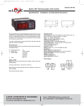
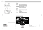
Dimensions (mm)
reverse
direct
PRG
mute
SEL
75
The new Universal Infrared instruments feature
exceptional characteristics:
• each controller comes complete with nine different
configured programs allowing you to set the regulation
program suitable to your application easily and quickly
(see inside page on this leaflet for further details);
• the majority of Infrared controllers are powered with
alternating or continuous 12/24 Volts. Additionally, there
are 110/230 Vac-dc models;
• all Infrared models come complete with 1 or 2 digital
inputs permitting straightforward alarm management
(even delayed alarms), set-point variation (via outside
clock or switch), remote ON-OFF, Cooling/Heating
switching, etc;
• all thermostats equipped with NTC sensor (thermistor)
can be connected to a second sensor to make your
instrument perform additional special functions.
64
71.5
1 2 3 4
direct
reverse
SEL
PRG
87
44
mute
88
The new Infrared Range comprises a series of different
models capable of satisfying the most demanding
application requirements:
• our instruments can be connected to the most common
temperature, humidity and pressure sensors available
on the market (NTC, Pt100, thermocouples type J or K,
0-20mA, 4-20mA, 0-1Vdc);
• the controllers are available with one, two, and now
also with four outputs, both in the 8A resistive
changeover relay versions and in the 10Vdc output
versions operating external Solid State Relays;
• you can choose between two different case models:
panel-mounted with front panel protection index IP65
and DIN-rail mounted models.
Temperature,
humidity,
pressure control?
TECHNICAL SPECIFICATIONS
33
Carel, leader in the production of controllers for more than
twenty years, is proud to introduce a new series of innovative
instruments specifically designed for the control of temperature, pressure, humidity in Air-Conditioning, Refrigeration
and Heating systems.
5 6 7 8
70
11
59.1
36
60
Inputs: depending on the model
Temperature: NTC, Pt100, thermocouples K/J
Current: 4/20 mA or 0/20 mA – voltage: -0.5/1 Vdc
Operating range:
NTC: -50÷90°C, Pt100: -100÷600°C,
TcK: -100÷999°C, TcJ: -100÷800°C
Current and voltage: -99/999
Resolution: 0.1 from -9.9 to 99.9 – 1 for different ranges
Precision: ± 0.5% of the range
Power supply:
Voltage:
IR32V, D, W, Z, A: 12/24 Vac-dc ±10%
IRDRV, W: 24 Vac ±10% and 220/240Vac ±10%
IRDRTE: 220/240Vac ±10% – IRDRZ and IRDRA: 12/24 Vac-dc, ±10%
Absorbed power:
IR32V: 2 VA – IR32W, Z: 3 VA
IRDRTE, IRDRV, IRDRW: 3 VA – IRDRZ: 4 VA
Operating temperature: 0÷50°C
Storage temperature: -10÷70°C
Ambient relative humidity: below 90% rH, non condensing
Ambient pollution: normal
Relay characteristics (all models): max. voltage 250Vac,
max. power 2000VA – max. initial current 10A
Signal features for Solid State Relay:
Output voltage: 10Vdc
Output res.: 660Ω
Max. output current: 15mA
Disconnection: type 1C according to ECC EN 60730-1 standards
Case: plastic, IR32 self-extinguishing standards according to UL94-VO
Series
the most advanced solution!
agency/distributor:
The Infrared Range can be programmed
in three ways: using the keypad of the
instrument itself, your Personal
Computer or a dedicated
exclusive remote control.
CAREL srl
Via dell’Industria, 11 - 35020
Brugine - Padova (Italy)
Tel. (+39) 049.9716611
Fax (+39) 049.9716600
http://www.carel.com
+302237336 rel. 2.0 del 10/02/99
Remote Control Unit
Advanced programming and supervision systems
In order to program your Infrared instruments, Carel has
designed Modì, a software specifically created to set any
working parameter easily via PC.
Any standard configuration filed in your PC can be easily
and quickly transmitted to the Infrared controllers via serial
line, thus avoiding any possible error that might occur when
programming them manually.
An incredible advantage, especially when you need to
program many controllers simultaneously.
As for supervision and telemaintenance services, Carel has
designed MasterPlant, the program running under Windows™
permitting supervision, monitoring and telemaintenance of
refrigeration and air-conditioning plants equipped with Carel
controllers. MasterPlant allows you to manage up to 800
instruments connected to a local and/or remote PC via
Modem. Among its numerous functions, MasterPlant allows
you to:
centralize on just one local and/or remote PC all the
operating parameters of showcases, display cabinets, walk-in
refrigerators, chillers, roof-top units, humidifiers, etc;
check all the operating parameters of the system via telephone
line and keep them under control on your PC, via modem; in
this way you will be able to control several plants located in
different geographical areas from a central station;
be informed immediately and automatically of any alarm,
via modem or fax. In the event of off-normal condition, a fax
can be sent to different operators;
file temperature, humidity, pressure values and possible
alarms as established by EU standards;
print graphs on customized forms.
List of operating parameters
Par. Description
St1
St2
C0
Set Point 1
Set Point 2
Mode of Operation (see inside page)
Selection of Differentials
P1
Differential of Set Point 1
P2
Differential of Set Point 2
P3
Dead zone differential
C4
Authority for Set Point offset
C5
Type of control action (Proportional, P+I)
Outputs
C6
Time-delay between energization of 2
different relays
C7
Min. time between energizations of the
same relay
C8
Min. disenergization time of the relay
C9
Min. energization time of the relay
C10 Relay status in the event of sensor alarm:
0 = all relays disenergized
1 = all relays energized
2 = Relays in Direct energized, disenergized
the others
3 = Relays in Reverse energized,
disenergized the others
C11 Output rotation
0 = no rotation
1 = standard rotation
2 = rotation of capacity-controlled compressors
3 = as above with N.O. valves
C12 Time interval in PWM mode
Sensor
C13 Type of sensor
P14 Sensor calibration
C15 Min. value for input I and V
C16 Max. value for input I and V
C17 Anti-noise filter
C18 Temperature unit selection: 0=°C, 1=°F
Optional Modules
The IR32A, IR32D and IRDRA models, complete with
voltage outputs for Solid State Relays, can be successfully used to manage complex systems equipped
with several ON/OFF or Proportional devices.
The Infrared Series, in fact, can be equipped with
optional modules allowing instrument to convert the
signal of the output into a proportional signal (0-10 Vdc
or 4-20 mA) or an ON/OFF signal (10 A res. relay).
Just one single IR32A or IRDRA can manage up to
four optional modules!
C19
Second sensor (models for NTC only)
1 = differential operating mode
2 = summer offset
3 = winter offset
4 = neutral-zone offset
Set-Point
C21 Min. value Set-point 1
C22 Max. value Set-point 1
C23 Min. value Set-point 2
C24 Max. value Set-point 2
Alarm parameters
P25 Low temperature set-point alarm
P26 High temperature set-point alarm
P27 Alarm differential
P28 Time-delay before alarm starts
C29 Digital input 1
0 = idle input
1 = immediate external alarm, automatic
reset
2 = immediate external alarm, manual reset
3 = delayed external alarm (P28)
4 = ON/OFF
C30 Second digital input management
C31 Output status in the event of alarm condition
via digital input: same options as C10
Further settings
C32 Serial connection address
C50 Keypad (TS) and Remote Control (TC)
management
0 = TS OFF, TC ON (type P parameters only)
1 = TS ON, TC ON (type P parameters only)
2 = TS OFF, TC OFF
3 = TS ON, TC OFF
4 = TS ON, TC ON (any parameter)
C51 Code to activate the remote control unit
Modes of operation
Setting parameters is a really simple operation as each Infrared instrument comes
complete with nine factory-set modes of operation to suit any application requirement.
In order to select one of the nine Modes, all you have to do is just set only one
parameter: the controller will automatically load all the values associated to the
chosen Mode.
6) DIRECT/REVERSE switching via digital input. Applications: Air-Conditioning units,
especially those having a cooling/heating operating mode (heat pumps, fan coils, etc.). The
instrument works with two different parameter lists (set-point and differential), one for cooling,
the other for heating. Switching the working mode and the working set-point is a completely
automatic operation (via digital input through a switch or a clock).
mod. V
OUT 1
OUT 2
OUT 1
OUT 2
D
D
D
D
D
Diff.(P1)
For further information see the descriptions below.
OUT 3
D
OUT 4
D
Diff.(P1)
Diff.(P1)
Set (St 1)
For more experienced operators a tenth mode of operation is also available so as to
combine the nine modes with further functions of the Infrared Series and get new
algorithms. For more information ask for the Infrared Series User Manual (code
+030220160) your distributor or Carel (fax: +39 49.9716600).
mod. Z
mod. W
OUT 1
Set (St 1)
Set (St 1)
DIGITAL INPUT OPENED
mod. V
mod. Z
mod. W
OUT 1
OUT 2
OUT 1
OUT 4
OUT 3
R
R
R
R
R
Diff.(P2)
OUT 2
R
OUT 1
R
Diff.(P2)
Diff.(P2)
Set (St 2)
Set (St 2)
Set (St 2)
DIGITAL INPUT CLOSED
1) DIRECT mode of operation. Applications: Refrigeration and Air-Conditioning sectors
(control of chillers, compressor packs, etc.). When the controlled parameter increases,
the instrument actuates a control sequence so as to reduce its value and reach the
set-point (desired performance).
mod. V
mod. Z
mod. W
OUT 1
OUT 1
OUT 2
OUT 1
OUT 2
D
D
D
D
D
Diff.(P1)
D
OUT 4
D
Diff.(P1)
Diff.(P1)
Set (St 1)
OUT 3
7 and 8) DIRECT/REVERSE mode of operation with set-point and differential change via
digital input. These modes of operation are similar to modes 1 and 2. Modes 7 and 8 allow
your instrument to work with two different set-points and differentials so as to modify operation
during the day and the night, or more generally, to optimize energy requirements.
The parameters are modified via digital input through a switch or an external clock.
The type of control action – Direct in mode 7 (showed in the figure below) and Reverse in
mode 8 – does not change. Particularly useful for chillers, condensation units, etc.
Set (St 1)
Set (St 1)
mod. V
2) REVERSE mode of operation. Applications: Heating and Air-Conditioning sectors
(control of heaters, heat pumps, etc.). When the controlled parameter decreases, the
instrument actuates a control sequence so as to increase the value of the parameter
up to the set-point.
OUT 1
OUT 2
OUT 1
OUT 2
D
D
D
D
D
Diff.(P1)
Set (St 1)
mod. W
OUT 2
OUT 1
R
mod. Z
OUT 1
R
OUT 4
R
Diff.(P1)
OUT 2
OUT 3
R
R
R
Diff.(P1)
D
Set (St 1)
Set (St 1)
DIGITAL INPUT OPENED
mod. Z
mod. W
OUT 1
OUT 2
OUT 1
OUT 2
OUT 1
D
D
D
D
D
R
Diff.(P2)
Set (St 2)
Set (St 1)
OUT 3
OUT 4
D
D
Diff.(P2)
Diff.(P2)
Set (St 2)
Set (St 2)
DIGITAL INPUT CLOSED
3 and 4) DEAD ZONE mode of operation. Applications: Air-Conditioning, seasoning,
etc. The controller responds to any deviation from the set-point, forcing the value of the
controlled parameter within a specific range (dead zone). In the PWM mode (mode 4)
the time necessary for the outputs to energize depends on the deviation from the
set-point. In this case we suggest using models 'A' and 'D' for Solid State Relays.
9) 2 SET-POINTS mode, one in Direct, the other in Reverse. This mode of operation is
available only in 2-output (W) or 4-Output (Z/A) models. Half of the outputs energize in the
Direct mode, the other half in the Reverse. The two set-points are independent.
This mode of operation allows you to control your equipment as if you had two different
instruments connected to the same sensor.
mod. W
OUT 1
mod. V
mod. W
OUT 1
R
Diff.(P1)
(P3)
(P3)
D
Diff.(P1)
D
R
(P3)
OUT 2
R
OUT 2
OUT 1
Diff.(P1)
OUT 4
Diff.(P1)
OUT 1
Diff.(P1)
Set (St 1)
Set (St 1)
OUT 3
D
Diff.(P1)
mod. V
mod. V
mod. Z
mod. W
OUT 1
Diff.(P2)
Set (St 2)
Set (St 1)
Diff.(P2)
Neutral zone
mod. Z
Neutral zone
Set (St 1)
Set (St 1)
OUT 2
OUT 1
OUT 3
OUT 4
R
R
D
D
mod. Z
OUT 2
OUT 3
OUT 1
R
OUT 4
D
R
(P3)
Diff.(P1)
(P3)
Diff.(P2)
Set (St 2)
Diff.(P1)
Set (St 1)
D
Diff.(P2)
Set (St 1)
Neutral zone
Set (St 1)
Wiring diagrams.
The wiring diagram below as example refers to the IR32Z model for NTC, PT100, TC J/K or V/I
probes.
Important: each instrument should be connected to a specific sensor.
For further details contact your nearest agent.
OUT 3
5) ALARM mode of operation. This mode of operation allows you to get a complete
alarm management. In 4-output models, for example, two outputs can be used to make
the instrument perform control action within the dead zone and the other two can be
used to manage high and low (temperature) alarms.
mod. V
1
(P3)
Diff.(P27)
Neutral zone
High/Low Alarm
Diff.(P1)
Diff.(P27)
(P25/P26)
Set (St 1)
(P25/P26)
OUT 1
Diff.(P27)
Diff.(P1)
1
OUT 2
4
(P3)
Diff.(P2)
Low Alarm
Neutral zone
Set (St 1)
6
7 8
9
COM DIG.IN
3
4
-
+
12-24 V
3 VA
Diff.(P27)
1
7
(P25)
5
5
6
7
8 9
OUT 4
D
R
DIG.IN COM NTC1 NTC2
_
12-24 V ~
3 VA
POWER
2
OUT 1
(P3)
3
c
mod. Z
OUT 3
2
OUT 1
R
High/Low Alarm
POWER
SERIAL
LINK
c
c
c
OUT 2
OUT 1
13 14 15 16 17 18
c
mod. W
OUT 1
OUT 4
OUT 2
10 11 12
High Alarm
(P26)
2
8
3
9
Pt100
7
_
8
9
TcJ/K
+
7
M
8
9
+10
V/I
OUT