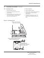
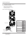
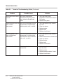
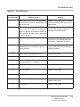
1
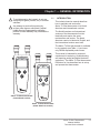
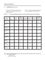
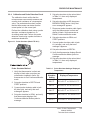
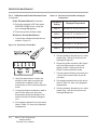
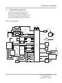
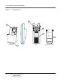
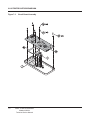
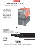
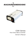
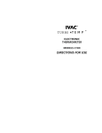
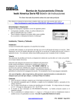
Technical Service Manual
Alaris® Tri-Site Thermometer
Models 228XXX
May 2006
Alaris® Products
General Contact Information
Cardinal Health
Alaris® Products
Cardinal Health
The Crescent, Jays Close
Basingstoke, Hampshire, RG22 4BS,
United Kingdom
http://www.cardinalhealth.co.uk/alaris
10221 Wateridge Circle
San Diego, California 92121
USA
http://www.cardinal.com/alaris
Customer Advocacy
Clinical and technical feedback.
North America:
Phone: 800.854.7128, Ext. 7812
E-Mail: [email protected]
International:
E-Mail: [email protected]
Technical Support - North America
Maintenance, service information support, and troubleshooting.
United States:
Phone:
858.458.6003
800.854.7128, Ext. 6003
Canada:
Phone:
Eastern: 800.387.8309
Western: 800.387.8309
Customer Care - North America only
Instrument return, service assistance, and order placement.
United States:
Phone: 800.482.4822
Canada:
Phone: 800.387.8309
Technical and Customer Services - UK only
Maintenance and service information support.
Instrument return, service assistance, and order placement.
Customer Service:
Freephone: 0800 917 8776
E-Mail: [email protected]
Technical Service:
Freephone: 0800 389 6972
E-Mail: [email protected]
International Service Contacts
For service or technical information, contact the nearest Cardinal Health Affiliate Office,
your local representative, or see: http://www.alarismed.co.uk/technical/contacts.html
Alaris® Tri-Site Thermometer
Models 228XXX
Technical Service Manual
TABLE OF CONTENTS
Chapter 1 - General Information
1.1
Introduction . . . . . . . . . . . . . . . . . . . . . . . . . . . . . . . . . . . . . . . . . . . . . . . . . . . . . . . . . . . . . . . . . . . . . . . . . . . . . . . . . . . . . . . . . . . .
1-1
1.2
Warning Definitions . . . . . . . . . . . . . . . . . . . . . . . . . . . . . . . . . . . . . . . . . . . . . . . . . . . . . . . . . . . . . . . . . . . . . . . . . . . . . . . . . . .
1-3
1.3
Specifications
1-3
1.4
Operating Features, Controls and Indicators
1.5
Accessories
1.6
Customer and Technical Service
.........................................................................................
.......................................................
1-3
...........................................................................................
1-3
....................................................................
1-3
Chapter 2 - Checkout and Configuration
2.1
Introduction . . . . . . . . . . . . . . . . . . . . . . . . . . . . . . . . . . . . . . . . . . . . . . . . . . . . . . . . . . . . . . . . . . . . . . . . . . . . . . . . . . . . . . . . . . . .
2-1
2.2
New Instrument Checkout
2-1
2.3
Changing Factory Default Settings
2.3.1
Mode and Scale
2.3.2
Anti-Theft Timer Interval
...........................................................................
..................................................................
2-2
......................................................................................
2-2
.............................................................................
2-2
Chapter 3 - Preventive Maintenance
3.1
Introduction . . . . . . . . . . . . . . . . . . . . . . . . . . . . . . . . . . . . . . . . . . . . . . . . . . . . . . . . . . . . . . . . . . . . . . . . . . . . . . . . . . . . . . . . . . . .
3-1
3.2
Preventive Maintenance
.............................................................................
3-1
3.2.1
Visual Inspection . . . . . . . . . . . . . . . . . . . . . . . . . . . . . . . . . . . . . . . . . . . . . . . . . . . . . . . . . . . . . . . . . . . . . . . . . . . . . . . . . . . . . .
3-2
3.2.2
Startup Check . . . . . . . . . . . . . . . . . . . . . . . . . . . . . . . . . . . . . . . . . . . . . . . . . . . . . . . . . . . . . . . . . . . . . . . . . . . . . . . . . . . . . . . . .
3-2
3.2.3
Pulse Timer Check
...................................................................................
3-2
3.2.4
Calibration and Probe Detection Check . . . . . . . . . . . . . . . . . . . . . . . . . . . . . . . . . . . . . . . . . . . . . . . . . . . . . . . . . . . . .
3-3
3.2.5
Probe Simulator Calibration Verification
............................................................
3-5
3.3
Cleaning
...............................................................................................
3-5
3.3.1
Cleaning Thermometer Buttons
.....................................................................
3-5
4.1
Introduction . . . . . . . . . . . . . . . . . . . . . . . . . . . . . . . . . . . . . . . . . . . . . . . . . . . . . . . . . . . . . . . . . . . . . . . . . . . . . . . . . . . . . . . . . . . .
4-1
4.2
Operation Overview
4-1
4.3
Continuous Measurement Method
4.4
Chapter 4 - Principles of Operation
..................................................................................
..................................................................
4-2
Fast Measurement Method
..........................................................................
4-2
4.5
Thermometer Subsystems
...........................................................................
4-3
4.5.1
Microcomputer
........................................................................................
4-4
4.5.2
DC Power Regulation
4.5.3
Thermometer Probe Operation
......................................................................
4-4
4.5.4
Liquid Crystal Display (LCD) Operation . . . . . . . . . . . . . . . . . . . . . . . . . . . . . . . . . . . . . . . . . . . . . . . . . . . . . . . . . . . . .
4-5
4.5.5
Thermometer Audio
..................................................................................
4-5
4.5.6
Anti-Theft Feature
....................................................................................
4-5
................................................................................
Alaris® Tri-Site Thermometer
Models 228XXX
Technical Service Manual
4-4
i
TABLE OF CONTENTS
Chapter 5 - Corrective Maintenance
5.1
Introduction . . . . . . . . . . . . . . . . . . . . . . . . . . . . . . . . . . . . . . . . . . . . . . . . . . . . . . . . . . . . . . . . . . . . . . . . . . . . . . . . . . . . . . . . . . . .
5-1
5.2
Disassembly/Resassembly
..........................................................................
5-2
5.2.1
Opening the Case
....................................................................................
5-3
5.2.2
Anti-Theft Timer Configuration . . . . . . . . . . . . . . . . . . . . . . . . . . . . . . . . . . . . . . . . . . . . . . . . . . . . . . . . . . . . . . . . . . . . . . .
5-4
5.2.3
Circuit Board
..........................................................................................
5-5
5.2.4
Probe Wells
...........................................................................................
5-6
Chapter 6 - Troubleshooting
6.1
Introduction . . . . . . . . . . . . . . . . . . . . . . . . . . . . . . . . . . . . . . . . . . . . . . . . . . . . . . . . . . . . . . . . . . . . . . . . . . . . . . . . . . . . . . . . . . . .
6-1
6.2
Self-Test . . . . . . . . . . . . . . . . . . . . . . . . . . . . . . . . . . . . . . . . . . . . . . . . . . . . . . . . . . . . . . . . . . . . . . . . . . . . . . . . . . . . . . . . . . . . . . .
6-1
Chapter 7 - Illustrated Parts Breakdown
ii
7.1
Introduction . . . . . . . . . . . . . . . . . . . . . . . . . . . . . . . . . . . . . . . . . . . . . . . . . . . . . . . . . . . . . . . . . . . . . . . . . . . . . . . . . . . . . . . . . . . .
7-1
7.2
Illustrations
............................................................................................
7-1
7.3
Parts List
..............................................................................................
7-1
7.4
Ordering Parts
........................................................................................
Alaris® Tri-Site Thermometer
Models 228XXX
Technical Service Manual
7-1
TABLE OF CONTENTS
List of Tables
1-1
Thermometer Models/Versions Covered by this Service Manual
3-1
Probe Simulator Settings/Displayed Temperatures
3-2
Resistance Decade Box/Displayed Temperatures
3-3
Probe Simulator Verification
5-1
Required Materials, Supplies and Tools
5-2
Level of Testing Guidelines
6-1
Technical Troubleshooting Guide
6-2
Error Messages
7-1
Parts List
.................................
1-2
................................................
3-3
.................................................
3-4
.........................................................................
3-5
............................................................
5-2
..........................................................................
5-7
...................................................................
6-2
.......................................................................................
6-5
..............................................................................................
7-2
List of Figures
3-1
Probe Simulator
3-2
Resistance Decade Box
3-3
Probe Simulator Cable Plug
4-1
Block Diagram
5-1
Opening the Case
5-2
Anti-Theft Jumper Configuration
....................................................................
5-4
5-3
Circuit Board
.........................................................................................
5-5
5-4
Probe Wells
..........................................................................................
5-6
7-1
Label Placement
7-2
Front/Rear Case, Battery Compartment
7-3
Circuit Board Assembly
7-4
Accessories
......................................................................................
.............................................................................
3-3
3-4
.........................................................................
3-5
........................................................................................
4-3
....................................................................................
......................................................................................
5-3
7-4
............................................................
7-5
..............................................................................
7-6
...........................................................................................
7-7
Alaris® Tri-Site Thermometer
Models 228XXX
Technical Service Manual
iii
TABLE OF CONTENTS
T H I S PA G E
I N T E N T I O N A L LY
LEFT BLANK
iv
Alaris® Tri-Site Thermometer
Models 228XXX
Technical Service Manual
1
GENERAL INFORMATION
Chapter 1 — GENERAL INFORMATION
!
!
To avoid damaging the keypad, do not use
sharp objects (pens, pencils, etc.) to activate
switches.
1.1
Any attempt to service this product by
anyone other than an authorized Cardinal
Health Service Representative while the
product is under warranty may invalidate the
warranty.
INTRODUCTION
This technical service manual describes
how to maintain and service the
Alaris® Tri-Site thermometer in its North
American and International versions.
The North American and international
versions of the thermometer function
identically and require the same
maintenance and service. The North
American version is labeled in English, and
the international version uses icons.
The Alaris® Tri-Site thermometer is available
in nine models (see Table 1-1) and uses
only P850A disposable probe covers.
This manual is intended for personnel
experienced in analyzing, troubleshooting
and repairing analog and digital electronic
equipment. The Alaris® Tri-Site thermometer
Directions for Use describes how to set up
and operate the thermometer.
Alaris® Tri-Site thermometer
(International version)
Alaris® Tri-Site thermometer
(North American version)
Alaris® Tri-Site Thermometer
Models 228XXX
Technical Service Manual
1-1
GENERAL INFORMATION
1.1
INTRODUCTION (Continued)
The Alaris® Tri-Site thermometer includes a
thermometer, a home base, probes, and
attachment options.
Table 1-1.
Thermometer Models/Versions Covered by this Technical Service Manual
Model/
version
Portable
Wall
Mount
Oral/
Axillary
Rectal Only
Probe (blue) Probe (red)
2280OR (North
America)
X
X
2280O (North
America)
X
X
2280R (North
America)
X
2285OR (North
America)
X
X
2285O (North
America)
X
X
2285R (North
America)
X
2281OR
(International)
X
X
2281O
(International)
X
X
2281R
(International)
X
1-2
Table 1-1 summarizes thermometer package
contents according to model and version:
Alaris® Tri-Site Thermometer
Models 228XXX
Technical Service Manual
Home
Base
Carrying
Strap
Probe
Cover
Dispenser
X
X
X
X
X
X
X
X
X
X
X
X
X
X
X
X
X
X
X
X
X
X
X
X
X
X
X
X
X
X
GENERAL INFORMATION
1.2
WARNING DEFINITIONS
Refer to the Alaris® Tri-Site thermometer
DFU.
1.3
SPECIFICATIONS
Refer to the Alaris® Tri-Site thermometer
DFU.
1.4
OPERATING FEATURES, CONTROLS
AND INDICATORS
Refer to the Alaris® Tri-Site thermometer
DFU.
1.5
ACCESSORIES
Refer to the Alaris® Tri-Site thermometer
DFU.
1.6
CUSTOMER AND TECHNICAL
SERVICE
Refer to “General Contact Information” at
the front of this manual.
Alaris® Tri-Site Thermometer
Models 228XXX
Technical Service Manual
1-3
GENERAL INFORMATION
T H I S PA G E
I N T E N T I O N A L LY
LEFT BLANK
1-4
Alaris® Tri-Site Thermometer
Models 228XXX
Technical Service Manual
2
CHECKOUT & CONFIGURATION
Chapter 2 — CHECKOUT AND CONFIGURATION
2.1
!
INTRODUCTION
This chapter describes initial setup and
configuration for the Alaris® Tri-Site
thermometer. Due to product changes over
time, configurations described in this chapter
may differ from the instrument being
serviced.
Remove the thermometer from use
immediately if it is dropped or severely
jarred. Qualified service personnel must
thoroughly test and inspect the
thermometer before returning to use.
2.2
NEW INSTRUMENT CHECKOUT
Refer to the thermometer Directions for Use
(DFU) for instructions regarding unpacking
and setup for first time use.
At power up verify the that the thermometer
beeps and all LCD elements flash. This
confirms that the thermometer has passed
its self test and is operating correctly. The
thermometer continually performs a self test
during operation and alarms and displays a
message if it detects an internal malfunction.
Alaris® Tri-Site Thermometer
Models 228XXX
Technical Service Manual
2-1
CHECKOUT AND CONFIGURATION
2.3
CHANGING FACTORY DEFAULT
SETTINGS
2.3.1
Mode and Scale
The thermometer factory default settings for
mode and temperature scale are Fast Oral
mode, Fahrenheit (°F) temperature scale.
To change the default settings:
1. Press Pulse Timer button for 15 seconds
(until LCD display test begins).
2. To change default settings:
Press the Mode button until the screen
displays the desired mode.
Press the Recall/Temperature Scale
button until the screen displays the
desired temperature scale.
3. Press Pulse Timer button or remove
probe from well to save the new default
settings.
2.3.2
Anti-Theft Timer Interval
Refer to “Anti-Theft Timer Configuration” in
Chapter 5 (Corrective Maintenance).
2-2
Alaris® Tri-Site Thermometer
Models 228XXX
Technical Service Manual
!
Thermometer settings revert to default
values following battery replacement.
Qualified hospital/facility personnel must
ensure that hospital-approved default
settings are selected.
3
PREVENTIVE MAINTENANCE
Chapter 3 — PREVENTIVE MAINTENANCE
!
Failure to perform regular and preventive
maintenance inspections may result in
improper thermometer operation.
3.1
INTRODUCTION
Perform regular and preventive
maintenance inspections to ensure that the
thermometer remains in good operating
condition:
• Perform regular inspections for damage
and cleanliness before each use as
described in the Alaris® Tri-Site
thermometer DFU.
• Perform preventive maintenance
inspections annually.
These requirements and guidelines are
intended to complement the intent of Joint
Commission on Accreditation of Healthcare
Organizations (JCAHO) requirements.
Electrical safety tests are not required for
battery-powered devices.
3.2
PREVENTIVE MAINTENANCE
Qualified service personnel must perform
these periodic maintenance procedures
annually:
• Visual inspection (section 3.2.1).
• Startup check (section 3.2.2).
• Pulse timer check (section 3.2.3).
• Calibration check (section 3.2.4).
• Probe simulator calibration, if applicable
(section 3.2.5).
Cardinal Health offers service agreements
for performing required periodic inspections.
3.2.1
Visual Inspection
Check the case, display, and probes for
damage and cleanliness. (Section 3.3
describes how to clean the thermometer).
Alaris® Tri-Site Thermometer
Models 228XXX
Technical Service Manual
3-1
PREVENTIVE MAINTENANCE
3.2.2
Startup Check
Backlight Test
The Startup Check includes a power-on test,
functional test, backlight test, and display
test.
1. Use black tape to cover hole above
LCD.
2. Press and release Pulse Timer button,
then verify that backlight is on.
Power-On Test
3. Press and release Pulse Timer button
again, then verify that backlight is off.
1. Install batteries into thermometer.
2. Verify that the screen displays all
segments, then beeps and displays the
Return to Base symbol or message.
4. Remove black tape.
Display Test
3. Return thermometer to home base.
1. Press and hold Pulse Timer button for
15 seconds, until the LCD displays the
software revision.
4. Verify that beeping stops and display is
blank.
2. Release Pulse Timer button. Display test
begins within 2 seconds: verify that each
segment flashes.
Functional Test
1. Insert an oral probe into the blue well.
Insert the connector into jack #2.
3. Press and briefly hold Pulse Timer
button to exit test and turn thermometer
off.
2. Remove probe from storage well.
3. Verify that the instrument beeps once
and that all segments except the Pulse
Timer clock momentarily turn on.
Pulse Timer Check
4. When this sequence is complete (1 to 2
seconds), verify that the instrument
displays the Fast Oral Mode symbol or
message.
1. Press and hold Pulse Timer button for
one second. Verify that a short beep
sounds and the 12-segment timer
symbol appears.
5. Verify that no alarms occur for 10
seconds, then return probe to well.
2. Verify that one segment disappears
every five seconds.
6. Verify that thermometer beeps once and
display is blank.
3. Verify that thermometer beeps:
• once at 15 seconds
• twice at 30 seconds
• three times at 60 seconds
7. Verify that no alarms occur for 30
seconds (thermometer automatically
tests heater interlock circuits).
8. If applicable, repeat procedure for rectal
probe (insert into red well and connect to
jack #1).
3-2
3.2.3
Alaris® Tri-Site Thermometer
Models 228XXX
Technical Service Manual
4. Press Pulse Timer button to stop timer
operation at any time: verify that
thermometer beeps three times and
timer symbol turns off.
PREVENTIVE MAINTENANCE
3.2.4
Calibration and Probe Detection Check
The calibration check verifies that the
microprocessor can correctly measure and
convert circuit resistance to a temperature
value. The probe detection check verifies
that the thermometer can detect that the
correct probe is in the correct jack.
Perform the calibration check using a probe
simulator, resistance decade box, or
circulating water bath. Perform the probe
detection check using a probe simulator or
resistance decade box.
Figure 3-1. Probe Simulator (Model TE 1811)
5. Set probe simulator to the values listed
in Table 3-1, then verify displayed
temperatures.
6. Set probe simulator to BP, then press
BROKEN PROBE button. Verify that
error message 67 appears.
7. Disconnect probe simulator cable. Again
verify that thermometer is silent and
display is blank. Set thermometer to
Rectal Continuous/Monitor mode.
8. Set probe simulator to ORAL and
START positions.
9. Connect probe simulator cable to jack
#1 (red side), and verify that error
message 3 appears.
10. Set probe simulator to RECTAL.
11. Verify that thermometer displays Rectal
Continuous/Monitor Mode symbol or
message.
12. Set probe simulator to the values listed
in Table 3-1, then verify displayed
temperatures.
Probe Simulator Method
1. Verify that thermometer is silent and
display is blank when no probes are
connected or installed in wells. Set
thermometer to Oral Continuous/Monitor
mode.
2. Set probe simulator to RECTAL and
START positions.
3. Connect probe simulator cable to jack
#2 (blue side), and verify that error
message 3 appears.
4. Set probe simulator to ORAL, and verify
that thermometer displays Oral
Continuous/Monitor Mode symbol or
message.
Table 3-1. Probe Simulator Settings/ Displayed
Temperature
Probe
Simulator
Setting
Displayed Temperature
80.2 oF
80.2 ± 0.2 oF or 26.8 ± 0.1 oC
98.0 oF
98.0 ± 0.2 oF or 36.7 ± 0.1 oC
98.6 oF
98.6 ± 0.2 oF or 37.0 ± 0.1 oC
102.0 oF
102.0 ± 0.2 oF or 38.9 ± 0.1 oC
107.8 oF
107.8 ± 0.2 oF or 42.1 ± 0.1 oC
Alaris® Tri-Site Thermometer
Models 228XXX
Technical Service Manual
3-3
PREVENTIVE MAINTENANCE
3.2.4 Calibration and Probe Detection Check
(Continued)
Probe Simulator Method (Continued)
13. Set probe simulator to BP, then press
BROKEN PROBE button. Verify that
error message 68 appears.
Table 3-2. Resistance Decade Box/ Displayed
Temperature
Resistance
Setting
Displayed Temperature
6097 Ω
98.0 ± 0.2 oF or 36.7 ± 0.1 oC
9254 Ω
80.2 ± 0.2 oF or 26.8 ± 0.1 oC
6015 Ω
98.6 ± 0.2 oF or 37.0 ± 0.1 oC
5570 Ω
102.0 ± 0.2 oF or 38.9 ± 0.1 oC
4895 Ω
107.8 ± 0.2 oF or 42.1 ± 0.1 oC
14. Disconnect probe simulator cable.
Resistance Decade Box Method
1. Connect the resistance decade box as
shown in Figure 3-2.
Figure 3-2. Resistance Decade Box
5. Set the resistance decade box to a value
greater than 1 MΩ and verify that error
message 67 appears.
6. Disconnect probe simulator cable. Again
verify that thermometer is silent and
display is blank. Set thermometer to
Rectal Continuous/Monitor mode.
2. Verify that thermometer is silent and
display is blank when no probes are
connected or installed in wells. Set
thermometer to Oral Continuous/Monitor
mode.
3. Connect resistance decade box cable to
jack #2 (blue side), and verify that
thermometer beeps and displays Oral
Monitor/Continuous Mode message or
icon.
4. Set resistance decade box to the values
listed in Table 3-2, then verify displayed
temperatures.
3-4
Alaris® Tri-Site Thermometer
Models 228XXX
Technical Service Manual
7. Connect jumper between connector pins
1 and 6, then connect cable to jack #1
(red side).
8. Set resistance decade box to the values
listed in Table 3-2, then verify displayed
temperatures.
9. Set the resistance decade box to a value
greater than 1 MΩ and verify that error
message 68 appears.
PREVENTIVE MAINTENANCE
3.2.4 Calibration and Probe Detection Check
(Continued)
3. The probe simulator fails if measured
values are not within specified ranges.
Circulating Water Bath Method
1. While pressing and holding the pulse
timer button, remove a probe from the
probe well. Release the pulse timer
button.
Table 3-3. Probe Simulator Verification
Probe Simulator Setting Multimeter Reading
80.2
9250 to 9258
98.0
6093 to 6101
98.6
6011 to 6019
102.0
5566 to 5574
107.8
4891 to 4899
BP and BROKEN
PROBE button pressed
Open circuit
2. Verify that thermometer displays Oral or
Rectal Continuous/Monitor Mode symbol
or message.
3. Install a probe cover over the probe and
insert the probe 2.5 to 3 inches into
water bath.
4. Leave probe in place for at least two
minutes.
3.3
5. Verify that displayed temperature is
within ±0.2 oF (±0.1 oC ) of actual water
temperature.
3.2.5 Probe Simulator Calibration
Verification
Verify calibration of the probe simulator (if
used) annually. Verification requires a
FLUKE Multimeter Model 8800A or
equivalent 5 1/2 digit meter.
1. Set multimeter to K OHMS, RANGE 20.
2. Measure between pins 2 and 3 of the
probe simulator plug (Figure 3-3), then
verify resistance measurements (Table
3-3).
Figure 3-3. Probe Simulator Cable Plug
CLEANING
Qualified service personnel must clean
thermometer buttons as required. Refer to
the Alaris® Tri-Site thermometer DFU for all
other cleaning instructions.
3.3.1
Cleaning Thermometer Buttons
Clean thermometer buttons periodically:
dried matter under buttons can affect
response to button presses. To clean button
pad:
1. Remove batteries and screws that
attach front and back of thermometer,
then remove front case.
2. Gently remove button pad from front
case, and inspect for damage. If any
damage is visible, replace before
returning device to use.
3. Use an approved cleaning solution to
clean as necessary.
4. Reassemble button pad into front case,
align locator pins and cutouts to ensure
correct position.
5. Replace screws to attach front and back
of thermometer, then replace batteries.
Alaris® Tri-Site Thermometer
Models 228XXX
Technical Service Manual
3-5
PREVENTIVE MAINTENANCE
T H I S PA G E
I N T E N T I O N A L LY
LEFT BLANK
3-6
Alaris® Tri-Site Thermometer
Models 228XXX
Technical Service Manual
4
PRINCIPLES OF OPERATION
Chapter 4 — PRINCIPLES OF OPERATION
4.1
INTRODUCTION
This chapter describes the principles of
operation for the Alaris® Tri-Site thermometer
and its major subsystems.
4.2
OPERATION OVERVIEW
The Alaris® Tri-Site thermometer uses a
thermistor in the tip of the probe to sense
temperature. Temperature changes cause
an inverse, nonlinear change in thermistor
resistance.
The thermistor’s output voltage represents
the measured temperature, and is fed to the
thermometer’s microcomputer. The
microcomputer then drives the thermometer
screen to display the temperature.
Temperature calculations differ according to
whether the Continuous or Fast (predictive)
method is in use. Either method can be
used at any of three body sites (oral, axillary,
or rectal). The combination of measurement
method and body site is called the mode.
System power up begins when batteries are
installed in the thermometer (once batteries
are installed, the thermometer alarms until it
is returned to home base).The thermometer
performs self tests of its RAM, ROM, LCD,
reference voltages, audio system, battery
voltage, and anti-theft feature. If self testing
does not complete within an expected time
limit, the thermometer alarms.
Once self testing is complete, the
thermometer continuously checks its status
and alarms if an error is detected. Operator
inputs to the thermometer include button
presses, connecting probes to the
thermometer, and installing and removing
probes.
Alaris® Tri-Site Thermometer
Models 228XXX
Technical Service Manual
4-1
PRINCIPLES OF OPERATION
4.3
CONTINUOUS MEASUREMENT
METHOD
During the Continuous measurement
method, the thermometer’s microcomputer
converts data from the probe directly to a
temperature and displays it in the selected
temperature scale (celsius or fahrenheit).
A continuous temperature reading generally
takes 3 - 5 minutes to stabilize, and the
displayed temperature reflects the current
measurement as long as the probe is not in
its probe well. This method is used for
continuous temperature measurements that
last less than an hour, or when the
thermometer cannot calculate a temperature
using the Fast method.
4.4
FAST MEASUREMENT METHOD
During the Fast (predictive) measurement
method, the thermometer applies power to a
heating element in the probe tip to allow the
probe to reach a predefined target
temperature that is close to the temperature
at the body site.
The thermometer’s first measurement
verifies that ambient temperature is within
the specified operating range (16.0 to
33.3°C or 60.8 to 92°F). If not, the
thermometer exits the Fast method and
uses the Continuous method.
4-2
Alaris® Tri-Site Thermometer
Models 228XXX
Technical Service Manual
If the thermometer switches to the
Continuous method, one long beep and a
changed mode indicator signal the change.
The thermometer also uses the Continuous
method if the final predicted temperature is
below 35°C (95°F) or above 41°C (106°F),
or if it cannot complete the temperature
prediction within 22 seconds (oral/rectal
temperatures) or 30 seconds (axillary
temperatures).
When probe temperature reaches 34°C
(94°F), the thermometer assumes that
tissue contact is established and displays
the tissue contact indicator. When probe
temperature rises above the predefined
target, the heater shuts off.
Once the heater shuts off, the thermometer
computes an estimate of the steady state
temperature by sampling temperature every
100 milliseconds and comparing it to a
theoretical curve. This technique allows the
Fast method to estimate a temperature
within seconds, without having to wait
several minutes for the probe's thermistor tip
to reach the same temperature as the
tissue. When the thermometer reaches a
final estimate, it beeps three times and
displays the temperature for 45 seconds or
until the probe is reinserted into its well.
PRINCIPLES OF OPERATION
4.5
THERMOMETER SUBSYSTEMS
This section describes subsystems of the
Alaris® Tri-Site thermometer, including
microcomputer, DC power regulation, probe,
LCD, audio, and anti-theft timer. Figure 4-1
shows a block diagram of the thermometer.
Figure 4-1. Block Diagram
Y1
32.768kHz
Y2
5.00MHz
U9 5 Volt Boost
Converter
SHUTDOWN3*
+5 V
VBATT
D3
Q1
V BATT
RESET*
+5vsw
+5 V
System
Reset
U8
CR2
Not Installed
SHUTDOWN2
U5 5 Volt
Boost
Converter
3 AA
Cells
SHUTDOWN1
Anti-Theft
Sensor
S3
ANTI_THEFT_REED
N
S
BATT_MONITOR
+5vsw
SCLK
Probe A/D
Converter
U7
THERMISTOR1
+5vsw
ADC_CLK
ADC_DATA_IN
ADC_DATA_OUT
VREF2.50
THERMISTOR2
Ambient
Light
Detector
LDR1
AMBIENT_LIGHT
ADC_DATA_RDY*
VREF 2.5
vdc
VREF2.50
Function
Array
PROBE_INSTALLED1
PROBE_INSTALLED2
Rectal Probe
uCONTROLLER
HEATER_PWM
HEATER1_ENABLE
U6
+5vsw
HEATER2_ENABLE
LCD
Bias
Network
RE_TRIGGER1
Probe Interface
U2,U3
RE_TRIGGER2
HEATER_DETECT
LED Backlight DS2
HEATER_DR (Not Used)
BACKLIGHT_STROBE
Oral Probe
Backlight
Driver Q4
+5 V
Pulse
Timer
HEATER_DR2
S0 - S22
Liquid Crystal Display
DS1
PULSE_TIMER
o
HEATER_DETECT
TEMP_SCALE
HEATER_DR1
Probe 'InWell'
Detection
S4,S5
C/o F
PROBE_WELL_RECTAL
Mode
BUZZER
MODE
PROBE_WELL_ORAL
COM0 - COM2
Audio
Driver &
Divide by 2
U4
Alaris® Tri-Site Thermometer
Models 228XXX
Technical Service Manual
4-3
PRINCIPLES OF OPERATION
4.5
4.5.1
THERMOMETER SUBSYSTEMS
(Continued)
Microcomputer
The microcomputer controls all thermometer
functions. It is powered whenever the
batteries are installed and operates in
awake or sleep states. The thermometer
measures temperatures and operates the
pulse timer in the awake state. The
thermometer is partially shut down in the
sleep state to conserve power. Pressing a
button or removing a probe from its well puts
the microcomputer into the awake state.
The microcomputer controls the LCD and
monitors the voltages that maintain DC
power, detect probe(s) installed, LCD
backlight operation, and probe heating.
Installing batteries resets the
microcomputer, which causes the
thermometer to revert to its default settings.
4.5.2
DC Power Regulation
The thermometer is designed to operate on
three AA alkaline batteries, and includes
circuitry that supplies a regulated 5 V DC to
the device. During the sleep state, the
thermometer only supplies enough voltage
to power essential circuits.
The microcomputer monitors battery voltage
and activates the low battery alarm indicator
when battery voltage drops to 3.5 V. If
battery voltage drops to 3.1 V, temperature
measurement stops and the microcomputer
activates the replace battery indicator.
4-4
Alaris® Tri-Site Thermometer
Models 228XXX
Technical Service Manual
4.5.3
Thermometer Probe Operation
Thermometer probes include an internal
thermistor and heater element. The heater
preheats the probe tip to a predefined target
temperature when the Fast measurement
method is in use. The microcomputer uses a
closed loop circuit to control probe heating.
The resistance of the probe thermistor
varies, according to temperature. The
microcomputer uses input voltages from the
the thermistor and heater (if used) to
compute temperature.
Signals from the probes allow the
microcomputer to determine the probe type
(oral/axillary or rectal), whether the probe is
properly connected, and to prevent heater
runaway.
If a software or microcomputer failure
occurs, hardware watchdog circuitry
protects heater elements from being overdriven. The microcomputer must
continuously activate certain signals for the
heater elements to remain on. Without these
signals, watchdog circuitry blocks heater
element operation.
The thermometer activates a broken probe
alarm if the measured temperature is below
0°C (32°F) or above 260°C (500°F). The
thermometer activates an overheated probe
alarm if the measured temperature is over
46°C (115°F).
PRINCIPLES OF OPERATION
4.5.4
Liquid Crystal Display (LCD) Operation
The microcomputer controls the LCD by
multiplexing voltages applied to segment
pins with serial port states to turn display
segments on and off.
A cadmium-sulfide cell whose voltage varies
according to light detection acts as an
ambient light sensor. The microcomputer
monitors light sensor voltage and turns the
display backlight (two LEDs) on and off.
4.5.5
Thermometer Audio
When an audio tone is required (an indicator
beep or continuous alarm tone), the
microcomputer generates a signal that
activates the speaker.
4.5.6
Anti-Theft Feature
The thermometer is designed to alarm and
stop operating if it is not returned to its
home base within the required time frame.
The factory default setting for the anti-theft
timer interval is 8 hours. However, the timer
can also be configured for 1 hour or timer off
(refer to “Anti-Theft Timer Configuration” in
Chapter 5, Corrective Maintenance).
Removing the batteries does not reset the
anti-theft timer.
A magnet embedded in the home base
closes a switch in the thermometer.
Removing the thermometer from home base
opens the magnetic switch and starts a
countdown timer. Returning the
thermometer to its home base closes the
switch and resets the timer.
For the default configuration of 8 hours, the
microcomputer activates the return to home
base indicator when about 1 hour of the
anti-theft interval remains (that is, after
about seven hours have elapsed). If the
timer is configured for 1 hour, the return to
home base indicator appears when 10
minutes of the interval remains. If the
thermometer is not returned to home base
before the interval expires, the anti-theft
alarm activates and temperature
measurement is disabled until the
thermometer is returned to base. Returning
the thermometer to home base cancels the
alarm and resets the timer.
Alaris® Tri-Site Thermometer
Models 228XXX
Technical Service Manual
4-5
PRINCIPLES OF OPERATION
T H I S PA G E
I N T E N T I O N A L LY
LEFT BLANK
4-6
Alaris® Tri-Site Thermometer
Models 228XXX
Technical Service Manual
5
CORRECTIVE MAINTENANCE
Chapter 5 — CORRECTIVE MAINTENANCE
!
!
!
CMOS devices are sensitive to static
electrical charges and may be damaged
during repair if the repair activity is not
performed in an electrostatic discharge
(ESD) protected environment using
approved ESD protective procedures,
including personnel grounding. Any attempt
to service this product by anyone other than
an authorized Cardinal Health Service
Representative while the product is under
warranty may invalidate the warranty.
Due to product changes over time,
components/ assemblies illustrated in this
chapter may differ from the instrument you
disassemble. If there are any questions,
look for Service Bulletins related to this
chapter or contact Cardinal Health Technical
Support.
To avoid the risk of electrical hazard or
damage to circuitry, do not spray fluids
directly onto the instrument or allow fluids to
enter the instrument.
5.1
INTRODUCTION
This chapter describes how to configure,
disassemble, and reassemble the
Alaris® Tri-Site thermometer .
The components on the circuit board are not
field repairable. Return circuit boards to an
authorized Cardinal Health Service Center
for repair. Attempting circuit board repairs
voids all warranties.
For more efficient repair, read Chapter 4
(Principles of Operation) for information on
the thermometer.
For troubleshooting information, read
Chapter 6 (Troubleshooting).
For information on replacement parts, read
Chapter 7 (Illustrated Parts Breakdown).
Following any level of maintenance or repair,
perform the applicable tests (refer to “Level
of Testing Guidelines” table at the end of this
chapter).
Alaris® Tri-Site Thermometer
Models 228XXX
Technical Service Manual
5-1
CORRECTIVE MAINTENANCE
5.2
DISASSEMBLY/REASSEMBLY
Follow these procedures in order for the
most efficient disassembly. To reassemble
the thermometer, reverse the disassembly
steps.
Before adhering gaskets and labels to the
instrument, clean the surface with a cotton
swab or soft cloth lightly dampened with
70% isopropyl alcohol.
Table 5-1.
Required Materials, Supplies and Tools
• Phillips screwdriver set
5-2
Alaris® Tri-Site Thermometer
Models 228XXX
Technical Service Manual
CORRECTIVE MAINTENANCE
5.2
DISASSEMBLY/REASSEMBLY (Continued)
5.2.1
Opening the Case
4. Remove batteries.
1. Remove probe cover box.
5. Remove battery jumper.
2. Disconnect probes and remove from
thermometer.
6. Remove the 2 screws at the top rear of
the case and 1 screw at battery
compartment.
3. Remove battery cover: squeeze on one
side, then the other, to unlock battery
cover from case (Figure 5-1).
7. Separate front and back case. The
circuit board is attached to the front
case.
Figure 5-1. Opening the Case
Battery cover: squeeze
both sides to remove
Remove battery contacts to access
battery compartment screw
Compress battery
contact when separating
front and back case
Alaris® Tri-Site Thermometer
Models 228XXX
Technical Service Manual
5-3
CORRECTIVE MAINTENANCE
5.2
DISASSEMBLY/REASSEMBLY (Continued)
5.2.2
Anti-Theft Timer Configuration
With the case open and circuit board
accessible, install jumpers to configure the
Anti-Theft Timer (Figure 5-2).
Figure 5-2. Anti-Theft Jumper Configuration
O = no jumper
X = jumper installed
E1
E2 E5
Anti-theft interval: 1 hour
O
X
Anti-theft interval: 8
hours
X
X
O
O
X
O
Top Side Shown
Anti-theft alarm disabled
Jumper E5
Jumper E1
5-4
Jumper E2
Alaris® Tri-Site Thermometer
Models 228XXX
Technical Service Manual
Alarm audio: 3 beeps
O
Alarm audio: continuous
X
CORRECTIVE MAINTENANCE
5.2
DISASSEMBLY/REASSEMBLY (Continued)
5.2.3
Circuit Board
1. Remove 5 screws and washers that hold
the circuit board to the front case (Figure
5-3).
2. Gently rock the circuit board loose from
the front case.
Figure 5-3. Circuit Board
Alaris® Tri-Site Thermometer
Models 228XXX
Technical Service Manual
5-5
CORRECTIVE MAINTENANCE
5.2
DISASSEMBLY/REASSEMBLY (Continued)
5.2.4
Probe Wells
1. Each well has locking latch that holds it
in place (Figure 5-4).
2. Use a tool that can reach under each
probe well to release locking latch: slide
the well from the rear case while
pressing the latch.
Figure 5-4. Probe Wells
Press locking latch
under probe well
5-6
Alaris® Tri-Site Thermometer
Models 228XXX
Technical Service Manual
CORRECTIVE MAINTENANCE
5.2
DISASSEMBLY/REASSEMBLY (Continued)
Level of Testing Guidelines
Circuit Board Replacement
X
X
X
Front/Rear Case Replacement
X
X
Probe Replacement
X
Preventive Maintenance X
X
X
X
X
Thermometer Dropped X
X
X
X
X
Cleaning
Calibration Check
X
Startup Check
Battery Replacement
Service Procedure
Visual Inspection
Pulse Timer Check
Tests to Perform
Table 5-2.
Alaris® Tri-Site Thermometer
Models 228XXX
Technical Service Manual
5-7
CORRECTIVE MAINTENANCE
T H I S PA G E
I N T E N T I O N A L LY
LEFT BLANK
5-8
Alaris® Tri-Site Thermometer
Models 228XXX
Technical Service Manual
6
TROUBLESHOOTING
Chapter 6 — TROUBLESHOOTING
!
Because circuit board components are not
field serviceable, this manual does not
include schematics.
6.1
INTRODUCTION
This chapter describes possible technical
problems and operating errors that may
occur while using the Alaris® Tri-Site
thermometer. Refer to this chapter before
attempting to service the thermometer.
If a problem occurs, first check that:
• The thermometer is being operated
correctly (according to the DFU).
• Batteries are installed correctly and do
not need to be replaced.
• The anti-theft timer interval has not
expired.
6.2
SELF-TEST
The thermometer performs self tests every
time it is used and whenever the batteries
are replaced.
If an error is detected, an error code
appears and the thermometer stops
working. Tables 6-1 and 6-2 describe how to
resolve operating problems and error codes.
Alaris® Tri-Site Thermometer
Models 228XXX
Technical Service Manual
6-1
TROUBLESHOOTING
Table 6-1.
Technical Troubleshooting Guide
Follow the steps in the order they are listed until the problem/fault is corrected.
Problem
Possible Cause
Solution
Thermometer inoperative, Improperly installed, depleted, or
no apparent power.
missing batteries. Faulty battery
contacts. Short circuit on circuit
board.
1. Check battery orientation.
2. Repair or clean battery contacts.
3. Replace batteries.
4. Replace circuit board.
Thermometer inoperative, Improper CPU reset.
power present on circuit
board.
1. Remove and replace batteries.
2. Replace circuit board.
Thermometer
unexpectedly resets.
Intermittent battery contact.
1. Verify correct battery installation.
2. Repair or clean battery contacts.
Short battery life.
Excessive backlight usage.
Short in battery holder.
Thermometer operating during
storage.
1. Verify that thermometer is not
stored in an active or alarm state.
2. Repair or clean battery contacts.
3. Perform Startup Check Backlight
Test (see Preventive Maintenance,
Chapter 3).
4. Remove batteries when storing
thermometer for extended periods.
Error message appears.
Thermometer error detected.
See Table 6-2.
Low Battery/Replace
Faulty reference voltage or CPU.
Battery symbol/message,
but batteries are good.
Replace circuit board.
Thermometer does not
respond.
Faulty CPU or circuit board
connections.
1. Verify CPU and circuit board
connections.
2. Replace circuit board.
Missing or faint display
segments.
Faulty LCD or circuit board
connections.
1. Verify CPU and circuit board
connections.
2. Replace circuit board.
6-2
Alaris® Tri-Site Thermometer
Models 228XXX
Technical Service Manual
TROUBLESHOOTING
Table 6-1.
Technical Troubleshooting Guide (Continued)
Problem
Possible Cause
Solution
Backlight does not
function correctly.
Faulty backlight or light sensor.
Replace circuit board.
Beeper does not function
correctly.
Faulty speaker or speaker
drive circuitry.
Replace circuit board.
Thermometer enters
Inadequate tissue contact, initial
1. Allow probe to cool before use.
Continuous/Monitor mode probe temperature too high,
2. Verify that buttons are clean and
unexpectedly.
defective heater element in probe
can move freely.
tip, stuck Mode button.
3. Replace probe.
Return to Base message
or symbol does not reset
when thermometer
returned to home base.
Defective magnet in home base,
incorrect jumper configuration on
circuit board, defective circuit
board.
1. Try another home base.
2. Check circuit board jumpers E1
and E2.
3. Replace circuit board.
Broken probe indicator,
but probe is good.
Ambient temperature out of
specified operating range,
defective circuit board.
1. Verify that ambient temperature is
within specified range.
2. Replace circuit board.
Out of specification
Defective probe or circuit board.
readings in Continuos/
Monitor mode using water
bath.
1. Replace probe.
2. Perform Calibration Check (see
Preventive Maintenance, Chapter
3)
Pulse Timer does not
work or difficult to start.
1.
2.
3.
4.
5.
Anti-theft timer has expired,
thermometer in an alarm state,
probe not returned to well within 5
minutes of temperature
measurement, or defective Pulse
Timer button.
Return probe to well.
Return thermometer to home base.
Clear any alarms.
Replace front case assembly.
Replace circuit board.
Alaris® Tri-Site Thermometer
Models 228XXX
Technical Service Manual
6-3
TROUBLESHOOTING
Table 6-1.
Technical Troubleshooting Guide (Continued)
Problem
Temperature Recall does
not work.
Possible Cause
Most recent temperature
measurement was not in Fast
mode, defective Recall/Scale
button.
Solution
1. Verify that most recent
temperature measurement was in
Fast mode.
2. Replace front panel.
Removing probe from well Probe not fully inserted into well,
does not start
thermometer in an alarm state,
thermometer.
defective probe, well, or switch.
1. Verify that probe is fully inserted
into well.
2. Clear any alarms.
3. Replace probe.
4. Replace well.
5. Replace circuit board.
Returning probe to well
does not deactivate
thermometer.
Probe not fully inserted into well,
thermometer in an alarm state,
anti-theft alarm active, defective
probe, well, or switch.
1. Verify that probe is fully inserted
into well.
2. Return thermometer to home base.
3. Clear any alarms.
4. Replace probe.
5. Replace well.
6. Replace circuit board.
Calibration check failure.
Defective probe simulator or
thermometer.
1. Verify that probe connection and
jack are clean.
2. Replace probe.
3. Replace probe simulator, if used.
4. Replace circuit board.
6-4
Alaris® Tri-Site Thermometer
Models 228XXX
Technical Service Manual
TROUBLESHOOTING
Table 6-2.
Error Messages
Error Message
Possible Cause
Solution
1
Both probes removed from storage wells:
Replace at least one probe to storage
the thermometer does not operate with both well or disconnect probe from back of
probes removed.
thermometer.
2
Incorrect probe inserted into well (blue
probe in red well or red probe in blue well)
Broken or disconnected probe inserted into
one well while the other probe is connected
but not in its well.
Check that probes are inserted into
correct wells and that probes are
securely connected to jacks.
3
Probe connected to incorrect jack.
Check that oral (blue) probe is
connected to jack #2 and that rectal
(red) probe is connected to jack #1.
4
One or both probes are inserted in wells but Check that probes are connected to
connectors are not connected to jacks, or
correct jacks. If problem persists, try
broken probe(s).
replacing probe(s).
67
Broken oral (blue) probe detected.
Replace oral probe.
68
Broken rectal (red) probe detected.
Replace rectal probe
69
Reference voltages from analog to digital
converter (ADD) out of tolerance.
Replace circuit board.
70
ADD calibration phase timeout.
Replace circuit board.
72
RAM test failure.
Replace circuit board.
73
ROM CRC failure.
Replace circuit board.
74
Heater interlock fault or defective probe.
Replace probe. If problem persists,
replace circuit board.
75
Internal fault.
Replace circuit board.
Alaris® Tri-Site Thermometer
Models 228XXX
Technical Service Manual
6-5
TROUBLESHOOTING
T H I S PA G E
I N T E N T I O N A L LY
LEFT BLANK
6-6
Alaris® Tri-Site Thermometer
Models 228XXX
Technical Service Manual
7
ILLUSTRATED PARTS
BREAKDOWN
Chapter 7 — ILLUSTRATED PARTS BREAKDOWN
7.1
INTRODUCTION
The illustrated parts breakdown for the
Alaris® Tri-Site thermometer shows its major
assemblies.
7.2
ILLUSTRATIONS
Use the exploded views to identify the parts
of each assembly. Item numbers (the
numbers in bubbles) in the illustration
correspond to the item number in the parts
list. A part that does not have an item
number is part of a higher assembly.
NOTE: Due to product changes over time,
illustrations in this chapter can differ from the
instrument under service. See applicable
Service Bulletins or contact Cardinal Health
Technical Support for more information.
7.3
PARTS LIST
The parts lists include the following
information for replaceable parts :
• Item: This number corresponds to the
item number in the illustration.
7.4
•
Description: Description of the part.
•
QTY: Total number of each item used.
ORDERING PARTS
Parts can be ordered by writing or calling
Cardinal Health Customer Service (refer to
"General Contract Information" page at
beginning of this manual). When requesting
a part, provide the following information:
• Instrument name and model number; for
example, “Tri-Site 2280OR.”
• Part description, as provided in parts list.
Alaris® Tri-Site Thermometer
Models 228XXX
Technical Service Manual
7-1
ILLUSTRATED PARTS BREAKDOWN
Table 7-1.
Parts List
Item
2
Description
Case Assembly, Front/Label, Tri-Site
QTY
1
North America
International
17
Screw, TPG, #4-20 x 1.23 PNH PHL
2
18
Screw, TPG, #4-20, 0.625 PNH PHH
1
33
Gasket, Tri-Site
1
34
Circuit Board Assembly
1
North America
International
36
Wrench, Hex, 5/64 ACR FL (P/N 301485)
1
37
Washer, Flat, 0.146 x 0.270 x 0.032 Fiber
5
38
Screw, TPG, #4-20 x 0.25, PNH PHH
4
39
Screw, Trilob, #4-20 x 5/16 PHL PNH ZPL
1
44
Case Assembly, Rear, Tri-Site
1
45
Well, Probe, Oral
1
52
Jumper, Battery 228X
2
61
Strap, Carrying, 2X8X (P/N 122854)
1
63
Well, Probe, Rectal
1
65
Pad, Mounting, Foam/Dbl Adh (P/N 127842)
1
66
Cover, Battery, 2X8X
1
67
Screw, TPB, 8 x 3/4 PNH PHH
4
68
Screw, Anchor, 8-10 x 7/8
4
69
Battery, Alkaline, Size AA (P/N 303590)
3
96
Label
1
Sublingual Pocket, Model 2117/2118
Oral Probe Placement International
7-2
Alaris® Tri-Site Thermometer
Models 228XXX
Technical Service Manual
ILLUSTRATED PARTS BREAKDOWN
Table 7-1.
Parts List (Continued)
Item
97
Description
Label, Home Base
QTY
1
Portable Tri-Site
Alaris Tri-Site
98
Home Base
1
(P/N 2117)
(P/N 2118)
100
Holder, Probe Cover Box, 2X85 (P/N 134994)
1
101
Washer, 2X85 (part of Item 100)
1
102
Pad, Foam, 2X85 (part of Item 100)
1
607
Directions for Use (DFU), Tri-Site (included in
Service Manual Assembly)
1
608
Label, Operating Instructions, Tri-Site
1
Portable, English
Portable, International
Wall Mount, English
635
Label, Name Rating, Tri-Site
1
English
International
636
Label, Battery Replacement, Tri-Site, International
1
642
Label, Anti-Theft, English (North America only)
1
650
Label, Serial Number
1
712
Probe, Tri-Site, Oral, Long (Model 3887)
1
713
Probe, Tri-Site, Rectal, Long (Model 4888)
1
714
Bracket, Probe Cover Dispenser (P/N 896)
1
Probe Simulator (P/N TE 1811)
1
Alaris® Tri-Site Thermometer
Models 228XXX
Technical Service Manual
7-3
ILLUSTRATED PARTS BREAKDOWN
Figure 7-1.
Label Placement
650
96
608
635
636
Home Base
7-4
Side
97
Alaris® Tri-Site Thermometer
Models 228XXX
Technical Service Manual
Back
Inside Battery Cover
ILLUSTRATED PARTS BREAKDOWN
Figure 7-2.
Front/Rear Case, Battery Compartment
2
44
17 (x2)
18
66
Battery
Compartment
52
52
Battery
Compartment
Alaris® Tri-Site Thermometer
Models 228XXX
Technical Service Manual
7-5
ILLUSTRATED PARTS BREAKDOWN
Figure 7-3.
7-6
Circuit Board Assembly
Alaris® Tri-Site Thermometer
Models 228XXX
Technical Service Manual
ILLUSTRATED PARTS BREAKDOWN
Figure 7-4.
Accessories
Probe Simulator
Alaris® Tri-Site Thermometer
Models 228XXX
Technical Service Manual
7-7
ILLUSTRATED PARTS BREAKDOWN
T H I S PA G E
I N T E N T I O N A L LY
LEFT BLANK
7-8
Alaris® Tri-Site Thermometer
Models 228XXX
Technical Service Manual
Alaris® is a registered trademark of Cardinal Health, Inc. or one of its subsidiaries. All other trademarks belong to their respective owners.
Part Number 10014776
©2006 Cardinal Health, Inc. or one of its subsidiaries. All rights reserved.