1
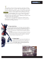
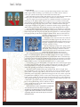
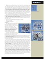
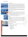
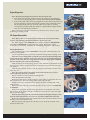
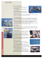
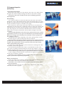
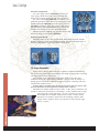
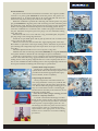
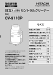
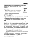
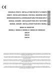
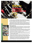
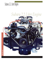
Subaru 2.2 Liter Engine
The
End Wrench
Subaru 2.2 Liter Engine
4
T
his edition of The End Wrench introduces the Subaru 2.2 liter
naturally aspirated (N/A) and 2.2 liter turbocharged horizontally
opposed overhead cam (OHC) engines. It reviews the mechanical
features of these engines and the differences between
Introduction
existing engines. It also covers the procedures used in
diagnosing and overhauling these engines. A list of applicable
Important Notes and Cautions, Service Bulletins and Special Tools
is included at the end of this article.
Always refer to the appropriate model year Subaru Service
Manual and the applicable service bulletins for all specification
and detailed servicing procedures.
2.2L Engine Identification
The 2.2L engine designation is the sixth digit of the vehicle identification number (VIN). It is important to always first identify the engine before
beginning diagnosis and servicing. Body type and transmission type, as
well as the model year, are also information pertinent to engine diagnosis
and servicing. This information is available from the VIN and the appropriate
service manual.
The engine serial number is located on the machined boss on the left
side of the clutch housing. The 2.2L engine designation is EJ22. Piston
and bearing dimension information is stamped on a machined
surface where the crankcase halves meet.
2.2L Engine Features
The 2.2L SOHC four valves per cylinder engine is an
addition to the existing Subaru “Boxer” design. The horizontally opposed, four stroke, four cylinder, liquid
cooled, gasoline engine has aluminum alloy block and
heads. It uses a normally aspirated or turbocharged MPI system.
The cylinder liners are of a cast iron dry type design.
Piston And Bearing Information
5
Subaru 2. 2 Liter Engine
Cross Flow Cylinder Head
The
End Wrench
Camshafts
Cylinder Heads
The 2.2L engine uses a crossflow cylinder head design similar to the 1800cc
OHC engine. Better breathing is provided by the two intake and two exhaust
valves per cylinder which improves the intake and exhaust flow.
Fine-tuned high velocity intake and exhaust ports are used. The dual intake and
exhaust ports are siamesed to further improve intake and exhaust flow.
The 2.2L engine uses a compact pentroof combustion chamber versus the bathtub design of the 1800cc/2700cc Subaru engines. It has a centrally located spark
plug which provides the quickest, most efficient combustion with a uniform flame
front from the plug to the top of the piston. This, combined with the 30 degree
valve angle compliments the pentroof combustion chamber shape optimizing low
and medium speed torque. The cylinder heads are interchangeable left to right.
The 2.2L turbocharged engine cylinder heads have been modified to withstand
increased internal combustion pressures. The coolant passages have been changed to
match the closed deck design of the crankcase. These heads are not interchangeable
from side to side nor with the N/A engine cylinder heads. There are three holes in
the right cylinder head for the turbo oil supply, oil
return, and coolant return.
The intake valves and seats have been reduced
to 27mm for the turbo engine only. The valve seat
material for both the intake and the exhaust valves
has been changed to increase hardness to provide
a greater resistance to wear.
The valve train uses a single valve spring system
versus the dual spring system of the 1800cc engine.
The intake valves are larger than the exhaust
valves. The valve seal color determines location:
Rocker Shaft Assembly
intake seals are black, exhaust seals are brown.
The camshaft bearing journals are located in the cylinder head. This design
improves camshaft support. The left camshaft is longer than the right camshaft to
properly align the cam belt sprockets due to cylinder head offset. A camshaft support bolts to the front of the left cylinder head to support the camshaft. A retaining
plate, with oil seal, is attached to the rear of the left cylinder head. The rear of the
right cylinder head has a cover plate which also serves as a thrust plate.
A camshaft support has been added to the right side of the turbocharged engine
to supply oil to the turbo and return coolant from the turbo. Oil and water separation is provided by an o-ring. The camshaft has a different profile designed to
match the operating characteristics of the turbo engine.
The rocker shaft assembly bolts to the cylinder head. There are eight bolts
through the three cast iron supports. The intake valves have individual rocker
arms, while a siamese rocker arm is used for each two exhaust valves. The all
aluminum rocker arms have a sintered metal slipper as the cam contact. A pressed
lead aluminum bushing is used for each rocker arm bearing surface. The position
of the spring washers on the steel rocker shaft provide proper rocker alignment
and spacing. These spring washers must be returned to their original position. The
rocker shaft is part of the oiling system providing oil
flow to the rocker bearing surfaces and HLAs. Relief
valves at both ends of the rocker shafts maintain stable oil pressure to the HLAs.
Note: The roller rocker cam follower system that
was introduced on the 1.8L Impreza engines, is
installed on all 1995 model year and later 2.2 liter
engines. The roller assemblies are not serviceable
separately, but the rocker arms may be serviced as
individual units.
Roller Rocker Cam Followers
6
The HLAs used in the 2.2L engine are very small in size. Compare them to the
size of the 1800cc and 2700cc HLAs. One advantage of these HLAs is the reduction
of reciprocating weight. The HLAs are installed in the rocker arms while the
1800cc /2700cc HLAs are installed in the cylinder head. The HLAs directly contact
the valve stem instead of contacting the rocker arm as in the 1800cc/2700cc engines.
The head gaskets are carbon composition with a metal hooked core. O-rings
are used to seal the oil passages. The entire gasket surface is silicone coated to
Hydraulic Lash Adjusters (HLAs)
improve sealing characteristics during initial installation. This also eliminates the
need for re-torquing the cylinder head bolts after the engine has been operated.
The N/A cylinder head gaskets are interchangeable from side to side.
The turbo engine cylinder head gaskets have been modified to match the closed
deck design of the turbo crankcase. The gaskets are not interchangeable from side
to side or with the gaskets from the N/A engine.
The water ports have been repositioned to match the passages in the heads
and crankcase. The grommet area around the cylinder has been increased for
improved sealing.
The gaskets can be identified by the number of notches:
• N/A: two notches
• TURBO: three notches
Crankcase
The crankcase has five main bearings
which provide high case rigidity and
improved crank support which increases
engine life and performance. The
crankcase uses an open deck casting
design for the cylinder liners. The Turbo
engine uses a closed deck design. In
Crankcase
addition, the flywheel housing is cast
with the crankcase which adds to
increased rigidity and strength.
Oil jets have been added to the lower
Crankshaft
portion of the turbo crankcase in order to
lubricate and cool the pistons. The jets
are not operative at lower RPM because they are pressure controlled to open at 57
psi. The jets can be cleaned.
The balanced forged crankshaft has fillet rolled micro-polished journals for
increased strength and reduced friction. Due to the “Boxer” design, a counterbalance shaft is not required.
Due to increased material used to strengthen the large end of the rod, the rod
bolts are pressed into the rod. In comparison, the 1800cc rod bolts are pressed into Pistons
the bearing cap. An oiling notch is located on the large end of the rod below the
FUJI symbol. This provides oil flow to the piston pin and the cylinder walls. The
rods are not drilled.
The 2.2L pistons are cast aluminum alloy and feature a 2mm offset piston pin.
The pistons are directional for the left and the right side of the engine and are
stamped with an “L” or “R”. In addition, each piston is stamped with an arrow
which must point to front of the engine. The valve reliefs for the intake and
exhaust valves are different sizes to prevent valve contact with the piston should
the cam belt break. The pistons use three rings, two compression and one oil.
The 1st and 2nd ring land groove thickness has been increased to provide
additional strength due to the increased combustion pressures of the turbo engine.
The piston ring’s width and depth have also been increased to improve the cooling
efficiency of the top of the piston. In addition, the top of the ring is coated with
molybdenum to prevent metal disposition with the piston. The material itself has
been changed to hard chrome for increased resistance to wear.
7
Subaru 2. 2 Liter Engine
Timing Belt
Cam Belt Tensioner
Water Pump
Timing Belt System
A single belt is used to drive both camshafts and the water pump. This provides
more precise valve timing. The cam belt width is 30mm (1.18 inches) to increase
cam belt life. The belt is constructed of wear resistant double canvas and heat
resistant rubber materials with a wire core. A round tooth profile is used for quieter
operation. The belt has an automatic cam belt tensioner which allows for thermal
expansion and contraction. The cam belt path is from the crankshaft sprocket to the
tensioner, to the left camshaft sprocket, to the water pump pulley, to the lower left
idler to the lower right idler, to the right camshaft sprocket, to the upper right idler
and back to the crankshaft sprocket.
The cam belt covers and dust seals are resin molded and protect the timing belt
from dust and water. There are additional dust seals on the left and right inner covers. These seals increase protection of the cam belt from dust and water and also
improve cam belt noise isolation.
Cooling System
The water pump pulley is driven by the back side of the timing belt. The pump
is mounted to the lower front of the engine. The thermostat is located in the lower
part of the pump housing. This location provides even engine warm-up by improved
metering of the coolant temperature. The thermostat senses the temperature of the
crankcase and radiator coolant as it is mixed.
Because the thermostat housing is located on the lower front of the engine,
all of the coolant must be drained to change the thermostat.
The heater core also serves as the by-pass system.
Oil Pump
The trichoid gear type oil pump is driven directly by the crankshaft. The pump
is bolted to the front of the engine for serviceability. The relief valve located in the
2
pump regulates oil pressure to 71 psi (5 kg-cm ). The filter by-pass valve is located
in the oil filter.
The oil pump has a reservoir which maintains oil for rotor lubrication. This is
especially helpful when the engine has not been operated for extended periods of
time. The reservoir also provides emergency oiling for the pump if there is a temporary loss of oil supply.
2.2L Engine Servicing & Diagnostics
The
End Wrench
Oil Pump
In Vehicle Servicing
The following services may be completed without removal of the engine from
the vehicle.
• Removal/replacement of cam belt
• Water pump removal/replacement
• Oil pump servicing
• Intake manifold
• Rocker covers
• Rocker arm assemblies
• Cylinder head removal
• Camshafts
• Turbocharger
8
Engine Diagnostics
Note: The following diagnostics pertain to the 2.2L engine only.
• Valve train noise (clacking sound). Operate the engine for approximately
one hour before diagnosing HLAs as the problem. Do not rev the engine!
• If the rocker shaft relief valves are plugged, the rocker shaft oil pressure will
increase during low engine temperature operation. This could result in the
HLAs being forced part way out of the rocker arm sockets. A clacking
sound may be produced which is similar to collapsed HLAs. Engine misfire
may also occur during this condition.
If the relief valves will not hold pressure, the HLAs may collapse, again
producing a clacking sound.
Removing Crank Pulley
2.2L Engine Disassembly
Note: Refer to the service manual for the detailed step-by-step disassembly
sequence. The following information addresses special steps only.
The 1800cc engine stands 499817000 can be used with adapter RH 498457000
and adapter LH 498457100 to support the 2.2L engine. Remove the engine
accessories: i.e. drive belts, alternator, air conditioning compressor, and brackets.
Timing Belt Removal
Use crankshaft pulley wrench 499977000 to remove the crankshaft pulley bolt,
then remove the pulley.
Use the crankshaft pulley to rotate the crankshaft to align the belt timing marks.
Note: There are two timing marks on both the cam pulleys and the crankshaft pulley,
a notch and an arrow. Align the notch on the outer rim of each camshaft pulley with
the notch on the inner cam cases. Align the notch on the rear flange of the crankshaft
sprocket with the notch on the oil pump housing.
Mark the belt at the three timing notches. This will make reinstallation much
easier and also insures proper placement of the belt between the left and right
cam pulleys.
Mark the belt rotation direction, The belt must be reinstalled to rotate in the
same direction.
Note: New belts will have the timing marks printed on the belt as well as
arrows indicating direction of rotation.
First, loosen the cam belt tensioner mounting bolts.
Note: Do not remove the bolts.
Remove the idler pulleys in this sequence: lower right (1-3 side), then the lower
left (2-4 side, next to the water pump). Then remove the cam belt.
Finally, remove the cam belt tensioner pulley, tensioner assembly, and crankshaft sprocket.
Remove the left and right camshaft sprockets using cam wrench 499207100
or 49940700.
Notice the locating pin on back of the sprockets for reinstallation. Also locate
the reluctors on the back of the left camshaft sprocket. These are the cam angle
sensor reference triggers.
Note: The left camshaft sprocket must not be installed on the right camshaft, as damage to the inner right cam belt cover may occur. A no start condition also will result.
Remove the mounting bolts and carefully remove the tensioner bracket to avoid
damage to the friction-fit dust seals.
Remove the left and right inner cam belt covers. Note the location of the
friction-fit dust seals.
Marking Timing Belt
Removing Idler Pulleys
Camshaft Sprocket
Inner Cam Belt Covers
9
Subaru 2. 2 Liter Engine
Engine Accessory Removal
Remove the hoses, electrical connections,
sensors, switches, intake manifold, and intake
manifold gaskets.
Note: The rubber coated metal gaskets are
one-time use only.
Remove dipstick tube and then remove the
water pump and rubber coated metal gasket.
The gasket is one-time use only. Retain the dust
Intake Manifold
seals for later reassembly.
Remove the oil pump. Observe the condition and location of the o-ring seal and
the dust seals. Retain the dust seals for later reassembly.
Cylinder Head Removal
Loosen all head bolts in the reverse order of the tightening sequence, and then
remove all of the cylinder head bolts except #1. Lightly tap the cylinder head with a
rubber mallet to loosen the head from the gasket. Then remove #1 bolt and the cylinder head with the head gasket. Repeat the above steps for the other cylinder head.
Note: The head gaskets are carbon composition with integrated o-rings. The
gaskets are interchangeable from left to right on N/A engines only.
Note: It is not necessary to remove the valve cover while removing the cylinder
head unless servicing of the valve components is required.
Removing Cylinder Head
Piston Pin Removal
Use piston pin remover 499097300 or 499097500
to remove the piston pin. Insert the tool 3/4 of the
way into the pin and pull the tool with the pin
through the access hole. Repeat for the remaining
pistons. Finally, rotate the crankshaft to position the
pistons at the top of the cylinders. Repeat the procedure for the other cylinders.
Note: Use caution while rotating the crankshaft
to prevent the connecting rod large ends from damaging the lower cylinder bores.
Hidden Crankcase Bolts
To split the crankcase remove all 16 of the
crankcase bolts. Six of the bolts are hidden in the
water passages, four in the RH case (1-3 side) and
two in the LH case (2-4 side).
Note: All six of the hidden shouldered crankcase
bolts have sealing washers. These bolts are not interchangeable with the other crankcase bolts. The sealing
washers are one-time use ONLY.
Carefully separate the crankcase halves.
Note: Identify the location of the four O-rings
(three small, one large), in the mating surface of the
right (1-3 side ) crankcase. The black o-rings are for oil
passages, the orange o-ring is for a coolant passage.
Removing Wrist Pin
Hidden Crankcase Bolts And
Sealing Washers
Crankcase O-Ring Seals
The
End Wrench
Removing Oil Pan
Oil Pan Removal
Remove the oil pan bolts. Use a thin gasket scraper/putty knife and a rubber
mallet to loosen the oil pan. Remove the oil pan. Notice the location of the oil seal
for the drain tube. Remove the oil pick-up tube and also note the o-ring. Remove
the oil pan baffle plate (windage tray).
10
2.2L Component Inspection
and Servicing
Cylinder Head Disassembly
Remove the valve rocker cover bolts and the valve rocker cover. Then remove
the eight rocker shaft assembly retaining bolts and the rocker shaft assembly.
Note: Remove the rocker assembly slowly to prevent binding against the
mounting dowels.
HLA Handling
Use a small screwdriver to remove the HLA from the rocker socket. Do not
damage the o-rings of the machined surfaces when removing the HLAs. To check
the HLAs for proper operation, squeeze the HLA between your thumb and finger.
The HLA should not compress, it should not be spongy.
Place an HLA in a clean 12 mm socket. The socket serves as an oil reservoir.
Add engine oil to the socket. Use a small allen wrench or paper clip to depress the
check ball. Depress and release the HLA plunger while you hold the check ball
open. This purges the air from the HLA and fills the HLA with oil. It usually
requires only one stroke to fill the HLA. Store the HLAs in engine oil for later
reassembly.
Note: Partially filled HLAs will result in noisy operation of the valve train for
approximately one hour. To test, squeeze the HLA between your thumb and finger.
If the HLA is spongy, repeat the fill process. If the HLA can not be pumped to a
firm condition, replace it.
Assemble the rocker shaft components, rocker arms, spring washers, and the
rocker shaft supports. Lubricate shaft and rocker arms with oil.
Note: The rockers and supports should be returned to their original position on
the shaft. The cut out portion of the rocker shaft must face the oil hole in the rocker support. The spring washers must be properly located on the shaft. Always
replace any deformed spring washers.
Lock the rocker shaft in the proper position with the two retaining bolts. Then
fill the HLA sockets with engine oil.
Press the HLAs (by hand) into the rockers to install the HLAs in the rocker
arms. Some oil will drain from the bleed hole. Press the HLA until the o-ring seats.
Install the remaining HLAs. Be sure to check for spongy HLAs during installation.
Note: The HLA O-rings should always be replaced when the HLAs are reinstalled.
Look for leakage from the tensioner rod and seal area. Slight traces of oil at rod
oil seal does not indicate a problem.
Note: Refer to Service Manual Section 2-3 (W2B2) “Inspection of belt tension
adjuster” for tensioner compression specifications.
Rocker Arm Inspection
Inspect the rocker arms for damage. Also inspect the rocker arm bearing surface
for wear. Replace the rocker arm if bearing wear is excessive.
Note: Refer to Service Manual Section 2-3 (W3C2), Inspection of Valve Rocker
Arm for specifications.
Finally, inspect the rocker arm cam contact surface. Replace the rocker arm(s)
when they are scored or gouged.
11
Removing HLA
Filling And Bleeding HLA
Installing HLA
Subaru 2. 2 Liter Engine
Valvetrain Components
Use valve spring remover 499718000 to remove the
valve springs. Then remove the valves and seals. The
intake seals are black and the exhaust seals are brown.
Use valve seal installer 498857100, to install the valve
guide seals (black for intake, brown for exhaust). Then use
cylinder head table 498267200 and valve spring remover
499718000 to install the valve spring and retainer. Install
the camshaft into the cylinder head bearing journals. Be
careful to not damage or score the camshaft journals.
Install the left rear camshaft plug (oil seal). Then install
the oil seal using oil seal installer 499587100.
Inspecting Rocker Arms
Storing Cylinder Heads
Install the rocker cover to the cylinder head. Temporarily store the cylinder
head by standing it on the exhaust manifold studs. This prevents bleed down of
the HLAs. Repeat these steps for the other cylinder head.
Cylinder Head Storage Position
2.2L Engine Reassembly
Assembling Crankcase
The
End Wrench
Always refer to Service Manual Section 2-3 (W6C5 to W6D2) for the bearing
size, oil clearance, and torque specifications. The “FUJI” symbol on the connecting
rods must face the front of the engine.
Apply sealant to the crankcase mating surface on the o-ring side of the
crankcase. Do not allow the sealant to enter the o-ring grooves, oil passages, or
bearing grooves. Install the crankshaft assembly. Align the connecting rods, and
assemble the crankcase halves.
Caution: Remove all fluids from the threaded portions of the case halves. This
prevents hydrostatic lock and potential cracking of the crankcase.
Install the four hidden crankcase bolts on the 1 - 3 side. Always install new seal
washers to these bolts. Install the two remaining 1 - 3 side crankcase bolts. Torque
the 6 large bolts on the right side (1 - 3) to 4 to 22 ft lbs (2 to 3 Kg-m).
Next install the two hidden crankcase bolts on the 2- 4 side. Always
install new seal washers. Install all of the remaining crankcase bolts.
Torque all the crankcase bolts to specifications. Start with the right
side (1 - 3) bolts.
12
Piston Installation
The pistons are directional and must be returned to the original cylinder
locations. Use piston guide 498747100 to install the pistons. The pistons are
marked with an “L” for the left side and an “R” for the right side. The arrow on
the head of each piston must point to the front of the engine.
Rotate the crankshaft to position the connecting rod with the piston. Use piston
pin guide 499017100 to align the piston and connecting rod. Then install the piston
pin. Install the circlip. Note the proper direction of the circlip on early production
models. The tang must be tilted out. Repeat for the remaining pistons. Slowly
rotate the crankshaft two revolutions. This confirms the proper installation of
Installing Pistons
the pins. Install the front piston pin access plugs. Use new aluminum sealing
rings and sealer.
Install the left side access cover and new o-ring, PCV baffle plate, and piston
pin plug using a new sealing ring and sealer.
Install the oil pan baffle plate and oil pick-up tube. Be sure to install a new
o-ring to the oil pick-up tube.
Install a new oil seal on the oil return tube. Apply liquid gasket sealer FUJI
Bond 1207C or equivalent to the oil pan mating surface. Install the oil pan and oil
pan retaining bolts. Diagonally torque the oil pan bolts on one pass to 0.5 Kg-m
(3.6 ft lbs).
Install the dipstick tube. Be sure to use two (2) new o-ring seals.
Install the rear main oil seal using seal installer (499587200), oil seal guide (499597100)
Piston Pin Guide
and a plastic hammer. Lubricate the seal with engine oil prior to installation.
Install the oil pump. Refer to service manual section 2-4([W1D0) for proper
location of the sealer and o-ring. Apply FUJI Bond 1215 sealer or equivalent to the
mating surface of the oil pump. Align the flats two on the oil pump with the two
flats on the crankshaft and the mounting holes in the oil pump flange with the two
dowel pins. Install the mounting bolts and torque to specifications.
Cylinder Head Torque Sequence
Install a new cylinder head gasket (dry) and the
cylinder head. Follow the bolt torque sequence and
procedures listed in the appropriate MY Legacy
Installing Rear Main Seal
Service Manual, Section 2-3 (W5E1).
Compressing the Tensioner
Slowly compress the cam belt tensioner in a
vise, using aluminum or brass jaws, until the hole
in the piston aligns with the hole in the tensioner
case. Install a tensioner plunger retaining pin. You
may use a small allen wrench as a retaining pin.
Torquing Cylinder Head Bolts Install tensioner assembly to the crankcase, do not
tighten the mounting bolts.
Note: Do not remove plunger retaining pin until
cam belt is completely installed.
Installing Oil Pump
A revised cam belt tensioner design was introduced on later 2.2 liter engines. The revised tensioner requires a special service procedure to retract the
tension piston. Compressing the piston in a vise
Compressing Belt Tensioner Piston
will damage the tensioner piston and it will not
extend properly when it is reinstalled on the
engine. Refer to the appropriate section in the
Subaru service manual for tensioner handling
procedures.
Revised Belt Tensioner Procedure
13
Subaru 2. 2 Liter Engine
Reinstalling Camshaft Sprockets
Loading Tensioner Idler
Cam Belt Installation
Install the camshaft sprockets using camshaft sprocket wrench 499207100 or
499407000. Refer to the service manual for the proper specifications. The left
sprocket has the cam angle reluctors and is not interchangeable with the right
sprocket. Damage to the dust cover will result from improper installation.
Install the cam belt idler pulleys except the lower right (1 - 3 side) and the lower
left (2 - 4). Install the crankshaft sprocket and align the crankshaft sprocket and
camshaft sprockets with the belt timing notches (12 o’clock). Do not rotate
camshafts more than necessary as the HLAs will bleed down.
Install the cam belt in the following sequence:
❶ Begin at the crankshaft sprocket
- Align the mark on the cam belt with the crankshaft sprocket notch.
❷ Place the belt under the cam belt tensioner and over the left cam sprocket.
- Align the mark on cam belt with the camshaft sprocket notch.
❸ Place the belt under the upper right idler pulley and over the right
cam sprocket.
- Align the mark on the cam belt with camshaft sprocket notch.
❹ Place the belt over the water pump pulley.
❺ Install the lower left and right idler pulleys.
Use a screwdriver to load the tensioner idler. Push the idler toward the crankshaft sprocket. Tighten the tensioner mounting bolts to specified torque.
Carefully remove the tensioner plunger retaining pin. This automatically sets
the cam belt tension. Slowly rock the crankshaft left to right to left to distribute the
cam belt tension to the belt.
Note: Do not rotate the crankshaft unnecessarily as the HLAs may bleed down.
Verify that the cam timing is correct by checking the cam belt alignment. The
crankshaft sprocket notch and mark should be aligned. Check to be sure that the
notches of the camshafts sprockets and the belt marks are properly aligned.
Install the outer cam belt covers. Be sure to install the shouldered bolts in the
center cover. Check the position and fit of the dust seals.
Install the pulley using crank pulley wrench 499977000. Install the engine
accessories and drive belts. Note the new style belt tension adjusters. Fill the
engine with oil.
The
End Wrench
Checking Cam Belt Alignment
14
2.2 Liter Engine Enhancements
Beginning in the 1997 Model Year, the 2.2 liter engine for 1997 Legacy and
Impreza models has had internal and external changes that yield an approximately
10% increase in power and 3% increase in fuel economy. Accomplishing this
involves many factors, one of which is engine friction reduction.
The piston, a major source of engine friction, has been coated with a friction
reducing agent called Molybenum. This thin coating not only allows smoother
travel through the cylinder, but also reduces cylinder wall scuffing.
The skirt of the piston has been reshaped and the overall weight has been
reduced by approximately 100 grams. Compression ratio has been increased to
9.7 to 1 by reshaping the crown of the piston. This eliminates the clearance that
was available between the piston at TDC and the fully opened valve. Piston pin
offset has been changed to 0.5 mm. Piston to cylinder wall clearance has been
reduced by increasing the piston diameter.
Another source of high engine friction is the valve train. Hydraulic lash
adjusters (HLAs) are always in contact with the valves. The hydraulic pressure of
the lash adjuster must be overcome during operation and during the most critical
time of engine start. To overcome this situation and to contribute to the total reduction of friction loss, 1997 and later SOHC engines have solid valve adjusters. The
scheduled service of this valve train is set at 100,000 miles. SOHC engines now use
an adjustment screw to adjust valve clearance.
Tools required for 2.2 valve adjustment include a thickness gauge, 10mm
wrench, stubby standard screwdriver, and crankshaft wrench.
Follow the instructions below for set up and adjustment.
• Remove the right bank camshaft belt outer cover.
• Rotate the engine until the arrow on the camshaft sprocket is at 12 o’clock.
Remember that the camshaft sprocket has an arrow and a mark for the timing belt
timing. Make certain that the arrow is used for valve adjustments, not the mark.
Standard valve clearance:
Intake valves 0.20 ± 0.02 mm
Exhaust valves 0.25 ± 0.02 mm
• Using a standard thickness gauge to measure the clearance of the intake
and exhaust valves in cylinder 1 only. Adjust the clearance by loosening
the locknut and turning the adjustment screw until the proper clearance
is obtained.
• Rotate the engine until the arrow on the camshaft sprocket is at 3 o’clock.
Check and adjust the clearance of the intake and exhaust valves on
cylinder 3 only.
• Rotate the engine until the arrow on the camshaft sprocket is at 6 o’clock.
Check and adjust the clearance of the intake and exhaust valves on
cylinder 2 only.
• Rotate the engine until the arrow on camshaft sprocket is at 9 o’clock. Check
and adjust the clearance of the intake and exhaust valves on cylinder 4 only.
Solid Valve Adjusters
15
Subaru 2. 2 Liter Engine
Notes and Cautions
Tensioner Bolt Caution
Tightening Camshaft Sprocket Bolts
Crankcase Bolt Holes
Cylinder Head Torque Sequence
2.2L Engine Reassembly
• The rockers and supports should be returned to their original positions on
the shaft. The cut out portion of the rocker shaft must face the oil hole in the
rocker support. The spring washers must be properly located on the shaft.
Always replace any deformed spring washers.
• The HLA o-rings should always be replaced when the HLAs are reinstalled.
• Install the rocker assembly carefully to prevent binding against the
mounting dowels.
• Remove all fluids from the threaded portions of the case halves. This
prevents hydrostatic lock and potential cracking of the crankcase.
• Carefully follow the cylinder head torque sequence. Remember that the
re-tightening angle must not exceed 180 degrees. Proper use of the torque
procedure eliminates the need to retorque the cylinder head bolts after
running the engine. Refer to Service Manual Section 2-3 (W5E1).
• The left camshaft sprocket must not be installed on the right camshaft, as
damage to the inner right cam belt cover will result.
• Do not remove the plunger retaining pin from the cam belt tensioner until
the cam belt is completely installed.
• Do not rotate the crankshaft unnecessarily as the HLAs may bleed down.
The
End Wrench
Cam Belt Tensioner Retaining Pin
2.2L Engine Disassembly
• There are two timing marks on both the cam pulleys and the crankshaft
pulley, a notch and an arrow. Align the notch on the outer rim of each
camshaft pulley with the notch on the inner cam cases. Align the notch on the
rear flange of the crankshaft sprocket with the notch on the oil pump housing.
• New belts will have the timing marks printed on the belt as well as
arrows indicating rotation direction.
• During the cam belt removal procedure, initially loosen, but do not remove,
the cam belt tensioner bolts until the belt and idler pulleys have been removed.
• The 1800cc cam wrench must be modified to fit the 2.2L camshaft sprocket.
Tool 499207100 is the preferred tool.
• The rubber coated metal intake manifold gaskets are one-time use only.
Discard and replace with a new set.
• The carbon composition head gaskets with integrated o-rings are inter
changeable from left to right on 1990 to 1994 N/A engines only.
• It is not necessary to remove the valve cover while removing the cylinder
head unless servicing of the valve components is required.
• Use caution while rotating the crankshaft to prevent the connecting rod
large ends from damaging the lower cylinder bores.
• All six (6) of the hidden shouldered crankcase bolts have sealing washers.
These bolts are not interchangeable with the other crankcase bolts. The
sealing washers are one-time use ONLY.
• Identify the location of the four o-rings (three small, one large), in the
mating surface of the right (1-3) side crankcase. The black o-rings are for oil
passages, the orange o-ring is for coolant passage.
• Remove the rocker assembly slowly to prevent binding against the
mounting dowels.
Partially filled HLAs will result in noisy operation of the valve train for approximately one hour. To test, squeeze the HLA between your thumb and finger. If the
HLA is spongy, repeat the fill process. If the HLA can not be pumped to a firm
condition, replace it.
16
Subaru .2. 2 Liter Engine
General Hand Tools & Supplies
The
End Wrench
Service Bulletins
No.
01-106-88
Date
2/1/88
02-44-86
2/4/86
02-48-86
7/2/86
02-49-86
10/9/86
02-50-86
11/7/86
02-56-87
10/26/87
02-64-88
6/14/88
02-67-88
12/22/88
02-68-89
5/17/89
02-69-89
7/11/89
02-71-89
10/18/89
02-74-90
02-75-90
4/9/90
9/11/90
02-76-91
4/2/91
02-77-90
12/28/90
02-78-91
02-79-91
1/24/91
3/29/91
02-80-91
02-81-91
5/9/91
8/15/91
02-83-91
9/17/91
02-84-91
11/12/91
02-85-91
12/19/91
02-88-93
2/5/93
02-90-94
02-90-94R
10-48-87
12/2/94
12/2/94
11/30/87
Title
Recommended
Sealants and
Adhesives
OHC Replacement
Valve Guide Seals
Valve Guide Seals
Remarks
Instructions for
servicing valve
guide seals with
the engine in the
vehicle and using
tool kit part
number
X9971AA100
Valve Stem Height
Measurement
Turbocharger
Diagnosis
Turbo Engine
Knocking Noise
All Subaru EnginesIntake Manifold
Gasket Information
Proper Procedure For
LH Timing Belt
Tension - 1.8L
Legacy HLA Noise Rocker Shaft
Cleaning Procedure
Legacy Engine Oil Level
Checking
Maintenance
Reminder
Engine Oil Pan Removal
Bleeding Air From Legacy
Cooling System
Radiator
Replacement
Procedures
Legacy Cylinder Head R&R
In-Vehicle Procedure
Cam Belt Timing Tips
Legacy Engine Block Mod A/C
Compressor Mounting Bolt Change
Legacy Engine Oil Level Gauge
2.2L Cylinder Head Resurfacing
(Grinding) Specs 1991 Legacy
Service Manual Correction
Engine Oil Seepage at Cylinder Head
or Acc. Mounting Bolt
Diagnostic Aids for Driveability
Complaints
Revised Cylinder
Head Bolt Torque
Procedures
Cylinder Head
Crack Between
Valve Seats
Engine Oil Pump Leaks
Engine Oil Pump Leaks
Cooling System Cleansing
18
General hand tools and supplies
Dial indicator
Dye penetrant
Feeler gauge
Micrometers
Plastigauge
Press
Rubber or Plastic Hammer
Fuji Bond 1105 or equivalent
Fuji Bond 1107C or equivalent
Fuji Bond 1215 or equivalent
Torque wrench (ft-lb) and (in. lb.)
Vernier calipers
Reference Materials
Subaru Service Manuals
Technician Reference Booklets
Special tools
399094310
479587300
498037100
498267200
498457000
498457100
498747100
498857100
499017100
499037100
499097500
499207100
499587100
499587200
499597000
499718000
499718400
499767000
499767200
499767400
499817000
499977000
898968600
499597100
499987500
Piston pin remover (1800cc tool)
Oil seal installer
Camshaft journal plug installer
Cylinder head table
Engine stand adapter RH
Engine stand adapter LH
Piston guide
Valve oil seal guide
Piston pin guide
Connecting rod bushing
remover & installer
Piston pin remover
Camshaft sprocket wrench
Camshaft oil seal installer
Crankshaft oil seal installer
Camshaft oil seal guide
Valve spring remover
Valve spring compressor adapter
Valve guide adjuster
Valve guide remover
Valve guide reamer
Engine stands (2)
Crank pulley wrench
Circlip pliers (or SNAP-ON long
nose pliers 911CP)
Crankshaft oil seal guide
Crankshaft socket
Note: Yearly Subaru Service Bulletin Publications are available
for purchase by calling Helm Incorporated at 1-800-782-4356.
You may also FAX your request to 1-313-865-5927, between
the hours of 8:00am - 6:00pm EST, Monday through Friday.
Helm accepts Mastercard, Visa, Discover, checks, and money orders.
Overnight or Second Day shipping is available at additional cost.