1
AUTOMATIC PRODUCTS international, ltd.
R
SERVICE MANUAL
OPERATING MANUAL
PARTS MANUAL
PLEASE DO NOT
REMOVE MANUAL
FROM MACHINE.
75 West Plato Boulevard ● St. Paul, Minnesota 55107-2095
APi 748 V1.1 406
1.1
P/N 77500001
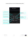
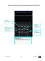
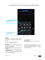
Fast Track Links
Description
Service Modes
Troubleshooting
Maintenance
Parts Drawings
APi 748 V1.1 406
1.2
P/N 77500001
Section 1
Warranty
How to use manual
Installation
1.1
1.2
1.3 – 1.4
Section 2 - Description
Introduction
Major Components
Operation
Programmable Options
2.1 – 2.3
2.4 – 2.5
2.6 – 2.7
2.7 – 2.10
Section 3 – Service Mode
Introduction
Service Mode Map
Accessing Service Modes
Coin Mech Inventory
Options
Price – Shelves
History
Cash System Type
Set Up
Audit Data
Security Code
Diagnostics
3.1
3.2
3.3
3.4 – 3.5
3.6 – 3.8
3.9 – 3.11
3.12 – 3.15
3.16 – 3.21
3.22 – 3.25
3.26
3.27 – 3.28
3.29 – 3.33
Section 4 – Troubleshooting
Introduction
Control Systems
Boards
Serial Communications
Indicator LEDS
Printer Set Up
Error Messages
History Log
Turret Motor Errors
Power-Up Initialization
Refrigeration
Error Messages
History Events
Troubleshooting Charts
4.1
4.1 – 4.3
4.1
4.1
4.2 – 4.3
4.4
4.4
4.4
4.5
4.5
4.6 – 4.9
4.10 – 4.11
4.12
4.13 – 4.17
Section 5 – Maintenance
Introduction
Delivery Door Operation
Checking Refrigeration System
Turret Removal
Delivery Door Removal
Cleaning
5.1
5.1
5.1
5.2
5.2
5.3
Section 6 – Parts
Parts Drawings
APi 748 V1.1 406
6.1 -6.36
1.3
P/N 77500001
WARRANTY
Automatic Products international ltd. (APi) expressly warrants these automatic merchandisers (the "Unit"),
manufactured by it, to be free under normal use and service from defects in material or workmanship for a
period of two (2) years from the date of delivery of this Unit to the original purchaser. This warranty extends
only to the original purchaser of the Unit. The exclusive remedy for this warranty is limited to the repair or
replacement, at APi's sole option, of any part or parts of the Unit that are returned to APi or to the authorized
dealer or distributor of APi from whom the unit was purchased with all transportation charges prepaid, and
which, on APi's examination, shall, conclusively appear to have been defective. This warranty does not:
a. extend to any Unit, or part thereof, that was subjected to misuse, neglect, or accident by other than APi
after its delivery to the original purchaser;
b. extend to any Unit, or part thereof, that was modified, altered, incorrectly wired or improperly installed by
anyone other than APi or used in violation of the instructions provided by APi;
c.
extend to a Unit which has been repaired or altered by anyone other than APi or authorized dealer/
distributor;
d. extend to a Unit which has had the serial number removed, defaced or otherwise altered;
e. extend to plastic or glass windows, lamps, fluorescent tubes and water contact parts;
f.
extend to any unit used outdoors
g. extend to accessories used with the Unit that were manufactured by some person or entity other than
APi.
APi DISCLAIMS ALL OTHER WARRANTIES OF ANY KIND AS TO THE UNIT AND ALL WARRANTIES
OF ANY KIND AS TO ANY ACCESSORIES. THIS DISCLAIMER OF WARRANTIES INCLUDES ANY
EXPRESS WARRANTIES OTHER THAN THE LIMITED WARRANTY PROVIDED ABOVE AS TO THE
UNIT AND ALL IMPLIED WARRANTIES OF MERCHANTABILITY AND FITNESS FOR A PARTICULAR
PURPOSE AS TO THE UNIT AND ANY ACCESSORIES. UNDER NO CIRCUMSTANCES SHALL APi BE
RESPONSIBLE FOR ANY INCIDENTAL, CONSEQUENTIAL OR SPECIAL DAMAGES, LOSSES OR
EXPENSES ARISING FROM OR IN CONNECTION WITH THE USE OF, OR THE INABILITY TO USE, THE
GOODS FOR ANY PURPOSE WHATSOEVER. No representative of APi or any other person is authorized
to assume for APi, or agree to on the behalf of APi, any other liability or warranty in connection with the sale
of this Unit.
APi reserves the right to make any changes or improvements in its products without notice and without
obligation, and without being required to make corresponding changes or improvements in Unit theretofore
manufactured or sold.
Should you have any questions pertaining to this manual or the vendor, please contact your APi distributor or
write directly to:
Technical Services Dept.
Automatic Products int’l
75 W. Plato Blvd
St Paul Minnesota 55107 USA
© 2003 Automatic Products international, ltd
APi 748 V1.1 406
1.1
P/N 77500001
Back
This manual provides detailed information regarding the unpacking, setup, installation, and programming and
operation of the Automatic Products international 748 Showcase cold food merchandiser. Please read and
understand the contents of this manual before attempting to setup and install the machine.
HOW TO USE THIS MANUAL
This manual is divided into four basic parts:
1.
Unpacking and installation.
2.
Components.
3.
Optional Equipment
4.
Quick Set up Guide.
5.
Troubleshooting.
CAUTION: This machine is designed for indoor usage only. Any
other usage may void the Manufacturers Warranty.
CAUTION: Certain procedures in both the operating section and the service
section require that voltage be on in the machine. Only trained personnel
should perform this function. Exercise extreme caution while performing these
procedures. These procedures will be marked with the lightening bolt symbol
as it appears at left.
CAUTION: Certain procedures in both the operating section and the service
section requires a qualified trained technician to perform the particular task at
hand. These procedures will be marked with the exclamation symbol as it
appears at left.
Explanation of Serial Number
7
4
Ï
8
0
3
Ï
3
6
Ï
5
0
0
1
Ï
Sequential build number
Starts at 001 every day.
Numerical day of the year – Jan 1st = 001, Dec 31 = 365.
Year 03 – Last two digits of the year.
First digits indicates model, example shown is a 748 Showcase Merchandiser – The machine identification may
contain up to six characters dependent upon the model.
Prefixes
E – Indicates a machine built specifically for export outside of North America.
APi 748 V1.1 406
1.2
P/N 77500001
Back
Section 1: Installation
INTRODUCTION
This section contains instructions for unpacking
the APi 748 Showcase® Merchandiser and
installing it on location. It is important for ease of
service, reliability, and safety that you install the
machine properly.
UNPACKING INSTRUCTIONS
The APi 748 is shipped in one carton with all
major assemblies in place, ready for installation.
The shipping carton should be opened carefully to
prevent the 748 from being scratched or
damaged. Inspect the exterior and interior of the
cabinet for evidence of damage. If evidence of
damage exists, notify the delivering carrier at once
to examine the 748 regardless of the external
condition of the carton. Under U.S. regulations,
damage claims must be collected from the
consignee. Do not return shipping-damaged
merchandise until after your claim has been
established. Once your claim has been
established, damaged merchandise may be
returned to an authorized distributor for repair.
The invoice for repair charges may then be
collected from the carrier. Do not destroy packing
material or boxes until the carrier’s agent has
examined them.
CAUTION! Pushing or
sliding the 748 (by hand) on
the floor can result in
considerable damage to the
machine and/or personal
injury. Always use
appropriate material
handling equipment and
adequate protective
padding to protect the 748.
SETUP INSTRUCTIONS
1. Place the unit in a well-ventilated location with
a minimum of SIX INCHES between the 748
and a back wall.
2. Remove all tape and packing material from the
cabinet.
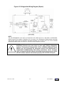
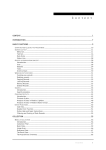
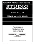
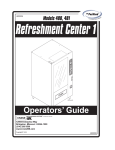
3. The 748 must be leveled. Perform level
adjustment by using the following illustration:
Place level in the (A) position and adjust the
bottom leg levelers. Perform same on position
(B) then (C).
APi 748 V1.1 406
1.3
A
C
B
DOOR
Place level in position A, and adjust the bottom
leg levelers, and repeat in positions B & C
Figure 1-1. Level Adjustment
CAUTION! If the 748 is not
leveled correctly the
refrigerator evaporator may
ice up, causing the unit to
shut down.
4. Ensure that circuit breakers are firmly in place
and the fluorescent lamps are secure in their
sockets.
5. Ensure that the Main Power Switch is in the
OFF position.
6. Plug the line cord into a dedicated, properly
grounded receptacle capable of delivering the
required power.
CAUTION – DO NOT
DEFEAT THE SAFETY
GROUND
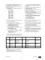
7. Install a supported coin changer (see chart
below).
a) Check coin chute alignment
b) Check coin return lever operation
c) Adjust if necessary
8. Install a bill acceptor if desired. Note: If you use
a MDB coin mech, you must use a MDB bill
acceptor or card reader. (See chart below).
9. If using FIFO mode, insert the selection
number labels in the corresponding Delivery
Doors. From top to bottom, the door
numbering convention is: 01, 02, 03, 04, 11,
12, 13, 14, 21, 22, 23. You only need to label
those shelves you intend to operate in the
FIFO mode.
10.Check and ensure that all electrical
connections are seated properly, especially at
the circuit boards.
P/N 77500001
Back
messages, then proceed to the next step.
13. Check that all fluorescent lamps are
illuminated.
14. Check the Service Switch operation by
rotating the turret one full rotation.
15. Close the main door.
16. Ensure that both the LEDs on the 748
Machine Controller are lit.
17. Perform a full initialization to reset the
machine to factory default settings.
a) Press MODE switch if Display does not read
“- - - SERVICE MENU - - -”.
b) In the Service menu, press [0], [0], [1], [0].
c) After each key press the display will show:
“- - - DIAGNOSTICS - - -”
“FULL INITIALIZATION NO”
“FULL INITIALIZATION YES”
“- - - - - - - - - - - - - - - - - - - -”
NOTE: The main door must be closed to prevent
an error message from occurring.
11. Turn the Main Power Switch ON (leaving Coin
Compartment and Main Doors open).
12. At power-up the following sequence of
displays should occur:
a) The Column Price Displays will show from
top to bottom:
“11111” “99.95”
“22222” “99.95”
“33333” “99.95”
“44444” “99.95”
“55555” “99.95”
“66666” “99.95”
“77777” “99.95”
“88888” “99.95”
“99999” “99.95”
“AAAAA” “99.95”
“bbbbb” “99.95”
Note: After you’ve set the prices, the actual
prices will be displayed.
18. Program the Cash System Type for the type of
coin changer and/or bill validator you will be
using (see page 3-7 of Section 3).
19. Power the 748 OFF then back ON.
20. Finish setting up the Cash System options
(see Section 3).
21. Ensure the RL Tx LED on the Credit Module is
flashing. Ensure the STATUS LED on the
Credit Module is operating correctly (refer to
Credit Module Indicators in Section 4).
22. Set up prices and options (see Section 3).
b) The Message Center should display:
1) “748 DISPLAY Vx.xx” (x.xx=version of
Message Center software), then
2) “API INTERNATIONAL”, then
3) “SHOWCASE MERCHANDISER”
4) “748 VERSION x.xx” (x.xx=version of 748
Machine Controller) then
5) “ONE MOMENT”, then
6) “- - - TURN TILL ZERO - - -”, Press
[RESET] key on Message Center.
Display should change to
“- - - MACHINE OK - - -”.
*If other messages appear than those listed
above, refer to page 3-2 to process those
Micro Mech
24V 15 pin2
Pulse Validator 24 V
Executive3
MDB Coin Mechanism 1
MDB Bill
Validator
Mars
TRC-6010XV
VN4010XV
540
560
TRC-6510
TRC-6512
VN-4510
VN2502-U5M
VN2512-U5M
CoinCo
9302 LF
USD-L701
USQ-L701
VN2502-U5E
VN2512-U5E
VFM1-L2-U4C
VFM3-L2-U4C
BA32SA
BA32R
BA32SA
BA32R
Conlux
USLX-001-01F
9302-GX,
USQ-G701
USO-G703
USQ-L701
USLZ-004-01F
CCM 5 G
USLZ-004-01F
Notes:
1. MDB Protocol - Use Harness R-28203401
2. Logic Protocol (“Dumb”)
3. Executive Protocol - Use Harness R-28203301
APi 748 V1.1 406
1.4
P/N 77500001
Back
Section 2: Description
INTRODUCTION
The 748 Showcase® Merchandiser has a maximum capacity of 154 items. It is capable of 3-level pricing and
3-level discounts controlled through Event scheduling. Individual selections can be reserved and sold on
specific or multiple shifts. The 748 Machine Controller permits individual programming to vend either FIFO
(First In/First Out) mode or Shopper mode by shelf. See the sections on Options and Service Mode for
instructions on setting prices and various options.
The Message Center uses point-of-sale messages to help customers make purchases while the 748
Machine Controller collects and accumulates audit information.
In the event of a system malfunction the 748 Machine Controller saves a history of specific events,
temperatures, and error messages which will help to quickly isolate the problem and return the vendor to
service.
Hot Keys
Several hot keys are used to display specific information from the outside of the while the machine is
running. A hot key sequence is performed by first pushing and holding the [RESET] key then pushing a
number key. Hot keys are defined as:
Hot Keys
Reset +
0
1
2
3
4
5
6
7
8
9
APi 748 V1.1 406
Display Shows
Display machine ID number
Display food compartment temperature
Display health control status
Display error time and date (if shutdown)
Not used
Display time and day
Display date
Not used
Display 748 software version number
Display serial number
2.1
MACHINE ID 12345678
TEMP = xxF xxC C
HEALTH CONTROL ON
OFF hh.mm AM mm-dd-yyyy
hh.mm AM DAY
mm-dd-yyyy
CONTROL MODULE xx.xx
SERIAL # 12345678
77500001
Back
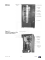
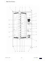
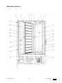
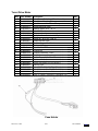
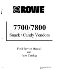
Figure 2-1:
Front View
Figure 2-2:
Coin Mech Compartment Door
Shown in Open Position
APi 748 V1.1 406
2.2
77500001
Back
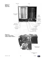
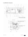
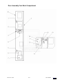
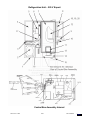
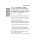
Figure 2-3:
Main Door
Open View
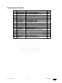
Figure 2-4:
Power Supply Panel
Shown in Open Position
APi 748 V1.1 406
2.3
77500001
Back
MAJOR COMPONENTS
748 Machine Controller
The 748 Machine Controller controls and monitors
the 748’s performance. It also:
keeps track of real time
controls the vend process
monitors food compartment temperatures
stores prices, option settings, and scheduled
events
records specific events and error messages
accumulates cash and sales data
controls the other four major components:
Message Center
Credit Module
Column Price Displays
Refrigeration/Turret Module
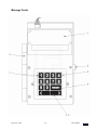
Message Center
The Message Center contains a 20-character
vacuum fluorescent display for customer
messages and prompts, turret rotation keys, and
selection number keys. The selection number
keys are also used in Service Mode to perform
service mode functions.
Credit Module
The Credit Module will interface the 748 Machine
Controller to various credit devices including coin
changers, bill validators, and card readers. It can
support several different credit device interfaces
including pulse, serial, MDB, and Protocol A.
Column Price Displays
The Column Price Displays are the five-digit
vacuum fluorescent displays down the center
column of the machine. These displays will show
pricing and status of selection compartments.
Refrigeration/Turret Module
The Refrigeration/Turret Module controls the
modular refrigeration unit in the 748 and reports
the temperature to the 748 Machine Controller. It
also drives and monitors the turret motor and half
cycle switch as commanded by the Machine
Controller.
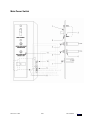
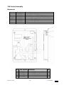
Main Power Switch Assembly
This assembly is located in the bottom left corner
of the cabinet. It houses the Main Power ON/OFF
switch along with the Refrigeration Interlock
Power Switch, a switch which opens the
refrigeration circuit to prevent frost buildup
whenever the main door is open. It also contains
two circuit breakers to protect the machine from
an overload.
APi 748 V1.1 406
2.4
Service Switch
This switch is located along the inside edge, on
the hinge side of the Main Door. It is a momentary
rocker switch that can be used to rotate the turret
when cleaning or filling the machine with product.
Main Door Interlock Switch
This switch is located on the inside of the main
door near the cash box. It will open when the main
door is open or ajar. This switch must be closed
when the coin mech compartment door is closed
to prevent an error.
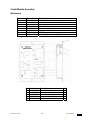
Storage Shelf Assemblies
A four-shelf storage rack is located along the right
wall of the cabinet. This rack is intended to store
nonperishable pre-cooled products to be used at
the next servicing.
Turret
The turret can be rotated in both directions using
the turret rotate keys on the Message Center. At
each subsequent power up, the turret
automatically rotates until the 748 Machine
Controller senses that the turret is at the “home”
position. If the turret is already “home” or any door
is open (delivery, main or coin mech
compartment), it will not rotate on power up.
Electronic Digital Thermometer
The electronic temperature sensor is located in
the return air compartment of the evaporator
under the evaporator screen. The temperature
sensor is used to monitor the temperature of the
cabinet interior (food compartment) by the
Refrigeration/Turret Module, which in turn,
controls the refrigeration unit and reports the
temperature to the 748 Machine Controller. The
Machine Controller uses the reported temperature
to run the Health Control feature. Should the
Refrigeration/Turret Board fail, the temperature is
controlled by manual thermostat located on the air
return plenum of the refrigeration unit.
To read the interior cabinet temperature while the
machine is running in the vend mode, push HOT
KEY 1 (push and hold the [RESET] button then
push the [1] button).
See page 2.1 for a description of all Hot Keys.
77500001
Back
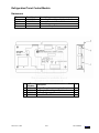
Relay Interface Board
Located on the inner front door near the lower hinge,
this board contains the energy control relay for the
door heaters, the turret motor interlock relay, and the
lights relay. It also provides rectified 24VDC for coin
mechanisms and rectified and filtered 24VDC used
to power all of the logic boards.
Delivery Door Defrost Blower
To prevent fogging in high humidity environments, a
defrost blower and heater system is provided (see
Figure 2-3). This blower can be switched off in low
humidity environments to save on energy
consumption.
Energy Control
The heating element in the Defrost Blower unit is
controlled by the Energy Control Relay and is
switched off whenever the refrigeration compressor
is on. The electric heater for the frame of the heated
glass window is also controlled in the same manner.
This system provides adequate protection against
window/delivery door fogging, and at the same time
reduces energy consumption.
REFRIGERATION
Electrical
The self-contained refrigeration system is designed
to slide in and out of the 748 as one complete
assembly. A normal 3-pin AC power cord supplies
power to the refrigeration system. The evaporator
blower runs continuously while AC power is applied,
regardless of the temperature in the food
compartment. The condenser fan runs only when the
compressor is running. The compressor and
condenser fan are controlled by a relay on the
Refrigeration/Turret Module.
When the main door is opened, the Refrigeration
Interlock Power Switch opens, turning off power to
the refrigeration system. When the main door is
closed, the evaporator blower starts immediately, but
there is a one-minute time delay before the
condenser fan and compressor will be turned on.
This delay reduces high torque starting of the
compressor due to rapid ON/OFF cycling.
Electronic Temperature Sensor
As described above, the temperature sensor is
located in the return air compartment of the
evaporator under the evaporator screen.
NOTE: The compressor control processing is
controlled by the Refrigeration/Turret Module and is
independent of the health control processing which
the 748 Machine Controller handles. If the 748 goes
out of service, the compressor control processing will
continue to operate.
temperature to voltage, which is monitored by the
Refrigeration/Turret Module. The temperature is
transferred to the 748 Machine Controller where it is
used for Health Control processing.
Compressor Algorithm
The compressor will turn on one minute after closing
the main door and will stay on for 20 minutes or until
the food compartment temperature falls below the
low temperature range setting. If the temperature
does not reach the low setting within 20 minutes, the
compressor will turn off for two minutes then turn
back on for another 20-minute period. This 20minute on, two-minute off cycle will continue until the
food compartment temperature falls below the low
temperature range setting.
Once the temperature in the food compartment falls
below the low temperature range setting, the
compressor will turn off for at least three minutes.
After three minutes, if the temperature rises above
the high temperature range setting, the compressor
will turn on for no more than 30 minutes.
Health Control
After opening and closing the main door, the
machine has 30 minutes in which to bring the
cabinet interior (food compartment) temperature
below the maximum temperature range setting. If
the temperature is still above the maximum
temperature setting, a 15-minute grace period
begins. If this grace period finishes and the
temperature is still above the maximum temperature
range, the machine will go out of service.
To display the amount of time remaining in the pull
down period, press hot key 2. “HEALTH DELAY XX
MIN” will appear on the display, where XX is the
number of minutes remaining from the original 30minute limit.
After the 30-minute pull down period expires or the
food compartment temperature reaches 41°F,
pressing hot key 2 will display “HEALTH CONTROL
ON”. This indicates that the food compartment
temperature is being monitored per Section 700 of
the NAMA Construction Standard for Refrigerated
Food Vending Machines.
If the machine should exceed the NAMA food
compartment temperature requirements, it will
shut down with a “HEALTH TIME OUT” error. To
reset a “HEALTH TIME OUT” error, you must first
clear the error then open and close the main door.
The temperature sensor is a solid-state temperature
transducer. This temperature sensor converts
APi 748 V1.1 406
2.5
77500001
Back
OPERATION
Normal 748 machine operation will find the 748
food compartment within the storage temperature
range, fluorescent lamps lit, all delivery doors
locked, column price displays showing the prices
of each adjacent compartment, and the Message
Center scrolling the point-of-sale message.
Point-of-Sale Messages
The Message Center will display several
messages to the customer during the vend
process. Each possible message is described
below.
INSERT MONEY - MAKE SELECTION - This is
the default point-of-sale message. This message
will scroll across the Message Center display
while waiting for a customer to insert money. This
message may be changed in the service mode.
USE COINS ONLY - This message will appear
when the coin changer is too low on coin tube
coins to make change for bills but there is
sufficient change to give change for coins.
USE EXACT COINS ONLY - This message will
appear when the coin changer is low on the
smallest-valued coin tube coin.
THANK YOU - Displayed after a customer makes
a selection.
NOT ENOUGH CREDIT - This message is
displayed when a customer tries to make a
purchase but has not inserted enough money.
ITEM ALREADY SOLD - This message is
displayed when a customer tries to purchase a
selection that has already been sold.
ITEM IS NOT AT DOOR - This message is
displayed when a customer attempts to purchase
a selection on a full width compartment and the
turret is in a half compartment position.
CLOSE ALL DOORS - This message will be
displayed when more than one delivery door is
opened at the same time.
CLOSE DOOR xx - This message is displayed
when a customer tries to rotate the turret when
one delivery door is not closed.
SELECTIONS SOLD OUT - This message is
displayed when the token option is set to
“PRODUCT CODE” and a token is inserted with
no selections available within the programmed
product code range.
MAKE FREE SELECTION - The 748 is set to free
vend. No money is required or token vend is
made with token option set to “FREE ANY” (see
Token Options in Section 3).
WINNER - This message is displayed when the
free vend odds option is turned on and a customer
makes a selection and wins a free vend.
MACHINE SHUTDOWN UNTIL hh.mm – This
message is displayed whenever the machine has
been shutdown due to event scheduling (the
Timed-Lockout feature). hh.mm is the time the
machine will return to normal operation.
RESERVED SELECTION - This message is
displayed when the Sell By Shift option is active
and a customer attempts to buy an item that is
reserved for another shift or purchase an item that
is reserved for token purchase only.
SORRY OUT OF SERVICE - This message will
appear when there is an error condition detected
in the 748. Money acceptance is inhibited and the
fluorescent lamps are turned off.
VALIDATING CARD - This message will appear
when a customer attempts to purchase a selection
using a card in a card reader.
CREDIT x.xx - This message shows the customer
how much credit has been established on the
machine.
CHANGE x.xx - This message shows the amount
of change that is being returned to the customer.
MAKE SELECTION - This message will be seen
when a token vend is made with the token option
set to “PRODUCT CODE” (see Token Options in
Section 3).
NO CHANGE - This message will be displayed
when a large bill is inserted into the bill validator
and there is not enough change in the coin
changer to make change. The bill will be returned
to the customer.
PRESS SELECTION xx - This message is
displayed when a customer attempts to make a
selection on a shelf set to FIFO (first-in-first-out)
APi 748 V1.1 406
2.6
77500001
Back
mode and the turret is not positioned at the first in
product. The customer must select xx using the
keypad.
SELECTING SHELF xx - This message is
displayed after the first digit of a FIFO selection
has been make.
ONE MOMENT - This message is displayed while
the turret is rotating into position after a FIFO
selection has been made. This message will also
be displayed after closing the coin changer
compartment door while leaving the Service
Mode.
SHELF NOW READY - This message is displayed
during a FIFO purchase after the turret has moved
into the vend position.
Price Column Displays
The price column displays will show the status of
each compartment as the turret is rotated and
during purchases. The different status messages
that can be seen on the price column displays are
discussed below.
nn.nn - This indicates the price of the item in a
compartment. (n = any digit 0 - 9)
SoLd - This indicates the item in a compartment
has already been sold.
OPEn - This indicates the door to this
compartment is unlocked and the item can be
removed.
- - - - - This indicates that the turret is not lined up
with the delivery door or that this item is reserved
for another shift.
[ ] This is displayed on each compartment that has
been sold during the Sold Out Check
operation.
] - - - [ This is displayed on each sold
compartment that has been cleared during Sold
Out Check operation.
AVAIL - This indicates which items are available
for purchase when a token is inserted into the bill
acceptor and tokens are not set up as a cash
value.
(See Token Options in Section 3.)
PROGRAMMABLE OPTIONS
The 748 has several programmable options.
Some options can simply be turned on or off,
where other options can be scheduled to turn on
or off at programmed times. Below is a summary
list of the options available in the 748. Settings
listed in bold are the default settings. Further in
this section are descriptions of each option, what
it does, and how to set it up. See Section 3 for
specific key commands to set specific option
parameters.
OPTIONS
• Free Vend
• Sold Out Check
• Force Vend
• Random Free Vend
• Shutdown
• Multiview
• Discount
• Sell by Shift
• Pricing
• Show Sold
POSSIBLE SETTINGS
On or Off
On or Off
On or Off
xxx:1 or Off
On, Off or PER SCH
On, Off or PER SCH
Off or PER SCH
Off or PER SCH
Normal or PER SCH
Off or On
OPTIONS EXPLAINED:
Free Vend
The Free Vend option will simply show all prices
at 0.00 and allow items to be vended without
credit. Normally, communication with a coin mech
is required or the 748 will shutdown; however,
with Free Vend turned on, the coin mech is
ignored.
Sold Out Check
This option is used to help determine whether a
compartment has been refilled with possibly
tampered food. This option may be bypassed by
pushing the [RESET] key.
Force Vend
This option is designed to force a purchase after
bills and/or coins are deposited into the 748. Any
attempt to return credit using the coin return will
be refused. Change will be returned only after a
purchase is made.
Random Free Vend
Random Free Vend is intended to free vend a
selection on a random basis using a pre-selected
occurrence level. The FREE VND ODDS item in
the service mode can be programmed OFF or any
range of odds from 50:1 to 3000:1 in steps of 50.
This option sets the odds of winning, so setting
50:1 odds does not guarantee one winner every
50 vends. However, after several thousand vends,
the average number of free vends will be 50:1.
APi 748 V1.1 406
2.7
77500001
Back
Shutdown and Timed Lockout
The Shutdown option can also be set to ON. This
will cause the 748 to immediately go into
shutdown when the coin door is closed. To restore
the machine to vend mode, the coin door must be
opened and the Shutdown option must be turned
OFF. This can be used to prevent sales or turret
activity when service activities are in process.
The 748 supports a TIMED LOCKOUT feature
which may be programmed to prohibit sales at
specified times during the week using a scheduled
event.
When the 748 is shutdown due to such a
scheduled event, the machine lights will be off and
a message will be displayed on the message
center showing “MACHINE SHUTDOWN UNTIL
xx.yy”, where xx.yy is the time when the machine
will go back into service. During programmed
shutdown, the refrigeration and health control
systems continue to work normally.
The shutdown option must be set to “PER SCH”
and a shutdown event must be programmed in the
event schedule.
Multiview
When Multiview is turned on, the turret is rotated
three positions every three minutes of idle time.
Multiview is used to draw attention to the 748 and
to periodically move the food in the refrigerated
compartment
to
provide
more
uniform
temperature control.
Multiview can be turned on or off or can be
scheduled to turn on and off at specified times of
the day using a scheduled event.
EXCEPTION: If the operating temperature range
is set for 1°C - 3°C, the multiview option cannot be
disabled or turned off.
APi 748 V1.1 406
2.8
Discount
Three different discounts may be programmed.
Discount amounts will be subtracted from the
regular price whenever that discount becomes
active. The prices on the price display will reflect
any active discount. If the discount amount is
greater than the price of a selection, the price of
that selection will be 0.00. To use discounts, the
Discount option must be set to “PER SCH”, a
discount amount must be set, and a discount
event for that discount must be programmed in
the event schedule.
For example: Discount 1 is set to $0.10 and a
scheduled event turns on Discount 1 on Friday at
17:00 then off on Saturday at 22:00. All displayed
on the price display between those times will have
$0.10 subtracted from them.
Sell By Shift
Sell By Shift allows reserving selections for sale at
a specific time. Each compartment can be
individually reserved for sale on specific days of
the week and hours of the day.
When someone tries to open the door to a
selection that is reserved for a nonactive shift, the
display will show “RESERVED SELECTION”.
Pricing
Three different prices (price schedules) may be
set for each selection compartment. If the pricing
option is set to “NORMAL”, only price schedule 1
is used. If the pricing option is set to “PER SCH”,
then the pricing schedule can be programmed
using scheduled events. Any time not defined by a
specific schedule will default to price schedule 1.
Show Sold
With this option ON, when a “sold” compartment is
in the vend position, its corresponding price
display will show “SoLD” instead of the item’s
price. With the option set to OFF, prices will be
shown for all compartments in the vend position
even if the item has been sold.
77500001
Back
SCHEDULED EVENTS
Up to 25 scheduled events may be programmed
into the 748. A scheduled event is an option that
is turned on and off based on time of day and the
day of the week. The options that may be
programmed as events are:
• SHUTDOWN
• MULTIVIEW
• SHIFT 1
• SHIFT 2
• SHIFT 3
• PRICE 1
• PRICE 2
• PRICE 3
• DISCOUNT 1
• DISCOUNT 2
• DISCOUNT 3
FIFO Vend Mode
The 748 can be set up to vend items on a shelf in
a First-In-First-Out (FIFO) mode. This is a way to
ensure the oldest product on a shelf is purchased
first. Each shelf can be individually set to operate
in the FIFO mode. If not in the FIFO mode, a shelf
will be in the normal shopper (SHOP) mode.
Each shelf is assigned a two-digit shelf number.
This number is used when making a purchase on
a FIFO shelf. Normally, the customer just opens
the delivery door of the selection they want. FIFO
requires the sale of the oldest product first so the
customer cannot just open any door. If the oldest
product happens to be in the right place, the door
will open. Otherwise, a message on the display
will read “PRESS SELECTION xx” where xx is the
shelf number. When the customer enters shelf
number xx on the keypad, the 748 will rotate to
present the oldest product on that shelf and allow
the customer to make the purchase.
Day of the week selections include:
MON - Monday
TUE - Tuesday
WED - Wednesday
THU - Thursday
FRI - Friday
SAT - Saturday
SUN - Sunday
WKD - Week days (Monday - Friday)
ALL - Everyday
As the customer is entering the shelf number, the
display will show “SELECTING SHELF x” when
the 1st digit is pressed. Then, the display will show
“ONE MOMENT” as the turret rotates into
position.
Then finally the display will show
“SHELF NOW
READY”, indicating the product is in position to be
purchased.
An event is any scheduled change in an option.
For example, Multiview may be scheduled to turn
on at 17:00 and turn off at 8:00 Monday through
Friday. This would be considered one event, even
though Multiview will be turned on and off each
day, Monday through Friday.
To get an option to turn on and off based on a
schedule; two things must be set up. First, set the
option to “PER SCH”. Second, program the event
in the event schedule.
Be sure to insert the shelf number labels into the
label holder on the back of the Delivery Doors so
customers know the shelf number to select.
To reset the FIFO index for a shelf, use Service
Mode function [3][3] and re-configure the shelf as
a FIFO shelf. This will reset the index for that shelf
to the first vend position (home position on the
turret).
When programming an event in the schedule, the
event type, on time, and off time must be set. On
times and off times can be set to occur on the
same day (on at 8:00 Monday, off at 16:00
Monday), on subsequent days (on at 8:00
Monday, off at 17:00 Friday), on every day of the
week, or on just Monday through Friday.
APi 748 V1.1 406
2.9
77500001
Back
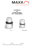
FIFO MODE OPERATION
Start Point, Full Shelf
After initialization, items are sold in sequential
order as shown here. On subsequent refills, the
actual position of the item to be sold next depends
solely on the last item sold. The next item sold is
always immediately to the left of the previously
sold item.
After items are sold and you return to refill the
machine, a typical FIFO shelf might look like this.
If not, use Service Switch to rotate the turret until
the remaining products are positioned as shown.
The next product to load here is at Position 1. The
rule to follow is use the Service Switch to rotate
the turret until the last remaining product is on
your right, and then reload the shelf from right to
left.
The selling sequence after loading this shelf
would be 12, 13, 14, 1, 2, etc.
Special Situations
The first special situation is when you find one or
more completely sold out FIFO shelves. If you can
fill every selection, there is no problem. If you do
not have enough product to fill every location, you
won’t know where to begin loading.
If you have the “CHECK SOLD OUT” option ON
(Options Menu), you will be prompted to do so
when the coin door is opened. If so, check all the
SOLD compartments (or press [RESET] to skip
this check). Once the Display shows “- - MACHINE OK - - -”, turn the turret to the zero
position. Pressing the MODE switch will change
the display to “- - - SERVICE MENU - - -”. Then
pressing [3][3] will cause the display to read
“- - - PRICES – SHELVES - - -”, then “SHELF
MODE xxx”, where xxx is FIFO or SHOP. If
necessary, use [1] to toggle to FIFO, then actuate
the delivery door of each of the completely sold
out shelves. This will reset the shelf so that the
first item sold will be that at Position 1. Begin
filling the empty FIFO shelves in sequence – 1, 2,
3, 4, etc. as the arrow to the left describes.
the Display will show “SET FIRST EMPTIES”. For
every partially filled FIFO shelf, rotate the turret
until the last available product is just to the right of
the Vend position. With the first empty
compartment at the vend position, actuate the
corresponding delivery door. The computer will
then mark the compartments from there to the
next-to-sell product as being Previously Sold. In
the example at the left, compartments 9 through
14 would be marked as Sold.
Filling the Machine
In order to prevent the sale of an item replaced in
the machine by a customer, the 748 keeps track
of the compartments that have been sold and
prevents those doors from being opened again
before you open the machine and fill it. Because
of this, the machine must be aware that you’ve
filled the machine.
If you open the coin compartment door and then
open the Main Door and press the Service Switch
without first pressing the MODE switch on the
Main Controller, the 748 will assume that the
machine is being filled and as such will reset all
compartments
to the unsold state.
Pressing the MODE switch on the Main Controller
before operating the Service Switch will cause the
748 to assume that there is a service call in
process, and it will allow turret rotation without
affecting the sold state of any of the
compartments.
This process is the same for all shelves whether
in Shopper Mode or FIFO mode. Shelves that are
in FIFO mode will resume sales from the previous
point, so you still have true FIFO operation even
after filling.
If for any reason you cannot completely fill a FIFO
shelf, you can eliminate the possibility that a
customer will open an empty selection (“buy air”)
by using the “SET FIRST EMPTIES” feature.
To use this feature, the “CHECK SOLD OUT”
option must be ON.
When the “CHECK SOLD OUT” option is ON and
the Main Door is closed after filling the machine,
APi 748 V1.1 406
2.10
77500001
Back
Section 3: Service Mode
Introduction
The 748 uses a menu driven interface to set up
the machine, retrieve audit information, and
troubleshooting assistance.
Opening the Outer Door (Monetary Door)
Opening the Coin Compartment Door will put the
machine is service mode. This will prompt the
display to change to one of the following
messages:
“- - - MACHINE OK - - -”
“- - - ERRORS EXIST - - -”
“CHECK HISTORY LOG”
“TURN TILL ZERO POSITION”
“CHECK SOLD OUT DOORS”
“- - - MACHINE OK - - -”
The machine is operating normally, Press
MODE switch on the Machine Control Board, the
Display will change to “- - - SERVICE MENU - - ”. In this mode you can set up the machine
options and retrieve sales information (see page
3.X).
“- - - ERRORS EXIST - - -”
If the machine is out of service, the Display will
prompt “- - - ERRORS EXIST - - -”. Pressing
the MODE switch on the Main Control Board will
cause the Display to change to the error
description. Pressing the “RESET” key will
cause the Display to change to “CLEAR
ERRORS NO” unless a Health Timeout Error
occurred after the original error. If this
happened, the Display will show “HEALTH TIME
OUT” and you must press the [RESET] button a
second time to reach the “CLEAR ERRORS NO”
message. To clear the error(s) press the [1] key
to change from “NO” to “YES” and then press
the [0] key (the Display will show “ERRORS
CLEARED” and then proceed to the next
applicable message). You may proceed to the
next applicable message without clearing the
errors if desired by pressing the [RESET] key.
Note: Errors are not cleared until the Service
Mode has been exited by closing the Coin
Compartment Door. Errors will not be cleared if
the power is lost before re-entering Vend Mode.
A Health Timeout Error will not be cleared
unless you open the Main Door. This action lets
the computer system “know” that you have
examined the food and taken any necessary
steps to insure that it is safe for consumption.
the machine, always check the Error History before
putting the machine back into service.
Refer to Section 4: Troubleshooting to help resolve
any reported errors. There is an error log that will
retain the last 20 errors that occurred. Refer to
“History” in the Section 4: Troubleshooting to view
and/or print the error history.
CHECK HISTORY LOG
If a non-shutdown event (such as a bill jam)
occurred since the last servicing, “CHECK
HISTORY LOG” will be displayed. If from a
preceding error condition, press [RESET] to
continue. Otherwise, press the MODE Switch to
continue. It is recommended that the History Log be
checked for non-shutdown events upon entering the
service menu. See KEY [4] - History in this section.
TURN TILL ZERO
This message is displayed when the Turret Position
has not been initiated. To initiate the
Turret Position, rotate the turret using the Turret
Keys until “ZERO POS FOUND” is displayed on
Message Center. At this time the Center Price
Display will be updated to reflect current pricing and
the Sold display is updated. Turn Till Zero function
may be aborted by pressing the [RESET] key. In
this case, some functions in service mode, including
pricing can not be accessed until the Zero Pos has
been found.
CHECK SOLD OUT DOORS
The Check Sold Out Doors feature is used to verify
that a compartment has not been refilled with
potentially tampered food or other objects.
When this option is ON, the display will show
“CHECK SOLD OUT DOORS”. The price display at
each delivery door will show “[ ]” if that
compartment should be empty. Open each
compartment door and remove anything that might
be in the compartment (tampered food, trash, etc.):
the display will change to “] --- [”. Rotate the turret
and check all compartments that show “[ ]”. Once all
compartments have been checked, dashes will
flash on all price displays and the display will go to
the next applicable message.
As an alternate method, you may visually check all
of the sold compartments, and then press the
[RESET] key or open the Main Door to exit this
function.
Since the Control Board continues to monitor all
systems even while it is out of service, other
errors may have occurred during the downtime.
To be certain that there are no other problems in
APi 748 V1.1 406
3.1
P/N 77500001
Back
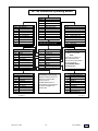
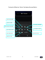
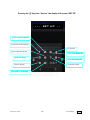
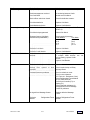
AP 748 Showcase Operating Modes
HOT KEYS
----DIAGNOSTICS--00
01
02
03
04
05
06
07
08
09
FULL INITIALIZE
TEMPERATURE STATUS
TIME OVER HEALTH
HEALTH TEST
SOFTWARE VERSIONS
LOG TO PRINTER OFF
DRIVER TEST
20
21
22
23
24
25
26
27
28
29
FREE VEND
PRICING
DISCOUNT
MULTIVIEW
SELL BY SHIFT
SHUTDOWN
SOLD OUT CHECK
MACHINE ID NUMBER
INTERIOR TEMPERATURE
2
3
4
5
6
7
8
9
HEALTH CONTROL STATUS
ERROR TIME AND DATE
NOT USED
TIME AND DAY
DATE
NOT USED
SOFTWARE VERSION
SERIAL NUMBER
INPUT TEST
COIN COMPARTMENT OPEN
PRESS MODE SWITCH TO ACCESS
----OPTIONS---
FORCE VEND
FREE VEND ODDS
--PRICES - SHELVES-30
31
32
33
34
35
36
37
38
39
Reset +
0
1
SCH PRICE
SHELF SIZE
SHELF MODE
DISCOUNT =
PRODUCT CODE
SELL ON SHIFT
SHOW SOLD
Menu # --- ----SERVICE MENU--0
1
2
3
4
5
6
7
8
9
----DIAGNOSTICS--.xx COIN yy z.zz
---OPTIONS-----PRICES - SHELVES-----HISTORY--CASH SYS TYP
---SET UP--DISPLAY AUDIT DATA
SECURITY CODE
VIEW HISTORY LOG
VIEW ERROR LOG
VIEW TEMP LOG
CLEAR HISTORY LOG
CLEAR ERROR LOG
CLEAR TEMP LOG
PRINT LOGS
5 - PAYMENT SYSTEMS
MDB ,DUMB or Executive Devices
See Manual for set up details.
NOTE:
After changing any setting, you
MUST power machine OFF
OFF, then ON to properly initialize
the payment periherals!
DO NOT MIX MDB, DUMB or
Protocol A Devices
DISPLAY AUDIT DATA
Press [0] key to step through
Display Audit Data. When you
reach the end of the data,
display will show:
CLEAR AUDIT DATA N
Press [1] key to toggle between
Y and N, Press [0] to clear
interval data.
P/N 746000xxx
APi 748 V1.1 406
----HISTORY--40
41
42
43
44
45
46
47
48
49
----SET UP--70
71
72
73
74
75
76
77
78
79
SET SCHEDULED EVENTS
P.O.S. MESSAGE
SERIAL#
MACHINE ID
SET DATE
SET TIME
TEMP RANGE
DATE FORMAT
BAUD RATE
LANGUAGE ENGLISH
Rev 1 Sept 03
3.2
P/N 77500001
Back
ACCESSING SERVICE MENUS
Access to all service menus starts with the
Message Center showing “- - - SERVICE MENU
- - -”. If the display shows something different,
push the [RESET] key to return to the top of the
service mode.
Generally, service mode functions have been
grouped together based on their function and
assigned to a common key. Most service mode
functions require two key strokes. The first key
selects the group, and the second key selects
the specific function.
After entering the one or two keys to display the
desired service mode function, the keys are
again used to make changes to that function.
APi 748 V1.1 406
3.3
The service mode function groups and the keys
they are assigned to are:
[1] Load and calibrate coin tubes
[2] Set up 748 options
[3] Set prices and shelf parameters
[4] View and/or print history logs
[5] Set cash system type and options
[6] Not used
[7] Set up 748 machine parameters
[8] Display/print/download audit data (DEX)
[9] Security
[0] Diagnostics
The remainder of this section describes how the
keys are used in each service mode function with a
quick summary of the function itself. For a more
complete description of a specific function, refer to
the section where that function’s operation is
described.
P/N 77500001
Back
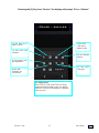
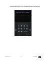
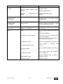
Pressing the [1] Key from “Service” the display will prompt the coin mech inventory.
#1 Key
*Increments the
value of coins in the
tube
#2 Key
*Decrements the
number of coins
in a tube.
#5 Key
Dispenses 1st coin
from tube.
#7 Key
Dispenses 3rd
coin from tube.
#6 Key
Dispenses 2nd coin
from tube.
#8 Key
Dispenses 4th
coin from tube
(if available)
#0 Key
Scroll through the
tube denominations.
* Not available if using an MDB coin mech with the tube sensing option set to “Auto”
APi 748 V1.1 406
3.4
P/N 77500001
Back
Pressing the [1] Key from
“Service” the display will prompt
the coin mech inventory
KEY [1]
Coin Tubes – The purpose of this function
is to allow the operator to inventory and
adjust the number of coins in the coin tubes.
Note: When an MDB coin changer is
installed and the TUBES option is set to
AUTO, this function will show the number of
coins in the tubes but will not allow manual
changes. The MDB coin changer keeps
track of the number of coins in the tubes and
reports the number to the controller. Also, if
an Executive type coin changer is installed,
the tube counts are not used at all.
If coins are manually added to the tubes
from the front of the changer, the coin count
must be adjusted in this menu. If coins are
deposited or dispensed while in this mode,
the display will automatically show the
inventory
count
of
the
last
coin
denomination.
DISPLAY: “.xx COIN yy z.zz”
xx is the value of the coins in a tube
yy is the number of coins in this tube
z.zz is the value of all coins in this tube
Key Function
[0] Scrolls through coin tubes
[1] *Increments the number of coins in a
tube
[2] *Decrements the number of coins in a
tube
[5] Dispenses from 1st coin tube
[6] Dispenses from 2nd coin tube
[7] Dispenses from 3rd coin tube
[8] Dispenses from 4th coin tube (if available)
[RESET] Returns to the top of the service
mode
*Not available if using MDB mech with the
TUBE sensing option set to “AUTO”.
NTE
When the dumb type coin changer is
selected and the TUBE sensing option is set
to “LEVEL”, the tube count will automatically
be adjusted when the level sensor in the
coin changer is covered or uncovered and
the coin tube counts will revert to their
default values.
APi 748 V1.1 406
3.5
P/N 77500001
Back
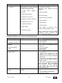
Pressing the [2] Key from “Service” the display will prompt Options
- - - Options - -
[2] Set Discount Mode
[1] Set Price Mode
[4] Set Sell by Shift Mode
[6] Set Sold Out Check Mode
[3] Set Multiview Mode
[5] Set Shutdown Mode
[9] Set Winner Odds
[8] Set Force Vend
[0] Set Free Vend
APi 748 V1.1 406
3.6
P/N 77500001
Back
Pressing the [2] Key from
“Service” the display will prompt
Options
Discount [2][2]
When this option is set to Per Schedule, it
allows merchandise to be sold at discount
prices at pre-set times.
KEY [2]
Options – This menu allows you to set the
the options available on the 748. Each
function in this service menu requires a twokey entry to run; the first key is [2], and the
second key is one of the following:
DISPLAY: “DISCOUNT OFF”
[1] Toggles between OFF and Per
Schedule
[0] Saves choice and returns to the top of
the service mode
[RESET] Returns to the top of the service
mode without saving choice
[1] Set pricing mode
[2] Set discount mode
[3] Set multiview mode
[4] Set sell by shift mode
[5] Set shutdown mode
[6] Set sold out check mode
[7] Not used
[8] Set force vend mode
[9] Set winner vend odds
[0] Set free vend mode
If you choose Per Schedule, go to the “Set
Schedules” menu [7][0].
Free Vend [2][0]
When this option is turned on, the machine
will vend for free.
MultiView [2][3]
This option allows MultiView to be turned on,
off, or to only run at scheduled times. If
MultiView is set to on, it will rotate the turret
three compartments for every three minutes
of idle time.
DISPLAY: “FREE VEND NO”
DISPLAY: “MULTIVIEW OFF”
[1] Toggles between YES and NO
[0] Saves choice and returns to the top of
the service mode
[RESET] Returns to the top of the service
mode without saving choice
[1] Toggles between OFF, ON, and Per
Schedule.
[0] Saves choice and returns to the top of
the service mode.
[RESET] Returns to the top of the service
mode without saving choice
Pricing [2][1]
When this pricing option is set to Per
Schedule, it allows merchandise to be sold
at different prices at preset times.
If you choose Per Schedule, go to the “Set
Schedules” menu [7][0].
Sell by Shift [2][4]
This option activates the sell by shift option.
DISPLAY: “PRICING NORMAL”
DISPLAY: “SELL BY SHIFT OFF”
[1] Toggles between NORMAL and Per
Schedule
[0] Saves choice and returns to the top of
the service mode
[RESET] Returns to the top of the service
mode without saving choice
[1] Toggles between OFF and PER
SCHedule
[0] Save choice and returns to the top of the
service mode
[RESET] Returns to the top of the service
mode without saving choice
If you choose Per Schedule, go to the “Set
Schedules” menu [7][0].
APi 748 V1.1 406
If you choose PER SCHedule, go to the “Set
Schedules” menu [7][0] on page 3-15.
3.7
P/N 77500001
Back
OPTIONS CONTINUED
Free Vend Odds [2][9]
Set or change the odds that determine when
a customer may win a free vend.
Shutdown [2][5]
This option allows you to leave the machine
fully functional from a health control
standpoint, but the lights stay off, turret
rotation is inhibited, and all credit inputs are
disabled. This action can be forced
immediately or at scheduled times. If there
is any credit on the machine when such a
period is entered, it will be returned
immediately.
DISPLAY: “FREE VND ODDS OFF”
Key Function
[1] Increments Odds from OFF to 3000 by
50
[2] Decrements Odds from 3000 to OFF by
50
[0] Saves choice and returns to the top of
the service mode
[RESET] Returns to the top of the service
mode without saving choice
DISPLAY: “SHUTDOWN OFF”
[1] Toggles between ON, OFF and PER
Schedule
[0] Saves choice and returns to the top of
the service mode
[RESET] Returns to the top of the service
mode without saving choice
If you choose PER Schedule, go to the “Set
Schedules” menu [7][0].
Sold Out Check [2][6]
When turned on, the 748 will prompt the
operator to check all Delivery Doors for
signs of tampering.
DISPLAY: “SOLD OUT CHECK OFF”
[1] Toggles between ON and OFF
[0] Saves choice and returns to the top of
the service mode
[RESET] Returns to the top of the service
mode without saving choice
NOTE: See section two
description of Sold Out Check.
for
option
Force Vend [2][8]
Turns the Force Vend option on and off.
DISPLAY: “FORCE VEND OFF”
Key Function
[1] Toggles between ON and OFF
[0] Saves choice and returns to the top of
the service mode
[RESET] Returns to the top of the service
mode without saving choice
APi 748 V1.1 406
3.8
P/N 77500001
Back
Pressing the [3] Key from “Service” the display will prompt “Price – Shelves”
-Prices – shelves-
[2] Sets shelf size to
HALF or FULL
[3] Sets shelf
vend mode to
SHOP or FIFO
[1] Sets prices and
schedules
[4] Sets discount
amounts
[5] Sets product codes
per compartment
[7] Sets show
sold option
[6] Sets shift
availability per
compartment
To Assign Price:
With correct price and schedule shown in display,
SLIDE DELIVERY DOOR to right. Price Display
adjacent to selection will immediately be updated to
reflect new price
APi 748 V1.1 406
3.9
P/N 77500001
Back
Pressing the [3] Key from “Service”
the display will prompt “Price –
Shelves”
Shelf Size [3][2]
This feature allows setting shelf sizes to
either FULL or HALF. The Column Price
Display will show the current shelf size
assigned to each shelf, either FULL or
HALF. Change shelf size on message
center until desired shelf size is shown.
Then toggle the Delivery Door to assign
shelf size to desired shelf. The Price Display
will update to show the new shelf size.
KEY [3]
Prices - Shelves – This menu allows setting
prices, price schedules, shelf size, product
codes, discounts, and shift availability. Each
function in this service menu requires a twokey entry to run; the first key is [3], and the
second key is one of the following:
[1] Sets prices and schedules
[2] Sets shelf size to HALF or FULL
[3] Sets shelf vend mode to SHOP or FIFO
[4] Sets discount amounts
[5] Sets product codes per compartment
[6] Sets shift availability per compartment
[7] Sets show sold option
[8] Not used
[9] Not used
[0] Not used
DISPLAY: “SHELF SIZE HALF”
[1] Toggles between HALF and FULL
[RESET] Returns to the top of the service
mode
Shelf Mode [3][3]
This feature allows setting the shelf mode
between normal (SHOP) vend mode and
First-In- First-Out (FIFO) vend mode. The
Column Price Display will show the current
mode. Toggle the Delivery Door to assign
the selected mode to a shelf. The Column
Price Display will update to show the new
mode.
Schedules/Prices [3][1]
Prices are set per shelf. Change the price
shown on the Message Center until the
desired price is shown. Then toggle the
Delivery Door to assign the new price to the
shelf. The Column Price Display will show
the new price. Shelf prices for all three
schedules are set with this function.
DISPLAY: “SHELF MODE SHOP”
[1] Toggles between SHOP and FIFO
[RESET] Returns to the top of the service
mode
DISPLAY: “SCH x PRICE y.yy”
x is the schedule number [1..3]
y.yy is the price
Discount [3][4]
This feature allows setting price discounts.
The discount range is between 0 and 2.00.
Key Function
[1] Increments price by coin scale
[2] Decrements price by coin scale
[3] Increments schedule number
[4] Decrements schedule number
[5] Increments shelf price by 10x the coin
scale
[6] Decrements shelf price by 10x the coin
scale
[RESET] Returns to the top of the service
mode
DISPLAY: “DISCOUNT x = .yy”
x is the discount number
yy is the discount amount
Key Function
[1] Increments discount amount by coin
scale
[2] Decrements discount amount by coin
scale
[3] Increments discount number
[4] Decrements discount number
[5] Saves changes and increments to next
discount
[0] Saves changes and returns to the top of
the service mode
[RESET] Returns to the top of the service
mode without saving choice
NOTE: Use [7][0] to set the ON/OFF times
for the schedules
APi 748 V1.1 406
3.10
P/N 77500001
Back
“Price – Shelves” Continued
Show Sold [3][7]
This feature allows setting the price column
display to show “SOLD” when an item is
sold or just display the item price.
Product Codes [3][5]
This feature allows setting product codes to
each compartment. The Price Display will
show the current product code assigned to
the compartments. Change the product code
on the Message Center until the desired
product code is shown. At this time if
product code is to be set to the entire shelf,
press [7]. Toggle a Delivery Door to assign
that product code to that specific
compartment or shelf. The Column Price
Display will update to show the new code.
Rotate the turret to assign codes to all
compartments.
DISPLAY: “SHOW SOLD ON”
Key Function
[1] Toggles between ON and OFF
[0] Saves choice and returns to the top of
the service mode
[RESET] Returns to the top of the service
mode without saving choice
NOTE: Press [7] before toggling door each
time that product code is to be saved to the
entire shelf.
DISPLAY: “PRODUCT CODE 00”
Key Function
[1] Increments product code
[2] Decrements product code
[5] Increments product code by 10
[6] Decrements product code by 10
[7] Applies product code to entire shelf
[RESET] Returns to the top of the service
mode
Sell On Shift [3][6]
This feature allows setting of shifts when
compartments are available to be sold. The
Column Price Display will show the current
shifts assigned to the compartments.
Change the active shifts on the Message
Center. At this time if current shifts is to be
set to the entire shelf, press [7]. Toggle a
Delivery Door to apply the new shift choice
to a specific compartment or shelf. The
Column Price Display will update to show
the new shift assignment. Rotate the turret
to assign shifts to all compartments.
NOTE: Press [7] before toggling door each
time that a new shift choice is to be saved to
the entire shelf.
DISPLAY: “SELL ON SHIFT 1-2-3”
[1] Selects/Deselects shift 1
[2] Selects/Deselects shift 2
[3] Selects/Deselects shift 3
[7] Applies shift selection to entire shelf
[RESET] Returns to the top of the service
mode
NOTE: When using this option, the on and
off times for shifts 1,2,3 must be set with the
Set Schedules Key [7][0].
APi 748 V1.1 406
3.11
P/N 77500001
Back
Pressing the [4] Key from “Service” the display will prompt “History”
--- History ---
[2] View the Error log
[3] View the
Temperature log
[1] View the History log
[5] Clear the History log
[7] Clear the
Temperature log
[6] Clear the Error log
[9] Print a selected log
APi 748 V1.1 406
3.12
P/N 77500001
Back
Pressing the [4] Key from “Service”
the display will prompt “History”
KEY [4]
History – This menu contains the Machine
History Log, Error Log, and Temperature Logs.
The operator may view, clear, or print logs from
this menu. Each function in this service menu
requires a two-key entry to run; the first key is [4],
and the second key is one of the following:
[1] View the History log
[2] View the Error log
[3] View the Temperature log
[4] Not used
[5] Clear the History log
[6] Clear the Error log
[7] Clear the Temperature log
[8] Not used
[9] Print a selected log
[0] Not used
AUTOMATIC PRODUCTS
748 VER xx.xx
--------------------HISTORY LOG
11:46 FRI 01-05-2001
--------------------8:37AM 1-02-01 DEFAULTS LOADED
10:36AM 1-02-01 POWER DOWN TIME
10:41AM 1-02-01 POWER UP TIME
12:42PM 1-02-01 MAIN DOOR OPEN
12:45PM 1-02-01 MAIN DOOR CLOSE
4:23PM 1-04-01 POWER DOWN TIME
8:05AM 1-05-01 POWER UP TIME
Error Log [4][2]
This log contains a list of errors the machine has
detected. This log includes the last 20 errors.
DISPLAY: “xx = logged error”
xx is the event number
View History Log [4][1]
This feature allows the operator to view the last 50
events in the History Log.
DISPLAY: “xx = logged event”
xx is the event number
logged event is the event
[1] Scrolls forward through History Log
[2] Scrolls backward through History Log
[3] Toggles between event and time/date of the
event
[RESET] Returns to the top of the service mode
History Log Detailed
When the log is displayed on the Message
Center, the most recent event recorded will be
displayed. If the log is full, the log entry number
will be 49; otherwise, the log entry number will be
the same as the number of entries in the log. As
more entries are recorded, the oldest entries are
discarded so only the most recent 50 remain in
the log.
When the History Log is displayed, it requires two
lines on the display. The first line shows the log
number and the event, and the second line shows
the time and date it was logged.
Example of history log entry displayed:
6 = POWER UP TIME
Push key [3] to display line 2:
6 = 8.05AM 1-05-01
APi 748 V1.1 406
Example history log printout: (see 4-9)
3.13
[1] Scrolls forward through Error Log
[2] Scrolls backward through Error Log
[3] Toggles between error and time/date the error
occurred
[RESET] Returns to the top of the service mode
Error Log Detailed
When the log is displayed on the Message Center, the
most recent error recorded will be displayed. If the log
is full, the log entry number will be 19, otherwise the
log entry number will be the same as the number of
entries in the log. As more entries are recorded, the
oldest entries are discarded so only the most recent
20 remain in the log.
When the error log is displayed, it requires two lines
on the display. The first line shows the log number
and the error, and the second line shows the time and
date it was logged.
Example of error log entry displayed:
1 = HEALTH TIME OUT
Push key [3] to display line 2:
1 = 10.36AM 1-02-01
Example error log printout: (see 4-9 to print)
AUTOMATIC PRODUCTS
748 VER xx.xx
--------------------ERROR LOG
11:46 FRI 01-05-2001
--------------------8:37AM 1-02-01 MAIN DOOR OPEN
10:36AM 1-02-01 HEALTH TIME OUT
P/N 77500001
Back
History Continued
Temperature Log [4][3]
This log contains a minute-by-minute history of
the temperature of the food compartment. It
retains one hour’s worth of data.
DISPLAY: “xx = yyF zzC C ”
xx is the log entry number
yy is the logged temperature in Fahrenheit
zz is the logged temperature in Celsius
C indicates the compressor was on at this time
[1] Scrolls forward through the log
[2] Scrolls backward through the log
[RESET] Returns to the top of the service mode
Temperature Log Detailed
The Temperature Log is a log containing up to the
last 60 minutes’ worth of food compartment
temperatures recorded in one-minute intervals.
When the log is displayed on the Message
Center, the most recent temperature recorded will
be displayed. If the log is full, the log entry number
will be 59; otherwise, the log entry number will be
the number of the last entry in the log. As more
entries are recorded, the oldest entries are
discarded so only the most recent 60 minutes’
worth of temperatures remains in the log.
NOTE: The Temperature Log stops recording 20
minutes after error shutdown.
When the temperature is displayed, a ‘C’ at the
end of the line indicates the compressor was
running when the temperature was recorded.
Example of temperature log entry displayed:
59 = 36F 2C C
When the temperature log is printed, a graphic
representation is also shown. The oldest
temperature is at the top of the printout and the
most recent temperature is at the bottom. A ‘C’ to
the left of the temperature indicates the
compressor was running at the time. An example
of a temperature log printout:
APi 748 V1.1 406
3.14
(See 4-9 to print)
AUTOMATIC PRODUCTS
748 VER xx.xx
--------------------TEMPERATURE LOG
11:46 FRI 01-05-2001
--------------------C 39
*
C 38 *
C 37 *
C 36 *
C 35 *
C 34 *
34 *
35 *
37
*
38
*
39
*
Clear History Log [4][5]
This feature allows the operator to clear the
History Log.
DISPLAY: “CLR HISTORY LOG NO”
[1] Toggles between NO and YES
[0] Clears the log if set to YES
(displays “-SAVING”) and returns to the top of the
service mode
[RESET] Returns to the top of the service mode
without clearing the log
Clear Error Log [4][6]
This feature allows the operator to clear all data
from the Error Log.
NOTE: Clearing the Error Log will not clear any
error currently on the machine.
DISPLAY: “CLR ERROR LOG NO”
Key Function
[1] Toggles between NO and YES
[0] Clears the log if set to YES
(displays “-SAVING”) and returns to the top of the
service mode
[RESET] Returns to the top of the service mode
without clearing the log
P/N 77500001
Back
“History” Continued
Clear Temperature Log [4][7]
This feature allows the operator to clear all data
from the Temperature Log.
DISPLAY: “CLR TEMP LOG NO”
[1] Toggles between NO and YES
[0] Clears the log if set to YES
(displays “-SAVING”) and returns to the top of the
service mode
[RESET] Returns to the top of the service mode
without clearing the log
Print Logs [4][9]
This feature allows the operator to print the
Temperature Log, History log, Error Log,
Schedules, or Pulldown log.
DISPLAY: “PRINT TEMP LOG”
[1] Scrolls through the available logs
[0] Prints the log then returns to the top of the
service mode
[RESET] Returns to the top of the service mode
without printing the log
APi 748 V1.1 406
3.15
P/N 77500001
Back
Pressing the [5] Key from “Service” the display will prompt “Cash Sys Type”
CASH SYS TYPE - MDB
#1 key
Toggles Option
#6 key
Does not save
change, and
advances to next
step
#5 key
Accepts and SAVES
changes, and
advances to next step
Reset key Escape and return
to top of menu
IMPORTANT:
At the completion of changing or saving any of the
Payment System options, the machine must be turned
off, and then back on to permit the control board to
properly initialize the changes.
APi 748 V1.1 406
3.16
P/N 77500001
Back
Pressing the [5] Key from “Service” the
display will prompt “Cash System Type”
KEY [5]
Cash System Type – This menu allows selection of
the cash system used in the 748. The supported
cash system types are: DUMB, MDB, and EXEC
(Protocol A). Both the MDB and DUMB cash system
types allow additional options to be set. Using key
[5] or [6] will advance to the options available for the
selected cash system type.
NOTE: Be sure to power the 748 OFF
then back ON after SAVING a cash
system type even if it was not changed.
reported by the coin changer, set Tube Sensing to
MAN (manual).
This will allow the 748 to keep track of coins
deposited and dispensed from the coin changer.
NOTE: Some coin changers will not dispense a
coin even when commanded to do so. In this
case, the tube counts in the 748 will become
corrupt and a customer may get short changed.
Before using the manual tube sensing option, be
sure the coin changer will operate its dispensing
mechanism regardless of the number of coins in
the tube, especially when the tube is almost
empty.
DISPLAY: “CASH SYS TYPE -DUMB”
DISPLAY: “TUBE SENSING MAN”
Note: If you choose Dumb go to page 3.20
[1] Toggles between MAN and AUTO
[5] Saves choice and proceeds to the next option
[6] Proceeds to the next option without saving
[0] Saves choice and returns to the top of the
service mode
[RESET] Returns to the top of the service mode
without saving
[1] Toggles available choices
[5] Saves choice and proceeds to the next option for
the selected cash
system
[6] Proceeds to the next option for the current cash
system without saving
[0] Saves choice and returns to the top of the service
mode
[RESET] Returns to the top of the service mode
without saving
NOTE: When reviewing the cash system options, key
[6] may be used to quickly view one option after
another without having to SAVE each option.
MDB CASH SYSTEM OPTIONS
Coin Mech – If a coin changer is connected, set to
YES, otherwise set to NO.
DISPLAY: “COIN MECH YES”
Key Function
[1] Toggles between YES and NO
[5] Saves choice and proceeds to the next option
[6] Proceeds to the next option without saving
[0] Saves choice and returns to the top of the service
mode
[RESET] Returns to the top of the service mode
without saving
Accept Small Coins – Some MDB coin changers
are set up to accept coin values smaller than the
lowest value coin stored in a coin tube. Setting
this option to NO will cause the coin changer to
reject these smaller value coins. Set this option to
YES if small coins should be accepted. Prices are
set based on the lowest value coin stored in a
coin tube. If small coins are accepted, it is
possible to have leftover credit that cannot be
returned to the customer.
DISPLAY: “ACPT SMALL COINS NO”
[1] Toggles between YES and NO
[5] Saves choice and proceeds to the next option
[6] Proceeds to the next option without saving
[0] Saves choice and returns to the top of the
service mode
[RESET] Returns to the top of the service mode
without saving.
Tube Sensing – An MDB coin changer will
automatically keep track of coins in the tubes. To use
this feature, set Tube Sensing to AUTO. Due to the
design of some coin changers, they cannot report the
exact number of coins in the coin tubes. To ignore
the coin tube counts
APi 748 V1.1 406
3.17
P/N 77500001
Back
“Cash System Type MDB” Continued
Overbuy Enabled – This feature works with the
small coins option. If small coins are accepted and
a credit that cannot be returned is left on the
machine, that credit will be cleared and credited to
Overbuy in the audit data if the Overbuy option is
set to YES. Set this option to NO to leave the
leftover credit on the machine.
DISPLAY: “OVERBUY ENABLED NO”
Bill Acceptor – If Bill Accetor is connected, set to
YES; otherwise, set to NO.
DISPLAY: “BILL VALIDATOR YES”
[1] Toggles between YES and NO
[5] Saves choice and proceeds to the next option
[6] Proceeds to the next option without saving
[0] Saves choice and returns to the top of the
service mode
[RESET] Returns to the top of the service mode
without saving
Card Reader – If a Card Reader is connected, set
to YES; otherwise, set to NO.
DISPLAY: “CARD READER NO”
[1] Toggles between YES and NO
[5] Saves choice and proceeds to the next option
[6] Proceeds to the next option without saving
[0] Saves choice and returns to the top of the
Service Mode without saving
[RESET] Returns to the top of the service mode
without saving
Card Message – Set this option to “CREDIT” to
have all of the card’s credit shown on the display
when the card is entered into the reader. Setting
this option to “PRICE” will show on the display the
value of max. price on the machine or the credit
value from the card, depending on which is lower.
Setting this option to “MESSAGE” will display
“MAKE SELECTION” when the card is entered.
This option will only appear when the Card
Reader option is set to YES.
DISPLAY: “CARD CREDIT”
Key Function
[1] Toggles between CARD CREDIT, CARD
PRICE, and CARD
MESSAGE
[5] Saves choice and proceeds to the next option
[6] Proceeds to the next option without saving
APi 748 V1.1 406
[0] Saves choice and returns to the top of the
service mode without saving
[RESET] Returns to the top of the service mode
without saving
3.18
[1] Toggles between YES and NO
[5] Saves choice and proceeds to the next option
[6] Proceeds to the next option without saving
[0] Saves choice and returns to the top of the
service mode
[RESET] Returns to the top of the service mode
without saving
Accept Bills – This option will allow a choice of
which bill denominations to accept and which to
return. All denominations that can be accepted by
the MDB bill validator will be presented for
selection. If a bill denomination is to be accepted,
set to YES, otherwise set to NO.
NOTE: If the display shows “NO BA COMM”,
communication with the bill validator has not been
established. Ensure all harnesses are plugged in
properly and the cash system type is set to MDB.
The power to the 748 may have to be cycled OFF
then back ON to reset the cash system settings
before communication will be established.
NOTE: Key [5] or [6] will advance to the next bill
denomination that the bill validator can accept.
When the last bill is displayed, the display will go
back to the top of the option list and show the coin
changer option.
DISPLAY: “ACCEPT xx.00 YES”
xx is the denomination to accept or not
Key Function
[1] Toggles between YES and NO
[5] Saves choice and proceeds to the next option
[6] Proceeds to the next option without saving
[0] Saves choice and returns to the top of the
service mode
[RESET] Returns to the top of the service mode
without saving
P/N 77500001
Back
“Cash System Type MDB” Continued
Token Options – This option appears if token
acceptance was turned on in the Accept Bills
menu. (Note: the Bill Acceptor must accept tokens
for this feature to be accessed.)
The Token Vend feature has 3 different options
for handling Token acceptance:
1.) Token Cash Value - If this option is chosen,
the token will be treated as a bill with the cash
value set on the right side of the display.
DISPLAY: “TOKEN CASH VAL .00”
[1] Toggles between TOKEN CASH VAL, TOKEN
PC R, and TOKEN
FREE ANY
[3] Increments Cash value
[4] Decrements Cash value
[5] Saves choice and proceeds to the next option
[6] Proceeds to the next option without saving
[0] Saves choice and returns to the top of the
service mode
[RESET] Returns to the top of the service mode
without saving
[1] Toggles between TOKEN CASH VAL, TOKEN
PC R, and TOKEN
FREE ANY
[5] Saves choice and proceeds to the next option
[6] Proceeds to the next option without saving
[0] Saves choice and returns to the top of the
service mode
[RESET] Returns to the top of the service mode
without saving
Token Vend Only – This feature only appears
with Token Vend Product Code. If set to YES,
then items within the set product code range may
only be purchased with a token. If set to NO, then
those items may be purchased with cash or
tokens.
DISPLAY: “TOKEN ONLY NO”
[1] Toggles between YES and NO
[5] Saves choice and proceeds to the next option
[6] Proceeds to the next option without saving
[0] Saves choice and returns to the top of the
service mode
[RESET] Returns to the top of the service mode
without saving
2.) Token Product Code Range - If this option is
chosen, it will allow a free vend of any product
within a product code range when a token is
accepted.
DISPLAY: “TOKEN PC R 00 to 00”
[1] Toggles between TOKEN CASH VAL, TOKEN
PC R, and TOKEN
FREE ANY
[3] Increments 1st product code range
[4] Decrements 1st product code range
[5] Saves choice and proceeds to the next option
[6] Proceeds to the next option without saving
[7] Increments 2nd product code range
[8] Decrements 2nd product code range
[0] Saves choice and returns to the top of the
service mode
[RESET] Returns to the top of the service mode
without saving
3.) Token Free Any - If this option is chosen, the
machine will allow a free vend of any product in
the machine.
DISPLAY: “TOKEN FREE ANY”
APi 748 V1.1 406
3.19
P/N 77500001
Back
“Cash System Type DUMB MECH”
DUMB MECH CASH SYSTEM OPTIONS
Coin Mech – If the coin mech is connected, set to
YES; otherwise, set to NO.
Card Reader – If card reader is connected, set to
YES; otherwise, set to NO.
DISPLAY: “COIN MECH YES”
DISPLAY: “CARD READER NO”
Key Function
[1] Toggles between YES and NO
[5] Saves choice and proceeds to the next option
[6] Proceeds to the next option without saving
[0] Saves choice and returns to the top of the
service mode
[RESET] Returns to the top of the service mode
without saving
[1] Toggles between YES and NO
[5] Saves choice and proceeds to the next option
[6] Proceeds to the next option without saving
[0] Saves choice and returns to the top of the
service mode
[RESET] Returns to the top of the service mode
without saving
Tube Sensing – The Tube Sensing option
determines how the 748 will keep track of coin
changer tube coin counts. Coin tube counts are
changed as coins are deposited and dispensed
from the coin changer.
Bill Validator – If Bill Validator is connected, set
to YES; otherwise, set to NO.
Setting this option to COUNT will cause the 748 to
ignore the coin tube level sensors in the coin
changer.
Setting this option to LEVEL will cause the tube
counts to be adjusted based on the coin tube level
sensors. If a coin tube count is greater than 4 and
that tube sensor uncovers, the count will be
adjusted to 4. Similarly, if a coin tube count is less
than 4 and that tube sensor is covered, the count
is set to 4.
NOTE: Some coin changers will not dispense a
coin even when commanded to do so. In this
case, the tube counts in the 748 will become
corrupt and a customer may get short changed.
Before using the COUNT Tube Sensing option, be
sure the coin changer will operate its dispensing
mechanism regardless of the number of coins in
the tube, especially when the tube is almost
empty.
DISPLAY: “TUBE SENSING LEVEL”
[1] Toggles between LEVEL and COUNT
[5] Saves choice and proceeds to the next option
[6] Proceeds to the next option without saving
[0] Saves choice and returns to the top of the
service mode
[RESET] Returns to the top of the service mode
without saving
APi 748 V1.1 406
3.20
DISPLAY: “BILL VALIDATOR YES”
[1] Toggles between YES and NO
[5] Save choices and proceeds to the next option
[6] Proceeds to the next option without saving
[0] Saves choice and returns to the top of the
service mode
[RESET] Returns to the top of the service mode
without saving
Decimal Point Position – This option is only valid
when a coin changer is not configured. The coin
changer determines the price multiple and
decimal point position. When a coin changer is not
configured, this option will allow setting of the
decimal point position.
DISPLAY: “DECIMAL PT POS .00”
[1] Scrolls the decimal point forward through the
available positions
[2] Scrolls the decimal point backwards through
the available positions
[5] Saves choice and proceeds to the next option
[6] Proceeds to the next option without saving
[0] Saves choice and returns to the top of the
service mode
[RESET] Returns to the top of the service mode
without saving
P/N 77500001
Back
“Cash System Type DUMB MECH”
Continued
Price Multiple – This option is only valid when a
coin changer is not configured. The coin changer
determines the price multiple and decimal point
position. When a coin changer is not configured,
this option will allow setting of the price multiple.
DISPLAY: “PRICE MULTIPLE .05”
[1] Scrolls forward through the available price
multiple settings
[2] Scrolls backwards through the available price
multiple settings
[5] Saves choice and proceeds to the next option
[6] Proceeds to the next option without saving
[0] Saves choice and returns to the top of the
service mode
[RESET] Returns to the top of the service mode
without saving
Bill Validator Type – This options allows
selection of the type of bill validator interface
used. A serial bill validator must use the Rowe
RBA-7 Serial Interface, the Mars VFM4 serial
interface, or equivalent. A pulse bill validator must
output pulses on a single line with approximately
50-millisecond on and off pulses.
DISPLAY: “BILL VAL TYPE PULSE”
[1] Toggles between PULSE and SERIAL
[5] Saves choice and proceeds to the next option
[6] Proceeds to the next option without saving
[0] Saves choice and returns to the top of the
service mode
[RESET] Returns to the top of the service mode
without saving
APi 748 V1.1 406
3.21
Escrow Capable – a serial bill validator is escrow
capable. Set this option to YES for a serial bill
validator. If the pulse interface bill validator
conforms to the CBA2 escrow protocol, set this
option to YES.
DISPLAY: “ESCROW CAPABLE YES”
[1] Toggles between YES and NO
[5] Saves choice and proceeds to the next option
[6] Proceeds to the next option without saving
[0] Saves choice and returns to the top of the
service mode
[RESET] Returns to the top of the service mode
without saving
Accept Bills – This option will allow a choice of
which bill denominations to accept. If a bill
denomination is to be accepted, set to YES;
otherwise, set to NO
NOTE: Key [5] or [6] will advance to the next bill
denomination.
DISPLAY: “ACCEPT xx.00 YES”
xx is the denomination to accept or not
[1] Toggles between YES and NO
[5] Saves choice and proceeds to the next option
[6] Proceeds to the next option without saving
[0] Saves choice and returns to the top of the
service mode
[RESET] Returns to the top of the service mode
without saving
EXEC MECH CASH SYSTEM OPTIONS
No Programmable options available.
P/N 77500001
Back
Pressing the [7] Key from “Service” the display will prompt “SET UP”
- - - SET UP - -
[2] View–Set Serial Number
[1] Set Point of Sale Message
[4] Set Date
[6] Set Temperature Range
[3] View/Set Machine ID
[5] Set Time & Day
[8] Set Printer Baud Rate
[9] Set Language
[8] Set Date Format
[0] Program Event Scheduler
APi 748 V1.1 406
3.22
P/N 77500001
Back
Pressing the [7] Key from “Service”
the display will prompt “SET UP”
KEY [7]
Set Up – This menu allows the operator to set
various machine parameters. Each function in this
service menu requires a two-key entry to run; the
first key is [7], and the second key is one of the
following:
[1] Set point of sale message
[2] View/set serial number
[3] View/set machine ID number
[4] Set the date
[5] Set the time and day
[6] Set the food compartment temperature range
[7] Set the date format
[8] Set the printer baud rate
[9] Set the language
[0] Program the event scheduler
Point-of-Sale Message [7][1]
This menu allows changing the point-of-sale
message. A point-of-sale message may be up to
250 characters long; however, the display can
only show a small portion of the message at one
time. Therefore, when this function is started, only
the first 14 to 17 characters of the message will be
displayed.
The first character in the message will be blinking.
This is the insertion point, and the blinking
character is the focus character. The character
on the far right of the display is the current
character. The keys specified below are used to
change the current character and to insert it into
the message at the insertion point. The current
character (on the right) can overwrite the focus
character (flashing) or can be inserted after the
focus character.
The [1] & [2] keys are used to move the message
left and right while the insertion point stays in the
same place on the display. This moves the focus
character position along the message for editing.
When a message is moved all the way to the left,
‘[’ characters will be shifted in on the right. These
characters represent the end of the message.
DISPLAY: “P] INSERT MONEY - A”
[1] Moves the message left 1 position
[2] Moves the message right 1 position
[3] Increments the current character
[4] Decrements the current character
[5] Overwrites the focus character with the current
character
APi 748 V1.1 406
3.23
[6] Inserts the current character at the insert
position
[7] Deletes the focus character
[9][0] Deletes the message from the focus
character to the end
[0] Saves choice and returns to the top of the
service mode
[RESET] Returns to the top of the service mode
without saving
Serial Number [7][2]
Change the machine serial number stored in the
748 Machine Controller.
DISPLAY: “SERIAL # 00000000”
[x] Press any number key and that number will be
shifted into the serial number from the right. The
new serial number will automatically be stored
when the 8th number key is pressed
[RESET] Returns to the top of the service mode
without saving
Machine ID [7][3]
Change the machine ID number stored in the 748
Machine Controller.
DISPLAY: “MACH ID 00000000”
[x] Press any number key and that number will be
shifted into the serial
number from the right. The new machine ID
number will automatically be stored when the 8th
number key is pressed
[RESET] Returns to the top of the service mode
without saving
Set Date [7][4]
View and change the current date.
DISPLAY: “SET DATE mm-dd-yyyy” or
“SET DATE dd-mm-yyyy”
mm is the month
dd is the day
yyyy is the year
Key Function
[1] Increments the month
[2] Decrements the month
[3] Increments the date
[4] Decrements the date
[7] Increments the year
[8] Decrements the year
[0] Saves choice and returns to the top of the
service mode
[RESET] Returns to the top of the service mode
without saving
P/N 77500001
Back
“SET UP” Continued
without saving
Set Time [7][5]
View and change the current time.
Baud Rate [7][8]
Change the baud rate used to communicate with
serial printers.
NOTE: After changing the time, cycle the power to
re-sync the event schedules.
DISPLAY: “BAUD RATE 9600”
[1] Scrolls through the available choices
[0] Saves choice and returns to the top of the
service mode
[RESET] Returns to the top of the service mode
without saving
DISPLAY: “SET TIME hh.mm ddd”
hh is the hour
mm is the minute
ddd is the day of the week
[1] Increments the hour
[2] Decrements the hour
[3] Increments the minute
[4] Decrements the minute
[7] Increments the day
[8] Decrements the day
[0] Saves choice and returns to the top of the
service mode
[RESET] Returns to the top of the service mode
without saving
Temp Range [7][6]
Change the temperature range for the food
compartment. The range choices are:
34°F - 41°F*
1°C - 3°C
3°C - 5°C
5°C - 8°C
Language [7][9]
Choose the language used on the machine
display in the operating mode. Service mode
messages will remain in English.
DISPLAY: “LANGUAGE ENGLISH ”
[1] Scrolls through the available choices
[0] Saves choice and returns to the top of the
service mode
[RESET] Returns to the top of the service mode
without saving
DISPLAY: “TEMP RANGE 34F - 41F”
Key Function
[1] Toggles between the available temperature
ranges
[0] Saves choice and returns to the top of the
service mode
[RESET] Returns to the top of the service mode
without saving
*U.S. FDA requirements are met by using any
range except 5°C - 8°C. For best performance in
U.S. machines, choose the 34°F - 41°F range.
Date Form [7][7]
Change the Date format.
DISPLAY: “DATE FORM mm-dd-yyyy”
Key Function
[1] Toggles between mm-dd-yyyy and dd-mmyyyy
[0] Saves choice and returns to the top of the
service mode
[RESET] Returns to the top of the service mode
APi 748 V1.1 406
3.24
P/N 77500001
Back
SET UP” Continued
Set Schedules [7][0]
This option allows the operator to set the ON and
OFF times for those events that run on schedules,
such as MultiView, Discounts, Prices and Shifts.
Events are selected using three different lines.
The first line defines the event number and the
event type. The second line sets the ON time of
the event. The third line sets the OFF time of the
event. All three lines must be properly set up or
the programmed event may not work as desired.
Schedules may be printed by using the Print Logs
function in the History menu under KEY [4] of the
Service Mode.
DISPLAY: “EVT xx NO EVENT“
xx is the event number [0..24]
DISPLAY: “EVT xx OFF hh.mm ddd“
xx is the event number
hh is the hour
mm is the minute
ddd is the day of the week
Key Function
[1] Increments the hour
[2] Decrements the hour
[3] Increments the minute
[4] Decrements the minute
[5] Increments the event number
[6] Decrements the event number
[7] Advances to display the event
[8] Increments the day
[9] Resets the event to NO EVENT
[RESET] Returns to the top of the service mode
[1] Cycles forward through the events
[2] Cycles backward through the events
[5] Increments the event number
[6] Decrements the event number
[7] Advances to display ON time
[9] Resets the event to NO EVENT
[RESET] Returns to the top of the service mode
DISPLAY: “EVT xx ON hh.mm ddd“
xx is the event number
hh is the hour
mm is the minute
ddd is the day of the week
Key Function
[1] Increments the hour
[2] Decrements the hour
[3] Increments the minute
[4] Decrements the minute
[5] Increments the event number
[6] Decrements the event number
[7] Advances to display OFF time
[8] Increments the day
[9] Resets the event to NO EVENT
[RESET] Returns to the top of the service mode
APi 748 V1.1 406
3.25
P/N 77500001
Back
Pressing the [8] Key from “Service” the display will prompt “Display Audit Data”
DISPLAY Audit data
[1] Toggle between Display,
Print & DEX/UCS
[0] To Scroll Through or
Print Audit Data
KEY [8]
Audit Data – This menu item allows the operator
to view, print, or download the audit data stored in
the 748.
[1] Toggles YES/NO
[0] To clear data
[RESET] Returns to the top of the service mode
DISPLAY: “DISPLAY AUDIT DATA“
[1] Toggles between DISPLAY, PRINT, and
DEX/UCS
[0] • If DISPLAY is showing - audit data will be
displayed on the Message
Center. Continue to press [0] to scroll through the
audit data.
• If PRINT is showing - the audit data will be sent
to the serial printer
• If DEX/UCS is showing - the audit data will be
sent to a hand held device through the serial
connector in DEX/UCS format
APi 748 V1.1 406
3.26
At the end of the Audit Data, the user will be
prompted “CLEAR AUDIT DATA N”. Use the [1]
key to toggle between YES and NO. The [0] key
will save the selection
P/N 77500001
Back
Pressing the [9] Key from “Service” the display will prompt “Enter New Code”
ENTER NEW CODE
APi 748 V1.1 406
3.27
P/N 77500001
Back
SECURITY
KEY [9]
Security – To protect specific menus from
unauthorized access, the security feature may be
enabled. Menus that are protected by security will
not be allowed access until the proper four-digit
code has been entered. Other menus will continue
to be fully accessible.
If security is turned on and the security code has
not been entered, the security feature allows the
code to be entered in order to access the secured
menus.
DISPLAY: “ENTER NEW CODE”
Specific menu security – this mode allows each
menu to be individually secured.
DISPLAY: “MENU x SECURITY OFF”
x is the menu number
[1] Toggles between ON and OFF
[5] Saves choice and proceeds to specific menu
security setting
[6] Advances to specific menu security setting
without saving
[0] Saves and returns to the top of the service
mode
[RESET] Returns to the top of the service mode
[x] Any numeric key pressed will show on the
display as an “*”. When four
digits have been entered, the machine will returns
to the top of the service mode
[RESET] Returns to the top of the service mode
NOTE: If the security code is not entered properly,
the secured menus will not be accessible. If this
happens, reenter the security code.
If security is turned off or the security code has
already been entered, the security feature will
operate as follows:
DISPLAY: “ENTER NEW CODE”
Key Function
[x] Any numeric key pressed will show as an “*” on
the display. When four digits have been entered,
the “*”s will blink 3 times and the security function
will advance to the menu security programming
mode
[RESET] Returns to the top of the service mode
Menu security programming mode – this mode
allows the overall security feature to be turned ON
and OFF.
DISPLAY: “SECURITY OFF”
Key Function
[1] Toggles between ON and OFF
[5] Saves choice and proceeds to specific menu
security setting
[6] Advances to specific menu security setting
without saving
[0] Saves and returns to the top of the service
mode
[RESET] Returns to the top of the service mode
without saving
APi 748 V1.1 406
3.28
P/N 77500001
Back
Pressing the [0] Key from “Service” the display will prompt “Diagnostics”
-Diagnostics [2] Time Over Health
[1] Temperature Status
[4] Software Versions
[6] Driver Test
[3] Health Test
[5] Log to Printer
[7] Input Test
[0] Full Initialize
APi 748 V1.1 406
3.29
P/N 77500001
Back
“Diagnostics”
KEY [0] Diagnostics – There are several
diagnostic functions built into the 748 to aid in
troubleshooting. Each diagnostic item discussed
below is accessed using the keypad in the service
mode. Each function in this service menu requires
a two-key entry to run; the first key is [0], and the
second key is one of the following:
[1] Temperature status
[2] Time over health
[3] Health test
[4] Software versions
[5] Log to printer
[6] Driver test
[7] Input test
[8] Not used
[9] Not used
[0] Full initialize
Temperature Status [0][1]
This feature displays the food compartment real
time temperature in Fahrenheit and Celsius.
When the compressor is running, the letter C will
appear on the far right of the display. A blinking
asterisk demonstrates the update rate of the
display.
See
Temperature
Status
under
Diagnostics in Section 4 for more information.
DISPLAY: “TEMP = 39F 3C * C”
[RESET] Returns to the top of the service mode
Time Over Health [0][2]
Time Over Health is useful in determining how
long the food compartment was over the health
temperature and how warm the food compartment
actually got during that time.The maximum
temperature will be displayed in °F or °C
depending on the temperature range setting of the
748.
With this data, a more informed decision may be
made as to what products to discard after a health
control shut down error.
This feature shows hours, minutes, and seconds
that the food compartment has been above the
maximum allowed temperature. Also, it will display
the highest temperature the food compartment
reached during this time.
DISPLAY: “hh.mm.ss 73F MAX”
Key Function
[RESET] Returns to the top of the service mode
APi 748 V1.1 406
3.30
Health Test [0][3]
This diagnostic will test the health control system
without having to wait the full time out time.
DISPLAY: “HEALTH TEST OFF”
Key Function
[1] Toggles between ON and OFF
[0] Saves and returns to the top of the service
mode
[RESET] Returns to the top of the service mode
Complete Health Test Instructions
The Health Test diagnostic is used to check the
health control system without waiting the full time
over health time for the error to occur. To perform
the Health Test:
1) Open the coin changer compartment door and
the large main door.
2) Proceed to the service menu.
3) From “- - - SERVICE MENU - - -”,
Press [0][1].
Display “- - - DIAGNOSTICS - - -”, (then)
Display “TEMP = xxF yyC * C”
4) Open the Main Door. With the Message Center
locked into the Coin Door, position the Coin Door
so that the Message Center may be viewed by
looking through the Delivery Door.
5) Pull the Main Door Switch out.
6) Remove the evaporator screen and locate the
temperature sensor on the evaporator deflector.
7) Place your fingers on the temperature sensor to
raise the temperature above 75°F. Use the
Message Center to monitor the temperature.
8) When the temperature rises above 80°F,
Press the following keys:
[RESET][0][3][1][0]
Display will be:
“- - - SERVICE MENU - - -”
“- - - DIAGNOSTICS - - -”
“HEALTH TEST OFF”
“HEALTH TEST ON”
“SAVING”
“SERVICE MENU”
9) Close the Coin Compartment Door. Leave the
Main Door opened. The Main Door Switch being
pulled out prevents a Main Door error.
10) Press hot key 2; the display should show
“HEALTH CONTROL ON”.
11) Use hot key 1 to monitor the temperature.
The temperature must not fall below 41°F. If it
does the test in invalid and must be run again.
12) The 748 should go out of service within 20
seconds.
P/N 77500001
Back
HEALTH TEST [0,3] continued
13) Open the Coin Compartment Door and verify
the error message is “HEALTH TIMEOUT”. At this
time, save “CLEAR ERRORS YES”.
14) Replace the evaporator screen.
15) Close the Main Door.
16) Close the Coin Compartment Door.
17) Test and verify the machine returns to the
operating mode.
Software Version Numbers [0][4]
This diagnostic will display the version numbers of
the software on the control boards.
DISPLAY: “CONTROL MODULE xx.xx”
[1] Scrolls through the software versions
[RESET] Returns to the top of the service mode
The display will show the following for each
module:
CONTROL MODULE xx.xx
CREDIT MODULE xx.xx
DISPLAY MODULE xx.xx
PRICE MODULE xx.xx
TURRET MODULE xx.xx
TALKER MODULE xx.xx
If a module is not responding, the version number
displayed will be “- -.- -”.
If the Talker Module is not installed, the version
number will displayed will be “00.00”.
Log to Printer [0][5]
This feature enables or disables the logging of
temperatures to the printer. See Log To Printer
under Diagnostics in Section 4 for more
information.
DISPLAY: “LOG TO PRINTER OFF”
[1] Toggles between OFF and ON
[0] Saves choice and returns to the top of the
service mode
[RESET] Returns to the top of the service mode
APi 748 V1.1 406
3.31
The Log To Printer diagnostic is used to print food
compartment temperatures and compressor
status on a printer. This is useful for watching the
refrigeration system. The 748 Machine Controller
will send one line to the printer every minute until
the Log To Printer diagnostic is turned off. Each
line consists of a compressor status indicator
followed by the food compartment temperature
followed by a graphic representation of
temperature. If the compressor status indicator
shows ‘C’, the compressor is running, otherwise it
is not running.
Example:
C 41
*
C 40
*
C 40
*
C 39
*
C 38 *
C 37 *
C 36 *
C 35 *
C 34 *
34 *
35 *
37
*
38
*
39
*
Driver Test [0][6]
The driver test diagnostic is used to help
troubleshoot the delivery door drivers, the lock
assemblies, and the turret interlock circuit. See
test details on next page.
DISPLAY: “DRIVER TEST SEQUENCE”
[1] Toggles between SEQUENCE and MANUAL
[0] Starts the driver test
[RESET] Returns to the top of the service mode
DISPLAY: “DRIVER TEST xx”
xx is the current driver being exercised
Driver test - sequence mode
[0] Turns off the current driver and turns on the
next driver
[RESET] Returns to the top of the service mode
Driver test - manual mode
[1] Scrolls forward through door selections
[2] Scrolls backwards through door selections
[0] Toggles the specific driver ON and OFF
[RESET] Returns to the top of the service mode
P/N 77500001
Back
Diagnostics Continued
Driver test detailed
The Driver Test diagnostic is used to help
troubleshoot the delivery door drivers, lock
assemblies, and the turret interlock circuit. There
are two modes that can be used for the driver test:
sequence and manual. When the Driver Test
diagnostic is first started, the display will show
“DIVER TEST SEQUENCE”. Pushing the [1] key
will toggle between SEQUENCE and MANUAL on
the display. Push [0] to select the driver test that is
displayed. The display will change and show
“DRIVER TEST 01”.
The Sequence Driver Test will energize each door
latch driver in sequence starting with the 01 driver.
Pushing the [0] key will advance the driver test to
the next driver, shutting off the previous driver.
The display will be updated to show the currently
active driver. The driver numbers shown correlate
to the delivery door number used to make FIFO
selections. Pushing [0] when the last driver, 23, is
active, will start the driver sequence over with
driver 01. Push [RESET] to exit the Driver Test.
NOTE: Maximum solenoid on time is 5 sec. If a
solenoid is not turned off by then, it will turn off
automatically.
The Manual Driver Test will turn on and off the
same driver each time the [0] key is pushed.
When the display shows “DRIVER TEST 01”,
pushing [0] will turn the driver on. Pushing [0]
again will turn the driver off. Pushing the [1] or [2]
keys will change the driver to be tested and the
display will change to show the new driver. Again,
push [0] to turn the driver on and off.
NOTE: Maximum solenoid on time is 5 sec. If a
solenoid is not turned off by then, it will turn off
automatically.
While using the manual driver test, the turret
interlock may be checked. When all drivers are off
and all Delivery Doors are closed, the turret
interlock relay on the relay interface board should
be energized (LED lit). As each driver is turned
on, the turret interlock relay should drop out (LED
off). If the turret interlock relay stays energized
with a driver turned on, check the switch in the
associated door latch housing for proper
operation.
APi 748 V1.1 406
3.32
Inputs Test [0][7]
The inputs diagnostic is used to help troubleshoot
switch, sensor, and wire harness trouble. See
input test details below.
DISPLAY: “INPUTS xx yy zz”
Key Function
[RESET] Returns to the top of the service mode
The Inputs diagnostic is used to help troubleshoot
switch and wire harness trouble. When the Inputs
diagnostic is running, the display will show
“INPUTS xx yy zz”, where xx, yy, and zz represent
inputs on specific pins to the 748 Machine
controller. The display is updated in real time so
switches can be manipulated and the results will
be shown on the display. The input data is
mapped using binary bits displayed in
hexadecimal format. Input mapping is defined as
follows:
748 Machine Controller Inputs
xx
hex input circuit
bit 0
01
delivery door 04 switch
bit 1
02
delivery door 11switch
bit 2
04
delivery door 12 switch
bit 3
08
delivery door 13 switch
bit 4
10
delivery door 14 switch
bit 5
20
delivery door 21 switch
bit 6
40
delivery door 22 switch
bit 7
80
delivery door 23 switch
connector pin
P9-7
P9-8
P9-9
P9-10
P9-11
P9-12
P9-13
P9-14
yy
bit 0
bit 1
bit 2
bit 3
bit 4
bit 5
bit 6
bit 7
hex
01
02
04
08
10
20
40
80
input circuit
service switch
zero position switch
coin comp door switch
main door switch
not used
delivery door 01 switch
delivery door 02 switch
delivery door 03 switch
connector pin
P8-1 and P1-12
P8-2 and P1-13
P8-3
P8-4
P8-6
P9-2
P9-3
P9-4
zz
bit 0
bit 1
bit 2
bit 3
bit 4
bit 5
bit 6
bit 7
hex
01
02
04
08
10
20
40
80
input circuit
not used
not used
door open/unlocked
not used
RS-232 RxD signal
not used
RS-232 busy signal
not used
connector pin
P6-1
J1-2
J1-8
P/N 77500001
Back
Diagnostics Continued
Full Initialize [0][0]
This feature resets all machine options to the
factory defaults.
DISPLAY: “FULL INITIALIZE NO”
Key Function
[1] Toggles between NO and YES
[0] If set to YES, will start the full initialization
procedure
[RESET] Returns to the top of the service mode
Full Initialization Detailed
The Full Initialize diagnostic is used to reset all
options, pricing, and resettable audit information
to the factory default values. When replacing a
748 Machine Controller, this is a good way to
ensure the machine is set up from a known
condition. All options are turned off, all prices are
set to 99.95, the cash system is set to DUMB, and
the temperature range for the food compartment
is set to 34°F - 41°F.
Being an electronic device, it is possible that the
748 Machine Controller may experience a corrupt
memory location which can effect the way the 748
operates. After all efforts to correct a problem
have failed, sometimes a full initialize will correct
the problem. This is especially true if the problem
develops after changing the EPROM or RAM chip
on the 748 Main control board.
APi 748 V1.1 406
3.33
P/N 77500001
Back
Section 4: Troubleshooting
INTRODUCTION
This section contains technical information to
assist in troubleshooting problems that may occur
in the 748. Separate sections cover indicator
lights, power up sequence, out of service
messages, and specific module troubleshooting
along with a discussion on the serial interface
used to tie major system components together.
While working to isolate a specific problem,
please refer to the system block diagram and/or
the system schematic for additional information.
OVERVIEW
The 748 control system consists of one primary
control board and four secondary control boards.
All four secondary control boards are connected
to the primary control board via serial buss.
Primary Controller
748 Primary Control Board –
Stores the machine setup options, sales
data, and prices.
Directly controls the delivery doors.
Receives door open and latch interlock
signals.
Monitors all health processing.
Using a serial interface the main controller
also
establishes
and
maintains
communications with all Secondary
Controllers.
Secondary Controllers
Credit Module –
Establishes
and
maintains
communication with any attached credit
devices, i.e. coin mech, bill validator,
debit card reader.
Presents a common interface to the
machine controller for credit devices.
Message Center –
Displays messages to the customer on a
20-character vacuum fluorescent display.
Sends customer/operator key presses to
the machine controller.
Column Price Displays –
Displays
shelf
prices
compartment parameters.
APi 748 V1.1 406
and
other
4.1
Refrigeration/Turret Module –
Performs refrigeration system control.
Reads and transfers probe temperatures
to the machine controller.
Performs turret motor movement and half
cycle switch monitoring.
The Power Supply –
Consists of a single dual-secondary transformer
supplying 18 and 24 Volts AC to the relay
interface board.
The Relay Interface Board –
The 24 Volts AC is routed to the Credit Module for
bill validator power, also rectified and routed to the
Credit Module as +24 Volts pulsed DC to power
the Credit Module and provides coin return
solenoid power to a coin mech. The 18 Volt AC
secondary is rectified and filtered to provide +24
Volts DC which is routed to the 748 Machine
controller and the Refrigeration/Turret Module.
The 748 Machine Controller, Credit Module, and
Refrigeration/Turret Module each have their own
low voltage power supply circuits on board.
Serial Communications
The SerialLink is a proprietary communication
interface used in the 748 to tie major component
modules together. The 748 Controller sends
Serial messages to each of the four Serial devices
and then listens for responses. Serial devices
include the Credit Module, the Refrigeration/Turret
Module, the Column Price Displays, and the
Keypad/Display Module (Message Center). Each
Serial device has a unique device address so
when the 748 Controller sends a message on the
buss, only one of the Serial devices will respond.
Serial devices will not transmit a message on the
buss until polled by the 748 Controller.
The Serial hardware interface is based on the EIA
standard RS485 specification. The control buss
consists of one pair of RS485 signals designated
‘A’ and ‘B’. These signals are 5 Volt differential
signals, meaning that whenever ‘A’ is 0 Volts, ‘B’
is +5 Volts, and whenever ‘A’ is +5 Volts, ‘B’ is 0
Volts.
Communications on the Serial buss are
asynchronous half-duplex such that only one
device may transmit at a time. Transmission
characteristics are as follows:
19200 baud, 7 data bits, even parity, 1 stop bit.
P/N 77500001
Back
Check List
When a problem occurs, always look for the
obvious solution first. Check the following before
attempting to make any adjustment or replace any
parts.
• Check that the machine is connected to a live
power source with a good ground.
• Check that the main power switch is on.
• Check the condition of both circuit breakers on
the main power switch assembly and the two
circuit breakers on the lower center panel of the
cabinet.
• Check that all plugs are seated in their
receptacles.
• Check that connector pins are not bent, broken,
or pushed through the back of the connector
housing when mated.
• Check that wires are not broken at the connector
pins.
• Check to insure the Main Door Interlock Switch
and the Refrigeration Interlock Switch both
actuate when the Main Door is closed.
• Check all indicator LEDs for proper indications.
748 Machine Controller Indicators
The 748 machine controller board has two LED
indicators: +5 Volts and RL STATUS.
• +5 Volts - This LED will be lit continuously
indicating the +5 Volt on board power supply
circuit is working properly.
• RL STATUS - This LED indicates the status of
the Serial bus.
• On Continuous - indicates that all four Serial
devices are communicating with the 748
controller.
• Fast Flashing - indicates that there is a fault on
the Serial bus such that none of the
Serial devices can communicate.
Indicator LEDs
Indicator LEDs are provided on the 748 Controller,
Credit Module, Refrigeration/Turret Module, and
Relay Interface board. The proper LED indication
with the 748 operating normally is listed below.
• Slow Flashing - indicates a failure to
communicate with one or more Serial devices. A
code (the number of flashes) indicates which
device is not communicating. If more than one
device is not communicating, the LED will flash
each code for each non-communicating device.
• 1 flash - Column price displays
• 2 flashes - Message center
• 3 flashes - Refrigeration/Turret Module
• 4 flashes - Credit Module
748 Controller
+5V----------------------------On Continuous
RL STATUS ----------------On Continuous
Credit Module Indicators
The Credit module board has three
indicators: +5 Volts, RL Tx, and STATUS.
Credit Module
+5VOn ----- --------------- Continuous
RL TX ------ --------------- Fast Blinking
STATUS --- --------------- Depends on the cash
system configured, refer to Credit Module
Indicators below
• +5 Volts - This LED will be lit continuously
indicating the +5 Volt on board power supply
circuit is working properly.
Refrigeration/Turret Module
+5V----------------------------On Continuous
RL TX ------------------------Fast Blinking
BACKUP CONTROL ----On Continuous
COMPRESS----------------See Refrigeration/ Turret
Module Indicators below
Relay Interface Board
LIGHTS-----------------------On Continuous
ENERGY CONTROL----See Relay Interface
Indicators below
TURRET INTERLOCK--- On Continuous.
APi 748 V1.1 406
4.2
LED
• RL Tx - When this LED is flashing (very fast
flashes), it indicates that the Credit module is
communicating on the Serial bus.
• STATUS - This LED will flash (very fast flashes)
to indicate communication is taking place with
MDB peripherals or Protocol A devices if
connected and properly configured. When the
DUMB cash system is configured, the STATUS
LED will flash whenever the coin return lever is
pushed, a coin is accepted, a tube status
response, or a bill is accepted.
P/N 77500001
Back
Refrigeration/Turret Module Indicators
The Refrigeration/Turret module board has four
LED indicators: +5 Volts, RL Tx, Backup Control,
and Compressor LED.
closed and all 11 latch levers are in the locked
position.
When
de-energized,
power
is
disconnected from the turret motor so the motor
cannot turn.
• +5 Volts - This LED will be lit continuously
indicating the +5 Volt on board power supply
circuit is working properly.
Power Up Sequence
Upon power up, the column price display will
show 11111 in the top window, 22222 in the next
window, 3s in the next, and so on. The bottom two
windows will show ‘A’s and ‘b’s respectively. The
displays will remain unchanged until the 748
Controller initializes the column price displays and
sends them a message to display something
different.
• RL Tx - When this LED is flashing it indicates
that
the
Refrigeration/Turret
module
is
communicating on the Serial bus.
• Backup Control - When this green LED is lit, the
Refrigeration/Turret module is in control of the
Refrigeration Unit. If the LED is off, control is
transferred to the Backup Thermostat on the
Refrigeration Unit.
• Compressor LED - Indicates that the compressor
is turned on.
The Message Center will display the message
“748 DISPLAY Vx.xx” on power up. This message
will remain unchanged until the 748 Controller
initializes the Message Center and sends a
message to display something different.
Message Center Indicators
There are no LED indicators on the Message
Center. If the display lights up with the proper
message, the +5 V is present. The +5 Volt supply
to power the Keypad/Display board (Message
Center) is supplied by the Credit module.
When the 748 Controller starts up, it turns on the
fluorescent lamps in the machine and sends
Serial reset messages to all four Serial devices,
Column Price Display, Keypad/Display Module
(Message Center), Credit Module, and the
Refrigeration/Turret Module. As the power up
sequence continues, the Message Center will
display:
Column Price Display Indicators
There are no LED indicators on the Column Price
display boards. The +24 Volt, +3 Volt, and +5 Volt
supplies to power the Column Price display
boards are supplied by the 748 controller.
“AUTOMATIC PRODUCTS”,
“SHOWCASE MERCHANDISER”,
“748 VERSION x.xx”,
“ONE MOMENT”.
Relay Interface Indicators
There are three LED indicators on the Relay
Interface board: LIGHTS, ENERGY CONTROL,
and TURRET INTERLOCK.
• LIGHTS - This LED is lit whenever the
fluorescent lamps are on.
When the message “ONE MOMENT” appears on
the Message Center, all the price display windows
will display “-----” and the turret will start to rotate
to locate the home position. If the turret is already
at home, the coin door is open, or the Main Door
is open, the turret will not rotate. Upon reaching
the home position, the price displays will be
updated with the appropriate prices.
• ENERGY CONTROL - This LED is lit when-ever
the Energy Control relay is on. When this LED is
lit, power is being supplied to the heater in the
blower assembly that blows air across the delivery
doors and the Main Door display glass. Whenever
the refrigeration compressor is running, the
Energy Control relay will drop out and this LED
will turn off.
• TURRET INTERLOCK - This LED will be lit
whenever the turret interlock relay is energized.
When energized, the turret interlock relay
connects the power supplied to the turret motor so
it can turn. The turret interlock relay will be
energized when all 11 delivery doors are fully
APi 748 V1.1 406
4.3
P/N 77500001
Back
Refrigeration System
The self-contained refrigeration system is
designed to slide in and out of the vendor as one
complete assembly. A standard three-pin AC
power cord supplies power to the compressor,
evaporator blower, and the condenser fan. The
evaporator blower runs continuously while AC
power is applied. The condenser fan runs only
when the compressor is running. The compressor
and condenser fan are controlled by a relay
located in the Refrigeration/Turret Module. There
is a Refrigeration Interlock Power Switch mounted
on the Power Panel in the lower left corner of the
748 cabinet. This switch is activated by closing
the Main Door. With the Main Door open, there is
no power to refrigeration system. Upon closing the
Main Door, there is a one-minute delay before the
compressor will be turned on. This prevents quick
on/off cycles of the compressor and extends its
life.
Printer Setup
A serial printer may be connected to the 748 to
print out audit information and history logs. The
serial printer must be configured as follows:
Baud Rate:
Data bit length:
Parity:
Stop bits:
600 to 19200
8
None
1
The baud rate of the printer must match the baud
rate set up in the 748. The default baud rate is set
to 9600. See Section 3 to change the baud rate in
the 748.
APi recommends the Seiko DPU-411-21BU Serial
printer for retrieving audit data and printing history
logs. Printer harness, APi part number R59301800, is required to connect the printer to the
controller.
To connect other serial printers a simple 3-wire
harness is all that is required to send data to the
printer. Refer to the Owner’s Manual for the
printer you wish to use for proper connections.
Below are the pinouts of a generic printer harness
that may be used.
748 Machine Controller Printer Plug
Connector J1 (DB-9)
25 Pin RS-232
J1-3 (TxD) --------------------------(RxD) Pin 3
J1-5 (GND) -------------------------(GND) Pin 7
J1-8 (BUSY) ----------------------- (BUSY) Pin 5
OUT OF SERVICE
Whenever an error condition exists that a vend
cannot be accomplished, the 748 will go out of
service. The fluorescent lamps will be turned off
and the Message Center will display “OUT OF
SERVICE”. Any credit on in the machine will be
returned and all money handling devices will be
disabled.
When a 748 is out of service, upon opening the
coin door, “- - - ERRORS EXIST - - -” is displayed
on the Message Center. The process to view
current errors is on page 3-2. See “Error
Messages” below for further information on
specific error messages.
ERROR MESSAGES
Whenever a condition exists such that accepting
money and making a vend cannot be accomplished, the 748 will go out of service and an error
message is stored in the Error History Log. When
the coin door is opened,“- - - ERRORS EXIST - - ”
is displayed on the Message Center. The process
on how to view current errors is on page 3-2.
Below is a list of possible error messages.
HISTORY LOG MESSAGES
There are two types of history events: Shutdown
system events and non-shutdown system errors.
A History message will be logged whenever a
significant event occurs such as “MAIN DOOR
OPEN” or “POWER UP TIME” (See Chart on
page 4 -15 for a full description of History
messages.) Some events will cause the machine
to go out of service, but the machine will recover
when the condition is no longer present. These
events will be recorded in the History log. (See
troubleshooting chart to diagnose these
problems). A non-shutdown error will cause some
portion of the machine to fail but not affect the
overall operation. For example: the Bill Validator
could go out of service, but the Coin Mech
continues to operate. The machine will not be
shutdown, but a History Event will be logged.
When the coin door is opened, “CHECK
HISTORY LOG” is displayed on the Message
Center, if an event that requires operator attention
has been logged. A list of History messages and
their causes is on page 4-15.
NOTE: RxD on the printer plug may have to be
moved from pin 3 to pin 2. BUSY on the printer
plug may have to be moved from pin 5 to pin 20.
Refer to the Owner’s Manual for your specific
printer.
APi 748 V1.1 406
4.4
P/N 77500001
Back
TURRET MOTOR ERRORS
Upon power up, turret motor zero position is reset
and needs to be located. The zero position is
indicated via the activation of a magnetic switch
mounted on the Main Door by a magnet mounted
on the turret. The Main Door must be closed to
find the zero position. The zero position will also
need to be found if any motor error occurs either
in vend mode or service mode.
NOTE: Each time the machine is turned ON, the
turret will rotate until zero position is located. An
error message will be generated if the zero
position cannot be located.
If the error occurred in vend mode, the machine
will be put out of service, the motor will be
disabled, and the error message will be inserted
into the error queue.
If the error happens while in service mode, a
temporary error message will be displayed.
Another temporary error message will appear
each time the turret motor is turned until zero
position is located again.
If a motor error occurred while the service switch
is on, the temporary message will be displayed
and the motor will be stopped. To restart the
motor, the service switch must be turned off and
then on again.
DC Resistance
If the troubleshooting chart indicates a motor or a
solenoid malfunction, test the coil with an
ohmmeter as instructed below.
Resistance
Door Latch Solenoid
P/N R-28212801
Transport Motor
P/N R-54801815
(Ohms ±10%)
41.5 Ohms
10 Ohms
COIN MECH PROBLEMS
If the machine has been set up with a coin mech
selected and the free vend option is off, then the
Coin Mech must be installed and operating.
On power up and each time the coin compartment
door is closed (except with Exec Mechs), the 748
Control attempts to communicate with the Coin
Mech. If a valid message is not received, the
machine will go out of service with the error “CM
NO COMM”.
The 748 Main Controller Board features 8 Kbytes
of battery backup RAM enabling the software to
“remember” prices, machine option settings, and
MIS information if power to the 748 is interrupted
for any amount of time.
The advertised approximate life of this battery is
10 years. When power to the machine is restored,
the prices, options, and MIS information are the
same as when the power was lost.
Each time the 748 Main Controller is powered up,
three tests are executed to determine if
initialization is necessary. One test examines two
memory locations for a specific test pattern. One
test performs a memory checksum calculation on
the 748 Main Controller battery backup RAM. One
test performs a memory checksum calculation on
the 748 Main Controller EPROM.
If the test pattern test fails, a software initialization
will take place. All options are set back to the
factory default settings, the non-resettable MIS
information is cleared, and the prices are set back
to factory defaults. The default prices are $99.95
for all shelves.
If the battery backup RAM checksum test fails, the
748 will go out of service. The “OUT OF
SERVICE” message will be displayed and the
lights will turn off. The refrigeration unit will still
continue to operate and will keep the food
compartment at the default temperature settings
of 34 to 41°F. When the Coin Door is opened, the
“- - - ERRORS EXIST - - -” message will be
displayed. The error will be “RAM CHECKSUM
ERROR” and will require the operator to check all
machine options for corrupt settings. The operator
may choose to perform a Full Initialization, which
will return the machine to the factory default
settings. Instructions on how to perform a Full
Initialization may be found under Diagnostics in
Section 3. Refer to the “RAM CHECKSUM
ERROR” in the Troubleshooting chart for
diagnosing the cause this problem.
If the EPROM checksum test fails, the 748 Main
Controller Board will not run. The Price Display
and Message Center will display their default
startup messages. The refrigeration unit will still
continue to operate and will keep the food
compartment at the default temperature settings
of 34 to 41°F. The RL Tx LED, which is normally
lit continuously, will not be lit.
See “DOES NOT ACCEPT COINS” in the
Troubleshooting Chart later in this section for
more information on troubleshooting this problem.
POWER–UP INITIALIZATION
APi 748 V1.1 406
4.5
P/N 77500001
Back
REFRIGERATION SYSTEM
If the Refrigeration System compressor is
inoperative, perform the following checks before
replacing the unit. Be sure to hold the
Refrigeration Interlock Switch closed when
making the operational checks.
NOTE: When the Refrigeration Interlock Switch is
depressed, there is a one-minute power up delay
to the compressor circuit.
1. Measure the line voltage. If the line voltage is
below 105 volts, the compressor may fail to start
or run hot.
2. If the line voltage is correct, check the
automatic thermostat operation by connecting a
jumper wire across the terminal with power
disconnected.
3. The Start Capacitor, Run Capacitor, and Start
Relay are best tested by substituting them with
know good components. This way, there can be
no doubt of test results.
4. Check Thermal Overload for continuity.
5. With the motor leads disconnected from the
circuits, check the compressor motor windings
with a Volt/Ohm meter set on R x 1 scale.
(Readings ±10%)
Common to Start ................ 5 Ohms
Common to Run .................. 1 Ohm
Start to Run.......................... 6 Ohms
6. Check for a grounded winding with a Volt/Ohm
meter from the Start Capacitor to the metal
casing, and the Run Capacitor to the metal
casing. There should be no continuity. If there is,
replace the compressor.
COMPRESSOR CIRCUIT SYSTEM
The Compressor Motor is a Two-Value Capacitor
Motor. During start-up, both the Running and
Starting Capacitor are in the circuit. This makes
the total capacitance during start between 98 µF
and 113 µF.
The overall effects of a running Capacitor are:
• Increases break down torque 30%
• Reduces full-load current
• Reduces full-load noise
• Increases locked rotor torque 20%
• Increases overall efficiency
The Start Relay contact is normally closed. The
Start Relay has a voltage sensitive coil that
remains de-energized until the voltage across its
coil, caused by the voltage across the Start
Winding, exceeds 162 - 175 VAC. At this time the
compressor has broken away from the load and is
APi 748 V1.1 406
4.6
near its nominal running speed. As the
compressor shaft speed increases, the voltage on
the Start Winding also increases. When the Start
Winding voltage reaches the proper level, the
Start Relay coil will energize. This opens the
contacts to the Start Capacitor, disconnecting it
from the circuit. With the Start capacitor
disconnected, the current through the Start
Winding will drop 70%. The Bleeder Resistor
provides a safe discharge path for any stored
charge in the Start Capacitor. Failure to return to
the Start Relay and the Control Box to their
correct mounting position will cause the motor
starting voltages to be altered. This could result in
startup problems at low line voltages.
Always secure the Control Box before returning
the unit to service.
When power is applied to the black wire, the
Evaporator Blower should run immediately.
CAUTION! This is a HIGH Energy
Circuit. DO NOT use less than 16 gauge
wire or switches rated less than 15
amps. DO NOT connect the jumper wire
or switch while power is ON.
Connecting the black wire to the YL/BK wire
closed the refrigeration circuit. When the YL/BK
wire is hot, the condenser fan and compressor will
start to run. Until the compressor rotor shaft
reaches a minimum running speed, the start relay
contact (Terminal 1 & 2) will remain closed. This
allows the Start Capacitor to draw high current
through the Start Winding. This creates a high
torque at the rotor shaft in order to accelerate the
Compressor under load. As the rotor comes up to
speed, the voltage on the Start Relay coil
(Terminal 2 & 5) will rise. When the minimum
running speed is attained, the Start Relay coil will
energize and open the circuit to the Start
Capacitor. When repairing the refrigeration unit
only use EXACT replacement parts for the Start
Relay, Run, and Start Capacitors. Failure to do so
will void the warranty. Please note the placement
of the Start Relay and the Control Box. Both must
be returned to the proper orientation. Altering the
mounting position for either of these parts will
change the starting voltage (Relay, Run, and Start
Capacitors).
P/N 77500001
Back
BACKUP REFRIGERATION UNIT
Refer to 748 System Schematic for refrigeration
and backup system. Refer to Refrigeration/Turret
Module Schematic for Dead Man Circuit diagram.
Normal Operation
The Refrigeration/Turret Module has a built-in
Dead Man circuit. When the Temperature Sensor
and the processor, on the Refrigeration/Turret
Module, are both functioning, the processor sends
a pulse to the Dead Man circuit. This causes the
Dead Man circuit to energize the Back Control
Relay. At the same time, the green Backup
Control LED will be lit to indicate the system is
functioning properly.
Backup Operation
If one of the following symptoms occurs the
Backup Control Relay will be de-energized. This
will transfer control of the refrigeration unit to the
Cold Control Thermostat.
1. The Refrigeration/Turret Module quits
functioning for about one minute.
2. The Temperature Sensor reads open or 5V for
about one minute.
3. If the 24 VDC or the Power Ground is lost to the
Refrigeration/Turret Module, the Backup Control
Relay will immediately be de-energized
APi 748 V1.1 406
4.7
P/N 77500001
Back
Figure 4-1. Refrigeration Wiring Diagram (Domestic)
NOTE:
The entire Refrigeration Unit may be removed from the vendor and run on the bench to troubleshoot.
Install a jumper wire capable of handling 10A (16 gauge) in the Refrigeration Relay harness connector
and plug the power cord into 120V grounded receptacle. Do not allow unit to run for an extended period of
time without the Cold Control. It could cause the Evaporator to freeze.
CAUTION! Protective eye wear must be worn when testing refrigeration
systems. This system is charged with 13.5 oz. of R404a refrigerant. Repair
should only be performed by technician trained and experienced in
refrigeration troubleshooting and safety procedures. Never introduce
other refrigerants into this system. Operating temperature/pressure will be
affected and the unit will not function properly and could be destroyed.
APi 748 V1.1 406
4.8
P/N 77500001
Back
Figure 4-2. Refrigeration Wiring Diagram (Export)
NOTE:
The entire Refrigeration Unit may be removed from the vendor and run on the bench to troubleshoot.
Install a jumper wire capable of handling 10A (16 gauge) in the Refrigeration Relay harness connector
and plug the power cord into 220/240V grounded receptacle. Do not allow unit to run for an extended
period of time without the Cold Control. It could cause the Evaporator to freeze.
CAUTION! Protective eye wear must be worn when testing refrigeration
systems. This system is charged with 13.5 oz. of R404a refrigerant. Repair
should only be performed by technician trained and experienced in
refrigeration troubleshooting and safety procedures. Never introduce
other refrigerants into this system. Operating temperature/pressure will be
affected and the unit will not function properly and could be destroyed.
APi 748 V1.1 406
4.9
P/N 77500001
Back
ERROR MESSAGES
Error Message
CDT BD NO COMM
Error Description
Credit Module lost Serial
communication with the 748
controller
Refrigeration/Turret Module
lost Serial communication with
the 748 controller
Possible Cause and Solution
Check plugs and harnessing.
Check for power.
Replace Credit Module.
Check plugs and harnessing.
Check for power.
Replace Refrigeration/Turret Module.
KPD BD NO COMM
Message Center lost Serial
communication with the 748
controller
PRC BD NO COMM
Column Price display lost
communication with the 748
controller
No communication with the
coin mech
Check Credit Module indicator LEDs.
If abnormal, troubleshoot Credit
Module first.
Check plugs and harnessing.
Replace Message Center.
Check plugs and harnessing.
Replace top Price display Board.
TRT BD NO COMM
CM NO COMM
CM TUBE FAULT
Defective coin tube sensor
CM COIN JAM
Coin lodged in coin mech
HEALTH TIME OUT
Food compartment
temperature exceeded
maximum health temperature
for more than 15 History
BAD TEMP PROBE
Temperature reading from the
sensor is out of normal range
APi 748 V1.1 406
4.10
Recycle power.
Check plugs and harnessing.
Check for correct cash system type
setup.
Replace Coin Mech.
Replace Credit Module.
Re-seat coin magazine.
Replace Coin Mech.
Check Coin Mech for jam.
Clean Coin Mech.
Replace Coin Mech.
Temporary loss of power or loss of
Serial communication to Turret
minutes Module. Check Logs.
Refrigeration Unit not plugged in.
Dirty filter screen.
Dirty condenser.
Machine too close to the wall.
Main door latch adjustment too loose.
Excessively high ambient temperature.
Faulty Temp Sensor.
Faulty Refrigeration/Turret
Module. Replace.
Faulty Refrigeration Unit.
Check plugs and harnessing.
Replace temperature sensor.
Replace Refrigeration/Turret Module.
P/N 77500001
Back
Error Message
MAIN DOOR OPEN
Error Description
Main door detected open when the
coin door was closed
VEND SOL STUCK
A delivery door lock latch is stuck in
the open position
0 POSITION ERROR
Unable to locate zero position or lost
zero position
TRT NEVER LEFT
Half cycle switch did not open
TRT NEVER RETURN
Half cycle switch opened but did not
close again
TRT TIMEOUT
Control sent move command via
Serial to Refrigeration/Turret
Module, and the Refrigeration/
Turret Module did not respond with
either, the turret went off position,
did not respond that the turret is on
the next position, or an error
condition.
When the Main Controller Module
powered up, the RAM did not match
check sum.
Turret Driver on Refrigeration/Turret
Module is reporting an overheat
condition.
Turret motor draws too much
current or turret motor driver.
RAM CHCKSM ERROR
DRIVER OVER TEMP
MTR OVER CURRENT
APi 748 V1.1 406
4.11
Possible Cause and Solution
Check switch adjustment, plugs, and
harnessing.
Replace switch.
Check switch inputs (see Inputs in
Section 3). If bad, replace 748 Controller
Board.
Check for stuck switch or open switch.
Check for binding in latch mechanism.
Check switch harnessing for opens.
Check solenoid harnessing for shorts.
Check controller for defective solenoid
driver.
Replace controller board.
Check Turret Interlock system.
Check zero position switch, plugs, and
harnessing.
Possible turret motor error.
Check magnet on top of turret.
Check turret motor and half cycle switch.
Check zero position switch input (see
Inputs in Section 3.) If bad, replace
Controller Board.
Check Turret motor fuse.
Check Turret motor resistance.
Check Turret motor plugs and
harnessing.
Check half cycle switch plugs and
harnessing.
Check/replace half cycle switch
Replace Refrigeration/Turret Module.
Verity that the SerialLink is functioning.
Do full initialization, cycle power several
times to verify RAM checks are OK.
Replace Controller.
Check for short or low DC resistance to
turret motor.
Replace Refrigeration/Turret Module.
Check for product jammed in turret.
Check harnessing for shorts.
Check turret for binding.
Check drive shaft and bearing for binding.
Replace turret motor.
Replace Refrigeration/Turret Module.
P/N 77500001
Back
HISTORY EVENTS
Event
DEFAULS LOADED
MAIN DOOR OPEN
MAIN DOOR CLOSE
POWER UP TIME
POWER DOWN TIME
PRC BD NO COMM
KPD BD NO COMM
TRT BD NO COMM
CDT BD NO COMM
COMM RESTORED
BA CREDIT STUC
BA STACKER FULL
BA BILL JAM
BA FAULT
CARD RDR NO COMM
CARD RDR NDS SRVC
CARD RDR FAULT
ERRORS CLEARED
HEALTH ERR CLRD
TRT LOST SYN
TRT OVERRUN
APi 748 V1.1 406
Description and Solutions
When Controller performed Full Initialization.
When the Main Door was opened.
When the Main Door was closed.
Time at which power was restored to machine.
Time power was lost to machine.
Center Price Display board lost RL communication. See PRC BD NO
COMM error in this section.
Keypad Display (Message Center) lost RL communication. See KPD BD
NO COMM error in this section.
Refrigeration/Turret Module lost RL communication. See TRT BD NO
COMM error in this section.
Credit Module lost RL communication. See CDT BD NO COMM error in
this section.
This Event is logged when a previously lost RL COMM was restored. This
will also be the time at which the machine self recovered from the Serial
Error.
The Credit line on the Pulse Bill Acceptor went active and never returned
inactive. See B.A. Creditline Stuck in troubleshooting of this section.
The Bill Acceptor has reported that it stacker is full. Empty stacker and
cycle machine power.
The Bill Acceptor reported a Bill Jam. Clear Bill Acceptor and cycle
machine power.
General Bill Acceptor Fault. Refer to Bill Acceptor’s Manual for
troubleshooting.
The MDB Card Reader has Lost Communication. See CARD NO COMM
in troubleshooting of this section.
The card reader requires service. Refer to the Card Reader’s Owners
Manual for service instructions.
General Card Reader Fault. Refer to the Card Reader’s Owners Manual
for service instructions.
This event is logged when CLEAR ERRORS was saved to YES and
service mode was properly exited.
This event is logged, along with an ERRORS CLEARED event, when a
Health Error is Properly cleared.
This event occurs when the Refrigeration/Turret Module does not report
the turret at the same position as the Main Controller. Probable cause is
temporary power loss to the Refrigeration/Turret Module. Check plugs and
harnessing.
The turret did not stop properly on the next turret position and over shoot
the 1/2 cycle switch. This is possible in a loaded turret if a Delivery Door is
opened as the turret is coming to the next position. Repeated logging of
this error might suggest attempted machine tampering or intermittent 1/2
cycle switch problems (see TRT NEVER LEFT error in this section). The
machine will recover from this by automatically finding the Zero Position, if
in operating mode. In service mode the TURN TILL ZERO prompt will
appear.
4.12
P/N 77500001
Back
TROUBLESHOOTING CHART
Problem
Message Center does not
light
Probable Cause
No power to the Message Center
Solution
Check for +5VDC.
Check for GND.
Above voltage is required for the
Message Center to light. There is only
one cable to the Message Center. This
comes from the Credit Module. If the
Controller dies but the power is still on the
Message Center, the Message Center will
default to the built in message “748
DISPLAY Vx.xx”
Price Column Display does
not light
Missing power
Check power from Controller 24VDC (pins
4 & 5) to GND (pin 14) and FIL +3V (pins
1 & 2) to FIL GND (pins 9 & 10).
Harness/Connector problem
Check from Controller (P1) to Display
(P1).
Replace Column Display.
Defective Column Display
Improper Cash System setup
Does not accept coins
BA Creditline stuck
Does not
acceptance
APi 748 V1.1 406
attempt
bill
Verify proper setup (see Section 3).
Missing power
Check for 24VAC on the Credit Module
(P8 pins 1 & 5). Check for 24VPDC on
Credit Module (P8 pins 2 & 3).
Harness/Connector problem
Check Coin Mech harness between
Credit Module and Coin Mech.
Defective Coin Mech
Replace Coin Mech.
Defective Credit Module
Pulse BA Creditline went to Ground
and did not return to 5V.
Replace Credit Module.
Check for harness short to Gnd.
Replace Bill Acceptor
Replace Credit Module.
Improper Cash System setup
Verify proper setup (see Section 3).
Missing power
Check Credit Module indicators.
Check for B/A power.
Coin Mech change level low
Add change to Coin Mech.
Improper coin loading technique
See Coin Tubes in Section 3.
Harness/Connector problem
Check I/O Credit Module to B/A.
Defective Bill Acceptor
Replace Bill Acceptor.
Defective Credit Module
Replace Credit Module.
4.13
P/N 77500001
Back
Problem
Does not register credit
Does not give change
CARD RDR NO COMM
Turret does not rotate
Probable Cause
Improper setup
Solution
Verify proper setup (see Section 3).
Credit messages not received
from Coin Mech
No continuity between Credit
Module and Coin Mech.
Service Door switch not closed
Check for defective actuator.
Coin Mech defective
Replace Coin Mech.
Credit Module defective
Dollar coins in MIS
Replace Credit Module.
Empty dollar coins (see Coin Tubes in
Section 3).
Coin Mech misprogrammed
Reload Coin Mech.
Dispense lines to Coin Mech
disconnected (DUMB Mech)
Check continuity between:
Credit Module
Coin Mech
pin 10
pin 9
pin 9
pin 8
pin 8
pin 7
pin 7
pin 14
Defective Coin Mech
Replace Coin Mech.
Defective Credit Module
Communication to the card reader
was lost.
Replace Credit Module.
Check plugs and harnessing.
If multiple MDB devices
communicating, replace Credit
Module.
Replace Card Reader.
Turret overload or jammed
Remove obstruction.
Delivery Door
unlocked
APi 748 V1.1 406
opened
or
door
are
Check interlock relay on Relay
Interface Board.
Harness/Connector problems
Check terminals on motor.
Check motor resistance.
(see Table 4-1: Resistance Chart)
Check Refrigeration/Turret Module
(P1) to motor terminals
Check from Controller (P1) to
Display (P1).
Check Controller indicators for
Refrigeration/Turret or Message
Center RL problems.
No signal from Message Center
Replace defective Message
Center.
Defective
Module
Replace Refrigeration/Turret
Module.
Refrigeration/Turret
4.14
P/N 77500001
Back
not
Problem
Turret only turns one
direction
Probable Cause
DC Motor defective
Message
defective
Defective
Module
Center
Solution
Check for 24VDC across motor.
If present, replace.
Rocker
Switch
Replace message Center.
Refrigeration/Turret
Replace Refrigeration/Turret
Module.
Turret rotates
constantly (Main
Door closed)
Key stuck on Message Center
Disconnect harness from
Message Center. If turret stops, replace
Message Center.
Turret rotates
constantly (Main
Door opened)
Service Switch defective or
shorted to door
Check switch.
Perform continuity test between switch
and door chassis for wire short.
Turret stops between
lobes on cam
Delivery Door does not
open
Half cycle switch defective or wiring
defective, or unplugged
Turret out of position and/or in FIFO
mode
Check switch for adjustment and wiring
for continuity.
Check turret position.
Set Zero Position routine in the Diagnostic
Menu.
Reprogram Shelf Mode.
Compartments in sold condition
Rotate the turret one full revolution with
inside Service Switch.
Check the Sold Out Check program in
Options Menu (see Section 3).
Invalid section lockout
Check the turret program (see Section 3).
Harness/Connector problem
Check harness
solenoid.
Defective solenoid
Check solenoid resistance (see Table 41).
Defective door switch
Check switch inputs (see Diagnostic
Menu in Section 4).
Missing 24VDC power
Measure Controller P5 pin 1 to P5 pin 2.
Should be 24VDC.
Defective Controller
Replace Controller.
APi 748 V1.1 406
4.15
to
Controller
P/N 77500001
from
Back
Problem
Refrigeration inoperative
Compressor does not start
APi 748 V1.1 406
Probable Cause
Refrigeration unplugged or no power
Solution
Check and replug.
Refrigeration relay unplugged
Connect Refrigeration relay.
Refrigeration overload
Clean screen and condenser coils.
Relay (control) defective
If (A & B) hold true,
A. Back up control LED and Compressor
LED are both lit.
B. Refrigeration unit does not power up.
Perform the following:
Turn power off.
Short together the (blk) and (yl/blk) wire
on the Refrigeration relay.
Turn power on.
If Refrigeration Unit now powers
up, replace the Refrigeration/
Turret Module.
No voltage on (blk) wire
Evaporator/Blower not running
with
Defective Refrigeration unit line cord.
No voltage on (yl/bk) wire
Check and/or replace
Refrigeration/Turret Module.
Low line voltage
Check voltage. It should be 105V
minimum with Compressor running.
Start Relay contacts defective
Replace Start Relay.
Motor overload defective
Check and replace.
Start Capacitor defective
Check and replace.
Compressor head load too high
Allow 3 minutes off time for pressure
equalization
before
restarting
and
performing pressure checks.
4.16
P/N 77500001
Back
Problem
Compressor runs hot and
trips overload
Probable Cause
Compressor Start Winding defective
NOTE: Motor will start with Run
capacitor removed or open.
Air intake
obstructed.
screen
clogged
Solution
Perform compressor Ohm test. If test
fails, replace Compressor,
Start Relay, Start Capacitor, and Run
Capacitor.
or
Clean as necessary.
Condenser coils blocked
Clean as necessary.
Condenser fan not running
Remove obstruction or replace.
Start Relay not opening – defective
Check and replace.
Run Capacitor not in circuit
Check and install.
Run Capacitor defective
Check and replace.
Low line voltage
Check voltage. It should be 105V
minimum with compressor running.
Low refrigerant charge
Allow 3 minutes off time for pressure
equalization
before
restarting
and
performing pressure checks.
CONTROLLER SERIAL LINK STATUS LED TROUBLESHOOTING
Problem
Credit Module (4 flashes)
or
Turret Module (3 flashes)
Message Center Module
(2 flashes)
or
Column Price Display
(1 flash)
Probable Cause
No RL communication to module
No RL communication to module
Controller Fast Continuous
Flashing RL LED
No RL communication to module
Controller RL Tx LED does
not light
Microcomputer
properly
APi 748 V1.1 406
not
4.17
functioning
Solution
Verity +5V on module.
Check harnessing.
Replace module.
*Message Center: Verify no Credit
Module error. If so, troubleshoot Credit
Module first.
Verify +5V on module.
Check harnessing.
Replace module.
1. Verify +5V.
2. Turn power off.
3. Unplug all RL Modules from the
Controller (P1, P2, P3, and P4 on the
Controller). Plug a known good Message
Center into P3.
4. Turn on power if Message Center dons
not update from the default message.
Replace Controller.
5. Else, plug in questionable Message
Center into control if RL Tx LED flashed
flash continuous. Replace Message
Center. Repeat step 5 for each RL
module, replacing the module if RL LED
flashes fast continuous.
Check +24VDC power on P1 pin 1 and
pin 2.
Check that EPROM seated properly.
Replace Main Controller.
P/N 77500001
Back
CHECKING THE REFRIGERATION SYSTEM
Section 5: Maintenance
INTRODUCTION
This section explains, in general, the Delivery
Door/Turret Interlock safety system and certain
procedures for component replacement. It also
provides
information
on
cleaning
and
maintenance.
DELIVERY DOOR OPERATION
Each Delivery Door assembly contains a
locking/unlocking system, two microswitches, and
the Delivery Door return spring (see Figure 5-1).
When a customer slides a Delivery Door towards
its open position, it will first release the door
switch, and a signal will be sent to the Control
Computer. This switch is wired so that when it
opens, it will automatically cause the Turret
Interlock Relay to open, thus positively preventing
the drum motor from being energized.
If there is adequate credit (and the item was not
previously sold), the control will energize the door
unlock solenoid which will retract the door locking
block and allow the door to be fully opened.
When the door unlock solenoid is energized, the
door unlock switch will provide a signal to the
Control to indicate that the door is unlocked. All of
the door unlock switches are wired to cause the
turret interlock relay to open also; this provides yet
a second protection from turret movement while
any door might be open.
NOTE:
The entire Refrigeration Unit may be removed
from the vendor and run on the bench to
troubleshoot any given problem. Plug the
connector from the Cold Control Thermostat
to the connector coming from the
Capacitor/Relay box.
DO NOT allow the unit to run for extended
periods of time because the Evaporator may
freeze.
If the refrigeration system compressor is
inoperative, perform the following checks before
replacing the compressor. Be sure to hold the
Refrigeration Interlock switch closed when making
the operational checks.
1. Measure the line voltage. If the line voltage is
below 105 volts (for 115 VAC units) or 208 volts
(for 220/240 VAC units), the compressor may fail
to start.
2. If the line voltage is correct, check the
automatic control thermostat operation by
connecting a jumper wire across the terminals
with the power disconnected. Power back on and
verify if compressor runs.
3. The Start Capacitor, Run Capacitor, and Start
Relay are best tested by substituting them with
known good components. This way there can be
no doubt of the test results.
4. Check the Thermal Overload for continuity.
5. Check the compressor motor windings with a
Volt/Ohm meter. Set the meter on the R x 1 scale.
Fig 5-1 - Delivery Door Switch
(Readings should be within 10% of listed)
After the door is opened, there is a delay, after
which the Control will release the door unlock
solenoid which will cause the door to be locked
after it closes again. However, until the customer
moves the turret or inserts more money, he/she
can reopen the same door again and again
without restriction.
APi 748 V1.1 406
5.1
Test Points
Common to Start
Common to Run
Start to Run
115Vac
5 ohms
1 ohm
6 ohms
230Vac
11 ohms
2 ohms
8 ohms
6. Check for grounded winding with the Volt/Ohm
meter attached between the Start and the metal
casing of the compressor. There should be no
P/N 77500001
Back
continuity. If so replace the compressor. Repeat
for the Run side of the compressor.
7. Check the high pressure cut-out switch for
continuity.
It is located on the compressor
discharge line.
NOTE:
A long handled 3/8” nut driver (12” or more)
with a magnetized head in recommended for
step 5.
5. Remove two screws from upper pivot bearing.
The bearing and pivot shaft will lay down on top of
the turret.
CAUTION!
The Refrigeration Unit contains R404a under
high pressure. Refrigerant contact with skin
should be avoided and protective eyewear
must be worn. Repairs should only be
attempted by qualified technicians trained and
skilled in accepted refrigeration techniques
and procedures. Laws in the USA require
certification for opening a refrigeration unit for
repairs
NEVER introduce other refrigerants into this
system.
Operating
temperatures
and
pressures will be affected and the refrigeration
unit will not operate correctly, possibly
damaging the unit.
REPAIR AND REPLACEMENT
Most of the repair and replacement procedures for
the Merchandiser are of an obvious nature. The
following information is provided to aid service
personnel in repairing or replacing parts that
require additional information.
6. Lift the turret assembly straight up high enough
for turret base to clear the center bearing and
drive helicopter and remove the turret.
7. Reverse this procedure to reinstall the turret.
Delivery Door Removal
1. Remove the left-hand fluorescent lamp and the
white cover over the Delivery Door unlatch
mechanisms.
CAUTION! The white cover
over the delivery door unlatch
mechanisms being removed
in step 1 of this procedure
must be replaced correctly to
ensure anti-cheat protection.
2. Remove the three screws from the bottom
runner of the door being replaced. (One screw on
the right end of the runner, two screws on the left
side of the Delivery Door opening.)
3. Slide the bottom runner out to the left.
4. Lift the bottom of the door out first, then the top.
CAUTION! To prevent injury
of damage to the vendor, two
people are required to perform
the following procedure.
5. Unhook the Delivery Door return spring.
6. To replace, reverse the above procedure.
Turret Removal
1. Empty the Turret of all product to prevent
spillage.
2. Rotate the Turret until the “zero position”
magnet is facing straight forward, and shut off the
Main Power Switch.
3. Empty and remove the four storage racks.
4. Remove the single screw at the base of the
dividing wall, then slide it forward and remove.
APi 748 V1.1 406
5.2
P/N 77500001
Back
CLEANING
To project the best selling image to the customer,
and to prolong the beauty and operation of the
vendor, it is important to keep your Showcase
Merchandiser clean.
Door Fan Filter
Check and wash out the door fan filter each
month or as needed depending on location. If not
cleaned for long periods, the efficiency and life
expectancy of the fan motor and heating elements
will deteriorate.
Unit Exterior
Remove any debris lodged in the Delivery Door
runner tacks. Use a clean soft cloth moistened
with a mild dishwashing liquid to clean all Delivery
Doors and runner tacks. Metal and vinyl surfaces
can be cleaned with warm water and a mild nondulling detergent.
Unit Interior
Remove any debris that may have spilled or
dripped into the compartments, interior lining, and
shelf areas. Use a clean lint-free cloth, moistened
with a mild dishwashing liquid.
Coin Mechanism and Bill Acceptor
Regularly check and clean the coin paths leading
through the flight deck and coin tubes. Follow
cleaning instructions as supplied by the payment
peripheral manufacturer.
Refrigeration System
The refrigeration intake screen should be checked
routinely. It is easy to remove with the Main Door
open.
The entire refrigeration unit needs to be pulled out
to clean the condenser coil and exhaust screen.
The process of removing the refrigeration unit is
simple and easy and should only take about five
minutes.
Cleaning the Refrigeration Unit
1. Turn off the main power switch.
2. Remove the screws securing the right
refrigeration cover, located at the lower front of
the cabinet.
3. Unplug the connector on the power supply
panel.
4. Remove the top center screw on the power
supply panel and the screw to the right of the
right-most power supply hinge, then rotate the
power supply forward.
5. Disconnect the refrigeration AC power plug to
the refrigeration system, the 3-pin harness
connector, and the 2-pin harness connector.
6. Disconnect the 6-pin connector to the transport
motor.
7. Disconnect the harness to the backup
thermostat.
8. Disconnect the 3-pin harness connector at P4
of the Refrigeration/Turret Control Board.
9. Slide the power supply to the right to remove it
from the hinges. Set the power supply aside.
10. Remove the screws securing the front
mounting bracket holding the refrigeration unit.
11. Unlatch the left and right side refrigeration unit
levers.
12. Slide the entire refrigeration system forward.
13. Clean out any debris in the air return housing.
14. Blow out and clean the condenser coil
assembly.
15. Blow out and clean the cabinet rear exhaust
screen.
The condenser coil and exhaust screen should be
checked and cleaned at least once a year. These
areas should be checked more often if the
location is dusty or dirty.
CLEANING SCHEDULE FOR APi 748 Showcase Merchandiser
TASK
Each Visit
Monthly
Every 6
months
Every 12
months
Unit interior – spilled or leaking product
X
Unit Exterior – fingerprints, dirt, etc.
X
Coin Mech and Bill Acceptor
X*
Door Fan filter
X*
Clean air inlet screen
X*
Exhaust Screen
X*
Refrigeration system
X*
* More frequent cleaning may be required if location is dusty, dirty, or has a high level of floating particles.
APi 748 V1.1 406
5.3
P/N 77500001
Back
Door Trim & Panels
6.1
Door Exterior
6.2
Message Center
6.4
Door Interior
6.6
Lower Main Door
6.8
Coin Mech Compartment
6.10
Coin Mech Door Assembly
6.12
Cabinet Final Assembly
6.14
Power Supply
6.18
Main Power Switch
6.20
Turret Motor
6.22
Turret Bottom
6.24
Turret Drive & Roller
6.25
Delivery Door Plate
6.26
Refrigeration Unit 120V
6.28
Refrigeration Unit 220V
6.30
Control Board
6.32
Refridge/Turret Control
6.33
APi 748 V1.1 406
6.0
Credit Module
6.34
Talker Module
6.35
P/N 77500001
Back
Main Door Trim & Panels
No
1
2
3
4
5
6
7
8
APi 748 V1.1 406
Description
Channel – Header
Insert – Header
Trim - Sides Vertical
Trim Retainer – Vertical
Panel w/ BA
Panel w/o BA
Trim – Horizontal
Trim Retainer – Horizontal
Panel
Kickplate (OPT) {Black}
Trim - Horizontal – Bottom
6.1
Genesis
98300003
98500003009
98300101
98300325
44802531009
44830501009
98300224
98300329
44812472
44806028
44800743309
Black
98300003
98500003009
98300101
98300325
44802531009
44830501009
98300224
98300329
98500022009
44806028
44800743309
P/N 77500001
Back
Main Door Exterior
APi 748 V1.1 406
6.2
P/N 77500001
Back
Main Door Exterior
Key
1
2
3
4
5
6
7
8
9
10
11
12
14
15
16
17
18
19
20
21
22
23
24
25
26
27
28
29
Part Number
R-74801420
R-4801401309
R-44801309309
R-92100496
R-54800411
R-54800416
R-54800463
R-54800468
R-54800470
R-40800511
76600000
R-50001029
R-54800534
R-92400156
17200002
118-10-02
438-8
R-49000470
R-54800533001
R-70134133
R-54800536
R-54800537
438-8
660581
440411
440412
300212
400108
420144
305-8R6
202810
12000348
16600280
R-44800575309
R-40800510
R-54800464
R-28200701
R-54800495
R-54800410
R-44801407309
R-92100496
R-54801800
R-54800472
R-28200501
R-28216604
R-28216601
R-28200301
R-54800496
17400141
APi 748 V1.1 406
Description
Main Door Final Assembly (Black)
Main Door Weld Assembly (Black)
Pivot Plate Rivet Assembly
Counter Sunk Screw - Phillips (not shown)
Glass Extrusion - Top
Display Lens
Runner Retainer Extrusion - Top
Air Duct Panel
Air Duct Seal
Trim Cap - Top
Coin Mech Compartment Door Assembly - No Overlay
Message Center Assembly (see Page 6.4)
Coin Insert Bezel
Bezel Mounting Nut (not shown)
Pop-Out Handle Assembly
Handle Mounting Carriage Bolt
Handle Mounting Nut
Coin Return Slide
UBA Bezel
Bezel Mounting Screw
Filler Plate (if UBA is removed)
Backing Plate
Filler Plate Mounting Nut
Coin Cup Front Assembly, includes Trim, Door, Pin & Spring
Trim (Black)
Door
Pin
Spring
Ferrule
Screw #8 X 3/8
Coin Cup Only
Security plate to Convert Standard Coin Cup to Security Coin Cup
Security Coin Cup
Door Stabilizing Leg
Trim Cap – Bottom
Runner Retainer Extrusion – Bottom
Price Display Assembly – Bottom
Price Display Extrusion
Glass Extrusion – Bottom
Rivet Assembly Pivot Plate – Bottom
Counter Sunk Screw - Phillips (not shown)
Heated Glass and Gasket Assembly (see Page 6.6)
Door Trim – LH
Price Display Assembly – Center
Delivery Door - 5"
Delivery Door – 4"
Price Display Assembly – Top
Locator PC Board
Api Lo
6.3
Qty
Ref.
1
1
3
1
1
1
1
1
1
1
Ref.
1
6
1
2
2
1
1
4
Alt.
1
4
1
1
1
1
1
4
4
1
Alt.
Alt.
1
1
1
1
1
1
1
4
1
1
1
2
9
1
1
P/N 77500001
Back
Message Center
APi 748 V1.1 406
6.4
P/N 77500001
Back
Message Center
Key
1
2
3
4
5
6
7
8
APi 748 V1.1 406
Part
Number
R-50001029
R-50001028
R-50000123
R-50000122
R-50000117
R-50000101
73600000
R-91400007
R-93400307
R-50001024
R-50000121
R-70086612
R-90702220
R-54800801
R-54800836
R-54800432
R-54800434
R-30838126
R-30743203
Qty
Description
Message Center Assembly
Keypad and Display Assembly
PWB - Keyboard
Switch Mounting Plate
Message Center Cover
Keypad Housing
Display Board
Push Fastener
Screw
Harness Assembly
Message Center Overlay
Header - Connector, 12 Position
Shelf Rotator Label
Push Button, Rocker
748 Push Button Grid
Message Center Hinge
Message Center Latch Keeper
Key Cap Number Set - "0" thru "9" Push Buttons
Key Cap - "RESET", Horizontal
6.5
1
1
1
1
1
4
5
1
1
1
1
1
1
1
1
1
1
P/N 77500001
Back
Main Door (Interior)
APi 748 V1.1 406
6.6
P/N 77500001
Back
Main Door (Interior)
Key
1
2
3
4
5
6
7
8
9
10
11
12
13
14
15
16
17
18
19
20
21
22
23
24
25
Part Number
R-74801420
R-54801401409
R-92803502
R-93400448
R-54801840
R-74800414
R-54800438
R-44800693
R-54800452
R-54800453
R-54801816
R-74800411
R-86688043
R-54800413
R-93400448
R-91700117
R-91700202
R-54801800
R-70703904
R-90702218
R-54800824
R-54800412
R-54801849
R-54800439
R-44802514239
R-74800410
R-74800412
R-44800597
R-93400077
R-28214401
R-54804005
R-28216601
R-28216604
R-44814020
R-44800491
R-44800693
R-44800694
R-44800492
R-49000908
R-44800586
R-54800519
R-28213301
APi 748 V1.1 406
Description
Main Door Final Assembly
Main Door Weld Assembly
Main Door Sealing Gasket
Screw
Fluorescent Lamp Socket Assembly - Top and Bottom
Fluorescent Lamp Bracket
Door Liner - Top
Delivery Door Runner (Top and Bottom only)
Zero Position Switch Housing
Zero Position Switch Retaining Pad (not shown)
Zero Position Switch Assembly (not shown)
Glass Retainer - Center (Under Lamp)
Insulation - Foamed Tape .13 x 3 x 48.75
Glass Retainer - Top
Mounting Retaining Screw
Fluorescent Lamp
Safety Shield
Heated Glass and Gasket
Service Switch
"Service Switch" Label
Lamp/Harness Panel Cover
Glass Retainer - Bottom
Heater Wire (Heater Strip not shown)
Door Liner - Bottom
Door Channel Cover
C/M Door Mounting Panel
Light Panel
Price Cards Holder
Screw
Price and Selection Card Assortment - "01" thru "23" (not
shown)
Anti-Tamper Bracket - LH
Delivery Door 4"
Delivery Door 5"
Rail and Cover
Door Runner Molding
Deliver Door Runner
Extension Runner (not shown)
Delivery Door Stop (not shown)
Delivery Door Bumper
Gasket Guard - Main Door
Anti-Tamper Bracket - Center
Plate Assembly Locks (Delivery Door) (see Page 6.25)
6.7
P/N 77500001
Qty
Ref.
Ref.
1
44
6
4
1
1
1
1
1
1
1
1
3
3
3
1
1
1
1
1
1
1
1
1
1
1
1
1
1
9
2
10
10
10
12
A/R
11
2
1
1
Back
Lower Main Door Components
APi 748 V1.1 406
6.8
P/N 77500001
Back
Lower Main Door Components
Key
1
2
3
4
5
6
7
8
9
10
11
12
13
14
15
16
17
18
19
20
21
22
23
24
25
26
27
28
29
Part
Number
R-44812403
R-44801916
R-44800575
R-93400307
R-52621286
R-44802495
R-44802496
R-93400307
R-44802514
R-21200328
R-97500552
R-93400307
R-28201801
R-93400307
R-28204401
R-93400307
R-44800935
R-28202201
R-44800857
R-28204901
R-93400307
R-28211701
R-28222901
R-28211101
R-93400307
R-30785702
R-28223901
R-44804622
R-28224001
R-28214702
R-00706503
R-90702034
R-44802495
R-28204301
34802-1
R-70093401
R-28212301
R-28211501
R-28211801
R-28212501
R-28224601
R-93400307
APi 748 V1.1 406
Qty
Description
Cash Box Mounting Bracket W/A
Cash Box W/A
Door Leg
Screw
Door Interlock Switch
Interlock Switch Mounting Plate
Interlock Switch Mounting Bracket
Screw
Door Channel Cover
Extension Spring
Type 16 Nylon Tie
Screw
Relay Interface Assembly
Screw
Line Filter Assembly
Screw
Door Restraint Chain
Ballast Assembly - 60 Hz. 120 VAC
Filler Panel
Adaptor Bracket (Blower)
Screw
Blower Filter
Defrost Blower Assembly
Blower Assembly Cover
Screw
Rocker Switch, DPST
Housing Assembly
Heater Assembly
Heater Bracket
Thermostat and Terminals
Insulation Tubing - 10.5 in.
Heater/Blower Switch Label
Plate
Blower Harness Assembly
Cable Clamp - 1"
Cable Clamp - 1/2"
Blower Mounting Bracket
Enclosure Box
Blower Assembly
Blower Motor Only
Blower Mounting Plate
Screw
6.9
1
1
1
3
1
1
1
4
1
1
2
2
1
2
1
2
1
1
2
1
4
1
1
1
9
1
1
1
1
1
2
1
1
1
1
1
1
1
1
1
1
13
P/N 77500001
Back
Coin Mech Compartment
APi 748 V1.1 406
6.10
P/N 77500001
Back
Coin Mech Compartment
Key
1
2
3A
3B
3C
4
5
6
7
8
9
10
12
13
14
15
16
17
18
19
Part Number
R-44801591
R-54800810
R-44800487
R-93400307
R-28202001
R-28202102
R-28216101
R-44801417
R-93400307
R-28216001
R-44812416
R-44802457
R-44802459
R-44802458
R-13300481
R-44802480
R-934-00307
R-44802563
R-44800418
R-44802560
R-44802562
R-44812468
R-44812473
R-13200069
R-44812402
R-44802559
R-44812470
R-44800485
R-22109601
R-44802469
R-28220401
R-54800435
R-28203201
R-90900022
R-97500549
R-92400177
R-54800499
R-44802477
R-40800431
R-44802564
APi 748 V1.1 406
Description
Coin Mech Door - Interlock Switch
Switch Mounting Bracket
Locking Bracket - Top
Screw
Machine Control Board Assembly (see Page 6.31)
Credit Module Assembly (see Page 6.33)
Controller Mounting Plate
Main Door Latch Assembly
Screw
Message Center Stop Assembly
Lever and Actuator Assembly to Coin Return
Actuator Assembly Lever to Coin Mech Door
Lever Mounting Bracket
Coin Mech Roller Actuator Lever
Lever Return Spring
Lever Pivot Step Washer
Lever Pivot Screw
Coin Mech Position Bracket
Locking Hook
Nest Stop Link
Link Pivot
Coin Mech and BA Mounting Nest w/spring
Rivet and Weld Assembly Nest
Latch Spring Only, (not shown)
Coin Chute W/A (to Coin Return Cup)
Coin Mech Nest Pivot Shaft
Coin Chute W/A (to Cash Box)
Locking Bracket – Bottom
Coin Mech Keeper
Pivot CBA Bracket
Coin Mech Socket Mounting Plate Assembly (micromech)
Coin Mech Socket Mounting Bracket
Harness - Board to Coin Mech Socket (micromech)
Drive Pin, .073 x 1"
Nylon Tie Type 16
Nut
Coin Mech Plug Retainer (Large)
Coin Mech Plug Retainer (Small)
Torque Knob (not shown)
Remote Electronics Clip
6.11
Qty
1
1
1
2
1
1
1
2
8
1
1
1
1
1
1
1
1
1
1
2
2
1
1
1
1
1
1
1
1
1
1
1
1
1
1
1
1
1
1
1
P/N 77500001
Back
Door Assembly Coin Mech Compartment
APi 748 V1.1 406
6.12
P/N 77500001
Back
Door Assembly Coin Mech Compartment
Key
1
2
3
4
5
6
7
8
9
10
11
12
13
14
15
Part Number
76600000
R-54800433
438-8
R-44800733
R-93400151
R-44802417
R-70134133
76400001
R-44800734
R-92400181
R-28219501
R-44802426
R-44801417
202810
12000348
16600280
420144
305-8R6
R-54801422
R-54801414
R-89293007
R-44802424
R-44802425
R-93400151
R-44812408
R-92100026
R-92400006
R-49000435
R-93300005
R-49000498
R-49000584
76400000
APi 748 V1.1 406
Description
Coin Mech Compartment Door Assembly
Message Center Latch Spring
Nut
Coin Mech Door Lock Bar Bracket
Screw
Coin Mech Door Lock Bar
Retaining Ring
Lock Bar Actuator Cam
"T" Handle Nut Spacer
"T" Handle Nut
Coin Mech Compartment Door Hinge
Coin Return Chute
Coin Return Back Chute
Coin Return Cup
Security plate to Convert Standard Coin Cup to
Security Coin Cup
Security Coin Cup
Ferrule
Screw #8 X 3/8.
Coin Insert Assembly
Coin Insert Bracket W/A
Bracket Mounting Screw
Coin Chute
Coin Chute Backing Plate (Gate)
Screw
Coin Return Lever and Nut
Coin Return Lever Screw
Coin Return Lever Nut
Coin Return Pivot Shaft
Retaining Ring
Lever Return Spring
Coin Insert Gate
Coin Mech Compartment Door - Rivet Assembly
6.13
Qty
Ref.
1
2
1
2
1
2
1
1
1
1
1
1
1
Alt.
Alt.
1
1
1
1
4
1
1
5
1
1
1
2
3
1
1
1
P/N 77500001
Back
Cabinet Final Assembly
APi 748 V1.1 406
6.14
P/N 77500001
Back
Cabinet Final Assembly
Key
1
2
3
4
5
6
7
8
8A
9
10
11
12
13
14
15
16
17
18
19
Part Number
R-54801305
R-44801309
R-93400291
118-51-10
438-51
620-51
R-54800461
R-44812883
R-92900061
R-44802009
R-91600208
R-44802916
R-54800345
R-54800346
R-80715708
R-92600022
R-54801425
R-92100343
R-44802349
R-93400199
R-44802333001
R-44812901
R-54801901239
R-54800460
R-44844004
R-44812308
R-44812306239
77400007
R-90700928
R-54800311239
R-74801200
R-74821500
20
21
22
23
24
25
26
APi 748 V1.1 406
R-40801316309
R-80715712
R-40800352
R-74801800
R-54801524239
R-54801321239
R-93400199
R-90702217
R-90702193
R-54801322239
R-93400199
Description
Cabinet Weld Assembly
Top Pivot Plate
Bolt (not shown)
Carriage Bolt (not shown)
Nut (Carriage Bolt) (not shown)
Lock washer
Liner Retainer - Top
Magnet and Bracket Assembly
Rivet
Bearing Bracket Hat (see Page 6.16)
Insulator Grommet, Type 12
Insulation - Pivot Mounting Bracket
Mounting Bracket
Securing Bracket
Machine Screw, 1/4 - 20 x 1/2, Hex Head
Nylon Bearing
Pivot Pin R/A (see Page 6.16)
Machine Screw, 10 - 32 x 3/8, Truss Head
Main Door Latching Hook
Hook Mounting Screw
Cabinet Liner (Black)
Storage Shelf
Shelf and Reinforcement Divider W/A (Black)
Liner Retainer - RH
Shelf Mounting Bracket
Turret Tray Screen
Rear Exhaust Screen (back of Cabinet)
Data Plate - 748 - 115 V, 60 Hz
Warning Label - "Tighten Screws"
Refrigeration Unit Cover - RH
Refrigeration Unit Assembly - 120 V Domestic (see
Page 6.27)
Refrigeration Unit Assembly - 220 V Export (see
Page 6.29)
Assembly Leg (includes Leveler)
Bolt, 1/4 - 20 x 3/4, SEMS Hex Head
Leveler Only
Power Supply Final Assembly (see Page 6.17)
Power Supply Cover
Hinge and Pin Assembly – RH
Screw
Label - "Service Switch Instructions"
Label - "Caution Power Supply"
Hinge and Pin Assembly – LH
Screw
6.15
Qty
1
1
2
1
1
2
1
1
2
1
4
1
1
1
2
1
1
4
2
6
1
4
1
1
2
1
1
1
1
1
Ref.
Ref.
4
12
4
1
1
1
2
1
1
1
2
P/N 77500001
Back
Cabinet Final Assembly (Continued from Page 6-19)
Key
27
Part Number
R- 44800935
R- 93400484
R- 90701094
R- 54800342239
R- 54801424
R- 93805000
R- 25166910
R- 54800524
R- 54801000
R- 44812845
R- 44800056239
R- 44812601
R- 44800606239
R- 44802269005
R- 93400486
R- 94100078
R- 54801601B
R- 54800459
R- 54801308
R- 94100092
R- 44802007239
R- 44801306309
R- 54800525
R- 44802328
28
29
30
31
32
33
34
35
36
37
38
39
NS
Description
Door Stop Chain
Screw
Label - "High Voltage"
Refrigeration Unit Cover – LH
Line Filter Assembly (export only)
Line Filter (export only)
Terminal Block (export only)
Filter Bracket (export only)
Harness Assembly (export only)
Main Switch Power Assembly (see Page 6.19)
Turret Drive Cover (Black)
Main Plate Assembly (Black)
Shelf Retainer (Black)
Column Separator (Smoked)
Screw
Speed Nut
Center Column Rivet Assembly - 11 Shelf (Black)
Liner Retainer – LH
Condenser Screen W/A
Condenser Screen Clip (not shown)
Upper Turret Plate (Black)
Pivot Assembly Bracket
Interlock Switch Spring Actuator
Bottom Tray, Inner Cabinet
Qty
1
1
1
1
1
1
1
1
1
1
1
1
7
7
14
7
1
1
1
2
1
1
1
1
Product Shelves
44802601
44802602
44800600
44801607
APi 748 V1.1 406
Split 4"
Split 5”
Platter 4 and 5"
Over/Under
6.16
P/N 77500001
Back
This Page Intentionally Left Blank
APi 748 V1.1 406
6.17
P/N 77500001
Back
Power Supply Assembly
Power Supply Open (Dropped Down)
Outside of the Refrigeration Cover
(Power Supply Closed)
APi 748 V1.1 406
6.18
P/N 77500001
Back
Power Supply Assembly
Key
1
2
3
4
5
6
7
8
9
10
11
12
13
14
15
16
APi 748 V1.1 406
Part Number
R-74801800B
R-54801524239
R-28201601
438-8
34802-1
R-70073608
R-70073606
R-28204401
R-93400307
R-28201902
R-70096705
R-28206302
R-90702217
R-90704034
R-90702193
R-90701094
R-28220101
Description
Power Supply Assembly
Rivet and Weld Assembly Cover
Power Transformer
Nut, #8 - 32 KEPS
Cable Clamp, 1"
Circuit Breaker, 5 Amp
Circuit Breaker, 3 Amp
Line Filter Assembly
Screw, #8-32 x 3/8 HWH SEMS
Refrigeration/Turret Controller Assembly
Insulated Faston, .250
Harness Assembly - 748 Cabinet
Label - "Service Switch, Instructions"
Label - "Support Door"
Label - "Caution, Power Supply"
Label - "High Voltage"
Mounting Plate (Line Filter)
6.19
Qty
Ref.
1
1
8
1
1
1
1
3
1
1
1
1
1
1
1
1
P/N 77500001
Back
Main Power Switch
APi 748 V1.1 406
6.20
P/N 77500001
Back
Main Power Switch
Key
1
2
3
4
5
6
7
8
9
10
11
12
APi 748 V1.1 406
Part Number
R-44812845
R-54821528
R-30101711
R-93400307
R-95000349
R-91200049
R-91200046
R-91200050
R-91200056
R-95000110
R-44812848
R-54800525
R-97901275
R-97901276
R-30749002
R-44802815239
R-54821535239
R-55001875
Description
Main Switch Assembly - Complete
Switch Panel Assembly - Export (not shown)
Main Line Switch
Screw
Lock washer
Refrigeration Unit Circuit Breaker - 20 Amps
Refrigeration Unit Circuit Breaker - 10 Amps
(Export)
Vend Power Circuit Breaker - 7 Amps
Vend Power Circuit Breaker - 5 Amps (Export)
Washer
Refrigeration Compressor Switch
Refrigeration Compressor Switch Actuator Spring
(not part of this Assembly)
Refrigeration Power Cord Receptacle
Refrigeration Power Cord Receptacle (Export)
Vend Circuit Harness Plug Socket
Switch Panel w/ Silkscreen
Switch Panel w/ Silkscreen (Export)
Harness, Wire set Power Assembly (not shown)
6.21
Qty
1
1
1
2
2
1
1
1
1
2
1
Ref.
P/N 77500001
1
1
1
1
1
1
Back
Turret Drive Motor
APi 748 V1.1 406
6.22
P/N 77500001
Back
Turret Drive Motor
Key
1
2
3
4
5
6
7
8
9
10
11
12
13
Part Number
R-54801814B
R-44800071
R-54801815
R-54800011
R-92100211
R-87844400
R-93900954
R-42104503
R-93400210
R-44800087
R-92100309
R-95000052
438-8
R-44806022
R-54801314
R-44800086
R-94700020
R-95000010
R-44800096
R-44800041
R-93400199
R-54801838
R-91300031
R-91200015
Description
Drive Motor - Switch and Plate Assembly
Drive Motor Mounting Plate
Drive Motor and Gear Box - Transport
Switch Mounting Plate
Machine Screw, #10 - 32 x 1
Nut, #10-32
Fishpaper Insulator
Transport Motor Switch - Half Cycle
Screw, #4 - 40 x 5/8, Type 23
Switch Actuator Cam
Machine Screw, #8 - 32 x 1
Washer, #8 Flat
Nut, #8 - 32, KEPS
Coupling Kit
Coupling Assembly - Back
Coupling
Socket Screw, #10 - 32 x 7/8
Washer, #10 Lock
Height Adjustment Pin (not shown)
Bearing Plate
Screw - S/T, #10 x 3/8, Type Z
Turret Motor and Half Cycle Switch Harness
Fuse Holder
Fuse - 3.2 Amp - SLO-BLO (Type MDL 3.2)
Qty
1
1
1
4
4
1
1
2
1
1
1
1
1
1
1
4
4
1
1
4
1
1
1
Fuse Holder
APi 748 V1.1 406
6.23
P/N 77500001
Back
Turret Components (Bottom)
Key
1
2
3
4
APi 748 V1.1 406
Part Number
R-44812601
R-44800095
R-93400492
R-44802002
R-93400154
R-44802600239
R-44800606239
Description
Main Plate Assembly
Turret Drive Cam (Molded)
Screw - S/T, #8 x 5/8, Type Z, Truss Head
Turret Ring (Air Sealed)
Screw - S/T, #8 x 3/8, Type Z
Main Turret Plate (Black)
Shelf Retainer (Black)
6.24
Qty
14
56
1
5
1
7
P/N 77500001
Back
Turret Drive & Roller
Key
1
2
3
4
5
6
7
8
APi 748 V1.1 406
Part Number
R-44801028B
R-44800061
R-44801029
R-92400064
R-95000090
R-44801033
R-93400452
R-44812105
R-93400452
R-44800081
R-44800090
R-44812107
R-91600091
R-44802001
R-44812308
Description
Drive Shaft and Bearing Assembly
Cam Follower
Drive Arm
Nut
Flat Washer
Housing and Plate and Bearing Assembly
Screw - Self Tapping
Lower Plate Weld Assembly
Screw - Self Tapping
Roller
Shoulder Bolt
Roller Guide Plate Weld Assembly
Grommet
Ring Turret - Lower
Screen Weld Assembly, turret Tray
6.25
Qty
1
2
1
2
2
1
3
1
7
8
8
1
1
1
1
P/N 77500001
Back
Plate Assembly – Locks (Delivery Door)
APi 748 V1.1 406
6.26
P/N 77500001
Back
Plate Assembly – Locks (Delivery Door)
Key
1
2
3
4
5
6&7
7
8
9
10
11
12-15
12
13
14
15
16
17
18
19
20
21
22
APi 748 V1.1 406
Part Number
R-28213301B
R-74800412
R-28223301
R-70121910
R-70233204
R-25079802
R-93400151
R-28219101
R-28219202
R-44801403003B
R-95000338
R-28222601
R-21357811
R-28224201
R-28224051
R-28218001
R-28224701
R-28224401
R-91100035
R-28217001
R-28218201
R-92100170
R-28218401
R-80500508
R-00030762
Description
Plate Assembly - Locks
Door Mechanism Panel
Harness Assembly - Control to Lock Assembly
Spacer - Hex
Split Bushing
Lug
Screw - #8 - 32 x 1/4, Self-tapping
Lock Assembly Complete includes Items 6-22
Rail/Switch Mounting Bracket
Spool & Spring Assembly
Washer - Flat
Spring Pin
#8 - 32 Elastic Stop
Latch Assembly includes items 12-15
Latch Linkage
Clevis Pin Assembly
Switch Actuator
Lock Mechanism
Eyelet
Compression Spring
Solenoid Assembly - Sealed, Coil Only
Screw - #6 - 32 x 3/16 Machine
Switch (both) & Harness Assembly
Screw - #2 - 56 x 1/2 PRH SEMS
Nut - Twin
6.27
Qty
Ref.
1
1
2
1
11
55
11
11
11
22
11
11
11
11
11
11
11
11
11
11
22
11
44
22
P/N 77500001
Back
Refrigeration Unit – 120 V Domestic
Control Box Assem
APi 748 V1.1 406
6.28
P/N 77500001
Back
Refrigeration Unit – 120 V
Key
1
2
3
4
5
6
7
8
9
10
11
12
13
14
15
16
17
18
19
20
Part Number
R-74801200B
R-44812209239
R-54801214
R-54821564
R-44802225239
R-44802246
R-54821565
R-54821567
R-44801228
R-44802215
738-41
R-44802247239
R-44812212B
R-44802243
R-54801204B
R-44801829
R-70219479
R-54801513
R-59520501239
R-44812211
R-44812219
R-44812220
R-44802242
R-54821578B
R-44812222B
R-54801855
R-59521544
R-44802248239
R-91600207
R-44802264
R-44802244
R-54801895B
R-44812849
R-93601002
R-93601003
R-44802821
R-44802817
R-44802818
R-54801896
R-54801899
R-54801897
R-54801501
R-54801886
R-44802241
R-44802249
R-95000030
R-92100193
R-59521513
R-70725101
R-28204701
R-70500006
R-28203701
APi 748 V1.1 406
Description
Refrigeration Unit Assembly - Complete, R404a, 120 V, 60 Hz
Refrigeration Unit Base and Stud Assembly
Compressor - R404a, 120 V, 60 Hz
Condenser Coil Assembly
Condenser Unit Assembly Shroud
Drip Tray
Condenser Fan Assembly
Condenser Fan Blade
Condenser Fan Motor
Condenser Fan Mounting Bracket
Nut, 1/4 - 20, Fan Assembly Mounting
Evaporator Cover
Air Return Housing Assembly
Gasket only, Air Return Housing
Thermostat and Cover Assembly
Thermostat
Tubing Insulation
Harness Assembly
Temperature Control Cover
Service Valve Assembly - Complete, High Side & Low Side
Valve Core only (Schrader)
Service Valve Cap and Seal
Evaporator Output Gasket
Evaporator and Bracket Rivet Assembly
Evaporator Blower and Bracket Assembly
Blower Motor only
Squirrel Cage only
Bracket Blower
Insulator Grommet
Motor Gasket
Evaporator Blower Gasket
Control Box Assembly
Start Relay
Start Capacitor, 72-88 MFD
Run Capacitor, 25 MFD
Capacitor Clamp
Control Panel Base
Control Box Cover
Evaporator Fan and Condenser Fan Harness
Compressor Power Cord
Compressor Cold Control Harness
Compressor Harness
Snubber ASM (in Control Box)
Refrigeration Unit Securing Lever
Lever Pivot Bushing
Washer
Screw
Drier Type 032S
Pressure Switch
Temperature Sensor Circuit Board Assembly
Circuit Board Support
Temperature Probe Harness
6.29
P/N 77500001
Qty
Ref.
1
1
1
1
1
1
1
1
1
1
1
1
1
1
1
1
1
1
2
2
2
1
1
1
1
1
1
3
1
1
1
1
1
1
2
1
1
1
1
1'
1
2
2
2
2
2
1
1
1
3
1
Back
Refrigeration Unit – 220 V Export
Control Box Assembly Internal
APi 748 V1.1 406
6.30
P/N 77500001
Back
Refrigeration Unit – 220 V Export
Key
1
2
3
4
5
6
7
8
9
10
11
12
13
14
15
16
17
18
19
20
Part Number
R- 74801500B
R- 44812209239
R- 54821558
R- 54821564
R- 44802225239
R- 44802246
R- 54821562
R- 54821567
R- 54821525
R- 44802215
738-41
R- 44802247239
R- 44812212B
R- 44802243
R- 54801204
R- 44801829
R- 70219479
R- 54801513
R- 59520501239
R- 44812211
R- 44812219
R- 44812220
R- 44802242
R- 54821578
R- 44812222
R- 54801855
R- 59521544
R- 44802248239
R- 91600207
R- 44802264
R- 44802244
R- 54821537
R- 54821526
R- 93601006
R- 93601007
R- 44802821
R- 44802817
R- 44802818
R- 54821540
R- 54821548
R- 44812867
R- 54821556
R- 54804506
R- 59801886
R- 44802241
R- 44802249
R- 95000030
R- 92100193
R- 59521513
R- 70725101
R- 28204701
R- 70500006
R- 28203701
APi 748 V1.1 406
Description
Refrigeration Unit Assembly - Complete, R404a, 220/240 V, 50/60 Hz
Refrigeration Unit Base and Stud Assembly
Compressor - R404a
Condenser Coil Assembly
Condenser Unit Assembly Shroud
Drip Tray
Condenser Fan Assembly
Condenser Fan Blade
Condenser Fan Motor
Condenser Fan Mounting Bracket
Nut, 1/4 - 20, Fan Assembly Mounting
Evaporator Cover
Air Return Housing Assembly
Gasket only, Air Return Housing
Thermostat and Cover Assembly
Thermostat
Tubing Insulation
Harness Assembly
Temperature Control Cover
Service Valve Assembly - Complete, High Side & Low Side
Valve Core only (Schrader)
Service Valve Cap and Seal
Evaporator Output Gasket
Evaporator and Bracket Rivet Assembly
Evaporator Blower and Bracket Assembly
Blower Motor only
Squirrel Cage only
Bracket Blower
Insulator Grommet
Motor Gasket
Evaporator Blower Gasket
Control Box Assembly
Start Relay
Start Capacitor, 72-88 MFD
Run Capacitor, 25 MFD
Capacitor Clamp
Control Panel Base
Control Box Cover
Evaporator Fan and Condenser Fan Harness
Compressor Power Cord
Compressor Cold Control Harness
Compressor Harness
Snubber Harness
Snubber ASM (in Control Box)
Refrigeration Unit Securing Lever
Lever Pivot Bushing
Washer
Screw
Drier Type 032S
Pressure Switch
Temperature Sensor Circuit Board Assembly
Circuit Board Support
Temperature Probe Harness
6.31
P/N 77500001
Back
Qty
Ref.
1
1
1
1
1
1
1
1
1
1
1
1
1
1
1
1
1
1
2
2
2
1
1
1
1
1
1
3
1
1
1
1
1
1
2
1
1
1
1
1'
1
1
2
2
2
2
2
1
1
1
3
1
748 Control Assembly
Harnesses
Connector
P1
P2
P3
P4,P5,P6
P7,P9
P8
JI
Part Number
R-28203001
R-28202701
R-74801801
R-28202501
R-28223301
R-44801591
R-59301843
Key
1
2
3
NS
APi 748 V1.1 406
Description
Harness to Price Display Boards
Serial link Harness to Credit Module
Serial link Harness to Optional Talker Module
Harness to Relay Interface Board & Credit Module
Harness to Doors & Solenoids
Harness to Coin & Main Door
RS232 Interface Printer Harness
Part Number
R-28202001
R-28099904
R-28205002
R-80443006
R-70042720
Description
Machine Controller Assembly
Board - 748 Machine Controller
Cover - 748 Machine Control
Screw, #8 - 32 x 3/8
Eprom – specify revision
6.32
Qty
1
1
4
1
P/N 77500001
Back
Refrigeration/Turret Control Module
Harnesses
Connector
P1
P2, P5
P3
P4
Part Number
R-28206302
R-28206302
Key
1
2
3
APi 748 V1.1 406
Description
Harness to Turret Motor & ½ Cycle Switch
Harness Power In & Serial Link
Future Use
Harness to Temp Probe
Part
Description
Number
R-28201902Refrig & Turret Control Assembly Complete
R-28200102Refrigeration/Turret Control Board
R-28205102Cover – Refrigeration/Turret Control
R-80682406Screw, #6 - 32 x 3/8 Hex
6.33
Qty
1
1
5
P/N 77500001
Back
Credit Module Assembly
Harnesses
Connector
P1
P2
P3
P4
P5
P6
P7
P8
Part Number Description
R-28203101
Harness to Message Center
R-28202701
Serial Link Harness to Main Board
Spare Input
R-28203601
Pulse Bill Validator Harness
R-28203301
Executive Coin Mech
R-28203201
Micromech Coin Mech Harness
R-28203401
MDB Peripheral Harness
R-28202501
Harness Power in from Relay Interface
Key Part Number Description
R-28202102 Credit Module Complete
1
R-45110602 Board - Credit Module
2
R-28205201 Cover - Credit Module
3
R-80682406 Screw, #6 - 32 x 3/8
NS R-70039027 Eprom, Specify Revision
APi 748 V1.1 406
6.34
Qty
1
1
4
1
P/N 77500001
Back
Relay Interface Assembly
Harnesses
Connector
P1
P2
P3
P4
P5
P6
Part Number
R-28204401
R-28204301
R-28202401
R-28202501
Key Part Number
R-28201801
1
R-28201302
2
R-28202402
3
R-80682406
APi 748 V1.1 406
Description
Harness to Ballast Assembly Includes Line Filter
Harness Part of Heater Strip & Glass
Harness to Blower & Heater
Not Used
Harness Power in & To Refrigeration & Turret Module
Power & Serial to Machine Module & Credit Module
Description
Relay Interface Board W Cover Complete
Board - Relay Interface
Cover - Relay Interface
Screw, #8 - 32 x 3/8
6.35
Qty
1
1
5
P/N 77500001
Back
Talker Module Assembly (Optional Kit)
Harnes
Harnesses
Connector
P1
Key
1
2
3
APi 748 V1.1 406
Part Number Description
R-74801801
Serial Link From Machine Control Module
Part Number
R-28223501
R-28223101
R-28223401
R-80682406
Description
Talker Module Assembly
Board – Talker Module
Cover - Talker Module
Screw, #6 - 32 x 3/8 Hex, SEMS WHM, Nickel
6.36
Qty
1
1
4
P/N 77500001
Back