1
Thank You for purchasing this
Factory Service Manual on EBAY
from PCTECHINFO!
Click Here for more Factory Service
Manuals for other Computer and
Printer / Copier Manufacturers
from PCTECHINFO!
Pacemark 3410
Service Handbook
P/N 59249702
Pacemark 3410
Service Handbook
This document may not be reproduced without the written permission of the Okidata® Technical
Training Group. Every effort has been made to ensure the accuracy of the information
contained in this training course. Okidata is not responsible for errors beyond its control.
© 1994 by Okidata All rights reserved.
First Edition January, 1992
Second Edition October, 1994
P/N 59249701
P/N 59249702
Written and produced by the Okidata Technical Training Group
Please address any comments on this publication to:
Technical Training Group
Okidata
532 Fellowship Road
Mount Laurel, NJ 08054-3499
Fax Number: (609) 235-2600, ext. 7034
Okilink Login Name: Technical Training
OKIDATA is a registered trademark of Oki Electric Industry Company, Ltd.; marques deposee de Oki
Electric Industry Company, Ltd.; marca registrada, Oki Electric Industry Company, Ltd.
MICROLINE is a trademark of Oki Electric Industry Company, Ltd.
PACEMARK is a trademark of Oki Electric Industry Company, Ltd.
IBM and Proprinter are registered trademarks of International Business Machines Corporation.
Centronics is a registered trademark of the Centronics Corporation
Epson and Epson FX are registered trademarks of Seiko Epson Corporation
Table of Contents
COURSE ADMINISTRATION:
OVERVIEW ................................................................................................................................. i-1
RECOMMENDATIONS .............................................................................................................. i-2
INFORMATION UPDATES........................................................................................................ i-3
NOTICES...................................................................................................................................... i-3
WHERE TO SEND TESTING MATERIALS ............................................................................. i-4
MISSING ITEMS OR MISSING PAGES.................................................................................... i-5
Missing Items.................................................................................................................... i-5
Missing Pages ................................................................................................................... i-5
COURSE PATH ........................................................................................................................... i-6
SERVICE TRAINING.................................................................................................................. i-7
ON-SITE SERVICE SUPPORT AGREEMENT ....................................................................... i-11
General Information........................................................................................................ i-11
Where to Send the Agreement ........................................................................................ i-11
SERVICE AUTHORIZATION .................................................................................................. i-12
General Information........................................................................................................ i-12
Where to Send Your Test Materials................................................................................ i-12
On-Site Service Support Agreement: Pacemark 3410................................................... i-14
Answer Sheet: Pacemark 3410 ...................................................................................... i-15
Certification Test: Pacemark 3410................................................................................. i-16
Course Critique: Pacemark 3410 ................................................................................... i-27
SECTION ONE: SPECIFICATIONS
1.1
OVERVIEW .................................................................................................................... 1-1
1.1.01 General Information.......................................................................................... 1-1
1.2
PHYSICAL SPECIFICATIONS ..................................................................................... 1-2
1.2.01 Printer Dimensions............................................................................................ 1-2
1.2.02 Printer Weight................................................................................................... 1-2
i
1.3
POWER REQUIREMENTS............................................................................................ 1-2
1.3.01 Input Power....................................................................................................... 1-2
1.3.02 Power Consumption.......................................................................................... 1-2
1.4
ENVIRONMENTAL CONDITIONS.............................................................................. 1-3
1.4.01 Acoustic Rating................................................................................................. 1-3
1.4.02 Altitude ............................................................................................................. 1-3
1.4.03 Ambient Temperature and Relative Humidity.................................................. 1-3
1.5
AGENCY APPROVALS................................................................................................. 1-3
1.5.01 Listings.............................................................................................................. 1-3
1.6
OPERATIONAL SPECIFICATIONS ............................................................................. 1-4
1.6.01 Character Matrix Sizes...................................................................................... 1-4
1.6.02 Characters Per Line........................................................................................... 1-4
1.6.03 Character Pitches .............................................................................................. 1-4
1.6.04 Character Sets ................................................................................................... 1-4
1.6.05 Emulations ........................................................................................................ 1-5
1.6.06 Fonts.................................................................................................................. 1-5
Standard ..................................................................................................................... 1-5
1.6.07 Front Panel Switches......................................................................................... 1-6
1.6.08 Graphics Resolution.......................................................................................... 1-6
1.6.09 Interface Methods ............................................................................................. 1-6
Standard ..................................................................................................................... 1-6
Optional...................................................................................................................... 1-6
1.6.10 Line Feed Increments........................................................................................ 1-6
1.6.11 Line Feed Time ................................................................................................. 1-6
1.6.12 Menu Mode....................................................................................................... 1-7
1.6.13 Paper Feed Methods.......................................................................................... 1-7
1.6.14 Paper Feed Paths ............................................................................................... 1-7
1.6.15 Paper Loading ................................................................................................... 1-7
1.6.16 Paper Out Detection.......................................................................................... 1-7
1.6.17 Paper Tear Capabilities ..................................................................................... 1-8
1.6.18 Print Method ..................................................................................................... 1-8
Printhead Type ........................................................................................................... 1-8
General Information............................................................................................. 1-8
Overheat Protection ............................................................................................. 1-8
1.6.19 Print Modes ...................................................................................................... 1-8
1.6.20 Print Speeds ...................................................................................................... 1-8
ii
1.7
PAPER SPECIFICATIONS ............................................................................................ 1-9
1.7.01 Types................................................................................................................. 1-9
Card Stock.................................................................................................................. 1-9
Continuous Form ....................................................................................................... 1-9
Cut Sheet.................................................................................................................. 1-10
Envelopes................................................................................................................. 1-10
Labels....................................................................................................................... 1-11
Transparency............................................................................................................ 1-11
1.7.02 Length ............................................................................................................. 1-12
1.7.03 Number of Copies ........................................................................................... 1-13
1.7.04 Thickness ........................................................................................................ 1-13
1.7.05 Weight............................................................................................................. 1-13
1.7.06 Width............................................................................................................... 1-13
1.8
MEMORY SPECIFICATIONS..................................................................................... 1-14
1.8.01 EEPROM ........................................................................................................ 1-14
1.8.02 RAM ............................................................................................................... 1-14
1.8.03 ROM ............................................................................................................... 1-14
1.9
CONSUMABLES.......................................................................................................... 1-14
1.9.01 Ribbon............................................................................................................. 1-14
1.10
OPTIONS....................................................................................................................... 1-15
1.10.01 Cut Sheet Feeders ........................................................................................... 1-15
1.10.02 Pull Tractor with Acoustic Cover ................................................................... 1-15
1.10.03 Microline/Pacemark Emulation Chip Set ....................................................... 1-15
1.10.04 Printer Stands .................................................................................................. 1-15
1.10.05 Twin-ax / Co-ax .............................................................................................. 1-15
1.11
RELIABILITY............................................................................................................... 1-16
1.11.01 Mean Time Before Failure (MTBF) ............................................................... 1-16
1.11.02 Mean Time To Repair (MTTR) ...................................................................... 1-16
1.11.03 Printer Life ...................................................................................................... 1-16
1.11.04 Printhead Life.................................................................................................. 1-16
1.11.05 Ribbon Life ..................................................................................................... 1-16
1.11.06 Warranty (Limited) ......................................................................................... 1-16
1.11.07 Service............................................................................................................. 1-16
iii
SECTION TWO: PRINCIPLES OF OPERATION
2.1
ELECTRICAL OPERATION.......................................................................................... 2-1
2.1.01 General Information.......................................................................................... 2-1
2.1.02 Microprocessor (MPU) and Peripheral Circuits ............................................... 2-2
Microprocessor .......................................................................................................... 2-2
Program ROM for the MPU ...................................................................................... 2-2
DRAM........................................................................................................................ 2-2
EEPROM ................................................................................................................... 2-2
Interface/Motor Control LSI ...................................................................................... 2-3
Space Motor Enable / Speed Control................................................................... 2-3
Line Feed Motor Phasing Control........................................................................ 2-3
Bail Motor Phasing Control ................................................................................. 2-3
Dot ON Timing signal generation........................................................................ 2-3
Printhead / Bottom Tractor Feed Control LSI ........................................................... 2-3
Printhead Drive Control ....................................................................................... 2-3
2.1.03 Initialization ..................................................................................................... 2-4
Block Diagram ........................................................................................................... 2-5
2.1.04 Interface Control ............................................................................................... 2-6
Parallel Interface ........................................................................................................ 2-6
RS232-C Serial Interface ........................................................................................... 2-7
2.1.05 Printhead Drive Circuit ..................................................................................... 2-8
2.1.06 Spacing Drive Circuit ....................................................................................... 2-8
2.1.07 Line Feed Circuit .............................................................................................. 2-9
2.1.08 Alarm Circuits................................................................................................. 2-10
Fault Alarm Circuit (in Power Supply Unit)............................................................ 2-10
Printhead Overheat Alarm Circuit ........................................................................... 2-10
Cover Open Alarm Circuit....................................................................................... 2-10
2.1.09 Paper End Detection Circuit ........................................................................... 2-10
2.1.10 Power Supply .................................................................................................. 2-11
Voltage / Signal Table ............................................................................................. 2-11
2.2
MECHANICAL OPERATION ..................................................................................... 2-12
2.2.01 Printhead Mechanism...................................................................................... 2-12
Head Gap Adjusting................................................................................................. 2-12
2.2.02 Spacing Mechanism ........................................................................................ 2-14
Spacing Operation.................................................................................................... 2-14
2.2.03 Ribbon Drive Mechanism ............................................................................... 2-15
Ribbon Cartridge...................................................................................................... 2-15
Ribbon Feed Operation ............................................................................................ 2-15
iv
2.2.04 Paper Feed Mechanism ................................................................................... 2-16
Friction (Sheet) Feed................................................................................................ 2-16
Tractor (Continuous) Feed ....................................................................................... 2-16
2.2.05 Paper-End Detection Mechanism ................................................................... 2-17
Friction Feed (Cut-Sheet) Paper-End....................................................................... 2-17
Continuous (Bottom) Feed Paper-End..................................................................... 2-17
Continuous (Rear) Feed Paper-End ......................................................................... 2-17
2.2.06 Automatic Paper Loading ............................................................................... 2-18
Cut-Sheet Paper ....................................................................................................... 2-18
Continuous Sheet (Rear Feed) SASF................................................................. 2-18
2.2.07 Paper Park Feature .......................................................................................... 2-19
SECTION THREE: MAINTENANCE
3.1
OVERVIEW .................................................................................................................... 3-1
3.1.01 General Information.......................................................................................... 3-1
3.1.02 Maintenance Items ............................................................................................ 3-2
3.1.03 Maintenance Precautions .................................................................................. 3-3
3.2
DISASSEMBLY/ASSEMBLY PROCEDURES ............................................................ 3-5
General Information................................................................................................... 3-5
3.2.01 Printhead (with Preliminary Items)................................................................... 3-6
3.2.02 Ribbon Protector Assembly .............................................................................. 3-8
3.2.03 Upper Cover Assembly................................................................................... 3-10
3.2.04 Operator Panel ................................................................................................ 3-12
3.2.05 Interface Connector Board.............................................................................. 3-14
3.2.06 Main Logic (CBNP) Board ............................................................................. 3-16
3.2.07 Printer Mechanism .......................................................................................... 3-18
3.2.08 Power Supply Unit.......................................................................................... 3-20
3.2.09 Printer Unit...................................................................................................... 3-22
3.2.10 BTFD PCB...................................................................................................... 3-24
3.2.11 Tension Spring ................................................................................................ 3-26
3.2.12 Bottom Push Mechanism and Front Door Assembly ..................................... 3-28
3.2.13 Drive Pulley and Belt...................................................................................... 3-30
3.2.14 Tractor Assembly (BTF)................................................................................ 3-32
3.2.15 Line Feed Motor (BTF) .................................................................................. 3-34
3.2.16 Platen Assembly.............................................................................................. 3-36
3.2.17 Paper Pressure Guide. ..................................................................................... 3-38
3.2.18 Line Feed Motor Assembly ............................................................................ 3-40
3.2.19 Ribbon Cartridge Bracket ............................................................................... 3-42
3.2.20 Fan Assembly.................................................................................................. 3-44
3.2.21 Head Cable Assembly..................................................................................... 3-46
v
3.2.22
3.2.23
3.2.24
3.2.25
3.2.26
3.2.27
3.2.28
3.2.29
3.2.30
3.2.31
3.3
Carriage and Carriage Shaft............................................................................ 3-48
Ribbon Feed Assembly ................................................................................... 3-50
Space Motor Assembly ................................................................................... 3-52
Space Belt ....................................................................................................... 3-54
Sensor Board (LPRW) .................................................................................... 3-56
Bail Motor/Gear Assembly ............................................................................. 3-58
Paper Bail Assembly....................................................................................... 3-60
Rear Feed Tractor Assembly .......................................................................... 3-62
Printhead Gap/Release Lever Microswitches ................................................. 3-64
Release Lever / Gear Assemblies ................................................................... 3-66
PRINTER ADJUSTMENTS ......................................................................................... 3-69
3.3.01 General Information........................................................................................ 3-69
3.3.02 Printhead Gap.................................................................................................. 3-70
General Information................................................................................................. 3-70
Procedure ................................................................................................................. 3-72
Setup Phase (Steps 1 - 6) ................................................................................... 3-72
Printhead Gap Modification Phase (Steps 7 - 9)................................................ 3-72
Parallel Adjustment Phase (Steps 10 - 12)......................................................... 3-72
Check Phase (Steps 13 - 16) .............................................................................. 3-72
Diagram.................................................................................................................... 3-73
Microswitch 2 Modification .................................................................................... 3-74
General Information........................................................................................... 3-74
Procedure ........................................................................................................... 3-74
Verification ........................................................................................................ 3-75
Read Me First..................................................................................................... 3-76
90 Day On-Site Warranty Extension ................................................................. 3-77
3.3.02 Line Feed Belt Tension................................................................................... 3-78
3.3.03 Key Combinations .......................................................................................... 3-81
Table ........................................................................................................................ 3-81
3.3.04 Menu Operation .............................................................................................. 3-82
General Description ................................................................................................. 3-82
Menu Mode.............................................................................................................. 3-82
Printing the Menu .................................................................................................... 3-83
Reset Menu to Factory Defaults .............................................................................. 3-84
Reset Menu and Top of Form to Factory Defaults .................................................. 3-84
Limited Operation.................................................................................................... 3-85
Menu Settings .......................................................................................................... 3-86
3.3.05 Top Of Form ................................................................................................... 3-93
General Information................................................................................................. 3-93
Setting Top of Form................................................................................................. 3-93
Reset Top of Form and Menu to Factory Defaults .................................................. 3-93
vi
3.3.06 Paper Park ....................................................................................................... 3-95
General Information................................................................................................. 3-95
Procedure: Continuous Feed to Single Sheet.......................................................... 3-95
Procedure: Single Sheet to Continuous Feed.......................................................... 3-95
3.3.07 Forms Tear Off ............................................................................................... 3-96
General Information................................................................................................. 3-96
Setting ...................................................................................................................... 3-97
Using ........................................................................................................................ 3-97
Checking Top of Form with Form Tear Off Activated............................................ 3-97
3.3.08 Resets .............................................................................................................. 3-99
Reset Menu to Factory Defaults .............................................................................. 3-99
Reset Menu and Top of Form to Factory Defaults .................................................. 3-99
3.4
CLEANING ................................................................................................................. 3-100
3.4.01 General Information...................................................................................... 3-100
Table of Cleaning Locations .................................................................................. 3-101
Diagram of Cleaning Locations ............................................................................. 3-101
3.5
LUBRICATION .......................................................................................................... 3-103
3.5.01 General Information...................................................................................... 3-103
3.5.02 Areas Not Lubricated.................................................................................... 3-104
3.5.03 Lubrication Diagrams ................................................................................... 3-105
Right and Left Sides of Printer .............................................................................. 3-105
Carriage Shaft ........................................................................................................ 3-106
Ribbon Feed Assembly .......................................................................................... 3-106
Space Motor Assembly .......................................................................................... 3-107
Tractor Feed Assembly .......................................................................................... 3-107
3.6
SHIPPING INSTRUCTIONS...................................................................................... 3-108
3.6.01 Return for Service ......................................................................................... 3-108
3.6.02 All Other Returns .......................................................................................... 3-109
SECTION FOUR: FAILURE ANALYSIS
4.1
OVERVIEW .................................................................................................................... 4-1
4.1.01 Introduction....................................................................................................... 4-1
4.1.02 Printer Serial Number Identification................................................................. 4-3
4.2
REPORTING PROBLEMS ............................................................................................. 4-4
4.2.01 General Information.......................................................................................... 4-4
4.2.02 Problem Lists .................................................................................................... 4-4
vii
4.2.03 Reporting Methods............................................................................................ 4-5
Okilink II.................................................................................................................... 4-5
Course Critique .......................................................................................................... 4-5
Fax Number ............................................................................................................... 4-5
Mailing Address......................................................................................................... 4-5
Information Provided ................................................................................................. 4-5
4.3
TROUBLESHOOTING UPDATES................................................................................ 4-6
4.3.01 General Information.......................................................................................... 4-6
4.3.02 Okilink II........................................................................................................... 4-6
4.3.03 Faxable Facts .................................................................................................... 4-6
4.3.04 Technical Service Bulletins .............................................................................. 4-6
4.4
TROUBLESHOOTING TIPS.......................................................................................... 4-7
4.4.01 Preliminary Checks ........................................................................................... 4-7
4.4.02 Problem Categories ........................................................................................... 4-8
ALARM Lamp Blinks (Fatal Errors)......................................................................... 4-8
Operational Errors...................................................................................................... 4-8
ALARM Lamp Lights (Paper End/Jam Conditions) ................................................. 4-8
4.4.03 START HERE Flowchart ................................................................................. 4-9
4.4.04 Tips for Preventing Image Problems .............................................................. 4-10
4.4.05 Common Problems.......................................................................................... 4-11
4.5
ABNORMAL OUTPUT ................................................................................................ 4-14
4.5.01 Output Samples ............................................................................................... 4-14
Light Print on the Entire Page............................................................................ 4-15
Uneven Print Density ......................................................................................... 4-15
Smeared Print..................................................................................................... 4-15
Inconsistent Line Feed ....................................................................................... 4-15
Drifting Margin .................................................................................................. 4-15
4.6
FAULT ALARMS ......................................................................................................... 4-17
4.6.01 Error Indications ............................................................................................. 4-17
4.7
REPAIR ANALYSIS PROCEDURES (RAPs)............................................................. 4-18
4.7.01 Using the RAPs............................................................................................... 4-18
4.7.02 RAP Index....................................................................................................... 4-19
RAP 01: Power Lamp Does Not Light .................................................................... 4-20
RAP 02: Spacing Error ............................................................................................ 4-22
RAP 03: Head Homing Error................................................................................... 4-24
RAP 04: Bail Homing Error..................................................................................... 4-26
RAP 05: Ribbon Feed Problem................................................................................ 4-27
RAP 06: Wrong Character, Character Omission or Dot Omission.......................... 4-28
RAP 07: Line Feed Problem .................................................................................... 4-30
viii
RAP 08: Malfunction of Operator Panel Switch ..................................................... 4-31
RAP 09: Data Receiving Failure.............................................................................. 4-32
Parallel ............................................................................................................... 4-32
Serial .................................................................................................................. 4-33
RAP 10: ALARM Lamp ON ................................................................................... 4-35
RAP 11: Bottom Tractor Feed Unit (BTFU) Problem............................................. 4-36
4.8
PRINTER TESTS .......................................................................................................... 4-39
4.8.01 Rolling ASCII Test ......................................................................................... 4-39
General Information................................................................................................. 4-39
Procedure ................................................................................................................. 4-40
Sample...................................................................................................................... 4-41
4.8.02 Font Sample Test ............................................................................................ 4-42
General Information................................................................................................. 4-42
Procedure ................................................................................................................. 4-42
Sample...................................................................................................................... 4-43
4.8.03 Serial Interface Diagnostic.............................................................................. 4-44
General Information................................................................................................. 4-44
Procedure ................................................................................................................. 4-44
Serial Cable Information.......................................................................................... 4-45
Serial Interface Signal Requirements....................................................................... 4-45
4.8.04 Hexadecimal Dump ........................................................................................ 4-46
General Information................................................................................................. 4-46
Example ................................................................................................................... 4-46
Procedure ................................................................................................................. 4-46
4.9
RESISTANCE CHECKS............................................................................................... 4-47
4.9.01 General Description ........................................................................................ 4-47
Layout Diagram ....................................................................................................... 4-48
4.9.02 Printhead ......................................................................................................... 4-49
4.9.03 Line Feed Motor ............................................................................................. 4-49
4.9.04 Space Motor .................................................................................................... 4-50
4.9.05 Bail Motor....................................................................................................... 4-50
APPENDIX A: BOARD DIAGRAMS
A.1
OVERVIEW ................................................................................................................... A-1
A.1.01 General Information......................................................................................... A-1
A.2
INDEX TO CHARTS ..................................................................................................... A-2
A.2.01 Main Logic Board (CBNP) .............................................................................. A-4
A.2.02 Power Supply Board ........................................................................................ A-6
A.2.03 Interface Board (HKTY).................................................................................. A-8
ix
A.2.04
A.2.05
A.2.06
Sensor Board (LPRW) ................................................................................... A-10
Operator Panel Board (OPML) ...................................................................... A-12
Bottom Tractor Feed Unit Board (BTFD) ..................................................... A-14
APPENDIX B: ILLUSTRATED PARTS LISTING
B.1
OVERVIEW ....................................................................................................................B-1
B.1.01 General Information..........................................................................................B-1
Format ........................................................................................................................B-2
Current Part Numbers ................................................................................................B-3
B.1.02 Definition of Terms...........................................................................................B-4
Assemblies .................................................................................................................B-4
Blank ..........................................................................................................................B-4
Consumable................................................................................................................B-4
Document...................................................................................................................B-4
Drivers........................................................................................................................B-4
Firmware ....................................................................................................................B-4
Option ........................................................................................................................B-4
Option RSPL..............................................................................................................B-4
RSPL ..........................................................................................................................B-4
Technical Service Bulletins .......................................................................................B-5
B.1.03 Parts Ordering Information ...............................................................................B-6
Service Center Reference Guide ................................................................................B-6
Placing a Parts Order .................................................................................................B-7
B.2
CHARTS..........................................................................................................................B-8
B.2.01 Printer..............................................................................................................B-10
B.2.02 Upper Cover Assembly...................................................................................B-12
B.2.03 Printer Unit......................................................................................................B-14
B.2.04 Operator Panel Assembly ...............................................................................B-16
B.2.05 Carriage Assembly..........................................................................................B-18
B.2.06 Printer Mechanism (1 of 2) .............................................................................B-20
B.2.07 Printer Mechanism (2 of 2) .............................................................................B-22
B.2.08 Bottom Tractor Feed Unit...............................................................................B-24
B.2.09 Options............................................................................................................B-26
B.2.10 Pull Tractor Unit (Option)...............................................................................B-28
B.2.11 Packing Materials............................................................................................B-30
B.2.12 Consumables ...................................................................................................B-32
B.2.13 Documentation................................................................................................B-34
x
COURSE ADMINISTRATION
OVERVIEW
Okidata developed this course in order to provide the information necessary to install and
maintain the Pacemark 3410. Upon successful completion of this training course, you will be
able to do the following.
Install and operate the product
Locate the major assemblies of the product
Identify fault indications
Perform corrective and preventive maintenance
The Service Handbook is the primary reference manual for this course. You cannot, however,
successfully complete this course by referring only to this manual. Take the time to familiarize
yourself with all of the documentation in the training kit. This additional information will
greatly simplify working with the product.
Okidata’s Technical Training Program is designed to build a knowledgeable and efficient
service and support group for Okidata products.
One step in becoming an Authorized Okidata Service Center is obtaining a training kit for the
appropriate product. This acquisition allows the Dealership to have reference materials
available during service jobs. Having, and using, these reference materials will minimize the
time and money spent on repairs.
Technicians complete Certification Tests as part of Okidata’s Authorization process. Testing
familiarizes the technician with the product and reference materials.
This training course provides assembly level repair information to the field technician. No
attempt is made to provide basic training in being a technician. This kit strives to train a
technician to service the product. Okidata views service technicians as representatives of
Okidata. Through this course, Okidata seeks to provide the means and the motivation that will
make good service a reality.
Remember
Component level servicing is provided only at Okidata Service Repair Depots!
Pacemark 3410 Service Handbook
i-1
Course Administration
RECOMMENDATIONS
Prerequisites
Before beginning this course, you should know the following concepts.
Have an understanding of basic electronics
Be familiar with electrostatic principles
Be familiar with dot matrix technology and protocol
Be familiar with the proper procedures for handling circuit boards, Read Only
Memory (ROM), and Random Access Memory (RAM)
Be able to use basic tools
Be able to use a digital multimeter (DMM)
Equipment
The following equipment is recommended for the successful completion of this training course.
Pacemark 3410 (optional)
Tools (optional - refer to Module Three of the Service Handbook)
Personal Computer (for Okilink II connection)
Modem (for Okilink II connection)
Communications Software (for Okilink II connection)
Telephone (for Faxable Facts connection)
Facsimile Machine (for Faxable Facts connection)
Video Cassette Player (for viewing videotape)
Video Monitor (for viewing videotape)
Documentation
You should have access to the following documentation while completing this course.
Okidata Service Center Reference Guide
Service Handbook
Printer Handbook
Service Videotape
Course Administration
i-2
Pacemark 3410 Service Handbook
INFORMATION UPDATES
Every effort has been made to ensure the accuracy of the information contained in this training
course. Okidata is not responsible for errors beyond its control.
Technical updates are made available to authorized Service Centers through the Technical
Service Bulletins (TSBs / Okidata’s Monthly Technical Mail). The TSBs are distributed via
Okidata’s Bulletin Board, Okilink II.
Additions and corrections to the training materials are available in the Training Section of
Okilink II. Please sign on and check this section before beginning this course.
For information on using Okilink II, please refer to the Service Center Reference Guide.
NOTICES
Pay attention to all notices that appear throughout this training course. They are for your safety!
Here are the definitions of the notices.
NOTE:
This notice refers to supplemental information.
CAUTION:
Deviation from the listed procedures may result in damage to the product.
WARNING:
Deviation from the listed procedures may result in personal injury.
Pacemark 3410 Service Handbook
i-3
Course Administration
WHERE TO SEND TESTING MATERIALS
Refer to the Okidata Service Center Reference Guide for where to send the test materials.
The Okidata Service Center Reference Guide is sent to your dealership along with the Okidata
Service Contract materials. It is available from Okidata Dealer Service. It is also available
through Okilink II.
Course Administration
i-4
Pacemark 3410 Service Handbook
MISSING ITEMS OR MISSING PAGES
Missing Items
When you receive the training kit, you MUST verify that the kit contains the items listed on the
Read Me First sheet.
If any items are missing, please contact Okidata Logistics at the appropriate number listed below.
Facsimile
1-609-424-7423
Voice
1-800-727-8654
You must provide the following information.
•
Okidata Authorization Number (Dealer Number)
•
Okidata Customer Number
•
Order Acknowledgment Number (on the invoice)
•
Part Number of kit
Missing Pages
If you find that pages are missing from any item in this kit, please contact Okidata Technical
Training.
Please FAX your request or use Okilink II.
Fax Number: (609) 235-2600, ext. 7034
Okilink Login Name: Technical Training
You must provide the following information.
•
Okidata Authorization Number (Dealer Number)
•
Part Number of document with missing pages
•
Name of document with missing pages
•
Page numbers of missing pages
If it is the Service Handbook, be sure to specify the section (i, 1, 2, 3, 4, a, or b).
•
Your facsimile number (with area code)
Pacemark 3410 Service Handbook
i-5
Course Administration
COURSE PATH
This Course Administration directs you through the training package. Each section covers a
different part of the training. Tasks within each section direct you to the portions of the training
materials that cover the subject you are studying.
When you have completed one section, move on to the next. You must achieve a score of 80%
or greater on your Certification Test to successfully complete this course.
You must return your completed Certification Test Answer Sheet and Course Critique to
Okidata within 30 days after the kit is received by your Dealership. If multiple technicians are
training at your Dealership, only one technician must complete the testing during the 30 days.
DO NOT STAPLE THE ANSWER SHEET TO THE COURSE CRITIQUE!
Be sure to make a copy of the Answer Sheet for your records.
Your Answer Sheet will be corrected within two days after it is received by Okidata. If you
achieve a score of 80% or higher, you will receive a Certificate of Training. The Dealership you
work for will become an Authorized Service Center for the products covered in this training
package.
Service Authorization is approved once Okidata processes the Answer Sheet. The Certificate of
Training will be mailed to you after the Answer Sheet is corrected.
You and your Dealership are responsible for returning the Answer Sheet and Course Critique
within 30 days after receiving the training kit. Okidata strongly urges you to keep track of the
date you return your Answer Sheet and Course Critique. Certification and Authorization are
processed within two days after Okidata receives the testing materials. A certificate for
successful completion of the training program will be sent to you within 21 days. If
authorization is not updated within two days or a certificate received within 21 days, contact
Okidata Dealer Service.
Proceed through each section and perform the assigned tasks.
Learn from the Course and Good Luck!
Course Administration
i-6
Pacemark 3410 Service Handbook
SERVICE TRAINING
Requirements
You will need the following items.
Service Center Reference Guide
Service Handbook
User’s Documentation
Service Videotape
Video Cassette Player and Monitor
Service Training is divided into the following six sections.
General Description
Installation
Principles of Operation
Failure Analysis
Appendices
Maintenance
Disassembly/Assembly
Adjustments and Service Checks
Cleaning
Lubrication
Packing for Shipment
General Description
This section describes the features and specifications of the printers.
Assigned Tasks
Read Section 1 of the Service Handbook.
Pacemark 3410 Service Handbook
i-7
Course Administration
Installation
In this section, you will install the unit. You will also perform various tests.
Assigned Tasks
Review the Printer Handbook
If a product is available, perform the tests listed below. Refer to Section 4 of the
Service Handbook.
Rolling ASCII
Font Test
Principles of Operation
This section describes the function of the major assemblies from an electrical and mechanical
perspective.
Assigned Tasks
Read Section 2 of the Service Handbook.
Failure Analysis
This section covers the methods used to identify and correct problems with the unit.
Assigned Tasks
Read Section 4 of the Service Handbook.
Study the Board Diagrams in Appendix A of the Service Handbook.
Check Okilink II for additional troubleshooting information. Refer to the Service
Center Reference Guide for information on accessing Okilink II.
Course Administration
i-8
Pacemark 3410 Service Handbook
Appendices A and B
Appendices A and B contain charts, illustrations, and an illustrated parts list to support you in
servicing the product.
Appendix A
Appendix A contains information about the printed circuit boards (PCBs). This
appendix includes reference charts which present data regarding function,
firmware, fuses, jumpers, sensors, switches, and test points. An illustration of
each board is also included.
Appendix B
Appendix B is an illustrated parts listing of the product. This listing is
cross-referenced to Section 3 of the Service Handbook.
Assigned Tasks
Look through Appendix A and Appendix B in the Service Handbook.
Pacemark 3410 Service Handbook
i-9
Course Administration
Maintenance
Disassembly / Assembly
Assigned Tasks
Read Section 3.2 of the Service Handbook.
View the videotape.
CAUTION:
Okidata does not recommend performing the disassembly / assembly procedures on a
product which is operating normally. Therefore, you are not required to perform the
disassembly / assembly procedures to complete this training.
Adjustments and Service Checks
This section explains the adjustments performed after parts replacement. Hardware replacement
may require adjustments to firmware settings. This section also explains viewing and resetting
counters.
Assigned Tasks
Read Section 3.3 of the Service Handbook.
Perform the procedures listed in Section 3.3 of the Service Handbook.
Cleaning
Assigned Tasks
Read Section 3.4 of the Service Handbook.
Lubrication
Assigned Tasks
Read Section 3.5 of the Service Handbook.
Shipping Instructions
Assigned Tasks
Read Section 3.6 of the Service Handbook.
Course Administration
i - 10
Pacemark 3410 Service Handbook
ON-SITE SERVICE SUPPORT AGREEMENT
General Information
IMPORTANT NOTICE
MANAGEMENT SIGNATURE REQUIRED
Okidata requires that a Dealership authorized as a Warranty Repair Center for the
Pacemark 3410 MUST agree to perform on-site customer repair service for the product.
An officer of the dealership must sign the On-Site Service Support Agreement (a copy is
provided in this training kit). The signature indicates that the Dealership agrees to perform
on-site service support and realizes that this performance is a factor in becoming and remaining
warranty authorized for the Pacemark 3410 Printer.
The On-Site Service Support Agreement in this section is the only copy of this item you will
receive.
DO NOT WRITE ON THIS ITEM!
PHOTOCOPY IT!
Use the photocopy to complete the process.
The information provided on this Agreement is used to update your Dealership’s Okidata
Service Warranty Profile.
MAKE ALL RESPONSES COMPLETE AND LEGIBLE!
Make a copy of the completed On-Site Service Support Agreement for your records.
Where to Send the Agreement
Refer to the Okidata Service Center Reference Guide for where to send the agreement.
The Okidata Service Center Reference Guide is sent to your dealership along with the Okidata
Service Contract materials. It is available from Okidata Dealer Service. It is also available
through Okilink II.
Pacemark 3410 Service Handbook
i - 11
Course Administration
SERVICE AUTHORIZATION
General Information
Read through the instructions for completing the testing process before you begin.
This section contains the On-Site Service Support Agreement, Answer Sheet, Certification Test,
and Course Critique for this service training package. These are the only copies of these items
you will receive.
DO NOT WRITE ON THESE ITEMS!
PHOTOCOPY EACH ITEM!
Use the photocopies to complete the testing process. Photocopy the Certification Test, Answer
Sheet, and Course Critique as required for each technician being trained.
The information provided on the Answer Sheet and Course Critique is used to update your
Dealership’s Okidata Service Warranty Profile and to process your Certificate of Training. The
critique information is used to respond to your questions regarding this training package.
MAKE YOUR RESPONSES COMPLETE AND LEGIBLE!
Feel free to reference the training material as you answer the test questions.
Every attempt has been made to test your knowledge of the product and your ability to use the
reference materials in this kit. No attempt has been made to write "trick questions".
If you have a question about a specific test question or answer, please bring it to the attention of
Okidata Technical Training. Refer to the Service Center Reference Guide for information on
contacting Okidata Technical Training.
In order to improve the quality of future training courses, Okidata welcomes your evaluation of
this training program. Please complete the course critique for this training course.
Before returning your completed testing materials, photocopy your completed Answer Sheet for
your records.
DO NOT ATTACH ANYTHING TO THE ANSWER SHEET!
Where to Send Your Test Materials
Refer to the Okidata Service Center Reference Guide for where to send the test materials.
The Okidata Service Center Reference Guide is sent to your dealership along with the Okidata
Service Contract materials. It is available from Okidata Dealer Service. It is also available
through Okilink II.
Course Administration
i - 12
Pacemark 3410 Service Handbook
Certification Test
Requirements
You must achieve a score of 80% or greater on your Certification Test to successfully complete
this course.
You will need the following items.
Service Handbook
User’s Documentation
#2 Lead Pencil
Assigned Tasks
Read through all instructions BEFORE completing the testing process.
Photocopy the Certification Test and Answer Sheet provided in this kit. Use the
photocopies to complete the testing process.
Complete the top section of the Answer Sheet. Make your responses legible.
Answer the Certification Test Questions by filling in the appropriate circle on the
Answer Sheet. Use a Number 2 pencil and completely fill in the selected circle.
DO NOT ATTACH ANYTHING TO THE ANSWER SHEET!
Make a copy of the completed Answer Sheet for your records.
Course Critique
Requirements
You will need the following items.
Your photocopy of the Course Critique
Assigned Tasks
Complete the Course Critique.
Return the Answer Sheet and Course Critique to Okidata Dealer Service.
DO NOT ATTACH ANYTHING TO THE ANSWER SHEET!
DATE ITEMS RETURNED TO OKIDATA: __________________________
Pacemark 3410 Service Handbook
i - 13
Course Administration
On-Site Service Support Agreement: Pacemark 3410
IMPORTANT NOTICE
MANAGEMENT SIGNATURE REQUIRED BELOW
As stated when your company first ordered this training kit, to become authorized as a Warranty
Repair Center, and receive labor reimbursements for warranty service, as well as all other
benefits associated with warranty authorization, your dealership must agree to, and be able to
perform, on-site customer repair service for the Pacemark 3410.
Your signature below, states that you agree to perform on-site service support and realize that
this performance is a factor in becoming and remaining warranty authorized for the
Pacemark 3410 Printer.
Dealer Code:
Today’s Date:
Name:
Title:
Signature:
Company:
Company’s Address:
City:
State/Province:
Zip/Postal Code:
Country:
Phone #:
Course Administration
Fax #:
i - 14
Pacemark 3410 Service Handbook
Answer Sheet: Pacemark 3410
Dealer Code:
Today’s Date:
Technician’s Name:
Section 1
Company:
Company’s Address:
City:
State/Province:
Zip/Postal Code:
Country:
Phone #:
Fax #:
If your Dealership uses Okilink II, please provide your Dealership’s Login Name.
Section 2
First:
Last:
A
B
C
D
A
B
C
D
1.
O
O
O
O
11.
O
O
O
O
2.
O
O
O
O
12.
O
O
O
O
3.
O
O
O
O
13.
O
O
O
O
4.
O
O
O
O
14.
O
O
O
O
5.
O
O
O
O
15.
O
O
O
O
6.
O
O
O
O
16.
O
O
O
O
7.
O
O
O
O
17.
O
O
O
O
8.
O
O
O
O
18.
O
O
O
O
9.
O
O
O
O
19.
O
O
O
O
10.
O
O
O
O
20.
O
O
O
O
Pacemark 3410 Service Handbook
i - 15
Course Administration
Certification Test: Pacemark 3410
1.
When installing the tractor assembly (BTF), you should
A.
synchronize the tractors by aligning the synchronization marks.
B.
position the left tractor assembly to the left of the metal tab.
C.
Both A and B
D.
Neither A nor B
Correct Answer: C
Page 3-30, Service Handbook, Rev 01
Page 3-32, Service Handbook, Rev 02
2.
You suspect that the print data (being received from the computer) is corrupted. To
determine if the printer is receiving corrupt data, you should place the printer into
Hexadecimal Dump Mode.
A.
True
B.
False
Correct Answer: A
Page D-1, Service Handbook Rev 01
Page 4-46, Service Handbook, Rev 02
Course Administration
i - 16
Pacemark 3410 Service Handbook
3.
You MUST use continuous feed paper to print the continuous print test (rolling ASCII)
and font sample test.
A.
True
B.
False
Correct Answer: A
Pages 4-40 and 4-41, Service Handbook, Rev 01
Pages 4-39 and 4-42, Service Handbook, Rev 02
4.
According to Appendix A in the Service Handbook, the 10.0 Amp fuse on the power
supply board is
A.
not soldered in.
B.
soldered in.
C.
accessible without removing the printer cover.
D.
accessible by removing the printer cover.
Correct Answer: B
Page A-4, Service Handbook, Rev 01
Page A-6, Service Handbook, Rev 02
Pacemark 3410 Service Handbook
i - 17
Course Administration
5.
The part numbers of the line feed motor used for in BOTH the top and bottom line feed
assemblies are identical.
A.
True
B.
False
Correct Answer: A
Pages 3-32 and 3-38, Service Handbook, Rev 01
Page 3-34, 3-40, B-20, and B-24, Service Handbook, Rev 02
6.
The Operator Panel Function Item in the printer menu is set to LIMITED OPERATION.
In order to return the operator panel to full operation,
A.
power off the unit. Then, press and hold LINE FEED on power up.
B.
power off the unit. Then, press and hold FORM FEED on power up.
C.
deselect the printer. Then, press and hold both PRINT QUALITY and
CHARACTER PITCH at the same time. Once in menu mode, reset the
OPERATOR PANEL FUNCTION item to FULL OPERATION.
D.
power off the unit. Then, press and hold both PRINT QUALITY and
CHARACTER PITCH at the same time on power up. Once in menu
mode, reset the OPERATOR PANEL FUNCTION item to FULL
OPERATION.
Correct Answer: D
Page 46, User’s Documentation, Rev 01
Page 3-85, Service Handbook, Rev 02
Course Administration
i - 18
Pacemark 3410 Service Handbook
7.
When the printhead temperature reaches approximately 115 degrees Celsius, the printer
will begin unidirectional printing. If the temperature continues to increase (125
degrees Celsius), printing stops until the printhead cools down, then printing resumes.
A.
True
B.
False
Correct answer: A
Page 1-1, Service Handbook, Rev 01
Pages 1-8, 2-10, and 4-11, item 5, Service Handbook, Rev 02
8.
In order to feed cardstock through the printer, Okidata recommends
A.
using the optional pull tractor.
B.
feeding from the bottom tractor feed unit.
C.
using the CSF-3001.
D.
feeding through the rear push tractor only.
Correct Answer: B
Page 1-5, Service Handbook, Rev 01
Page 1-9, Service Handbook, Rev 02
Pacemark 3410 Service Handbook
i - 19
Course Administration
9.
In order to perform a Serial Interface Diagnostic Test, you should
1.
place a DB-25P Loopback Test Connector on the serial port.
2.
press and hold PARK during power ON.
3.
press and hold LINE FEED during power ON.
4.
change the menu setting for SERIAL I/F DIAGNOSTIC TEST to YES.
A.
1
B.
1 and 2
C.
1 and 3
D.
1 and 4
Correct Answer: D
page 4-42, Service Handbook., Rev 01
Page 4-44, Service Handbook, Rev 02
10.
According to Appendix A in the Service Handbook, the main logic board contains which
of the following?
A.
One 3.5 Amp fuse (F1)
B.
Test Points for (+38vdc, +5vdc, +8vdc, -8vdc)
C.
Jumper plug S2
D.
All of the above
Correct Answer: D
Page A-2, Service Handbook, Rev 01
Page A-4, Service Handbook, Rev 02
Course Administration
i - 20
Pacemark 3410 Service Handbook
11.
PAPER END (when the release lever is in the continuous [tractor] feed position) is
detected by the photosensor located on the paper pressure guide.
A.
True
B.
False
Correct Answer: B
Page 2-8, Section Two, Service Handbook, Rev 01
Pages 2-10 and 2-17, Service Handbook, Rev 02
12.
A customer states that the printer occasionally switches from bi-directional to
uni-directional printing while printing a particular job. The printer then stops
printing for a while. Printing resumes without warning. What is the most probable
cause?
A.
The main logic board is defective.
B.
The printhead is overheating.
C.
The ribbon is incorrectly installed.
D.
The printer is out of paper.
Correct Answer: B
Page 2-8, Service Handbook, Rev 01
Page 1-8, 2-10, and 4-11, Service Handbook, Rev 02
Pacemark 3410 Service Handbook
i - 21
Course Administration
13.
You are using narrow (9 1/2 inch wide) continuous feed paper in the BOTTOM tractor
feed unit. Before running the Rolling ASCII test, you should do which of the
following?
A.
Verify that the menu setting for Top Feed, Paper Width is 8 inches, not 13.6.
B.
Verify that the menu setting for Bottom Feed, Paper Width is 8 inches, not 13.6.
C.
Verify that the menu setting for Rear Feed, Paper Width is 8 inches, not 13.6.
D.
The menu setting for all feeds’ page width doesn’t matter.
Correct Answer: B
Page 4-41, Service Handbook and page 45, Printer Handbook, Rev 01
Page 4-39, Service Handbook, Rev 02
14.
Your customer has complained of "light print". This could be caused by which of the
following?
1.
A defective space motor.
2.
A ribbon past its service life.
3.
An incorrect printhead gap setting.
4.
A printhead temperature of 100 degrees Celsius.
A.
1 and 3
B.
2 and 4
C.
1 and 4
D.
2 and 3
Correct Answer: D
Page 4-41, Service Handbook., Rev 01
Page 4-15, Service Handbook, Rev 02
Course Administration
i - 22
Pacemark 3410 Service Handbook
15.
According to Section 3 in the Service Handbook, you should use the ribbon cartridge
bracket, paper chute, and guide shaft for handholds when lifting the printer
mechanism during disassembly.
A.
True
B.
False
Correct Answer: B
Page 3-16, Service Handbook, Rev 01
Page 3-18, Service Handbook, Rev 02
16.
The +8 vdc from the Power Supply is used
A.
as a locking voltage for the line feed motor.
B.
to fire the printwires.
C.
as a TTL Logic "1" throughout the printer.
D.
as power for the Operator Panel LEDs.
Correct Answer: A
Pages 2-7 and 2-9, Service Handbook, Rev 01
Pages 2-9 and 2-11, Service Handbook, Rev 02
Pacemark 3410 Service Handbook
i - 23
Course Administration
17.
The Pacemark 3410 is displaying a Fault Alarm Condition.
The ALARM lamp is flashing.
The 15 cpi lamp is lit.
The GOTHIC lamp is lit.
The recommended action is to
A.
replace the main logic board.
B.
go to RAP 03.
C.
replace the power supply unit.
D.
go to RAP 04.
Correct Answer: D
Page 4-2, Service Handbook, Rev 01
Page 4-17, Service Handbook, Rev 02
18.
If the rear feed tractor assembly is correctly installed,
A.
the upper center guide will move with difficulty.
B.
the tractors will be synchronized.
C.
the left tractor assembly will be positioned between the two guide tabs.
D.
All of the above
Correct Answer: D
Page 3-60, Service Handbook, Rev 01
Page 3-62, Service Handbook, Rev 02
Course Administration
i - 24
Pacemark 3410 Service Handbook
19.
You have identified a printer failure as a ribbon feed problem. You are using RAP 05 to
troubleshoot. After removing the ribbon cartridge, you find that the ribbon feed knob
does not rotate smoothly. Your next action should be to
A.
replace the ribbon feed assembly.
B.
ensure the lock mechanism on the ribbon has been disengaged.
C.
replace the ribbon cartridge.
D.
replace the main logic board.
Correct Answer: B
Page 4-19, RAP 5, Service Handbook, Rev 01
Page 4-27, Service Handbook, Rev 02
20.
Whenever the printhead is replaced, the printhead gap adjustment must be performed.
A.
True
B.
False
Correct Answer: A
Page 1-1, Service Handbook, Rev 01
Pages 1-1, 3-3, 3-6, 3-36, 3-48, 3-52, and 3-70, Service Handbook, Rev 02
Pacemark 3410 Service Handbook
i - 25
Course Administration
This page was intentionally left blank.
Course Administration
i - 26
Pacemark 3410 Service Handbook
Course Critique: Pacemark 3410
Dealer Code:
Today’s Date:
Technician’s Name:
Company:
Company’s Address:
City:
State/Province:
Zip/Postal Code:
Country:
Phone #:
1.
Have you completed other Okidata Self-Study Service Training packages?
Yes
2.
Fax #:
No
Please rate this course.
Excellent
Below Average
Above Average
Poor
Average
3.
Does your Dealership use Okilink II?
Yes
No
If yes, please provide your Dealership’s Login Name.
First Name:
Last Name:
Pacemark 3410 Service Handbook
i - 27
Course Administration
4.
Comments
Course Administration
i - 28
Pacemark 3410 Service Handbook
SECTION ONE
SPECIFICATIONS
1.1
1.1.01
OVERVIEW
General Information
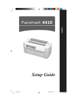
The Pacemark 3410 is a high speed, dot matrix printer, which utilizes a 9 pin printhead.
The printer is capable of emulating the IBM Proprinter or the Epson FX printers.
The Pacemark 3410 comes standard with both an RS232-C Serial Interface and a Centronics
Parallel Interface. Also standard is the bottom push tractor feed unit.
Pacemark 3410 Service Handbook
1-1
Specifications
1.2
1.2.01
PHYSICAL SPECIFICATIONS
Printer Dimensions
NOTE:
Dimensions include the bottom feed unit.
1.2.02
Width:
25.5 inches (54.0 centimeters)
Depth:
19 inches (48.3 centimeters)
Height:
15 inches (20.3 centimeters)
Printer Weight
63 pounds (25.4 kilograms)
United Parcel Service (UPS) shippable
1.3
1.3.01
POWER REQUIREMENTS
Input Power
Input Voltage
120 VAC +5.5%, -15%
220/240 +10%, -10%
Frequency
50/60 hz. +/-2%
1.3.02
Power Consumption
Operating:
75 W
Idle:
30 W
Specifications
1-2
Pacemark 3410 Service Handbook
1.4
1.4.01
ENVIRONMENTAL CONDITIONS
Acoustic Rating
58.5 dBa
1.4.02
Altitude
10,000 feet (3,048 meters)
1.4.03
Ambient Temperature and Relative Humidity
In Operation
41 to to 95 degrees Fahrenheit (5 to 35 degrees Celsius)
@ 20% - 80% Relative Humidity
In Storage
14 to to 122 degrees Fahrenheit (-10 to 50 degrees Celsius)
@ 5% - 95% Relative Humidity
1.5
1.5.01
AGENCY APPROVALS
Listings
North America
FCC Class B
UL 478 (Office Machines and Business Equipment)
CSA 22.2 (220)
Pacemark 3410 Service Handbook
1-3
Specifications
1.6
1.6.01
OPERATIONAL SPECIFICATIONS
Character Matrix Sizes
Print Mode
Near Letter Quality
Utility
High Speed Draft
1.6.02
Horizontal
24
12
9
Vertical
17
9
9
Characters Per Line
136 Characters @ 10 cpi
163 Characters @ 12 cpi
204 Characters @ 15 cpi
233 Characters @ 17.1 cpi
272 Characters @ 20 cpi
1.6.03
Character Pitches
10, 12, 15, 17.1, 20
1.6.04
Character Sets
Standard ASCII
Epson Character Set I
Epson Character Set II
IBM Character Set I
IBM Character Set II
IBM ALL (Proprinter) Character Set
Foreign Language Substitution (International Characters)
Line Graphics
Code Pages: 850, 863
Specifications
1-4
Pacemark 3410 Service Handbook
1.6.05
Emulations
NOTE:
The Plug-in Chip Set for Microline/Pacemark Emulation is installed by a technician.
Resident
Epson FX-1050
IBM Proprinter III
Optional Plug-in Chip Set
Microline/Pacemark
1.6.06
Fonts
Standard
Near Letter Quality
Courier
Gothic
Proportional
Draft
Utility
High Speed Draft
Custom Characters
Barcode
Code 128 (ABC)
Code 3 of 9
EAN 8
EAN 13
Interleaved 2 of 5
POSTNET
UPC-A
UPC-E
Pacemark 3410 Service Handbook
1-5
Specifications
1.6.07
Front Panel Switches
Select
Paper Park
Menu Mode
Pitch Selection
Line Feed
Print Quality Selection
Form Feed
Tear
Top of Form
1.6.08
Micro Feed Up / Down
Graphics Resolution
Maximum: 240 x 216 dots per inch (dpi)
1.6.09
Interface Methods
Standard
Centronics Parallel Interface
RS232-C Serial Interface (19.2 KB)
Optional
Twin-ax or Co-ax
Available from a third party vendor. Call 1-800-OKIDATA [1-800-654-3282] for more
information.
1.6.10
Line Feed Increments
1/6" (Selected through the Menu)
1/8" (Selected through the Menu)
n/72"
n/144"
n/216"
1.6.11
Line Feed Time
10.0 Inches Per Second (IPS) slew rate (when Printhead Gap Lever is set at 1
or 2)
6 IPS slew rate (when Printhead Gap Lever is set at 3 or 4)
5 IPS slew rate (when Printhead Gap Lever is set at 5 through 9)
Specifications
1-6
Pacemark 3410 Service Handbook
1.6.12
Menu Mode
Print: Prints the entire menu.
Group: Selects Group Function
Item: Selects Item
1.6.13
Set:
Selects Item Value
Exit:
Exits Menu Mode, Enters Select
Paper Feed Methods
Built-in Push Tractor (Bottom)
Built-in Push Tractor (Rear)
Friction Feed (Top)
Bottom Push Tractor Feed Unit
Optional Pull Tractor (Bottom / Rear)
Optional Cut Sheet Feeders (Single and Dual Bin)
1.6.14
Paper Feed Paths
Bottom Feed
Rear Feed
Top Feed
Special Features
Paper Park
Automatic Paper Loading
Forms Tear Off
1.6.15
Paper Loading
Auto Bail Arm for Auto Loading
1.6.16
Paper Out Detection
Distance from end of paper
Rear Feed:
2.30 inches (58.42 mm)
Bottom Feed:
.94 inches (23.88 mm)
Cut Sheet:
.93 inches (23.62 mm)
Pacemark 3410 Service Handbook
1-7
Specifications
1.6.17
Paper Tear Capabilities
Form Tear-Zero Tear
Metal Tear Bar
1.6.18
Print Method
Printhead Type
General Information
Impact, Dot Matrix
Staggered, 9 pin, stored energy printhead
0.36 mm diameter pins
Installed by Service Technician
The Printhead Gap Adjustment must be performed when the printhead is replaced.
Overheat Protection
When the printhead temperature reaches 115 degrees Celsius, the printer stops bi-directional
printing. Uni-directional printing begins.
If the temperature continues to rise (125° Celsius), printing stops.
Printing will resume when the printhead temperature drops below 115 degrees Celsius.
1.6.19
Print Modes
Near Letter Quality (NLQ)
Utility
High Speed Draft
1.6.20
Print Speeds
Pitch
10 cpi
12 cpi
15 cpi
17.1 cpi
20 cpi
High Speed Draft
550 cps
550 cps
550 cps
550 cps
550 cps
Utility
417 cps
417 cps
417 cps
417 cps
417 cps
Near Letter Quality
104 cps
104 cps
104 cps
104 cps
104 cps
cpi - Characters Per Inch
cps - Characters Per Second
Specifications
1-8
Pacemark 3410 Service Handbook
1.7
1.7.01
PAPER SPECIFICATIONS
Types
Card Stock
Weight:
120 lbs. (450 g/m2)
Maximum
Width:
5 to 14 inches (12.7 to 35.6 centimeters)
Length:
3 to 17 inches (7.62 to 43.18 centimeters)
Thickness:
.02 inches (0.5 millimeters)
Paper Feed Path:
Bottom
Head Gap
Lever Setting:
8-9
Continuous Form
Weight:
Single Part
12 - 24 lb. (45 to 90 g/m2)
Multi-Part,
Carbonless
9 - 11 lb. (35 to 40 g/m2)
Multi-Part,
Interleaf
Paper
Carbon
10 - 12 lb. (38 to 45 g/m2)
9 lb. (35 g/m2)
Width:
3 to 16 inches (76.2 to 406.4 millimeters)
Length:
3 to 17 inches (7.62 to 43.18 centimeters)
Thickness:
0.014 inches (0.36 millimeters)
0.02 inches (0.5 millimeters)
Paper Feed Path:
Rear or Bottom
Head Gap
Lever Setting:
1
Single Part
12 - 15 lb. (45 to 56 g/m2)
1-2
Single Part
20 - 24 lb. (75 to 90 g/m2)
2-3
Two Part
3-4
Three Part
5
Four Part
6
Five Part
7
Six Part
Pacemark 3410 Service Handbook
1-9
Rear Feed
Bottom Feed
Specifications
Cut Sheet
Weight:
12 to 24 lbs. (45 to 90 g/m2)
Width:
7.2 to 14.3 inches (18.3 to 36.3 centimeters)
Length:
3 to 17 inches (7.62 to 43.18 centimeters)
Thickness:
0.014 inches (0.325 millimeters)
Maximum
Paper Feed Path:
Top
Head Gap
Lever Setting:
1
12 - 15 lb. (45 to 56 g/m2)
1-2
20 - 24 lb. (75 to 90 g/m2)
Envelopes
Weight:
24 lbs. (90 g/m2)
Maximum
Size:
Single Feed
Minimum:
6.5 x 3.6 inches (16.5 x 9.1 centimeters)
Maximum:
9.5 x 4.1 inches (24.1 x 10.4 centimeters)
Continuous
Non-overlap type
Thickness:
.014 inches (.325 millimeters)
Paper Feed Path:
Bottom
Head Gap
Lever Setting:
5-9
Specifications
1 - 10
Maximum
Pacemark 3410 Service Handbook
Labels
Weight:
N/A
Width:
3 to 16 inches (7.62 to 40.64 centimeters)
Length:
3 to 17 inches (7.62 to 43.18 centimeters)
Thickness:
.011 inches (0.28 mm)
Paper Feed Path:
Bottom
Head Gap
Lever Setting:
3-4
Maximum (including backing)
Transparency
NOTE:
Roller marks may mar the transparency under high temperature / high humidity
conditions.
Weight:
12 to 24 lbs. (45 to 90 g/m2)
Width:
7.2 to 14.3 inches (18.3 to 36.3 centimeters)
Length:
3 to 17 inches (7.62 to 43.18 centimeters)
Thickness:
0.14 inches (0.36 millimeters)
Paper Feed Path:
Top
Head Gap
Lever Setting:
1
12 - 15 lb.
1-2
20 - 24 lb.
Pacemark 3410 Service Handbook
1 - 11
Specifications
1.7.02
Length
NOTE:
The recommended length is specific to paper type.
Rear Feed
Minimum
3 inches (7.62 centimeters)
Maximum
17 inches (43.18 centimeters)
Bottom Feed
Minimum
3 inches (7.62 centimeters)
Maximum
17 inches (43.18 centimeters)
Top Feed
Specifications
Minimum
3 inches (7.62 centimeters)
Maximum
17 inches (43.18 centimeters)
1 - 12
Pacemark 3410 Service Handbook
1.7.03
Number of Copies
Original + 5 Interleaf
Original + 7 Carbonless
Original + 3 Cut Sheet (top edge must be glued tight)
1.7.04
Thickness
0.014 inches / 0.36 mm Maximum Thickness, Rear Feed
0.020 inches / 0.50 mm Maximum Thickness, Bottom Feed
1.7.05
Weight
NOTE:
The recommended weight is specific to paper type.
1.7.06
Minimum:
9 lb. (35 g/m2)
Maximum:
24 lb. (90 g/m2)
Width
NOTE:
The recommended width is specific to paper type.
Minimum:
3 inches
Maximum:
16 inches
Pacemark 3410 Service Handbook
1 - 13
Specifications
1.8
1.8.01
MEMORY SPECIFICATIONS
EEPROM
Internal Control, Menu = 256 bits
1.8.02
RAM
Total RAM = 64 Kbytes
Print Buffer = 28 Kbytes
DLL Buffer = 0 to 31 Kbytes
1.8.03
ROM
Resident: Program ROM = 256 Kbytes
1.9
1.9.01
CONSUMABLES
Ribbon
Black Cartridge
Type: Nylon Fabric
Ribbon Life: Approximately 7.5 million characters
Specifications
1 - 14
Pacemark 3410 Service Handbook
1.10
OPTIONS
1.10.01
Cut Sheet Feeders
CSF 3001 Single Bin
and
CSF 3002 Dual Bin
14 inches wide
User installable
Sheet Capacity
170 sheets of 16 lb.
100 sheets 24 lb.
Paper Width
7.2 to 8.5 inches (18.3 to 21.6 centimeters)
Paper Length
10.1 to 14 inches (25.7 to 35.6 centimeters)
1.10.02
Pull Tractor with Acoustic Cover
Use with bottom feed for continuous forms, labels, and / or invoices.
1.10.03
Microline/Pacemark Emulation Chip Set
Technician installable
1.10.04
Printer Stands
Available through a Third Party Vendor.
For more information, please call
800-749-2258 (Pacemark ONLY)
800-827-2672 (all printers)
1.10.05
Twin-ax / Co-ax
Available through a Third Party Vendor.
For more information, please call 508-777-7957.
Pacemark 3410 Service Handbook
1 - 15
Specifications
1.11
RELIABILITY
1.11.01
Mean Time Before Failure (MTBF)
Approximately 8,000 hours @ 25% Duty Cycle, 35% Page Density
Approximately 2,000 hours @ 100% Duty Cycle
1.11.02
Mean Time To Repair (MTTR)
Approximately 15 minutes @ major sub-assembly level
1.11.03
Printer Life
Approximately 16,000 Hours @ 25% Duty Cycle, 35% Page Density
1.11.04
Printhead Life
Approximately 200,000,000 characters (average)
@ 10 cpi Draft Mode @ 25% Duty Cycle, 35% Page Density
1.11.05
Ribbon Life
Approximately 7.5 million characters
1.11.06
Warranty (Limited)
One year parts, labor, printhead
1.11.07
Service
90 days, on-site
Specifications
1 - 16
Pacemark 3410 Service Handbook
SECTION TWO
PRINCIPLES OF OPERATION
2.1
ELECTRICAL OPERATION
2.1.01
General Information
The main logic board consists of the microprocessor, its peripheral LSI circuits, ROM, DRAM
and the drive circuits. The voltages for the main logic board are supplied by the power supply
unit. The voltages for the various electrical components (motors, sensors, etc.) are distributed
from the main logic board.
Pacemark 3410
2-1
Principles of Operation
2.1.02
Microprocessor (MPU) and Peripheral Circuits
Microprocessor
Q3: M67X640V1
The MicroProcessor Unit (MPU) is the nucleus of the control circuit. Various peripheral
circuits operate under program control of this microprocessor. The MPU (Q3) controls all
aspects of printer operation.
Program ROM for the MPU
Q4: 27C202K
This 2Mbit Read Only Memory (ROM) contains the control program for the printer. The
MPU operates under program control.
This ROM also stores the resident character fonts.
DRAM
Q10 and Q11
The Dynamic Random Access Memory (RAM) chips, each consisting of 64 K x 4 bits, are
used as the Command Buffer, Receive Buffer and Print Buffer.
The total buffer size is 64 K x 8 bits. The RAM speed is 120 ns.
EEPROM
Q14: 93C06N
This 256-bit serial Electrically Erasable and Programmable Read Only Memory (EEPROM)
stores the menu data and initial settings for the LSI circuits.
Principles of Operation
2-2
Pacemark 3410
Interface/Motor Control LSI
Q5: B562 13497
This LSI controls the following functions listed below.
Space Motor Enable / Speed Control
To obtain the carriage speed instructed by the microprocessor, Q5 uses the signals
SP - Phase A and SP - Phase B, derived from space motor movement to generate the
pulse width timing and overdrive time.
Line Feed Motor Phasing Control
To turn the line feed motor in the proper direction, this LSI sends motor drive signals
(properly phased) to the line feed driver (TRA4).
Bail Motor Phasing Control
To turn the bail motor in the proper direction, this LSI sends motor drive signals
(properly phased) to the bail driver (TRA3).
Dot ON Timing signal generation
Q5 uses the signals SP - Phase A and SP - Phase B, derived from space motor
movement, to produce the signal IPT. This signal (IPT) is used to enable the print wires
at the desired carriage position.
Printhead / Bottom Tractor Feed Control LSI
Q2: B563 12597
This LSI enables the printhead drivers and is the interface between the bottom tractor feed unit
(BTFD PCB) and the MPU.
The functions of this LSI are described below.
Printhead Drive Control
Printhead drive correction modifies the drive time under the following circumstances:
Drive time correction for drive voltage fluctuations
Drive time correction for head gap setting.
Bottom tractor feed unit control
Pacemark 3410
2-3
Principles of Operation
2.1.03
Initialization
The printer is initialized whenever it is powered ON or when the I-PRIME signal is received
from the host at the parallel interface.
The initialization process is performed as listed below.
1. The reset circuit sends the RST-P signal to the MPU and LSIs.
2. ROM program execution starts with the mode setting of Q2 and Q5.
3. ROM and RAM are checked for errors.
4. RAM is initialized.
5. Bail and carriage homing is performed.
6. The interface signals (output level of ACK, BUSY, etc.) are set.
7. The SELECT lamp is turned ON.
8. The printer signals the host computer that it is ready to receive data.
Principles of Operation
2-4
Pacemark 3410
Block Diagram
2-A.pcx
Pacemark 3410
2-5
Principles of Operation
2.1.04
Interface Control
The printer is capable of serial or parallel operation. The desired interface method is selected by
sliding the interface cover to expose the desired connector. When this is done, the interface
select switch is turned ON or OFF to inform the Interface/Motor Control LSI (Q5: B562 13497)
of the selected interface.
Parallel Interface
When the interface select switch is turned OFF, the parallel interface is selected and Q5 is in the
parallel interface mode.
The data from the interface is received through connector (CN-1) and Q5 latches this data in
sync with the STB signal.
The BUSY signal is turned ON as the data is processed. When processing is completed, the
BUSY signal is turned OFF and an ACK signal is sent to the host to request more data.
The BUSY signal is also turned ON when the printer is not able to receive data (the Print Buffer
is full, the printer is deselected or an error condition exists).
2-B.pcx
Principles of Operation
2-6
Pacemark 3410
RS232-C Serial Interface
When the interface select switch is turned ON, the serial interface is selected and Q5 is in the
serial interface mode.
The RS232-C interface signals (DSR, CTS, CD and RD) are converted to TTL levels by the line
receiver (Q13) and input to Q5 where the serial data is converted to parallel data.
The interface signals (DTR, RTS, SSD and TD) output from Q5 are converted from TTL levels
to RS232-C levels by the line driver (Q12) and sent to the serial interface connector.
2-C.pcx
Pacemark 3410
2-7
Principles of Operation
2.1.05
Printhead Drive Circuit
This circuit is used to drive the 9 print wires. The signals HD01 through HD09 from Q2 are
used to enable the individual wire drivers (TRA1 and TRA2). TRA1 drives Pins 1, 2, 6 and 7.
TRA2 drives Pins 3, 4, 8 and 9. TR7 drives Pin 5. The HD ON signal enables the drive circuit
when printing is desired. The head drive duration is determined by an RC integrating circuit
which modifies the HD ON pulsewidth. The pulsewidth of the HD ON signal varies with the
number of pins being driven. The drive time is increased as a greater number of pins are driven,
but decreased as less pins are to be driven. The drive time is also increased if the head gap lever
in placed in positions 3 through 9. The RC circuit is also used to compensate for the fluctuation
of drive voltage (+38vdc).
2.1.06
Spacing Drive Circuit
After receiving a spacing command from the MPU (Q3), the Interface/Motor Control LSI (Q5)
outputs the SPFWD signal to run the DC motor in the forward direction, or the SPRVS signal to
run the DC motor in the reverse direction. This is a fixed pulsewidth signal.
To control the motor speed, Q5 varies the pulse duty cycle according to feedback received from
the space motor. As the space motor rotates, the SPSP Board (inside the motor housing)
generates feedback pulse signals SPφA and SPφB. Q5 detects the edge pulses from these signals
and divides the frequency to output the IPT signal for use in printhead dot timing.
The space motor interlock switch (located at the left side of the shield plate) disables the space
motor drive signals whenever the printer cover is open.
Fuse F1 (3.5 amperes) protects the +38vdc space motor power circuit, should an overdrive
condition exist.
2-D.pcx
2-E.pcx
Principles of Operation
2-8
Pacemark 3410
2.1.07
Line Feed Circuit
Whenever it is in a stopped position, the line feed motor shaft is held stationary by +8vdc, which
is enabled by the LFCHOP Signal from Q2. The holding current is approximately 30 ma.
During a line feed operation, the line feed motor is driven by +38 vdc in accordance with the
LFOVDV signal. The signals LF - Phase 01 and LF - Phase 04 establish the proper phase
relationship for driving the motor. However, the line feed motor uses Phase 1 - 4.
2-F.pcx
Pacemark 3410
2-9
Principles of Operation
2.1.08
Alarm Circuits
Fault Alarm Circuit (in Power Supply Unit)
This protective circuit turns off the power supply when a fault occurs in the printhead, line feed,
or bail motor drive circuits, thus preventing secondary component failure.
To accomplish this, the circuit monitors the overdrive signal of each drive circuit. If the
duration of any drive circuit exceeds a predetermined length of time, the appropriate signal
(EVN COM, ODD COM, LF COM or BM COM) will be sent to the fault alarm circuit. The
fault alarm circuit generates the ALM signal which causes the power supply to turn all DC
power OFF.
Printhead Overheat Alarm Circuit
In order to protect the printhead coils, this circuit monitors the printhead temperature by using a
thermistor contained in the printhead. The CPU senses this circuit every time a line is printed.
When printing, the printhead temperature will increase. If the head temperature reaches
approximately 115° Celsius, a head overheat ALARM 1 is generated. When ALARM 1 is
detected by the MPU, the printer will begin unidirectional printing. If the printhead temperature
increases to 125° Celsius, ALARM 2 is generated and printing is halted until the head
temperature decreases. When the head temperature returns below the ALARM 1 threshold,
printing is resumed.
Cover Open Alarm Circuit
When the front access cover is opened, the CVOPEN-N signal is sent to the MPU from the
cover interlock microswitch. The MPU will halt printing immediately and light the ALARM
Lamp.
2.1.09
Paper End Detection Circuit
NOTE:
Paper End is also known as paper out
Whenever the release lever is in the Tractor (Continuous) Feed position, paper end is detected
by the microswitch on the push tractor (rear feed) or the paper end sensor on the sensor board
(bottom feed).
Whenever the release lever is in the Friction (Sheet) Feed position, Paper End is detected by a
photosensor (top feed) located in the paper pressure guide.
When the printer detects an out of paper condition, the PEN (Paper End) signal goes low, the
printing is stopped and the ALARM LAMP is turned ON.
Principles of Operation
2 - 10
Pacemark 3410
2.1.10
Power Supply
This switching power supply converts the AC input voltage to +5vdc, +/-8vdc and +38 vdc for
use throughout the printer.
Voltage / Signal Table
Voltage/Signal
+5 vdc
+8 vdc
-8 vdc
+38 vdc
POW ALM
ALM
Purpose
IC logic Levels - LED Drive Voltage
Serial Interface logic Levels - Line Feed Motor Locking Voltage
Serial Interface logic Levels
Printhead, Space Motor, Line Feed Motor, Bail Motor Drive Voltage
Output from the Power Supply in the event of an abnormal temperature rise in the
power supply unit or an overcurrent condition of the +38 vdc. The main logic board
suppresses this condition by temporarily suspending printing. If the condition does
not change, the main logic board will enable the FAN ALARM.
Refer to Section 4 - Failure Analysis
Input from the main logic board upon detection of an overdrive condition in the
printhead, line feed motor or bail motor drive circuits. Upon detecting this signal, the
power supply disables the +38 vdc output.
2-J.pcx
Pacemark 3410
2 - 11
Principles of Operation
2.2
MECHANICAL OPERATION
2.2.01
Printhead Mechanism
The printer uses a highly efficient stored energy type printhead. Power is not consumed until the
printwires are activated, thereby extending the printhead life to approximately 200 million
characters.
The printhead uses 9 printwires in two columns. Each wire is welded to an armature. Behind
this armature is a spacer ring.
Each of the 9 printwire armatures has a permanent magnet behind it. The magnets attract the
armatures, pulling the printwires into the wire guide, thus keeping the wires inside the printhead.
A coil is wrapped around each of the permanent magnets.
When a dot is to be printed, current is passed through the appropriate coil. This creates an
electromagnetic field which counters the magnetic field of the permanent magnet. The armature
can then spring forward and the print wire (which is attached to the armature) strikes the ribbon
and imprints a dot on the paper.
When current is removed from the coil, the magnetic field of the permanent magnet attracts the
armature, causing the printwire to retract into the wire guide once again.
The printhead consists of the parts listed below.
Wire Guide
Print Wires
Armature Assembly
Spacer
Permanent Magnet Assembly
Thermistor: used to monitor the printhead temperature
Printed Circuit board with Coils
Head Gap Adjusting
The head gap adjusting mechanism modifies the gap between the platen and printhead. This is
accomplished by moving the adjusting lever on the right side of the printer mechanism. When
the lever is moved, the carriage shaft rotates. Since the carriage shaft is attached to the printer
mechanism through eccentric collars, turning the carriage shaft, changes the distance between
the platen and the printhead.
Principles of Operation
2 - 12
Pacemark 3410
2-2.pcx
Wire Guide
Print Wire
Armature
Thermistor
Spacer Ring
Coil
Permanent Magnet
2-3.pcx
Pacemark 3410
2 - 13
Principles of Operation
2.2.02
Spacing Mechanism
Spacing is performed when the servo motor drives the carriage along the carriage shaft, parallel
to the platen.
The spacing mechanism consists of the following items.
DC (Servo) Motor
Idle Pulley
Carriage Shaft
Carriage Frame
Space Belt
Spacing Operation
The carriage containing the printhead moves parallel to the platen along the carriage shaft.
Power from the space motor is transferred via the space belt, which is attached to the bottom of
the carriage. The carriage is designed to move 1.6 inches when the servo motor performs one
rotation.
Carriage Shaft
Carriage Frame
Idle Pulley
Space Belt
DC (Servo) Motor
2-4.pcx
Principles of Operation
2 - 14
Pacemark 3410
2.2.03
Ribbon Drive Mechanism
The ribbon drive mechanism moves the ribbon in synchronization with the space motor
operation.
The ribbon drive mechanism consists of the items listed below.
Ribbon Drive Assembly
Ribbon Cartridge
Ribbon Cartridge
An endless ribbon with a single direction feed is used. Ink is supplied from an ink tank, which is
contained in the ribbon cartridge.
Ribbon Feed Operation
The rotation of the space motor is transmitted to the drive gear in the ribbon cartridge through
the ribbon feed gear assembly, thereby feeding the ink ribbon.
The feed direction of the ribbon is maintained by switching the rotational direction of the gears
in the ribbon drive assembly. This ensures unidirectional ribbon movement when bi-directional
printing is used.
Ribbon Cartridge
Ribbon Drive Assembly
2-5.pcx
Pacemark 3410
2 - 15
Principles of Operation
2.2.04
Paper Feed Mechanism
Paper feeding is performed by turning the platen and the tractors, which are driven by the line
feed pulse motor.
The paper feed mechanism consists of the items listed below.
Line Feed (Pulse) Motor with gears
Idle Gear
Change Spring
Change Gear
Platen
Push Tractor Assembly
Bottom Tractor Feed Unit
Paper Pressure Guide
Friction (Sheet) Feed
When the release lever is set to the
SHEET FEED position, the change gear is
disengaged from the tractor gear. At the
same time, the release lever applies
pressure to push the pressure rollers
against the platen, allowing paper to be
fed.
Paper Pressure Guide
Line Feed Motor
Platen
A photosensor located in the paper
pressure guide detects PAPER END.
2-7.pcx
Tractor (Continuous) Feed
When the Release Lever is set to the
TRACTOR FEED position, the release
lever allows the reset spring to push the
change gear toward the tractor gear. At
the same time, the release lever pushes the
pressure rollers away from the platen,
allowing paper to be fed by the tractors.
Tractor Feed
Unit
Change Gear
Change
Spring
The microswitch on the push tractor (rear
feed) and the paper end sensor on the
sensor board (bottom feed) detect PAPER
END.
Idler Gear
2-8.pcx
Principles of Operation
2 - 16
Pacemark 3410
2.2.05
Paper-End Detection Mechanism
Friction Feed (Cut-Sheet) Paper-End
When the Release Lever is in the SHEET
FEED Position, the photosensor located in
the Paper Pressure Guide is active. If sheet
paper is installed, the paper is detected by
the sensor and the sensor is turned ON.
When the printer is out of sheet paper, the
sensor is turned OFF indicating a
paper-end condition.
Continuous (Bottom) Feed Paper-End
2-7.pcx
(Also used with Bottom Tractor Feed Unit)
When the Release Lever is in the
TRACTOR FEED Position, the switch on
the left Push Tractor and the Paper-End
sensor on the sensor board are active. If
paper is detected by either of these sensors,
paper-end is inhibited.
When bottom feed paper is installed, it
moves the bottom paper-end lever to turn the
sensor ON. When a paper out condition
exists, the lever blocks the sensor, indicating
a paper-end condition.
Continuous (Rear) Feed Paper-End
2-13.pcx
When the Release Lever is in the
TRACTOR FEED Position, the switch on
the left Push Tractor and the Paper-End
sensor on the sensor board are active. If
paper is detected by either of these sensors,
Paper-End is inhibited.
When rear feed paper is installed, pressure
is placed on the microswitch, located in the
left push tractor. Since the switch is turned
ON, paper is detected.
2-12.pcx
Pacemark 3410
2 - 17
Principles of Operation
2.2.06
Automatic Paper Loading
Automatic Paper Loading is used to consistently set the print start position when using cut-sheet
or continuous sheet paper. The autoloading procedures for each type of paper follow.
Cut-Sheet Paper
1. Push the paper release lever to the cut-sheet position.
2. Insert the paper from behind the platen.
3. Press the FORM FEED switch.
4. The paper bail will automatically open.
5. The line feed operation will load the paper.
6. The paper bail will automatically close.
NOTE:
If the paper does not move, the Auto-Load motion becomes invalid and is treated like an
ordinary paper-end condition.
Continuous Sheet (Rear Feed) SASF
1. Push the paper release lever to the continuous sheet side (front of printer).
2. Insert the paper into the push tractor. The white guide line on the left tractor MUST
be visible.
3. Press the FORM FEED switch.
4. The paper bail will automatically open.
5. The line feed operation will load the paper.
6. The paper bail will automatically close.
NOTE:
If the paper does not move, the auto-load motion becomes invalid and is treated like an
ordinary paper-end condition.
Principles of Operation
2 - 18
Pacemark 3410
2.2.07
Paper Park Feature
Occasionally, the user will want to print on cut-sheet paper, and continuous feed paper is loaded
in the printer. Rather than unloading the continuous feed paper, the operator can use the paper
park feature. Paper Park retracts the continuous feed paper until a paper-end condition exists or
until 14 inches of paper has been retracted. The continuous feed paper remains on the push
tractor (or bottom tractor feed unit), but out of the printing path. This allows cut-sheet paper to
be loaded. Once the cut-sheet printing is complete, the continuous feed paper is reloaded.
CAUTION:
Do not attempt to PARK labels or more than one sheet of paper
Pacemark 3410
2 - 19
Principles of Operation
This page was intentionally left blank.
Principles of Operation
2 - 20
Pacemark 3410
SECTION THREE
MAINTENANCE
3.1
OVERVIEW
3.1.01
General Information
This section lists the parts replacement, adjustment, cleaning, lubrication, and shipping
procedures.
Disassembly should not be performed unless absolutely necessary. NEVER perform
disassembly on a malfunctioning unit until you have followed the failure analysis procedures in
Section Four of this Service Handbook.
Follow the procedures listed in Adjustments and Service Settings. Adjustments may be required
when either consumables or parts are replaced. Failure to perform these procedures could result
in unnecessary service calls.
Cleaning procedures must be performed correctly if high print quality is to be achieved.
Pacemark 3410 Service Handbook
3-1
Maintenance
3.1.02
Maintenance Items
The following items are required to service the unit.
#1 Phillips Screwdriver (with magnetic tip, 10 inch shaft)
#2 Phillips Screwdriver (with magnetic tip, 6 inch shaft)
#3 Phillips Screwdriver (with magnetic tip)
Straight-slot Screwdriver (1/4 inch)
Needle Nose Pliers (4 inch)
Diagonal Cutters
Tension Gauge (capable of measuring 1 pound of pressure)
7 mm open-ended wrench
Ruler (capable of measuring 1/16 inch increments)
3/32 inch socket with driver
Feeler Gauge
Paper Clip (used for Microswitch 2 modification)
Digital Multimeter
Shop Vacuum
Cloth (soft and lint-free)
All-Purpose Cleaner
Machine Oil
Graphite Based Lubricant
Contact Kleen (Okidata P/N 51802301)
Maintenance
3-2
Pacemark 3410 Service Handbook
3.1.03
Maintenance Precautions
1. Do not disassemble the unit if it is operating normally.
2. Before starting disassembly and assembly, always power OFF the unit and detach the
AC power cord.
3. Detach the interface cable, if installed.
4. Do not remove parts unnecessarily. Try to keep disassembly to a minimum.
5. Use the recommended maintenance tools.
6. When disassembling, follow the listed sequence. Failure to follow the correct
sequence may result in damaged parts.
7. Since screws, collars and other small parts are easily lost, they should be temporarily
attached to the original positions.
8. When handling circuit boards use extreme care. Integrated circuits (microprocessors,
ROM, and RAM) can be destroyed by static electricity.
9. Do not place printed circuit boards directly on conductive surfaces.
10. Follow the recommended procedures when replacing assemblies and units.
11. Perform the printhead gap adjustment when any of the items listed below occur.
•
Print Quality is darker on one side of the document.
•
Parts / Assemblies are replaced.
Printhead (3.2.01)
Platen Assembly (3.2.16)
Carriage Shaft (3.2.22)
Pacemark 3410 Service Handbook
3-3
Maintenance
This page was intentionally left blank.
Maintenance
3-4
Pacemark 3410 Service Handbook
3.2
DISASSEMBLY/ASSEMBLY PROCEDURES
General Information
This section contains the printer disassembly procedures. Only the removal procedures are
explained here. Reverse the procedure for the installation.
At the bottom of each procedure is a listing of the parts covered in that procedure. The Okidata
part number, item description, comment (RSPL, Option, Consumable) and cross-reference to
Appendix B is provided for each part. Items included in the Recommended Spare Parts List are
indicated by the acronym RSPL. N/A will appear where a part number is not available.
Part
Number
Item
Description
Comment
Appendix B
Reference
This Service Handbook lists the disassembly procedures for major components of the unit.
Okidata DOES NOT recommend disassembling a unit which is operating normally. If you
decide to perform disassembly during this training, Okidata recommends that you perform only
the disassembly procedures for RSPL items. All other procedures are provided to assist you in
identifying parts. It is not likely that you will perform these procedures while servicing the unit.
Be sure to read all notes, cautions, and warnings, as they contain important information
regarding disassembly / assembly.
Pacemark 3410 Service Handbook
3-5
Maintenance
3.2.01
Printhead (with Preliminary Items)
WARNING:
The printhead will be HOT immediately after printing.
1. Open the printer access cover (1).
2. Remove the ribbon cartridge (2).
3. Set the head gap adjusting lever (3) to the range ’9’ position.
4. Lift and remove the ribbon guide (4) from the two posts.
5. Remove the two printhead mounting screws (5).
6. Disconnect the printhead (6) from the connector by lifting.
NOTES:
Installation
Push the printhead towards the platen (in the direction of Arrow A).
Perform the printhead gap adjustment. Refer to Section 3.3
P/N 50215701
Cover: Access
RSPL
B.2.02
P/N 50090301
Printhead: Assembly
RSPL
B.2.03
P/N 52105801
Ribbon Cartridge
Consumable
B.2.03, B.2.12
P/N 56609701
Cord: AC (120V)
RSPL
B.2.03
P/N 56624101
Cord: AC (220V) (ML) Right Angle
Option
B.2.03
P/N 53062601
Guide: Ribbon Assembly
RSPL
B.2.05
Maintenance
3-6
Pacemark 3410 Service Handbook
A
4
5
2
6
3
1
3-2-01.pcx
Pacemark 3410 Service Handbook
3-7
Maintenance
3.2.02
Ribbon Protector Assembly
1. Open the printer access cover.
2. Remove the ribbon cartridge.
3. Set the head gap adjusting lever to the range ’9’ position.
4. Lift and remove the ribbon guide from the two posts.
5. Remove the two mounting screws (1) and detach the ribbon protector (2) by lifting.
P/N 50316701
Screw: Ribbon Protector (Post)
RSPL
B.2.05
P/N 53062701
Protector: Ribbon Assembly
RSPL
B.2.05
Maintenance
3-8
Pacemark 3410 Service Handbook
1
2
3-2-02.pcx
Pacemark 3410 Service Handbook
3-9
Maintenance
3.2.03
Upper Cover Assembly
1. Detach the platen knob (1).
2. Pull the release lever (2) toward the front of the printer.
3. Remove the two cover mounting screws (3), located at the rear of the printer.
4. Lift the sheet separator (4).
5. Open the bail arm (5).
6. Grasp the pull-up roller assembly (6), then lift and rotate it towards the back of the
printer.
7. Close the bail arm.
8. Lower the sheet separator.
9. Lift the upper cover assembly (7) at the rear of printer. Rotate the assembly towards
the front of the printer, disengaging the cover from the four claws (8) at the front of
the printer.
CAUTION:
When installing the upper cover assembly, move the bail arm lever towards the back of
the printer and move the release lever towards the front of the printer. Then, check that
the paper bail moves properly.
P/N 50212431
Cover: Middle (PM3410)
RSPL
B.2.02
P/N 50215801
Cover: Rear (Assembly)
RSPL
B.2.02
P/N 50215901
Pull-Up Roller Assembly
RSPL
B.2.02
P/N 50215901
Pull-Up Roller Assembly
RSPL
B.2.03
P/N 53478601
Knob: Platen
RSPL
B.2.03
P/N 50910505
Spring: Cover Open
RSPL
B.2.04
Maintenance
3 - 10
Pacemark 3410 Service Handbook
1
3
7
8
6
2
4
5
3-2-03.pcx
Pacemark 3410 Service Handbook
3 - 11
Maintenance
3.2.04
Operator Panel
1. Remove the upper cover assembly (3.2.03)
2. Disconnect the operator panel cable (1) from CN10 (2) on the control board.
3. Remove the two mounting screws (3).
4. Detach the operator panel assembly by moving it upward, and then pulling toward
the front of the printer, detaching the four claws.
5. Release the ten claws.
6. Detach the operator panel (4) from the operator panel holder (5).
P/N 53553401
Panel: Operator (PM3410)
RSPL
B.2.04
P/N 55061401
PCB: OPML Operation Panel
RSPL
B.2.04
P/N 56628402
Cable: Op Panel (PM3410)
RSPL
B.2.04
Maintenance
3 - 12
Pacemark 3410 Service Handbook
2
1
1
3
3-2-04.pcx
5
4
Pacemark 3410 Service Handbook
3 - 13
Maintenance
3.2.05
Interface Connector Board
NOTE:
To allow easier access to the mounting screw and cables, configure the interface
connector board to use the serial interface connector.
1. Remove the upper cover assembly (3.2.03).
2. Disconnect connectors CN101 (1), CN102 (2), and CN103 (3).
3. Remove the two mounting screws (4) and detach the interface connector board (5) by
lifting.
NOTE:
After assembly, configure the interface connector board for the desired type of interface.
P/N 55061711
Maintenance
PCB: HKTY Interface Connector Assembly
3 - 14
RSPL
B.2.03
Pacemark 3410 Service Handbook
4
1
2
5
3
3-2-05.pcx
Pacemark 3410 Service Handbook
3 - 15
Maintenance
3.2.06
Main Logic (CBNP) Board
1. Remove the upper cover assembly. (3.2.03)
2. Remove the ribbon cartridge.
3. Release the lock of connector CN10 (1) and detach the operator panel cable (2).
4. Remove the five shield cover mounting screws (3).
5. While slightly lifting the shield cover (4), detach connectors CN11 (5) and CN12 (6)
from the main logic board.
6. Remove the shield cover.
7. Detach the connectors CN1, CN2, CN3, CN5, CN6, CN7, CN8, and CN9 (7).
8. Loosen the mounting screw (8).
9. Remove the main logic board (9).
CAUTION:
When assembling the printer, follow these instructions.
1. Do not allow cables to get caught under the main logic board.
2. Insert the main logic board into the groove in the base tray (10).
3. Fit the main logic board into the groove (11) in the shield cover, then secure the
shield cover.
P/N 55061611
PCB: CPNB Main Logic (w/o ROM)
RSPL
B.2.03
P/N 55934601
IC: EEPROM NM93C06N-NW
RSPL
B.2.03
P/N 56212601
Switch: Interlock (Assy)
RSPL
B.2.04
Maintenance
3 - 16
Pacemark 3410 Service Handbook
3
1
1
2
7
11
4
5
9
8 6
10
3-2-06.pcx
Pacemark 3410 Service Handbook
3 - 17
Maintenance
3.2.07
Printer Mechanism
1. Remove the main logic board (3.2.06).
2. Detach connectors CN102 (1) and CN103 (2) from the interface connector board (3).
3. Remove the three mounting screws (4) at the rear of the printer mechanism (5).
4. Remove the three mounting screws and brackets (6). There are two on the left side of
the printer mechanism and one on the right side.
CAUTION:
Do not grasp the ribbon cartridge bracket, paper chute, or the guide shaft of the sheet
feeder assembly when lifting the printer during the next step.
5. Grasp the printer mechanism near the line feed motor (Position A).
6. While holding at position A, also grasp the printer mechanism (Position B).
CAUTION:
DO NOT GRASP THE RIBBON CARTRIDGE BRACKET -- IT WILL BEND.
7. Lift and remove the printer mechanism.
NOTE:
When assembling the printer, do not allow cables to get caught under the printer
mechanism.
P/N 56614101
Cord: Power Connection (9 Pin)
RSPL
B.2.03
P/N 56614801
Cord: Power Connection (13 Pin)
RSPL
B.2.03
P/N 56614901
Cable: I/F (Internal) [I/F-Main Brd 50 Pin]
Maintenance
3 - 18
RSPL
B.2.03
Pacemark 3410 Service Handbook
4
6
A
1
2
5
6
B
6
3
3-2-07.pcx
Pacemark 3410 Service Handbook
3 - 19
Maintenance
3.2.08
Power Supply Unit
1. Remove the printer mechanism (3.2.07).
2. Disconnect the two cables (1) from the left side of the power supply unit (2).
3. Remove the four power supply mounting screws (3).
4. To remove the power supply unit:
Rotate the left side of the power supply unit towards the front of the printer.
Lift the power supply unit to disengage the power switch (4), AC receptacle (5)
and the tabs (6).
CAUTION:
Be careful not to damage the cables with the power supply unit mounting bracket (7).
This bracket is located at the left/rear of the power supply unit.
P/N 56406302
Power Supply Assembly (220/240 V)
Option
B.2.03
P/N 56411201
Power Supply Assembly (120 V)
RSPL
B.2.03
Maintenance
3 - 20
Pacemark 3410 Service Handbook
6
5
4
3
7
2
1
3-2-08.pcx
Pacemark 3410 Service Handbook
3 - 21
Maintenance
3.2.09
Printer Unit
1. Detach the DIN connector (1).
2. Lift the printer unit (2) from the bottom tractor feed unit (3).
Maintenance
3 - 22
Pacemark 3410 Service Handbook
2
3
1
3-2-09.pcx
Pacemark 3410 Service Handbook
3 - 23
Maintenance
3.2.10
BTFD PCB
1. Remove the printer unit (3.2.09).
2. Disconnect the connectors CN1 (1) and CN2 (2) on the BTFD PCB (3).
3. Remove the two mounting screws (4).
4. Remove the BTFD PCB.
P/N 55066101
Maintenance
PCB: BTFD (BTF)
RSPL
3 - 24
B.2.08
Pacemark 3410 Service Handbook
4
1
2
3
3-2-10.pcx
Pacemark 3410 Service Handbook
3 - 25
Maintenance
3.2.11
Tension Spring
1. Remove the printer unit (3.2.09).
2. Raise the front door assembly (1).
3. Detach the tension spring (2) from the upper plate (3).
4. Detach the tension spring from the front door assembly.
P/N 50922001
Maintenance
Spring: (BTF)
RSPL
3 - 26
B.2.08
Pacemark 3410 Service Handbook
3
2
1
3-2-11.pcx
Pacemark 3410 Service Handbook
3 - 27
Maintenance
3.2.12
Bottom Push Mechanism and Front Door Assembly
1. Remove the printer unit (3.2.09).
2. Remove the tension spring (3.2.11).
3. Detach connector CN1 (1) on the BTFD PCB (2).
4. Remove the four screws (3).
5. Remove the bottom push mechanism (4).
6. Remove the front door assembly (5).
P/N 53063701
Maintenance
Door: Front (Assembly) (BTF)
3 - 28
RSPL
B.2.08
Pacemark 3410 Service Handbook
3
1
4
2
5
3-2-12.pcx
Pacemark 3410 Service Handbook
3 - 29
Maintenance
3.2.13
Drive Pulley and Belt
1. Remove the printer unit (3.2.09).
2. Remove the tension spring (3.2.11).
3. Remove the bottom push mechanism (3.2.12).
4. Loosen the two motor screws (1).
5. Push the motor (2) in the direction of Arrow A, to loosen the belt (3).
6. Remove the belt.
7. Pry open the claws in the center of the pulley, then remove the drive pulley (4) from
the tractor feed drive shaft (5).
NOTES:
The drive pulley has two parts. Disassembly of the drive pulley is not required during
this procedure.
Once the drive pulley has been removed, be sure that the tractor feed drive shaft is not
removed. If you remove the tractor feed drive shaft, the left or right tractors will lose
the synchronization between the pin feeds.
When assembling, perform the belt tension adjustment (3.3.02).
P/N 51226901
Pulley: Drive (BTF)
RSPL
B.2.08
P/N 51304501
Belt: Line Feed (BTF) Mini-Pitch [120 teeth]
RSPL
B.2.08
Maintenance
3 - 30
Pacemark 3410 Service Handbook
1
3
A
5
2
4
Pacemark 3410 Service Handbook
3-2-13.pcx
3 - 31
Maintenance
3.2.14
Tractor Assembly (BTF)
NOTE:
On each side frame, the tractor drive shaft passes through a plastic bushing. These
bushings should remain in the frame. However, if a bushing must be removed, press the
bushing’s claw which can be accessed from the inside of the side frame.
1. Remove the drive pulley (3.2.13).
2. Remove the tractor drive shaft (1) by sliding it to the right.
3. Rotate the tops of both the left (2) and right (3) tractor assemblies and the sheet guide
(not shown) in the direction of Arrow A.
4. Lift the left side of the drive roller (4) and remove the drive roller, tractor assemblies,
and sheet guide.
NOTES:
The sheet guide may be removed without disassembling the drive shaft.
When installing the tractor assemblies, take the following precautions:
Make sure that the tractors are synchronized by aligning the synchronization
marks (5).
The left tractor assembly must be positioned to the left of the metal tab.
P/N 50057401
Left Tractor Assembly
RSPL
B.2.08
P/N 50057501
Right Tractor Assembly
RSPL
B.2.08
P/N 51002201
Guide: Sheet (BTF)
RSPL
B.2.08
P/N 53340401
Roller: Drive (BTF)
RSPL
B.2.08
Maintenance
3 - 32
Pacemark 3410 Service Handbook
4
1
A
3
2
3-2-14.pcx
5
Pacemark 3410 Service Handbook
3 - 33
Maintenance
3.2.15
Line Feed Motor (BTF)
1. Remove the bottom push mechanism (3.2.12).
2. Remove the two screws (1).
3. Remove the line feed motor (2).
NOTE:
When installing the line feed motor, the harness should be oriented towards the top.
This line feed motor is used in two different places: the bottom push unit and the printer
unit.
P/N 56509401
Maintenance
Motor: Line Feed (BTF)
RSPL
3 - 34
B.2.08
Pacemark 3410 Service Handbook
2
1
3-2-15.pcx
Pacemark 3410 Service Handbook
3 - 35
Maintenance
3.2.16
Platen Assembly
1. Remove the printer mechanism (3.2.07).
2. Loosen the three 7 mm line feed motor mounting bolts (1).
3. Move the line feed motor (2) closer to the platen (3) and detach the line feed drive
belt (4).
4. Remove the E-ring, washer, spring and idle gear (5).
5. Remove the screw and detach the gear pulley, washer and bushing (6).
6. Remove the screw and detach the gear and bushing (7).
7. Push in the platen lever (8), lift the bail and remove the platen.
NOTE:
Perform the line feed belt tension adjustment after replacing the line feed drive belt.
Refer to Section 3.3
Perform the printhead gap adjustment after installing the platen. Refer to Section 3.3.
P/N 50054101
Platen: (Assembly)
RSPL
B.2.06
P/N 51214501
Gear: Platen "A"
RSPL
B.2.06
P/N 51226801
Pulley: Platen
RSPL
B.2.06
P/N 51304401
Belt: Mini Pitch (Line Feed)
RSPL
B.2.06
OLD
P/N 50910305
Maintenance
Spring: Idle Gear
3 - 36
Pacemark 3410 Service Handbook
8
3
5
7
1
2
3-2-16.pcx
4
6
Pacemark 3410 Service Handbook
3 - 37
Maintenance
3.2.17
Paper Pressure Guide.
1. Remove the platen assembly (3.2.16)
2. Remove the two paper chute springs (1) located on each side of the paper pressure
guide (2).
3. Remove the screw (3), located on the left side frame of the printer mechanism,
directly under the upper tractor shaft.
4. Remove the release lever detent spring (4) located on the right side frame of the
printer mechanism.
5. Separate the claws and remove the release lever (5).
6. Remove the paper pressure bar (6) by sliding it to the right.
7. Using needle-nose pliers, squeeze the nylon latch (7) to release the paper out sensor
wire harness (8).
8. Detach the cable from CN1 of the sensor board (9).
9. Lift the paper pressure guide and remove it.
P/N 50907502
Spring: (Paper Chute)
RSPL
B.2.06
P/N 50910201
Spring: Detent (Release Lever)
RSPL
B.2.06
P/N 53478706
Lever: Release
RSPL
B.2.06
P/N 53478801
Block: Release Lever Guide
RSPL
B.2.06
P/N 56625001
Cable: Cut Sheet Sensor Assembly
RSPL
B.2.06
Maintenance
3 - 38
Pacemark 3410 Service Handbook
2
1
6
5
4
1
8
3
7
3-2-17.pcx
9
Pacemark 3410 Service Handbook
3 - 39
Maintenance
3.2.18
Line Feed Motor Assembly
1. Remove the printer mechanism (3.2.07)
2. Remove the three mounting bolts and washers (1), then remove the line feed
motor(2).
NOTES:
When installing the line feed motor, the cable should be positioned toward the top.
Adjust the line feed belt tension (3.3.02) after installing the line feed motor.
This line feed motor is used in two different places: the bottom push unit and the printer
unit.
P/N 56509401
Maintenance
Motor: Line Feed (BTF)
RSPL
3 - 40
B.2.06
Pacemark 3410 Service Handbook
2
1
3-2-18.pcx
Pacemark 3410 Service Handbook
3 - 41
Maintenance
3.2.19
Ribbon Cartridge Bracket
1. Remove the printer mechanism (3.2.07)
2. Remove the two ribbon cartridge bracket mounting screws (1).
3. Remove the ribbon cartridge bracket (2).
NOTE:
When assembling, the tabs (3) on each side of the ribbon cartridge bracket must slide
into the slots on the printer mechanism.
Maintenance
3 - 42
Pacemark 3410 Service Handbook
3
1
2
3
1
3-2-19.pcx
Pacemark 3410 Service Handbook
3 - 43
Maintenance
3.2.20
Fan Assembly
1. Remove the ribbon cartridge bracket (3.2.19).
2. Using needle-nose pliers, squeeze the nylon latch (1) to release the space motor wire
harness.
3. Remove the two fan mounting screws (2).
4. Remove the fan (3).
P/N 56509501
Maintenance
Fan: Cooling
RSPL
3 - 44
B.2.03
Pacemark 3410 Service Handbook
2
1
3
3-2-20.pcx
Pacemark 3410 Service Handbook
3 - 45
Maintenance
3.2.21
Head Cable Assembly
1. Detach the printhead (3.2.01)
2. Remove the ribbon cartridge bracket (3.2.19).
3. Loosen the two mounting screws (1), detach the tabs from the frame and remove the
cable holder (2). The tabs must be accessed from the bottom of the printer
mechanism.
4. Remove the mounting screw (3) and detach the connector clamp (4).
5. Detach the head cable connector (5) from the carriage frame (6).
6. Slide the carriage to the left side frame. While lifting the front end of the printer
mechanism, remove the head cable assembly (7) by pulling downward.
P/N 56624901
Maintenance
Cable: Head Assembly
RSPL
3 - 46
B.2.05
Pacemark 3410 Service Handbook
3
4
6
5
7
2
3-2-21.pcx
1
Pacemark 3410 Service Handbook
3 - 47
Maintenance
3.2.22
Carriage and Carriage Shaft
1. Remove the head cable assembly (3.2.21)
2. Loosen the slider mounting screw (1) and push it towards the back of the printer.
3. Remove the belt clamp mounting screw (2) and detach the belt clamp (3).
4. Loosen the screw (4) and detach the left printhead gap adjusting collar (5).
NOTE:
The protrusions on the collar face the outside of the printer.
5. Remove the screw and detach the blue printhead gap adjusting lever (not shown).
6.
Loosen the screw (6) and detach the right printhead gap adjusting collar (7).
7. Pull the two rubber carriage bumpers (8) from the carriage shaft (9).
8. Slide the carriage shaft to the right and remove the shaft and the carriage assembly
(10).
NOTES:
Installation
Be sure that the larger extension at the end of the carriage shaft is positioned to the right.
Perform the printhead gap adjustment after installing this assembly. Refer to Section 3.3.
P/N 53340501
Carriage: (Assembly)
RSPL
B.2.05
P/N 50706701
Collar: Eccentric (with Screw)
RSPL
B.2.06
P/N 51112101
Shaft: Carriage
RSPL
B.2.06
P/N 53063801
Bracket: Printhead Gap Indicator
RSPL
B.2.06
P/N 53478401
Lever: Adjust
RSPL
B.2.06
Maintenance
3 - 48
Pacemark 3410 Service Handbook
6
8
2
10
7
3
1
4
5
9
3-2-22.pcx
8
Pacemark 3410 Service Handbook
3 - 49
Maintenance
3.2.23
Ribbon Feed Assembly
1. Remove the ribbon cartridge bracket (3.2.19).
2. Remove the two mounting screws (1) and detach the ribbon feed assembly (2).
NOTE:
When assembling, install the ribbon drive assembly so that the gear backlash (3) is at a
minimum.
P/N 50054301
Maintenance
Assembly: Ribbon Feed
RSPL
3 - 50
B.2.06
Pacemark 3410 Service Handbook
1
2
3
1
3-2-23.pcx
Pacemark 3410 Service Handbook
3 - 51
Maintenance
3.2.24
Space Motor Assembly
1. Remove the ribbon feed assembly (3.2.23).
2. Loosen the two belt pulley bracket mounting screws (1). While pushing the belt
pulley bracket to the left (A), temporarily tighten the two screws. This will ease the
tension on the space belt.
3. Remove the three space motor mounting screws (2).
4. Remove the space motor (3) by pulling toward the front of the printer.
P/N 56506204
Maintenance
Motor: Space
RSPL
3 - 52
B.2.06
Pacemark 3410 Service Handbook
1
A
2
3-2-24.pcx
2
3
Pacemark 3410 Service Handbook
3 - 53
Maintenance
3.2.25
Space Belt
1. Remove the printhead (3.2.01)
2. Remove the space motor assembly (3.2.24)
3. Remove the mounting screw and detach the connector clamp (1). Detach the head
cable assembly (2) from the carriage.
4. Remove the mounting screw (3) and detach the belt clamp (4).
5. Remove the belt pulley (5) from the bracket (6) and detach the space belt (7).
P/N 50702301
Belt Clamp
P/N 51303101
Belt: Mini Pitch (Spacing)
Maintenance
B.2.05
RSPL
3 - 54
B.2.05
Pacemark 3410 Service Handbook
2
1
5
3
7
6
3-2-25.pcx
4
Pacemark 3410 Service Handbook
3 - 55
Maintenance
3.2.26
Sensor Board (LPRW)
1. Remove the printer mechanism (3.2.07).
2. Disconnect connectors CN1 and CN2 (1) from the sensor board (2).
3. Raise the front of the printer mechanism.
4. Remove the three sensor board mounting screws (3).
5. Disconnect connector CN3 (4) and detach the sensor board.
P/N 55061501
PCB: LPRW Sensor
RSPL
B.2.06
P/N 56616804
Cable: Sensor Board Connection
RSPL
B.2.06
Maintenance
3 - 56
Pacemark 3410 Service Handbook
4
1
1
3
Pacemark 3410 Service Handbook
2
3 - 57
3-2-26.pcx
Maintenance
3.2.27
Bail Motor/Gear Assembly
1. Remove the printer mechanism (3.2.07).
2. Disconnect connector CN2 (1).
3. Remove the two mounting screws (2) and detach the bail motor/gear assembly (3).
NOTE:
When assembling, install the bail/ribbon motor assembly so that the gear backlash is at
a minimum.
P/N 56506301
Motor: Step (Bail Arm) Assembly
Maintenance
3 - 58
RSPL
B.2.06
Pacemark 3410 Service Handbook
1
2
3-2-27.pcx
3
Pacemark 3410 Service Handbook
3 - 59
Maintenance
3.2.28
Paper Bail Assembly
1. Remove the printer mechanism (3.2.07).
2. Remove the bail motor / ribbon gear assembly (3.2.27).
3. Detach the paper bail springs (1).
NOTE:
The right and left bail arm springs are different; be careful to install them properly.
4. Remove the idler gear (2).
5. Detach the “E” snap ring and remove the bail open cam (3).
6. Detach the “E” snap ring (4) and remove the left bail arm (5) from the paper bail bar
(6) by pulling toward the left.
7. Remove the right bail arm (7) by pulling toward the right while expanding the
clamps (8).
8. Detach the right bail arm from the paper bail bar.
P/N 50054401
Assembly: Indicator Shaft
RSPL
B.2.07
P/N 50910701
Spring: Bail Arm (Left)
RSPL
B.2.07
P/N 50910801
Spring: Bail Arm (Right)
RSPL
B.2.07
P/N 51210201
Gear: Idle (Bail Arm)
RSPL
B.2.07
P/N 51214701
Cam: Bail Open
RSPL
B.2.07
P/N 53478501
Bail Arm (Left)
RSPL
B.2.07
P/N 53478502
Bail Arm (Right)
RSPL
B.2.07
Maintenance
3 - 60
Pacemark 3410 Service Handbook
7
1
6
5
8
1
4
2
3-2-28.pcx
3
Pacemark 3410 Service Handbook
3 - 61
Maintenance
3.2.29
Rear Feed Tractor Assembly
1. Remove the printer mechanism (3.2.07).
2. Remove the lower center guide (1).
3. Separate the claws (2) and remove the two drive gears from the right side of the
printer mechanism (3A - Drive Gear A and 3B - Drive Gear B).
4. Using a needle nose pliers, remove the nylon cable clamp (4).
5. Slide the upper drive shaft (5) to the left and remove it.
6. Slide the lower drive shaft (6) to the left and remove it.
7. Remove the upper center guide (7), being careful not to lose the friction ring (8).
8. Lift and remove the push tractor assemblies (9) and locking shaft (10).
NOTES:
To remove the tractors , raise the lock levers and slide the tractors off.
When installing the push tractor assembly, take the following precautions:
9. First, install the friction ring in the upper center guide. If the upper center guide
moves easily along the locking shaft, you must rotate the friction ring 45 degrees,
using a standard screwdriver (11).
10. Check the installation; if the guide moves with difficulty, it is properly installed.
11. Make sure that the tractors are synchronized by aligning the synchronization marks
in the same direction.
12. Make sure that the guide holes (12) in the tractor drive gears face the same direction.
13. The groove of the upper center guide must be positioned behind the paper pressure
guide (13).
14. The left tractor assembly must be positioned between the two guide tabs (14).
P/N 50054501
Tractor: Push (Left) Assembly
RSPL
B.2.07
P/N 50054601
Tractor: Push (Right) Assembly
RSPL
B.2.07
P/N 51002301
Friction: Piece
RSPL
B.2.07
P/N 51002401
Guide: Center - Upper
RSPL
B.2.07
P/N 51002501
Guide: Center Lower A
RSPL
B.2.07
P/N 51002601
Guide: Center Lower B
RSPL
B.2.07
Maintenance
3 - 62
Pacemark 3410 Service Handbook
5
9
11
8
9
7
1
3B
3A
4
14
2
13
12
6
10
3-2-29.pcx
Pacemark 3410 Service Handbook
3 - 63
Maintenance
3.2.30
Printhead Gap/Release Lever Microswitches
1. Remove the printer mechanism (3.2.07).
2. Remove the mounting screw to remove the release lever microswitch (1).
3. Push down on the mounting tab and detach the upper printhead gap microswitch (2).
4. Push down on the mounting tab and detach the lower printhead gap microswitch (3).
5. Using a needle nose pliers, detach the nylon cable clamp (4) and remove the harness
and switches from the printer mechanism.
NOTES:
The harness connector must be detached from the main logic board.
Refer to the Microswitch 2 Modification procedure in Section 3.3 - Adjustments.
P/N 56209901
Switch: Micro (Adj & Rel Lever)
RSPL
B.2.07
P/N 56624801
Cable: Micro Switch Assembly (Adj & Rel Lever)
RSPL
B.2.07
P/N 56614301
Cable: Micro Switch (Cover Open)
RSPL
B.2.04
Maintenance
3 - 64
Pacemark 3410 Service Handbook
2
3
1
3-2-30.pcx
4
The harness is routed to
the main logic board.
Pacemark 3410 Service Handbook
3 - 65
Maintenance
3.2.31
Release Lever / Gear Assemblies
6. Remove the printer mechanism (3.2.07).
NOTE:
Before performing the next step, place the release lever toward the front of the printer.
This will remove tension from the detent spring.
7. Detach the E-Ring, washer and spring, then remove the idle gear (1).
8. Remove the (Release Lever) detent spring (2).
9. Pry open the center claws and slide the release lever (3) from the printer mechanism.
10. Pry open the center claws then remove drive gear A (large gear) (4).
11. Pry open the center claws then remove drive gear B (small gear) (5).
P/N 50910305
Spring: Idle Gear
RSPL
B.2.07
P/N 51214201
Gear: Drive A
RSPL
B.2.07
P/N 51214301
Gear: Drive B
RSPL
B.2.07
P/N 51214401
Gear: Idle (Release Lever)
RSPL
B.2.07
P/N 53478706
Lever: Release
RSPL
B.2.06
P/N 50910201
Spring: Detent (Release Lever)
RSPL
B.2.06
Maintenance
3 - 66
Pacemark 3410 Service Handbook
3
1
2
5
4
Pacemark 3410 Service Handbook
3 - 67
3-2-31.pcx
Maintenance
This page was intentionally left blank.
Maintenance
3 - 68
Pacemark 3410 Service Handbook
3.3
PRINTER ADJUSTMENTS
3.3.01
General Information
This section contains the procedures for performing adjustments on the printer. These
procedures may be required when replacing either consumables or parts. The disassembly /
assembly procedures list the required adjustment and refer you to this section. Failure to
perform these procedures may result in unnecessary service calls.
Pacemark 3410 Service Handbook
3 - 69
Maintenance
3.3.02
Printhead Gap
NOTES:
The information in this section is also covered in Technical Service Bulletin 1603.
A Pacemark 3410 Replacement Printhead Kit includes the items listed below.
Technical Service Bulletin 1603
Read Me First Card
Head Gap Lever Adjustment Sticker
90 Day Warranty Extension Card
General Information
Before performing this adjustment, always verify that the printhead is properly installed.
The printhead gap adjustment should be performed when the following occur.
•
Print quality is darker on one side of the document.
•
Parts / Assemblies are replaced.
Printhead Assembly (3.2.01)
Platen Assembly (3.2.16)
Carriage Shaft (3.2.22)
The printhead gap should measure .014 +/- .002 inches (0.35 +/- 0.05 millimeters).
Maintenance
3 - 70
Pacemark 3410 Service Handbook
This adjustment has four phases.
1. Setup Phase (Steps 1 - 6)
The cover is removed and the printhead is placed at a known reference point.
2. Printhead Gap Modification Phase (Steps 7 - 9)
The distance between the printhead and the platen at the left (line feed motor)
side of the platen is modified by rotating the left eccentric collar. Rotating
the eccentric collar varies the position of the carriage shaft relative to the
platen.
3. Parallel Adjustment Phase (Steps 10 - 12)
The right eccentric collar is rotated to ensure that the printhead moves parallel
to the platen (at the correct gap setting).
4. Check Phase (Steps 13 - 16)
This phase verifies that the Parallel Adjustment Phase did not affect the
Printhead Gap Modification Phase.
Pacemark 3410 Service Handbook
3 - 71
Maintenance
Procedure
NOTE:
The printhead gap must measure .014 +/- .002 inches (0.35 +/- 0.05 millimeters).
Setup Phase (Steps 1 - 6)
1. Remove the ribbon cartridge and ribbon guide (3.2.01).
2. Remove the ribbon protector (3.2.02).
3. Remove the upper cover (3.2.03).
4. Set the printhead gap lever to position 1.
5. Set the release lever to the CUT SHEET ("OPEN") position.
6. Loosen the left and right eccentric collar mounting screws.
Printhead Gap Modification Phase (Steps 7 - 9)
7. Move the printhead to the left side of the platen.
8. Rotate the left eccentric collar until the correct gap is obtained.
9. Move the printhead to the right side of the platen.
Parallel Adjustment Phase (Steps 10 - 12)
10. Rotate the right eccentric collar until the correct gap is obtained.
11. Move the printhead to the left side of the platen.
12. Recheck the gap, rotating the left eccentric collar as necessary.
Check Phase (Steps 13 - 16)
13. Move the printhead to the right side of the platen.
14. Check the gap, rotating the right eccentric collar as necessary.
15. Repeat Steps 11 - 14 until the the correct gap is obtained at each side of the platen.
16. Move the printhead to the center of the platen and check the gap.
17. When the correct gap has been attained, tighten the left and right eccentric collar
mounting screws.
18. Install the upper cover, the ribbon protector, ribbon guide and the ribbon cartridge.
NOTE:
When installing the printhead, push it towards the platen. This ensures a correct fit
between the printhead and stopper. Then, tighten the printhead screws.
Maintenance
3 - 72
Pacemark 3410 Service Handbook
Diagram
3-3-01c.pcx
Pacemark 3410 Service Handbook
3 - 73
Maintenance
Microswitch 2 Modification
NOTES:
The information in this section is also covered in Technical Service Bulletin 1603.
A Pacemark 3410 Replacement Printhead Kit includes the items listed below.
TSB 1603
Read Me First Card
Head Gap Lever Adjustment Sticker
90 Day Warranty Extension Card
General Information
Modifying Microswitch 2 will reduce drive time and increase printhead life.
Perform this modification when a replacement printhead is installed.
Procedure
1. Remove the upper cover. (3.2.03)
2. Locate the blue head gap lever.
3. Set the blue head gap lever to Position 1.
4. Locate the two microswitches on the right side (platen knob) of the printer. The
microswitch below the head gap lever is Microswitch 2.
5. Make a paper clip into a hook.
6. Insert the paper clip hook into the small hole on the microswitch arm.
CAUTION:
The paper clip hook will keep the
arm from falling into the printer
during the next step.
7. Hold the paper clip and carefully
cut the arm of Microswitch 2 at its
base.
8. Discard the cut arm.
3-3-01b.pcx
Maintenance
3 - 74
Pacemark 3410 Service Handbook
Verification
To verify that Microswitch 2 has been disabled, follow this procedure.
1. Set the head gap lever to position 5 or above.
2. Attach an ohmmeter to pins 5 and 6 of connector CN9 on the main control board.
3. Verify that the switch is closed.
4. Set the head gap lever to the proper setting for the paper (thickness) being used.
5. Replace the upper cover.
6. Place the Head Gap Lever Adjustment Sticker on the tear bar of the access cover.
7. Fill out the Customer Warranty Extension Card (if applicable).
Pacemark 3410 Service Handbook
3 - 75
Maintenance
Read Me First
The Read Me First Sheet in the Pacemark 3410 Replacement Printhead Kit reads as follows.
When changing paper paths or paper type, be sure to adjust the printhead gap lever. This
blue lever is located on the right hand side of the printer. Failure to correctly adjust this
lever could result in damage to the printhead.
Head Gap
Serrated Tab
1 through 9
Blue Lever
Head Gap
Set Point
Indicator Lever
Insure that the lever
corresponds to the
proper gap setting.
This example shows
setting 5.
Paper
12 - 14 lb. paper
Labels
Envelopes
Forms (w/carbon)
Two-part
Three-part
Four-part
Five-part
Six-part
Setting
1
3-4
5-9
2-3
3-4
5
6
7
3-3-01d.pcx
Maintenance
3 - 76
Pacemark 3410 Service Handbook
90 Day On-Site Warranty Extension
The 90 Day On-Site Warranty Extension in the Pacemark 3410 Replacement Printhead Kit reads
as follows.
This document entitles the owner an extension of the initial 90 day on-site warranty.
The extension will cover any printhead repair performed within the first 90 days after the
date of purchase and extend the warranty for 90 days from the date of the printhead repair.
Any Authorized Pacemark 3410 Okidata Repair Center will honor this extension when
properly dated and signed by a certified repair technician. Please retain this for your records.
Date of Purchase: ______________ Printer Serial Number ________________________
Date of Printhead Repair ___________ 90 Day Extension Expiration Date _____________
Authorized Okidata Repair Center ____________________ Dealer Number ____________
Technician Name ____________________ Technician Signature ____________________
Customer’s Name and Address
_____________________________________________
______________________________________________
______________________________________________
ODA P/N 58084801
Pacemark 3410 Service Handbook
3 - 77
Maintenance
3.3.02
Line Feed Belt Tension
1. Loosen the three line feed motor mounting bolts (1).
2. Using a tension gauge, apply .5 pounds of pressure at Point A.
NOTE:
Rotate the platen pulley at least once before making the adjustment
3. Adjust the line feed motor (2) position to obtain a 1/16 inch deflection as shown.
4. Tighten the three mounting bolts.
Maintenance
3 - 78
Pacemark 3410 Service Handbook
Line Feed
Motor
Mounting
Bolt (1)
Point A
Line Feed
Motor (2)
Platen Pulley
1
/16 inch
deflection
Line Feed Motor
Mounting Bolts (1)
3-3-02.pcx
Pacemark 3410 Service Handbook
3 - 79
Maintenance
This page was intentionally left blank.
Maintenance
3 - 80
Pacemark 3410 Service Handbook
3.3.03
Key Combinations
Table
Key Combination
PRINT QUALITY + CHARACTER PITCH
(Either during ON-LINE or
or hold during power ON)
SELECT + FORM FEED
(Hold during power ON)
SELECT + LINE FEED
(Hold during power ON)
SELECT + TOP OF FORM
(Hold during power ON)
LINE FEED
(Hold during power ON)
FORM FEED
(Hold during power ON)
Pacemark 3410 Service Handbook
Function
Menu Mode
Activates Hexadecimal Dump Mode
Resets Printer Menu to factory defaults
Resets Printer Menu and Top of Form
to factory defaults
Activate Font Test
To end Font Test, press SELECT
Activate Rolling ASCII Test
To end Rolling ASCII Test, press SELECT
3 - 81
Maintenance
3.3.04
Menu Operation
General Description
The Menu is used to customize the printer’s settings and features.
The Menu is made up of a number of groups.
Each group has a list of items.
Each item has several settings.
Menu Mode
To enter Menu Mode, follow this procedure.
1. Verify that continuous feed paper is installed.
2. Verify that the ribbon is correctly installed.
3. Verify that the width of the installed paper matches the paper width menu setting.
4. Press PRINT QUALITY and CHARACTER PITCH at the same time to place the
printer in Menu Mode.
When in Menu Mode, the functions printed below the operator panels switches are active.
5. Press GROUP until the desired Group prints.
6. Press ITEM until the desired Item prints.
7. Press SET until the desired setting prints.
8. Press EXIT to save the change and exit Menu Mode.
Maintenance
3 - 82
Pacemark 3410 Service Handbook
Printing the Menu
Printing the Menu provides a reference of current settings.
This will help you move through the menu.
Okidata STRONGLY RECOMMENDS printing the Menu before resetting the Menu to factory
defaults.
To print the Menu, follow this procedure.
1. Verify that continuous feed paper is installed.
2. Verify that the ribbon is correctly installed.
3. Verify that the width of the installed paper matches the paper width menu setting.
4. Power ON the printer.
5. Press and hold PRINT QUALITY and CHARACTER PITCH at the same time to
place the printer in Menu Mode.
When in Menu Mode, the functions printed below the operator panels switches are active.
6. Press PRINT.
7. The Menu will print.
8. Press EXIT to exit Menu Mode.
Pacemark 3410 Service Handbook
3 - 83
Maintenance
Reset Menu to Factory Defaults
To reset the Menu to Factory Defaults, follow this procedure.
1. Before resetting the Menu, Okidata STRONGLY RECOMMENDS printing the
Menu.
Printing the Menu provides a reference of customized settings.
When the Menu is reset, all customized setting are LOST.
2. Power OFF the printer.
3. Press and hold SELECT and LINE FEED while powering ON the printer.
Reset Menu and Top of Form to Factory Defaults
To reset the Menu and the Top of Form to Factory Defaults, follow this procedure.
1. Before resetting the Menu, Okidata STRONGLY RECOMMENDS printing the
Menu.
Printing the Menu provides a reference of customized settings.
When the Menu is reset, all customized setting are LOST.
2. Power OFF the printer.
3. Press and hold SELECT and TOP OF FORM while powering ON the printer.
Maintenance
3 - 84
Pacemark 3410 Service Handbook
Limited Operation
In the Printer Menu, the fifth item in the Set-Up Group is Operator Panel Function.
The settings for this Item are Full Operation and Limited Operation. The factory default is Full
Operation.
A system manager may use this feature to maintain proper print settings if the printer is part of a
customized system or if the printer is used by different operators.
When the Printer Menu is set to Limited Operation, the TOP OF FORM, MICRO FEED
UP/DOWN, PRINT QUALITY, and PITCH switches of the operator panel DO NOT work.
Menu Mode CANNOT be accessed.
To change from LIMITED OPERATION to FULL OPERATION, follow this procedure.
1. Verify that continuous feed paper is installed.
2. Verify that the ribbon is correctly installed.
3. Verify that the width of the installed paper matches the paper width menu setting.
4. Power OFF the printer.
5. Press and hold PRINT QUALITY and CHARACTER PITCH while powering ON
the printer to place the printer in Menu Mode.
When in Menu Mode, the functions printed below the operator panels switches are active.
6. Press GROUP until Set-Up prints.
7. Press ITEM until Operator Panel Function prints.
8. Press SET until FULL OPERATION prints.
9. Press EXIT to exit Menu Mode.
Pacemark 3410 Service Handbook
3 - 85
Maintenance
Menu Settings
Factory default settings are printed in Bold Italic.
Except as indicated, the menu for the Epson/IBM model is the same as the menu for the
ML/Pacemark model.
Group
Printer Mode
Font
Item
Emulation Mode
(Epson/IBM)
Emulation Mode
(ML/Pacemark)
Print Mode
Pitch (Epson / IBM)
Pitch
(ML / Pacemark)
Symbol Sets
Microline
Pacemark 2410
Utility, NLQ Courier,
NLQ Gothic, HSD
10, 12, 15, 17.1, 20 cpi
10, 12, 15, 17.1, 20 cpi
Style
Size
Normal, Italics
Single, Double
Character Set
Set I, Set II
Language Set
American, French,
German, British, Danish I,
Swedish, Italian, Spanish I,
Japanese, Norwegian,
Danish II, Spanish II, Latin
American, French
Canadian, Dutch, Publisher
Slashed, Unslashed
Zero Character
Code Page
Maintenance
Setting
Epson FX, IBM PPR
USA, Canada French,
Multilingual, Portugal,
Norway
3 - 86
Notes
Refer to the Printer
Handbook
Refer to the Printer
Handbook
Proportional spacing is a
separate menu item in the
ML/Pacemark menu.
Double is double width
and height
These are standard IBM
character sets.
These sets contain special
characters used in foreign
languages. The Publisher
set includes special
printing symbols.
Use slashed zero to
distinguish from the capital
letter O.
Matches the character set
to the computer display
character set. Refer to a
DOS manual.
Pacemark 3410 Service Handbook
Factory default settings are printed in Bold Italic.
Except as indicated, the menu for the Epson/IBM model is the same as the menu for the
ML/Pacemark model.
Group
Item
Setting
The next three groups set parameters for each of the paper paths independently.
When changing from one path to another, the parameters also automatically change.
Rear Feed
Line Spacing
6, 8 LPI
Form Tear Off
OFF, 500 mS, 1 sec, 2 sec
Skip Over Perforation
No, Yes
Page Width
13.6", 8"
Page Length
11", 11 2/3", 12", 14", 17",
3", 3.5" 4", 5.5", 6", 7", 8",
8.5"
Pacemark 3410 Service Handbook
3 - 87
Notes
Sets the distance between
line in lines per inch.
Activate the form tear off
feature by selecting a time
for the printer to wait after
data before advancing the
page to tear-off.
If the software pauses
during printing, print
registration may be
disrupted. Select a longer
time or deactivate this
feature.
Refer to the Printer
Handbook.
When set to YES, the
printer advances the paper
1 inch (when reaching the
bottom of the page) to the
next top of form.
Use ONLY for unformatted
listings or programs that
don’t format the page.
The 8" setting emulates a
narrow carriage printer.
If 8.5" paper is always
used, choose this setting
to prevent printing on the
platen.
Maintenance
Factory default settings are printed in Bold Italic.
Except as indicated, the menu for the Epson/IBM model is the same as the menu for the
ML/Pacemark model.
Group
Bottom Feed
Maintenance
Item
Line Spacing
Setting
6, 8 LPI
Form Tear Off
OFF, 500 mS, 1 sec, 2 sec
Skip Over Perforation
No, Yes
Page Width
13.6", 8"
Page Length
11", 11 2/3", 12", 14", 17",
3", 3.5" 4", 5.5", 6", 7", 8",
8.5"
3 - 88
Notes
Sets the distance between
line in lines per inch.
Activate the form tear off
feature by selecting a time
for the printer to wait after
data before advancing the
page to tear-off.
If the software pauses
during printing, print
registration may be
disrupted. Select a longer
time or deactivate this
feature.
Refer to the Printer
Handbook.
When set to YES, the
printer advances the paper
1 inch (when reaching the
bottom of the page) to the
next top of form.
Use ONLY for unformatted
listings or programs that
don’t format the page.
The 8" setting emulates a
narrow carriage printer.
If 8.5" paper is always
used, choose this setting
to prevent printing on the
platen.
Pacemark 3410 Service Handbook
Factory default settings are printed in Bold Italic.
Except as indicated, the menu for the Epson/IBM model is the same as the menu for the
ML/Pacemark model.
Group
Top Feed
Item
Line Spacing
Setting
6, 8 LPI
Skip Over Perforation
No, Yes
Page Width
13.6", 8"
Page Length
11", 11 2/3", 12", 14", 17",
3", 3.5" 4", 5.5", 6", 7", 8",
8.5"
Pacemark 3410 Service Handbook
3 - 89
Notes
Sets the distance between
line in lines per inch.
When set to YES, the
printer advances the paper
1 inch (when reaching the
bottom of the page) to the
next top of form.
Use ONLY for unformatted
listings or programs that
don’t format the page.
The 8" setting emulates a
narrow carriage printer.
If 8.5" paper is always
used, choose this setting
to prevent printing on the
platen.
Maintenance
Factory default settings are printed in Bold Italic.
Except as indicated, the menu for the Epson/IBM model is the same as the menu for the
ML/Pacemark model.
Group
Set-Up
Maintenance
Item
Graphics
Setting
Bi-directional, Unidirectional
Max. Receive Buffer
1 Line, 4K, 16K, 28K
Paper Out Override
No, Yes
Print Registration
0.25 mm Right,
0.20 mm Right,
0.15 mm Right,
0.10 mm Right,
0.05 mm Right,
0.00 mm,
0.05 mm Left,
0.10 mm Left,
0.15 mm Left,
0.20 mm Left,
0.25 mm Left
3 - 90
Notes
Bi-directional prints from left to
right, then right to left. It is
faster, but may cause
registration problems.
Unidirectional prints from left
to right ONLY. It is more
precise, but slower.
Specifies the amount of the
printer’s buffer used to store
data.
A sensor stops printing about
1 inch from the bottom of a
single page. Changing this
setting to YES allows printing
to occur closer to the bottom
edge of the paper.
Adjusts the vertical
registration in graphics. The
best setting may vary from
one software package to
another.
Pacemark 3410 Service Handbook
Factory default settings are printed in Bold Italic.
Except as indicated, the menu for the Epson/IBM model is the same as the menu for the
ML/Pacemark model.
Group
Set-Up
(continued)
Item
Operator Panel Function
Setting
Full Operation
Limited Operation
Reset Inhibit
No, Yes
Print Suppress Effective
Yes, No
Auto LF
Auto CR (IBM only)
CSF Bin Select
No, Yes
No, Yes
Bin 1, Bin 2
SI Select Pitch
(10 cpi - IBM ONLY)
17.1, 15 cpi
SI Select Pitch
(12 cpi - IBM ONLY)
20, 12 cpi
Time Out Print
(Epson/IBM)
Valid, Invalid
Auto Select
Sensor Disable
No, Yes
No, Yes
Pacemark 3410 Service Handbook
3 - 91
Notes
Changing this setting to Limited
Operation deactivates the menu
mode and these control panel
buttons: TOP OF FORM,
MICRO FEED UP/DOWN,
PRINT QUALITY, and PITCH.
This is used in situations where
several people are using the
printer.
To restore to full operation,
power OFF the printer. Press
and hold PRINT QUALITY and
PITCH while powering ON the
printer.
The printer will be in Menu Mode.
Change this setting to FULL
OPERATION.
Changing this to Yes prevents a
reset signal from the computer
from resetting the printer to its
defaults.
Determines whether the DC3
code causes the printer to ignore
data until a DC1 code is received.
Only available when the dual bin
cut sheet feeder (CSF 3002) is
installed.
Determines which bin is active.
Sets the pitch of condensed
mode from 10 cpi using the SI
code.
Sets the pitch of condensed
mode from 12 cpi using the SI
code.
When set to Valid, contents of
the buffer will print when
additional data is not received for
a predetermined amount of time.
Maintenance
Factory default settings are printed in Bold Italic.
Except as indicated, the menu for the Epson/IBM model is the same as the menu for the
ML/Pacemark model.
Group
Parallel I/F
Item
I-Prime
Setting
Buffer Print, Line End, Invalid
Pin 18
+5, 0 V
Auto Feed XT
(Epson / IBM)
Invalid, Valid
Notes
Buffer Print = I-Prime makes
printer print contents of buffer.
Line End = I-Prime makes
printer print to the end of the
current line.
Invalid = I-Prime
the signal is ignored.
Determines whether voltage is
supplied to pin 18.
Epson Emulation
Some interface cables are
wired so that the XT signal
always causes an automatic
line feed. The Invalid setting
eliminates this. Use the Valid
setting if the system uses the
XT signal for automatic line
feed.
Serial I/F
Parity
Serial Data 7 or 8 Bits
Protocol
Diagnostic Test
None, Odd, Even
8 Bits, 7 Bits
Ready/Busy, X-ON/X-OFF
No, Yes
Set to Yes to run the serial
interface diagnostic test.
To restore to full operation,
power OFF the printer. Press
and hold PRINT QUALITY and
PITCH and power ON the
printer.
This will place the printer in
Menu Mode. Then, change
this setting to NO for normal
operation.
Busy Line
Baud Rate
DSR SIgnal
DTR Signal
Busy Time
Maintenance
SSD-, SSD+, DTR, RTS
19200, 9600, 4800, 2400, 1200,
600, 300 bps
Valid, Invalid
Ready on Power Up,
Ready on Select
200 mS, 1 sec
3 - 92
Pacemark 3410 Service Handbook
3.3.05
Top Of Form
General Information
The Top of Form is the place on the page where printing starts.
When the printer advances to the next page, it stops at the top of form.
The Pacemark 3410 can store a different top of form position for the three standard paper feed
paths (top, rear, and bottom).
Setting Top of Form
The same procedure is used for all three paper paths.
1. Load paper into the printer by pressing FORM FEED.
2. Set the Top of Form position.
The red line on the plastic ribbon shield marks the base of the printing line. Use this as
your guide when setting the Top of Form.
To increase the space between the top edge of the paper and the print start position
(advance the paper), press and hold TOP OF FORM while pressing MICRO FEED up.
To decrease the space between the top edge of the paper and the print start position
(retract the paper), press and hold TOP OF FORM while pressing MICRO FEED down.
3. Release TOP OF FORM. The position you set in Step 2 is registered in the printer’s
memory.
Reset Top of Form and Menu to Factory Defaults
To reset the Top of Form and the Menu to Factory Defaults, follow this procedure.
1. Before resetting the Menu, Okidata STRONGLY RECOMMENDS printing the
Menu.
Printing the Menu provides a reference of customized settings.
When the Menu is reset, all customized setting are LOST.
2. Power OFF the printer.
3. Press and hold SELECT and TOP OF FORM while powering ON the printer.
Pacemark 3410 Service Handbook
3 - 93
Maintenance
This page was intentionally left blank.
Maintenance
3 - 94
Pacemark 3410 Service Handbook
3.3.06
Paper Park
General Information
Paper park allows the user to print using single sheet pages without removing continuous forms
from the printer.
Procedure: Continuous Feed to Single Sheet
1. Remove any printed pages from the printer.
2. Press PARK to retract the continuous forms paper from the paper path.
3. Move the paper lever to the Single Sheet position.
4. Load the single sheet paper.
Procedure: Single Sheet to Continuous Feed
1. Remove any single sheet pages from the printer.
2. Move the paper lever to the Continuous Forms position (rear feed).
3. Leave the paper lever at the Single Sheet position for bottom feed.
4. Lower the paper support.
5. Press FORM FEED to load the continuous forms paper into the printer.
Pacemark 3410 Service Handbook
3 - 95
Maintenance
3.3.07
Forms Tear Off
General Information
This feature allows a printed page (rear feed or bottom feed, continuous form) to be torn off
without wasting paper or adjusting the printer.
Forms Tear Off advances the paper from the initial printing position to the tear off position. The
top of the page (perforation) will be even with the tear bar. The tear bar is located under the
clear top of the access cover.
Paper will remain in the tear off position until the printer receives data. Then, the paper is
retracted to the initial print position.
When printing stops, the paper will advance to the tear off position.
NOTE:
If the software package being used "pauses" while sending data to the printer, Forms
Tear Off may be activated (if it is enabled through the Menu). The pause must be for two
or more seconds. No data is lost. Uneven print registration will occur due to the paper
movement. If the problem occurs, deactivate Forms Tear Off through the Menu.
Do NOT use Forms Tear Off with labels or multi-part forms.
Remember to activate the Form Tear Off for the paper path you are using (rear feed or
bottom feed).
Maintenance
3 - 96
Pacemark 3410 Service Handbook
Setting
1. Verify that continuous feed paper is installed.
2. Verify that the ribbon is correctly installed.
3. Verify that the width of the installed paper matches the paper width menu setting.
4. Press PRINT QUALITY and CHARACTER PITCH at the same time to place the
printer in Menu Mode.
When in Menu Mode, the functions printed below the operator panels switches are active.
5. Press GROUP until the desired Group prints (Rear Feed or Bottom Feed).
6. Press ITEM until the desired Item prints (Form Tear Off)
7. Press SET until the desired setting prints (Off, 500 mS, 1 sec, 2 sec).
8. Press EXIT to save the change and exit Menu Mode.
Using
1. Load paper.
2. Press FORM FEED
3. The paper will advance past the start print position (Top of Form) to the tear bar
position.
4. The paper says in this position until the printer receives data. Then, the paper will be
retracted to the appropriate Top of Form position.
5. A few seconds after printing stops, the paper advances to the tear bar position.
Checking Top of Form with Form Tear Off Activated
1. Load paper.
2. Press and hold TEAR. When you release TEAR, the paper will return to the tear off
position.
3. The paper will retract to the Top of Form position.
4. Release TEAR.
5. The paper advances to the tear bar position.
Pacemark 3410 Service Handbook
3 - 97
Maintenance
This page was intentionally left blank.
Maintenance
3 - 98
Pacemark 3410 Service Handbook
3.3.08
Resets
Reset Menu to Factory Defaults
To reset the Menu to Factory Defaults, follow this procedure.
1. Before resetting the Menu, Okidata STRONGLY RECOMMENDS printing the
Menu.
Printing the Menu provides a reference of customized settings.
When the Menu is reset, all customized setting are LOST.
2. Power OFF the printer.
3. Press and hold SELECT and LINE FEED while powering ON the printer.
Reset Menu and Top of Form to Factory Defaults
To reset the Menu and the Top of Form to Factory Defaults, follow this procedure.
1. Before resetting the Menu, Okidata STRONGLY RECOMMENDS printing the
Menu.
Printing the Menu provides a reference of customized settings.
When the Menu is reset, all customized setting are LOST.
2. Power OFF the printer.
3. Press and hold SELECT and TOP OF FORM while powering ON the printer.
Pacemark 3410 Service Handbook
3 - 99
Maintenance
3.4
CLEANING
WARNING:
When cleaning the printer, turn the power switch OFF and remove the AC power
cable from the printer of AC outlet.
3.4.01
General Information
An accumulation of paper dust is the most frequent cause of print quality problems in a dot
matrix printer. Small pieces of paper can cause paper jams. A dirty platen will smudge paper.
It is important to clean the printer regularly, paying particular attention to the printhead area and
paper paths.
If the lubrication procedures are not performed properly, the printer will require more frequent
cleaning. Excess lubricant attracts dust and accumulations build up quickly.
Keeping the covers in place and performing the cleaning procedures correctly will help ensure
the highest quality printer output.
1. Cleaning Interval: Every six months or 300 Operating Hours
2. Cleaning Tools
Lint free cloth
Soft cloth
Vacuum cleaner
Platen cleaner
Long cotton swabs
All Purpose Cleaner
Maintenance
3 - 100
Pacemark 3410 Service Handbook
Table of Cleaning Locations
Follow this chart when cleaning the printer.
Areas to be Cleaned
Printer Mechanism
Carriage Shaft
Slide Bar
Ribbon Protector
Single Sheet Sensor
Carriage Guide Bearing
Bottom Paper-End Sensor
Paper Bail Sensor
Platen
Printer Cover
Action to be Taken
Vacuum paper dust
Wipe clean with lint-free cloth
Wipe clean with lint-free cloth
Use a dry cotton swab to remove ink residue
Wipe with dry cotton swab
Wipe clean with lint-free cloth
Wipe with dry cotton swab
Wipe with dry cotton swab
Wipe clean with Okidata Platen Cleaner Pad
Clean with soft cloth and all-purpose cleaner
Diagram of Cleaning Locations
Single Sheet Sensor
Bottom
Paper-End
Sensor
Platen
Paper Bail
Ribbon
Protector
Slide Bar
Carriage Guide
Bearing
Pacemark 3410 Service Handbook
3-4-01.pcx
Carriage Shaft
3 - 101
Maintenance
This page was intentionally left blank.
Maintenance
3 - 102
Pacemark 3410 Service Handbook
3.5
LUBRICATION
3.5.01
General Information
If the lubrication procedures are not performed properly, the printer will require more frequent
cleaning. Excess lubricant attracts dust and accumulations build up quickly. An accumulation
of paper dust is the most frequent cause of print quality problems in a dot matrix printer.
1. Lubricating Interval
Every 600 hours (or Annually).
2. Types of Lubricant
Machine Oil (or equivalent) [MO]
Graphite Based Lubricant (or equivalent) [GL]
3. Amount of Lubricant
Amount "A"
Apply oil liberally
Large amount of graphite lubricant
Amount "B"
Apply three to four drops of oil
Medium amount of graphite lubricant
Amount "C"
Apply one drop of oil
Small amount of graphite lubricant
4. Recommended Lubrication Points
The following pages have illustrations of the recommended lubrication
points. The type of lubricant (MO or GL) is followed by the recommended
amount (A,B, or C).
Pacemark 3410 Service Handbook
3 - 103
Maintenance
3.5.02
Areas Not Lubricated
Area
Ink Ribbon
Sensors
Platen Assembly (Rubber Face)
Sheet Feeder Assembly
Mini-pitch Belt
Mini-pitch Belt Pulley Tooth Face
Head Cable Assembly
Printhead
Maintenance
Reason
Produces Blurred Print Images
Attracts Dust - Blocks Sensors
Stains Paper
Stains Paper
Deterioration and Stretching of Rubber
Deterioration and Stretching of Rubber
Electrical Problems
Malfunction
3 - 104
Pacemark 3410 Service Handbook
3.5.03
Lubrication Diagrams
Right and Left Sides of Printer
GL-B
GL-B
GL-B
MO-B
MO-C
GL-B
3-5-01.pcx
GL-C
Pacemark 3410 Service Handbook
3 - 105
Maintenance
Carriage Shaft
(Viewed from the top)
To lubricate the carriage shaft, apply a small amount of oil to a clean lint-free cloth and wipe the
carriage shaft. Then, using a dry portion of the cloth, wipe the residual oil from the carriage
shaft.
MO-B
MO-B
GL-B
GL-B
3-5-02.pcx
Ribbon Feed Assembly
(Viewed from the top)
Apply GL-B to the teeth of the six gears
3-5-03.pcx
Maintenance
3 - 106
Pacemark 3410 Service Handbook
Space Motor Assembly
(Viewed from the front of the printer)
GL-B
MO-B
3-5-03.pcx
Tractor Feed Assembly
GL-C
GL-C
3-5-04.pcx
Pacemark 3410 Service Handbook
3 - 107
Maintenance
3.6
SHIPPING INSTRUCTIONS
3.6.01
Return for Service
CAUTION:
When shipping the printer, use the original packaging to prevent damage.
Be sure to secure the printhead so it will not move during shipment.
1. Locate the original packaging or order replacement packaging from Okidata. (Refer
to Appendix B)
2. Make sure the printhead is secured so it will not move during shipment.
3. Remove the platen knob. Be sure to place it in the shipping container.
4. Pack the unit, using the materials from Step 1.
Maintenance
3 - 108
Pacemark 3410 Service Handbook
3.6.02
All Other Returns
CAUTION:
The product MUST be returned in the original packaging.
The product MUST be returned with ALL originally supplied factory items.
Be sure to secure the printhead so it will not move during shipment.
1. Locate the original packaging or order replacement packaging from Okidata. (Refer
to Appendix B)
2. Locate the originally supplied factory items.
(Refer to Setting Up in the Printer Handbook)
3. Make sure the printhead is secured so it will not move during shipment.
4. Pack the unit, using the materials from Step 1.
Pacemark 3410 Service Handbook
3 - 109
Maintenance
This page was intentionally left blank.
Maintenance
3 - 110
Pacemark 3410 Service Handbook
SECTION FOUR
FAILURE ANALYSIS
4.1
OVERVIEW
4.1.01
Introduction
This section is used to isolate problems to the assembly level. Application problems and
detection of faulty components on the printed circuit boards are NOT addressed.
When troubleshooting a defective unit, follow these steps.
1. Refer to Section 4.3, which explains where to check for updates to the
troubleshooting information.
2. Section 4.4 contains tips on preventing problems, as well as a list of common
problems.
3. Section 4.5 shows samples of abnormal outputs.
4. Section 4.6 provides tables of error messages.
5. Section 4.7 contains the Repair Analysis Procedures (RAPs). Each RAP will ask you
questions or require you to make observations. The answers to these questions and
the results of your observations determine your next course of action. Use the RAP
Index to identify which RAP should be used to resolve the problem with the machine.
6. Section 4.8 provides the procedures for various printer tests.
7. Section 4.9 lists the resistance check points.
8. Section 4.2 lists methods for reporting problems. If you encounter a situation that is
NOT addressed by the documentation in this kit, please report the problem to
Okidata, using one of the methods listed.
Refer to the Service Center Reference Guide for information on contacting Okidata.
Pacemark 3410 Service Handbook
4-1
Failure Analysis
This page was intentionally left blank.
Failure Analysis
4-2
Pacemark 3410 Service Handbook
4.1.02
Printer Serial Number Identification
To identify the revision level of a printer, record the serial number from the back of the printer.
Refer to the following to decode the serial number.
Example Printer Serial Number: 401A0154693
Date Code
401 (4 = year. 01 = month)
Revision
A
Serial Number
0154693
Pacemark 3410 Service Handbook
4-3
Failure Analysis
4.2
4.2.01
REPORTING PROBLEMS
General Information
Okidata strives to provide accurate and detailed service information through its training
materials. The Technical Training Group realizes that service technicians have valuable
experience, knowledge, and opinions. Okidata strongly encourages you to report any problems
you may encounter when using the materials of this training kit. Please be as specific and
detailed as possible. Your comments, suggestions, and criticisms are used to update and revise
training kits.
You should reference the training materials when servicing Okidata products. Most problems
can be solved by using the information provided in the training materials. If you encounter a
situation that cannot be solved, please let Okidata know.
Refer to the Service Center Reference Guide for information on contacting Okidata.
4.2.02
Problem Lists
Technicians frequently request a list of common problems specific to a product. Technical
Training Kits are written before a product is shipped to customers. Therefore, such information
is NOT available when a product is first released.
However, Okidata wants to respond to these requests. Okilink II provides round-table
discussions on technical problems. Errors and corrections in the training materials are listed in
the Training Section of Okilink II. The Technical Service Bulletins (also known as Okidata’s
Monthly Mail) are available via Okilink II. Situations that are NOT addressed in the reference
documentation, technical service bulletins, or round-tables may be reported to the Dealer
Service and Support Engineers (Contact Technical Support) or the Technical Training Group.
You will receive a response to your message within one business day.
The information on Okilink II is the most accurate and up-to-date technical information
available from Okidata. This is only possible with your assistance. By reporting your
suggestions, concerns, and problems, Okidata can provide the best possible information.
Your cooperation is greatly appreciated. Thank you for your help!
Failure Analysis
4-4
Pacemark 3410 Service Handbook
4.2.03
Reporting Methods
Okilink II
You may use Okilink II to report your findings. Refer to the Service Center Reference
Guide for information on using Okilink II.
Course Critique
Use the Course Critique to report any problems you find as you are completing the
self-paced training.
Fax Number
If you wish to fax your response, please use the numbers listed in the Service Center
Reference Guide.
Mailing Address
If you respond by mail, please use the appropriate address listed in the Service Center
Reference Guide.
Information Provided
Please provide the following information when reporting problems.
Okidata Dealer Number
Technician’s Name
Company Name
Company’s Address (Street, City, State/Province, ZIP / Postal Code, Country)
Telephone and Fax Numbers (with area / country access codes)
Product Name
Unit’s Serial Number
Firmware Revision Level
Description of Problem
Document Name (with page number or procedure) with error or problem.
Pacemark 3410 Service Handbook
4-5
Failure Analysis
4.3
4.3.01
TROUBLESHOOTING UPDATES
General Information
Okidata distributes updated troubleshooting information in three ways.
Okilink II
Faxable Facts
Technical Service Bulletins
4.3.02
Okilink II
Okilink II is Okidata’s Bulletin Board Service. This service is available to all Okidata Certified
Service Technicians. Okilink II provides troubleshooting and service information. Technicians
can download files, ask questions of Okidata’s technical support personnel, and participate in
round table discussions about Okidata products and services. Technical Service Bulletins,
Recommended Spare Parts Lists, Printer Drivers, Product Specifications, and Service Training
Information are also available.
Refer to the Service Center Reference Guide for information on accessing Okilink II.
4.3.03
Faxable Facts
Okidata’s Faxable Facts is an automated fax document retrieval system. It is maintained by
Okidata’s Customer Information Center. Answers to common questions about Okidata products
are available through Faxable Facts.
Refer to the Service Center Reference Guide for information on accessing Faxable Facts.
4.3.04
Technical Service Bulletins
Okidata’s Technical Service Bulletins (TSBs) contain technical information developed after
product release. Firmware updates, part number changes, and procedural changes are some of
the subjects covered by these bulletins. The TSBs are distributed through Okilink II.
Refer to the Service Center Reference Guide for information on accessing Okilink II.
Failure Analysis
4-6
Pacemark 3410 Service Handbook
4.4
TROUBLESHOOTING TIPS
4.4.01
Preliminary Checks
1. Is the product being operated under the proper ambient conditions?
2. Does the paper being used meet the specifications for this product?
3. Has the ribbon been replaced as recommended?
4. Has the ribbon been installed properly?
5. Is an Okidata ribbon being used?
6. Is the printhead gap correctly set?
Pacemark 3410 Service Handbook
4-7
Failure Analysis
4.4.02
Problem Categories
There are three categories of problems that you might encounter when servicing the printer.
ALARM Lamp Blinks (Fatal Errors)
The following can cause the ALARM lamp to blink.
Open Bail Arm
Jammed Paper
Printhead Cannot Move
Other Fatal Error
When the ALARM Lamp is blinking, check the items listed below.
1. Close the bail arm.
2. Check for a paper jam.
3. Verify that the printhead moves freely.
4. Record the status of the ALARM, PRINT QUALITY, and CHARACTER PITCH
Lamps.
5. Refer to the Alarm Lamp Codes Table. (Section 4.6)
6. Locate the error.
7. Perform the designated corrective action.
Operational Errors
An Operational Error is usually not accompanied by an ALARM Lamp.
Refer to the Start Here Flowchart (Section 4.4.03) and perform the corrective action.
ALARM Lamp Lights (Paper End/Jam Conditions)
A solid ALARM Lamp usually indicates a cover open, paper jam or paper-end (out of paper)
condition.
Failure Analysis
4-8
Pacemark 3410 Service Handbook
4.4.03
START HERE Flowchart
START
Does the failure occur immediately after the unit is powered ON?
YES
Which of the following resembles the problem?
Power is not supplied to the printer
Refer to RAP 01
No spacing operation
Refer to RAP 02
ALARM lamp is blinking
Refer to Section 4.6
NO
The problem occurs during printing.
Refer to the RAP Index - Section 4.7
Pacemark 3410 Service Handbook
4-9
Failure Analysis
4.4.04
Tips for Preventing Image Problems
1. Make sure that the ribbon is not "dried out". If the printer output is faded, install a
new ribbon, then print another sample.
2. Make sure that the paper you are using is within specifications. Paper specifications
can be found in Section 1 of this Service Handbook.
3. Always place the Head Gap Lever in the position appropriate for the paper that you
are using.
Failure Analysis
4 - 10
Pacemark 3410 Service Handbook
4.4.05
Common Problems
1. Nothing happens when the printer is powered ON.
Make sure the printer is plugged in.
Check the power cord connection to the printer and the outlet.
If a power strip is being used, make sure the strip is powered ON.
2. The ALARM lamp is lit.
The printer may be out of paper or the paper may have jammed. The SEL
lamp will not light. After loading paper, press the SEL switch.
If the ALARM lamp does not go out after paper is loaded, refer to Section 4.5
of this Service Handbook.
3. The printer does not print when the computer sends it data.
The printer may be deselected. Make sure that the SEL lamp is lit. If it is
not, press the SEL switch.
4. The paper keeps jamming.
Verify that the top of form is set so that the paper is held in place by the bail
bar. If the top edge of the page is below the bail, it will catch on the bail as it
advances. Do not use the FORM FEED switch to load paper into the printer.
If the paper does jam, power OFF the printer. Carefully back the paper out of
the paper path by using the platen knob. Remove any shreds of paper from
the paper path.
5. The printer suddenly changes to unidirectional printing. It then stops printing
completely. The MENU light is flashing.
This indicates a Printhead Overheat Condition. When the printer prints for a
long period of time, heat will build up in the printhead. When the printhead
temperature reaches approximately 115 degrees Celsius, the printer will print
unidirectionally. If the temperature continues to rise, printing will stop until
the printhead cools. Printing will resume after the printhead cools.
6. Static electricity causes the paper to stick.
In cold, dry weather, static charges can build up on continuous-form paper.
This can make the paper cling to the paper separator. If this problem occurs
during high-volume printing jobs, try moving the single sheet paper guides on
the separator together so that the paper rests on the guides rather than on the
separator itself.
Pacemark 3410 Service Handbook
4 - 11
Failure Analysis
7. Files do not print the way the printer menu and front panel are set.
Before sending a file to a printer, many word processors send an initialization
string. This string contains codes that reset the printer to a default set of
features. Otherwise, the printer might print using features set for a previous
job. The codes will override panel or menu settings.
Check the word processor’s manual to see if the initialization string can be
modified. If so, remove any codes that interfere with the printer’s settings.
To set the printer to ignore the reset code, follow this procedure.
1.
Verify that the printer is loaded with paper and that the ribbon and
printhead are installed.
2.
Verify that the printer is powered ON.
3.
Press PRINT QUALITY and CHARACTER PITCH to enter Menu Mode.
4.
The first Group/Item/Setting will print.
5.
Press GROUP until SET UP prints.
6.
Press ITEM until RESET INHIBIT prints.
7.
Press SET until YES prints.
8.
Press EXIT to exit the Menu Mode.
This will stop the reset code from resetting the printer, but other codes in the
initialization string may still override the printer Menu and / or front panel
settings.
8. Output is missing dots.
Check the headgap setting. Move the head gap lever to a lower setting.
Settings 1, 2, and 3 are for one or two part forms.
Settings 3, 4, and 5 are for three or four part forms.
Settings 6 - 9 are for envelopes and extra-thick paper.
Perform the Printhead Gap Adjustment. Refer to Section 3.3 of this Service
Handbook for details.
Refer to RAP 03.
Failure Analysis
4 - 12
Pacemark 3410 Service Handbook
9. Strange symbols and incorrect fonts appear during a print run.
The printer driver does not agree with the emulation selected for the printer.
OR
Incorrect printer commands are embedded within the software.
To check the selected emulation, follow this procedure.
1.
Verify that the printer is loaded with paper and that the ribbon and
printhead are installed.
2.
Verify that the printer is powered ON.
3.
Press PRINT QUALITY and CHARACTER PITCH to enter Menu Mode.
4.
A line will print, indicating the emulation selected.
5.
Press SET to change the emulation.
6.
Press SELECT to exit Menu Mode.
If the emulation is correct, check the software documentation on how to select
a printer driver. Verify that the selected driver is correct for the emulation.
Refer to the Printer Handbook. Drivers near the top of the list are more
compatible with the printer than drivers near the bottom of the list. If the
software does NOT offer any driver on the list, check with the software
manufacturer to see if additional drivers have been added since the software
was purchased.
Verify that any embedded commands in the software have been correctly
entered.
10. TOP OF FORM, MICRO FEED UP / DOWN, PRINT QUALITY, and
CHARACTER PITCH (on the operator panel) do not work.
The Operator Panel Function Item in the Printer Menu can be set to enable
(FULL OPERATION) or disable (LIMITED OPERATION) these features. If
the printer is part of a customized system or if it is used by different
operators, a system manager may be using this feature to maintain proper
print settings.
To activate these switches, power OFF the printer. Press and hold PRINT
QUALITY and CHARACTER PITCH while powering ON the printer.
Follow the normal menu procedures to set the Operator Panel Function Item
to FULL OPERATION.
Pacemark 3410 Service Handbook
4 - 13
Failure Analysis
4.5
4.5.01
ABNORMAL OUTPUT
Output Samples
Uneven Print
Density
Light Print on
the Entire Page
Inconsistent
Line Feed
Smeared Print
Drifting Margin
4-5-01.pcx
Failure Analysis
4 - 14
Pacemark 3410 Service Handbook
Light Print on the Entire Page
Possible Causes:
1. Ribbon is "dried out". Replace the ribbon.
2. Head gap lever is in the incorrect position. Place the lever in correct position.
3. Paper is not within specification. Refer to Section One for paper specification.
Uneven Print Density
Possible Causes:
1. Printhead gap not within specification. Perform the printhead gap adjustment.
2. Defective platen. Replace the platen.
Smeared Print
Possible Causes:
1. Head gap lever is in the incorrect position. Place the lever in correct position.
2. Paper is not within specification. Refer to Section One for paper specification.
3. Ribbon protector is missing or broken. Replace the ribbon protector.
Inconsistent Line Feed
Possible Causes:
1. Power OFF the printer. Turn the platen knob. The platen should rotate smoothly. If
it does not, remove the cause of the binding.
2. Make sure that the line feed belt tension is within specification. If it is not, tighten
the line feed belt.
3. Defective line feed motor. Replace the line feed motor.
Drifting Margin
Possible Causes:
1. Power OFF the printer. Move the carriage assembly. The carriage should move
smoothly. If it does not, remove the cause of the binding.
2. Make sure that the space belt tension is within specification. If it is not, tighten the
belt.
Pacemark 3410 Service Handbook
4 - 15
Failure Analysis
This page was intentionally left blank.
Failure Analysis
4 - 16
Pacemark 3410 Service Handbook
4.6
FAULT ALARMS
4.6.01
Error Indications
ALARM
Lamp
Status
ON
Character
Pitch
Lamp
N/A
Print
Quality
Lamp
N/A
Description of Error
ON
N/A
N/A
Flashing
10
Gothic
Spacing Error
Close access cover
Replace cover open switch
Replace main logic board
Install paper
Go to RAP 10
Go to RAP 02
Flashing
12
Gothic
Head Homing Error
Go to RAP 03
Flashing
15
Gothic
Bail Homing Error
Go to RAP 04
Flashing
17
Gothic
Carriage Position Sensing Alarm
Go to RAP 03.
Flashing
20
Gothic
Fan Alarm
Replace the power supply unit.
Flashing
PROP
Gothic
Flashing
Gothic
Go to RAP 03
Replace the power supply unit.
Replace the printhead.
Flashing
10 and
PROP
10
Power Down Alarm
See Note 1
Head Thermistor Alarm
None
Firmware MSG Alarm
Flashing
12
None
Firmware OVERRUN Alarm
Flashing
10
HSD
(CPU) RAM Alarm
Replace the firmware.
Replace the main logic board.
Replace the firmware.
Replace the main logic board.
Replace the main logic board.
Flashing
12
HSD
NMI Alarm
Replace the main logic board.
Flashing
15
HSD
Watch Dog Timer Alarm
Replace the main logic board.
Flashing
17
HSD
Break Alarm
Replace the main logic board.
Flashing
10
Utility
Program ROM Alarm
Flashing
12
Utility
EEPROM Alarm
Flashing
15
Utility
External RAM Alarm
Replace the firmware.
Replace the main logic board.
Replace the EEPROM.
Replace the main logic board.
Replace the RAM.
Replace the main logic board.
Cover Open Switch
Paper End
Recommended Action
NOTE 1:
The + 38 vdc drive voltage has dropped below + 30 vdc.
Pacemark 3410 Service Handbook
4 - 17
Failure Analysis
4.7
REPAIR ANALYSIS PROCEDURES (RAPs)
4.7.01
Using the RAPs
When using the Repair Analysis Procedures, follow these steps.
1. Go to the RAP Index.
2. Find the RAP which is associated with the printer’s problem.
3. Go to the appropriate RAP.
4. All RAPs begin with a START statement, followed by questions or another type of
statement.
Failure Analysis
4 - 18
Pacemark 3410 Service Handbook
4.7.02
RAP
Number
01
02
03
04
05
06
07
08
09
10
11
RAP Index
Description
Power Lamp Does Not Light
Spacing Error
Head Homing Error
Bail Homing Error
Ribbon Feed Problem
Wrong Character, Character Omission or Dot Omission
Line Feed Problem
Malfunction of Operator Panel Switch
Data Receiving Failure
Alarm Lamp ON
Bottom Tractor Unit Feed Error
Pacemark 3410 Service Handbook
4 - 19
Failure Analysis
RAP 01: Power Lamp Does Not Light
START
Is the AC cable connected to an AC outlet and the printer?
NO
Connect the AC cable.
Is the problem resolved?
YES
YES
End of procedure.
NO
Go to the next step listed below.
Is fuse F1 on the power supply unit open?
YES
Replace fuse F1.
Does fuse open again?
NO
YES
Go to A.
NO
Is the problem resolved?
YES
End of procedure.
NO
Contact Technical Support.
Are the + 5 vdc and + 38 vdc present on the main logic board?
For + 5 vdc, check between Pin 24 of Q5 and the power bar.
For + 38 vdc, check both ends of Capacitor C4.
NO
Are connectors CN3 and CN7 attached to the main logic board?
NO
Attach the connectors.
Is the problem resolved?
YES
YES
YES
End of procedure.
NO
Go to the next step listed below.
Go to A.
Replace the main logic board.
Is the problem resolved?
Failure Analysis
YES
End of procedure.
NO
Go to A.
4 - 20
Pacemark 3410 Service Handbook
A
Replace the power supply unit or connection cable.
Is the problem resolved?
YES
End of procedure.
NO
Contact Technical Support.
Pacemark 3410 Service Handbook
4 - 21
Failure Analysis
RAP 02: Spacing Error
START
Is the carriage assembly binding or jammed?
YES
Remove the cause of the carriage jam.
Is the problem resolved?
NO
YES
End of procedure.
NO
Go to the next step listed below.
Replace the Program ROM on the main logic board.
Is the problem resolved?
YES
End of procedure.
NO
Is fuse F1 on the main logic board open?
NO
Go to A.
YES
Replace fuse F1.
Is the problem resolved?
Failure Analysis
YES
End of procedure.
NO
Go to A.
4 - 22
Pacemark 3410 Service Handbook
A
Is +38vdc present on the main logic board? Check at both ends of Capacitor C4.
YES
Are the cables to CN3 and CN7 on the main logic board connected correctly?
NO
Correctly connect them.
YES
Replace the power supply unit or connection cable.
Is the problem resolved?
NO
YES
End of procedure.
NO
Go to the next step listed below.
Are the cables to CN1 and CN5 on the main logic board connected correctly?
NO
Correctly connect them.
YES
Replace the main logic board.
Is the problem resolved?
YES
End of procedure.
NO
Replace the space motor.
Is the problem resolved?
YES
End of procedure.
NO
Contact Technical Support.
Pacemark 3410 Service Handbook
4 - 23
Failure Analysis
RAP 03: Head Homing Error
START.
Is +38vdc present on the main logic board? Check at both ends of Capacitor C4.
NO
Check for an open fuse on the main logic board.
Are the cables from CN3 and CN7 on the main logic board correctly connected to the
power supply unit?
YES
Replace the power supply unit.
NO
Connect them correctly.
Is the problem resolved?
YES
YES
End of procedure.
NO
Go to the next step listed below.
Make sure that connector CN1 on the main logic board is correctly installed.
Is the problem resolved?
YES
End of procedure.
NO
Power OFF the printer and manually move the carriage.
Does it move smoothly?
YES
Replace the main logic board.
Is the problem resolved?
YES
End of procedure.
NO
Replace the space motor.
Is the problem resolved?
NO
YES
End of procedure.
NO
Contact Technical Support.
Is there any paper scrap or dirt on the spacing mechanism?
YES
Remove the obstruction.
NO
Remove the ribbon cartridge.
Failure Analysis
4 - 24
Pacemark 3410 Service Handbook
Does the carriage move smoothly?
YES
Replace the ribbon cartridge.
NO
Replace the ribbon feed assembly.
Is the problem resolved?
YES
End of procedure.
NO
Replace the space motor.
Is the problem resolved?
YES
End of procedure.
NO
Contact Technical Support.
Pacemark 3410 Service Handbook
4 - 25
Failure Analysis
RAP 04: Bail Homing Error
START.
Manually rotate the bail open gear counterclockwise.
Does it rotate smoothly?
NO
Remove all obstructions from the bail motor gear, idle gear, and bail open gear.
Check the meshing of each of the following. Replace defective items.
Bail Motor Gear
Idle Gear
Bail Open Gear
YES
Is the cable to CN4 on the main logic board connected correctly?
NO
Connect it correctly.
YES
Are the cables to CN2 and CN3 on the sensor board connected correctly?
NO
Connect them correctly.
YES
Is there dirt or dust on any of the sensors on the sensor board?
YES
Clean the sensors.
NO
Is the bail arm lever damaged?
YES
Replace the bail arm lever.
NO
Replace the main logic board.
Is the problem resolved?
YES
End of procedure.
NO
Replace the sensor board.
Is the problem resolved?
YES
End of procedure.
NO
Replace the bail motor.
Is the problem resolved?
Failure Analysis
YES
End of procedure.
NO
Contact Technical Support.
4 - 26
Pacemark 3410 Service Handbook
RAP 05: Ribbon Feed Problem
START.
Remove the ribbon cartridge.
Rotate the ribbon cartridge ribbon feed knob.
Does it rotate smoothly?
NO
Has the lock mechanism on the ribbon been disengaged?
YES
Replace the ribbon cartridge.
NO
Disengage the lock mechanism.
YES
Replace the ribbon. Slide the carriage from the the left to the right.
Does the ribbon feed shaft rotate?
NO
Replace the ribbon feed assembly.
YES
Verify that the ribbon feed shaft is correctly engaged with the ribbon feed roller of
the ribbon cartridge.
Pacemark 3410 Service Handbook
4 - 27
Failure Analysis
RAP 06: Wrong Character, Character Omission or Dot Omission
START.
Are the cables to CN2 and CN6 on the main logic board connected correctly?
NO
Connect them correctly.
Is the problem resolved?
YES
NO
YES
End of procedure.
NO
Go to the next step listed below.
Is the cable to CN101 on the interface connector board connected correctly?
Connect it correctly.
Is the problem resolved?
YES
End of procedure.
NO
Go to A.
Failure Analysis
4 - 28
Pacemark 3410 Service Handbook
A
YES
Is the interface cable connected correctly?
NO
Connect it correctly.
YES
Are the + 8 vdc output voltages supplied by the main logic board?
Check at pin 6 of connector CN7.
NO
Are the cables to CN3 and CN7 on the main logic board properly connected
to the power supply unit?
NO
Connect them correctly.
YES
Replace the Power Supply Unit.
YES
Replace the printhead.
Is the problem resolved?
YES
End of procedure.
NO
Replace the Program and Slave ROMs.
Is the problem resolved?
YES
End of procedure.
NO
Are the cables connected to CN2 and CN6 on the main logic board
damaged?
YES
Replace the cables.
NO
Check the following MENU Settings related to the interface:
Baud Rate
Character Format
Protocol
BUSY Signal output selection
Pacemark 3410 Service Handbook
4 - 29
Failure Analysis
RAP 07: Line Feed Problem
START.
Place the release lever in the cut-sheet feed position.
Manually rotate the platen knob.
Does it rotate smoothly?
YES
Place the release lever in the tractor feed position.
Rotate the platen knob.
Does it smoothly rotate?
NO
Check the synchronization of the push tractor assemblies.
Replace the right or left push tractor, as necessary.
YES
NO
Go to A.
Replace the line feed motor.
A
Is the cable to CN6 on the main logic board connected correctly?
NO
Connect it correctly.
YES
Is the cable to CN101 on the interface connector board connected correctly?
NO
Connect it correctly.
YES
Is the cable to CN102 on the interface connector board connected correctly?
NO
Connect it correctly.
YES
Replace the main logic board.
Is the problem resolved?
YES
End of procedure
NO
Replace the line feed motor.
Failure Analysis
4 - 30
Pacemark 3410 Service Handbook
RAP 08: Malfunction of Operator Panel Switch
START.
Is the cable to CN1 on the operator panel connected correctly?
NO
Connect it correctly.
YES
Is the cable to CN10 on the operator panel connected correctly?
NO
Connect it correctly.
YES
Replace the operator panel circuit board.
Is the problem resolved?
YES
End of procedure
NO
Replace the operator panel holder.
Is the problem resolved?
YES
End of procedure
NO
Replace the main logic board.
Pacemark 3410 Service Handbook
4 - 31
Failure Analysis
RAP 09: Data Receiving Failure
START.
Is the SELECT lamp flashing?
YES
Set the menu to ignore DC3.
NO
Is the ALARM lamp ON?
YES
Go to RAP 10.
NO
Is the SELECT lamp ON?
NO
Set the printer ON LINE.
YES
Is the interface cable connected correctly?
NO
Correctly connect the cable.
YES
Is cable CN101 on the interface connector board connected correctly?
NO
Correctly connect the cable.
YES
Is cable CN6 on the operator panel connected correctly?
NO
Correctly connect the cable.
YES
If parallel, go to Parallel
If serial, go to Serial.
Parallel
Replace the Program ROMs on the main logic board. Is the problem resolved?
YES
End of procedure.
NO
Replace the main logic board.
Is the problem resolved?
YES
End of procedure.
NO
Replace the interface connector board.
Is the problem resolved?
YES
End of procedure.
NO
Replace the cable connected to CN6 on the main logic board.
Is the problem resolved?
YES
End of procedure.
NO
Contact Technical Support.
Failure Analysis
4 - 32
Pacemark 3410 Service Handbook
Serial
Correctly set the interface menu parameters.
Is the problem resolved?
YES
End of procedure.
NO
Are +/- 8 vdc present at the main logic board?
Check + 8 vdc at Pin 6 of cable CN7.
Check - 8 vdc at Pin 7 of cable CN7.
NO
Replace the power supply unit.
YES
Replace the Program ROMs on the main logic board.
Is the problem resolved?
YES
End of procedure.
NO
Replace the main logic board.
Is the problem resolved?
YES
End of procedure.
NO
Replace the interface connector board.
Is the problem resolved?
YES
End of procedure.
NO
Replace the cable connected to CN6 on the main logic board.
Is the problem resolved?
YES
End of procedure.
NO
Contact Technical Support.
Pacemark 3410 Service Handbook
4 - 33
Failure Analysis
This page was intentionally left blank.
Failure Analysis
4 - 34
Pacemark 3410 Service Handbook
RAP 10: ALARM Lamp ON
START.
Remove the front access cover.
Override the space motor interlock switch (left side).
Power ON the unit while overriding the cover open switch (right side).
Does the ALARM lamp light?
NO
Correctly connect cable CN13 on the main logic board.
Check the alignment between the front access cover and the cover open switch.
Replace the cover open microswitch/cable assembly.
YES
Is the paper properly installed?
NO
Install the paper properly.
YES
Does the continuous form end microswitch function correctly?
NO
Correctly connect CN103 on the interface connector board.
Replace the sheet feeder assembly.
YES
Does the single sheet end sensor function correctly?
NO
Check that there is no dirt or dust on the sensor surface.
Correctly connect CN1 on the sensor board.
Replace the sensor cable assembly.
YES
Does the bottom feed paper end sensor function correctly?
NO
Check that there is no dirt or dust on the sensor on the sensor board.
Correctly connect cable CN4 on the main logic board.
Replace the sensor board.
YES
Does the release lever microswitch function correctly?
NO
Correctly connect cable CN9 on the main main logic board.
Replace the release lever microswitch and cable assembly.
YES
Replace the main logic board.
Pacemark 3410 Service Handbook
4 - 35
Failure Analysis
RAP 11: Bottom Tractor Feed Unit (BTFU) Problem
START.
Is the BTFU cable attached to the CSF connector?
NO
Connect the cable.
YES
Is the release lever in the cut sheet position?
NO
Place the release lever in the cut sheet position.
YES
Does the paper feed properly?
YES
End of procedure.
NO
Does the paper move at all?
NO
Replace the BTFD board.
Is the problem resolved?
YES
End of procedure.
NO
Replace the bottom feed unit motor.
Is the problem resolved?
YES
Failure Analysis
YES
End of procedure.
NO
Replace the main logic board.
Go to A.
4 - 36
Pacemark 3410 Service Handbook
A
Does the paper jam?
YES
Clear the paper path.
Is the problem resolved?
YES
End of procedure.
NO
Replace the bottom feed unit motor.
Is the problem resolved?
NO
YES
End of procedure.
NO
Replace the bottom tractor assembly.
Is paper skewed?
YES
Properly install the paper.
Is problem resolved?
NO
YES
End of procedure.
NO
Replace the bottom tractor assembly.
Contact Technical Support.
Pacemark 3410 Service Handbook
4 - 37
Failure Analysis
This page was intentionally left blank.
Failure Analysis
4 - 38
Pacemark 3410 Service Handbook
4.8
4.8.01
PRINTER TESTS
Rolling ASCII Test
CAUTION:
Select the correct paper width setting in the Printer Menu for the paper feed path. Using
9.5 inch paper in a path set for 13.6 inch paper will cause this test to be printed on the
right side of the platen. This could destroy the printhead or platen.
This test will not run unless continuous feed paper is installed in the printer.
General Information
The Rolling ASCII Test will continually print the ASCII Character Set (shifting the characters
one position to the right on subsequent lines).
If the characters appear lighter towards either margin, check the printhead gap adjustment.
If the print is light across the entire page, check the setting of the printhead gap adjusting lever.
If the lever is in the correct position, this problem could be caused if the printer is using an old
ribbon, or by an incorrect printhead gap adjustment.
The header contains information which can be helpful when servicing the printer.
Printer Model
Character Set
Firmware Part Number (Current part numbers are available through Okilink II)
Emulation
Firmware / Character Generator Revision Level
Pacemark 3410 Service Handbook
4 - 39
Failure Analysis
Procedure
To perform the Rolling ASCII Test, follow this procedure.
1. Verify that continuous feed paper is installed.
2. Verify that the ribbon is correctly installed.
3. Verify that the width of the installed paper matches the paper width menu setting.
4. Power OFF the printer.
5. Press FORM FEED as you power ON the printer.
6. The Test will run until one of the following situations occur.
A.
The technician presses SELECT.
B.
A Paper End condition is encountered.
Failure Analysis
4 - 40
Pacemark 3410 Service Handbook
Sample
4-5-02.pcx
Printer Model
Character Set
(A=American)
Firmware Part Number (OKI-J)
4-5-02.pcx
Emulation
(EI=Epson/IBM)
Pacemark 3410 Service Handbook
Firmware / Character Generator
Revision Level
4 - 41
Failure Analysis
4.8.02
Font Sample Test
NOTE:
This test will not run unless continuous feed paper is installed in the printer.
General Information
The Font Sample Test print samples of fonts at various character pitches.
This test will not run unless continuous feed paper is installed in the printer.
The header contains information which can be helpful when servicing the printer.
Printer Model
Character Set
Firmware Part Number (Current part numbers are available through Okilink II)
Emulation
Firmware / Character Generator Revision Level
Procedure
To perform the Font Sample Test, follow this procedure.
1. Verify that continuous feed paper is installed.
2. Verify that the ribbon is correctly installed.
3. Verify that the width of the installed paper matches the paper width menu setting.
4. Power OFF the printer.
5. Press LINE FEED as you power ON the printer.
6. The test will print.
7. To stop the test (at any time), press SELECT.
8. When the two page test is complete, the SELECT lamp will turn OFF.
9. Press SELECT to place the printer ON-LINE.
Failure Analysis
4 - 42
Pacemark 3410 Service Handbook
Sample
4-5-01a.pcx
Printer Model
Character Set
(A=American)
4-5-01b.pcx
Firmware Part Number (OKI-J)
4-5-01a.pcx
Emulation
(EI=Epson/IBM)
Pacemark 3410 Service Handbook
Firmware / Character Generator
Revision Level
4 - 43
Failure Analysis
4.8.03
Serial Interface Diagnostic
General Information
The Serial Interface Diagnostic is used to verify the proper operation of the serial port and its
associated circuitry.
Procedure
To perform the Serial Interface Diagnostic, follow this procedure.
1. Verify that continuous feed paper is installed.
2. Verify that the ribbon is correctly installed.
3. Verify that the width of the installed paper matches the paper width menu setting.
4. Select the serial interface on the interface board.
5. Place a DB-25P Loopback Test Connector on
the serial port. Refer to the diagram for the
correct configuration.
6. Press PRINT QUALITY and CHARACTER
PITCH at the same time to place the printer in
Menu Mode.
When in Menu Mode, the functions printed
below the operator panels switches are active.
7. Press GROUP until Serial I/F prints.
8. Press ITEM until Diagnostic Test prints.
9. Press SET until YES prints.
10. Press EXIT to save the change and exit Menu
Mode.
11. The Serial Interface Diagnostic will begin.
12. If this diagnostic fails, go to RAP 09.T
4-05-03.pcx
13. To return the printer to normal operation, reset
the Menu.
14. Follow steps 6, 7, and 8.
15. Follow step 9, but press SET until NO prints.
Failure Analysis
4 - 44
Pacemark 3410 Service Handbook
Serial Cable Information
The information in this section will help you make a serial cable to connect between the printer
and computer.
Refer to the computer documentation to determine the cable requirements on the computers end.
The Pacemark 3410 has the following cable requirements.
•
Shielded, RS-232C cable
•
UL and CSA approved
•
No more than 50 feet long
•
Cannon DB-25P plug (or equivalent) with 25 pins
•
Cannon DB-C2-J9 (or equivalent) connector shell
Serial Interface Signal Requirements
Pin
1
Signal
Protective Ground
Symbol
PG
Direction
Ground
Description
Connected to the printer frame
2
Transmit Data
TD
From Printer
Serial data transmitted to the system
3
Receive Data
RD
To Printer
Serial data received by the printer
4
Request to Send
RTS
From Printer
Always set to low (mark)
6
Data Set Ready
DSR
From Printer
Indicates that data can be sent
7
Signal Ground
SG
Ground
Ground
11
Supervisory Send Data
SSD
From Printer
20
Data Terminal Ready
DTR
From Printer
Indicates that the printer is not ready to
receive data
Indicates that the printer is not ready to
receive data
Pacemark 3410 Service Handbook
4 - 45
Failure Analysis
4.8.04
Hexadecimal Dump
General Information
Hexadecimal Dump Mode allows you to test the data being sent from the computer to the printer.
When the printer is in Hexadecimal Dump Mode, all data received (including text and printer
commands) will be printed in both hexadecimal and ASCII format.
NOTE:
In ASCII format, all non-printable characters are represented by a period.
Example
Below is a line of BASIC code.
LPRINT CHR$(27) ;"0";CHR$(30);"This is an example of hexadecimal dump."
Below is the same line as it would appear in Hexadecimal Dump Mode.
1B 30 1E 54 68 69 73 20 69 73 20 61 6E 20 65 78 .0.
This is an ex
61 6D 70 6C 65 20 66 20 61 20 68 65 78 61 64
ample of a hexad
65 63 69 6D 61 6C 20 64 75 6D 70 2E 0D 0A
ecimal dump
Procedure
1. Verify that paper is loaded.
2. Verify that the ribbon is installed.
3. Power OFF the printer.
4. Press and hold SELECT and FORM FEED while powering ON the printer.
5. The printer will print the line shown below.
HEX DATA DUMP
6. The printer is ready to receive data in the Hexadecimal Dump Mode.
7. Send data to the printer.
8. To exit Hexadecimal Dump Mode, power OFF the printer.
Failure Analysis
4 - 46
Pacemark 3410 Service Handbook
4.9
4.9.01
RESISTANCE CHECKS
General Description
The charts on the following pages provide information needed to determine if the printhead and
motors used in the printer are defective.
Pacemark 3410 Service Handbook
4 - 47
Failure Analysis
Layout Diagram
4-6-01a.pcx
Failure Analysis
4 - 48
Pacemark 3410 Service Handbook
4.9.02
Printhead
The resistance of each coil should be approximately 4.5 ohms.
4-6-01b.pcx
4.9.03
Line Feed Motor
The resistance of each winding should be approximately 5.6 ohms.
4-6-01c.pcx
Pacemark 3410 Service Handbook
4 - 49
Failure Analysis
4.9.04
Space Motor
The resistance of each winding should be approximately 11.4 ohms.
4-6-01d.pcx
4.9.05
Bail Motor
The resistance of each winding should be approximately 34 ohms.
4-6-01e.pcx
Failure Analysis
4 - 50
Pacemark 3410 Service Handbook
APPENDIX A
BOARD DIAGRAMS
A.1
A.1.01
OVERVIEW
General Information
This section describes the characteristics of the printed circuit boards in the printer.
The following areas are covered.
Firmware
Fuses
Jumpers
Sensors
Switches
Test Points
Where an item is not applicable, the word NONE will be listed.
Pacemark 3410 Service Handbook
A-1
Board Diagrams
A.2
INDEX TO CHARTS
Description
Main Logic Board
Power Supply Board
Interface Board
Sensor Board
Operator Panel Board
Bottom Tractor Feed Board
Board Diagrams
Board Designation
CBNP
(part of Power Supply Assembly)
HKTY
LPRW
OPML
BTFD
A-2
Section
A.2.01
A.2.02
A.2.03
A.2.04
A.2.05
A.2.06
Pacemark 3410 Service Handbook
A-2-00.pcx
Pacemark 3410 Service Handbook
A-3
Board Diagrams
A.2.01
Main Logic Board (CBNP)
Firmware
Q4 - Program ROM
Fuses
F1 3.5 amp 125V
Jumpers
S2: SHORTED - Pacemark Emulation ROM Installed
Sensors
NONE
Switches
NONE
Test Points
+ 38vdc
Printhead, SP Motor, LF Motor and Bail Motor drive voltage.
Check on both ends of Capacitor C4.
+ 5vdc
Integrated Circuit Logic / LED drive voltage.
Check between pin 24 of Q5 and the power bar.
+ 8vdc
Line feed motor holding voltage and serial interface line voltage.
Check on Pin 6 of Connector CN7.
- 8vdc
Serial interface line voltage.
Check on Pin 7 of Connector CN7.
Board Diagrams
A-4
Pacemark 3410 Service Handbook
A-2-01.pcx
Pacemark 3410 Service Handbook
A-5
Board Diagrams
A.2.02
Power Supply Board
Firmware
NONE
Fuses
F1: 10.0 Amp 125V (Soldered in)
Jumpers
NONE
Sensors
NONE
Switches
NONE
Test Points
CN - 1
Pin 6: +38vdc
CN - 2
Pin 6: +8vdc
Pin 7: -8vdc
Pin 4: +5vdc
Pin 2: Signal Ground
Pin 3: Signal Ground
Board Diagrams
A-6
Pacemark 3410 Service Handbook
A-2-02.pcx
Pacemark 3410 Service Handbook
A-7
Board Diagrams
A.2.03
Interface Board (HKTY)
Firmware
NONE
Fuses
NONE
Jumpers
NONE
Sensors
NONE
Switches
SW101 - This switch toggles when either serial or parallel interface is
selected
Test Points
NONE
Board Diagrams
A-8
Pacemark 3410 Service Handbook
A-2-03.pcx
Pacemark 3410 Service Handbook
A-9
Board Diagrams
A.2.04
Sensor Board (LPRW)
Firmware
NONE
Fuses
NONE
Jumpers
NONE
Sensors
Bottom Paper Sensor
Bail Arm Sensor
CN1 - Connector for Friction Feed Paper Photosensor located on the Paper
Pressure Guide
Switches
NONE
Test Points
NONE
Board Diagrams
A - 10
Pacemark 3410 Service Handbook
A-2-04.pcx
Pacemark 3410 Service Handbook
A - 11
Board Diagrams
A.2.05
Operator Panel Board (OPML)
Firmware
NONE
Fuses
NONE
Jumpers
NONE
Sensors
NONE
Switches
10 momentary contact membrane switches which control the following
functions:
Select/Deselect
Line Feed
Form Feed
Paper Tear
Paper Park
Top of Form Set
MicroFeed Up
MicroFeed Down
Print Quality
Character Pitch
Test Points
NONE
Board Diagrams
A - 12
Pacemark 3410 Service Handbook
A-2-05.pcx
Pacemark 3410 Service Handbook
A - 13
Board Diagrams
A.2.06
Bottom Tractor Feed Unit Board (BTFD)
Firmware
NONE
Fuses
F1 2.5 amp 125V (Protection for the +38vdc Motor Drive Circuit)
Jumpers
NONE
Sensors
NONE
Switches
NONE
Test Points
NONE
Board Diagrams
A - 14
Pacemark 3410 Service Handbook
A-2-06.pcx
Pacemark 3410 Service Handbook
A - 15
Board Diagrams
This page was intentionally left blank.
Board Diagrams
A - 16
Pacemark 3410 Service Handbook
APPENDIX B
ILLUSTRATED PARTS LISTING
B.1
B.1.01
OVERVIEW
General Information
This appendix will assist you in identifying the assemblies and parts of the product.
Use Section Four (Failure Analysis) to determine the defective part(s).
Locate the part and its part number in this section.
Appendix B is cross-referenced to Section Three (Maintenance).
Pacemark 3410 Service Handbook
B-1
Illustrated Parts Listing
Format
The format for this appendix is a series of tables with diagrams. The tables contain the item
reference number, the Okidata and Oki-Japan (Oki-J) part numbers, the part description, a
comments section, and the disassembly procedure.
Item
Okidata P/N
Oki-J P/N
Description
Comments
Refer to B.1.02
Disassembly
Procedure
Items with the comments RSPL (Recommended Spare Parts List), Consumable, Document, or
Option are available from Okidata. Items without these comments are usually not stocked.
Some items are only available as assemblies. Every effort has been made to clearly indicate
which items are in assemblies and which are not.
N/A will appear where a part number is not available.
Illustrated Parts Listing
B-2
Pacemark 3410 Service Handbook
Current Part Numbers
Please refer to either of the following resources for current part numbers and pricing.
•
Okidata’s Electronic Bulletin Board (Okilink II) contains current part numbers,
prices, and recommended stocking levels for each item listed as a recommended
spare part. For instructions on accessing Okilink II, refer to the Service Center
Reference Guide.
•
Okidata’s Faxable Facts is an automated fax document retrieval system. Part
numbers and pricing are available through Faxable Facts. For instructions on
accessing Faxable Facts, refer to the Service Center Reference Guide.
REMEMBER
Current part numbers, recommended stocking levels, and pricing information are
available through Okilink II and Faxable Facts. Refer to the Service Center Reference
Guide for information on accessing these resources.
Pacemark 3410 Service Handbook
B-3
Illustrated Parts Listing
B.1.02
Definition of Terms
Assemblies
Assemblies are parts grouped under a single description and/or part number. Generally,
individual items in an assembly are not available from Okidata.
Assemblies are surrounded by broken line boxes in the diagrams.
Assemblies will say "Includes xx xx" under the Comments section of the tables.
Parts in assemblies will say "Part of xx" under the Comments section of the tables.
Blank
Okidata does not recommend stocking this item. This item should be purchased on an
As Required Basis only.
The availability of this item is NOT guaranteed by Okidata.
Consumable
A consumable is a supply item which has a specified life and must be periodically
replaced. It is purchased and installed by the end user. Okidata machines are designed
to work exclusively with Okidata consumables. By using genuine Okidata consumable
products, the investment made in the equipment is protected.
Document
A document is a printed item which supports the service and marketing of a product.
Various documents are available from Okidata.
Drivers
Printer drivers are updated frequently. Please refer to Okilink II for the latest printer
driver information.
Firmware
Firmware is revised frequently. Please refer to Okilink II for the latest firmware
information.
Option
An option is a part/assembly which is added to a product. The option expands the
product’s functionality. An option may or may not be installed by the end user.
Instructions for installation accompany each option.
Option RSPL
Okidata recommends that this part/assembly be on hand for servicing installed options.
RSPL
Okidata recommends that this part/assembly be on hand for servicing.
Illustrated Parts Listing
B-4
Pacemark 3410 Service Handbook
Technical Service Bulletins
Technical Service Bulletins (TSBs) are also referred to as Okidata’s monthly mail.
The TSBs contain the latest information on firmware revisions, procedure changes, and
technical information updates.
Okidata distributes the TSBs through Okilink II. The TSBs are issued monthly.
Pacemark 3410 Service Handbook
B-5
Illustrated Parts Listing
B.1.03
Parts Ordering Information
Service Center Reference Guide
When a technician has successfully completed a Service Training Course for a product and the
Dealer has become Service Authorized, an information package is provided to the Dealer. The
Okidata Service Center Reference Guide outlines the following items.
•
Responsibilities of Okidata Service Centers
•
Spare parts and consumables information
•
Procedures for warranty repairs
•
Product Training, Certification, and Authorization
•
Product Support information
•
Okidata Depot information and services
•
Third Party Service information
•
Information about Okidata’s Customer Information Center
•
Okidata Service and Support telephone numbers.
The Service Center Reference Guide contains the procedures to follow for ordering parts.
Please read, understand, and follow these procedures. Service Authorization for a specific
product must be obtained before a Dealer can submit warranty claims.
Direct questions regarding the Service Center Reference Guide to Okidata Dealer Service.
Refer to the Service Center Reference Guide for information on contacting Okidata.
Illustrated Parts Listing
B-6
Pacemark 3410 Service Handbook
Placing a Parts Order
All authorized Okidata resellers may order spare parts and consumables for Okidata products.
Orders are placed through Okidata’s Logistics Department.
Please refer to your Service Center Reference Guide for details on ordering parts.
You should have the following information available before you place your order.
•
Okidata Dealer Authorization Number
•
Okidata Customer Number
•
Your Purchase Order Number
•
Okidata Part Number(s)
Use this Appendix, Okilink II, Faxable Facts, or contact Okidata Technical Support to find the
correct part number. Refer to the Service Center Reference Guide for information on contacting
Okidata.
Pacemark 3410 Service Handbook
B-7
Illustrated Parts Listing
B.2
CHARTS
Below is an index to the illustrated parts breakdown charts.
Description
Printer
Upper Cover Assembly
Printer Unit
Operator Panel Assembly
Carriage Assembly
Printer Mechanism (1 of 2)
Printer Mechanism (2 of 2)
Bottom Tractor Feed Unit
Options
Pull Tractor Unit
Packing Materials
Consumables
Documentation
Illustrated Parts Listing
Section
B.2.01
B.2.02
B.2.03
B.2.04
B.2.05
B.2.06
B.2.07
B.2.08
B.2.09
B.2.10
B.2.11
B.2.12
B.2.13
B-8
Pacemark 3410 Service Handbook
B.2.02
B.2.02
B.2.02
B.2.03
B.2.02
B.2.05
B.2.03
B.2.04
B.2.03, B.2.06, and B.2.07
B.2.08
B-2-00.pcx
Pacemark 3410 Service Handbook
B-9
Illustrated Parts Listing
B.2.01
Printer
Part numbers are subject to change. Refer to Okilink II for current part numbers and pricing information.
Item
1
1
Okidata P/N
Oki-J P/N
61800801
N/A
61800802
N/A
Illustrated Parts Listing
Description
Printer: Parallel / Serial 120 V Epson
/ IBM Compatible
Printer: Parallel / Serial 220/240 V
Epson / IBM Compatible
B - 10
Comments
Disassembly
Procedure
N/A
N/A
Pacemark 3410 Service Handbook
1
B-2-30.pcx
Pacemark 3410 Service Handbook
B - 11
Illustrated Parts Listing
B.2.02
Upper Cover Assembly
Part numbers are subject to change. Refer to Okilink II for current part numbers and pricing information.
Item
1
2
3
4
Okidata P/N
Oki-J P/N
50215701
1PA4049-5837G1
50212431
2PA4016-4723G31
50215801
1PA4094-5841G1
50215901
4YA4043-4280G1
Illustrated Parts Listing
Description
Comments
Cover: Access
RSPL
Disassembly
Procedure
3.2.01
Cover: Middle (PM3410)
RSPL
3.2.03
Cover: Rear (Assembly)
RSPL
3.2.03
Pull-Up Roller Assembly
RSPL
3.2.03
B - 12
Pacemark 3410 Service Handbook
4
3
1
2
B-2-01.pcx
Pacemark 3410 Service Handbook
B - 13
Illustrated Parts Listing
B.2.03
Printer Unit
Part numbers are subject to change. Refer to Okilink II for current part numbers and pricing information.
Item
1
2
3
4
5
6
7
8
9
10
11
12
12
13
14*
15*
16*
17
18
19
Okidata P/N
Oki-J P/N
56609701
3YS4011-1315P1
56624101
3YS4011-1265P1
52105801
N/A
50090301
4YA4023-1501G1
53478601
3PP4043-2501P1
55061711
4YA4042-1510G11
55061611
4YA4042-1509G11
55934601
816A8022M0000
56614901
3YS4011-2710G1
56614101
4YS4011-6295G1
56614801
4YS4011-6253G3
56411201
4YB4049-1709P1
56406302
4YB4049-1278P2
56509501
4YX4043-4219G1
51007701
3PB4043-4357P1
51007601
4PB4043-2579P1
51007801
4PB4043-4331P1
51007901
3PB4043-4227P1
50212604
2PA4016-4722G4
50215901
4YA4043-4280G1
Description
Comments
Cord: AC (120V)
RSPL
Disassembly
Procedure
3.2.01
Cord: AC (220V) (ML) Right Angle
Option
3.2.01
Ribbon Cartridge
Consumable
3.2.01
Printhead: Assembly
RSPL
3.2.01
Knob: Platen
RSPL
3.2.03
PCB: HKTY Interface Connector
Assembly
PCB: CPNB Main Logic (w/o ROM)
RSPL
3.2.05
RSPL
3.2.06
IC: EEPROM NM93C06N-NW
RSPL
3.2.06
Cable: I/F (Internal) [I/F-Main Brd 50
Pin]
Cord: Power Connection (9 Pin)
RSPL
3.2.07
RSPL
3.2.07
Cord: Power Connection (13 Pin)
RSPL
3.2.07
Power Supply Assembly (120 V)
RSPL
3.2.08
Power Supply Assembly (220/240 V)
Option
3.2.08
Fan: Cooling
RSPL
3.2.20
Guide: Bottom (Mylar)
RSPL
N/A
Guide: Cut Sheet (Mylar)
RSPL
N/A
Guide: Bottom Plate (Mylar)
RSPL
N/A
Guide: Bottom Rear Guide (Mylar)
Base
Cover: Acoustic (Pull Tractor)
RSPL
N/A
Option RSPL
N/A
Pull-Up Roller Assembly
RSPL
3.2.03
* Items 14, 15, and 16 are in the same location.
Item 14, Bottom Guide (Mylar) is the largest mylar sheet.
Item 15, Cut Sheet Guide (Mylar) is the smallest mylar sheet.
Item 16, Bottom Guide Plate (Mylar) is the mylar sheet which extends from the
bottom of the printer mechanism.
Illustrated Parts Listing
B - 14
Pacemark 3410 Service Handbook
18
5
19
14, 15, 16
Location ONLY
4
11
10
9
1
13
12
8 Not Shown
7
2
6
3
17 (Location ONLY)
B-2-02.pcx
Pacemark 3410 Service Handbook
B - 15
Illustrated Parts Listing
B.2.04
Operator Panel Assembly
Part numbers are subject to change. Refer to Okilink II for current part numbers and pricing information.
Item
1
2
3
4
5
6
Okidata P/N
Oki-J P/N
50910505
4LB-192200-5
56614301
4YX4043-2759G1
55061401
4YA4042-1511G1
53553401
3PP4043-4339G1
56628402
4LP-5466-36
56212601
3YX4043-4228G1
Illustrated Parts Listing
Description
Comments
Spring: Cover Open
RSPL
Disassembly
Procedure
3.2.03
RSPL
3.2.30
PCB: OPML Operation Panel
RSPL
3.2.04
Panel: Operator (PM3410)
RSPL
3.2.04
Cable: Op Panel (PM3410)
RSPL
3.2.04
Switch: Interlock (Assy)
RSPL
3.2.06
Cable:
Micro Switch (Cover Open)
B - 16
Pacemark 3410 Service Handbook
1
2
5
6
3
B-2-03.pcx
4
Pacemark 3410 Service Handbook
B - 17
Illustrated Parts Listing
B.2.05
Carriage Assembly
Part numbers are subject to change. Refer to Okilink II for current part numbers and pricing information.
Item
1
2
3
4
5
6
7
Okidata P/N
Oki-J P/N
53062601
4PP4043-4241G1
53062701
4PA4043-4235G1
50316701
4PP4043-4243P1
56624901
3YX4043-4232G1
53340501
2YX4043-4230G1
51303101
4PB4044-1492P3
50702301
N/A
Illustrated Parts Listing
Description
RSPL
Disassembly
Procedure
3.2.01
Protector: Ribbon Assembly
RSPL
3.2.02
Screw: Ribbon Protector (Post)
RSPL
3.2.02
Cable: Head Assembly
RSPL
3.2.21
Carriage: (Assembly)
RSPL
3.2.22
Belt: Mini Pitch (Spacing)
RSPL
3.2.25
Guide:
Ribbon Assembly
Belt Clamp
B - 18
Comments
3.2.25
Pacemark 3410 Service Handbook
1
3
2
3
4
5
7
6
B-2-04.pcx
Pacemark 3410 Service Handbook
B - 19
Illustrated Parts Listing
B.2.06
Printer Mechanism (1 of 2)
Part numbers are subject to change. Refer to Okilink II for current part numbers and pricing information.
Item
1
2
3
4
5
6
7
8
9
10 *
11
12
13
14
15
16
17
18
19
*
Okidata P/N
Oki-J P/N
50054101
4PA4043-2556G1
51304401
4LP1313-313
51226801
3PP4043-4246P1
51214501
3PP4043-2466P1
53478706
3PP4043-2459P6
56625001
4YX4043-2571G1
53478801
4PP4043-2460P1
50910201
4PB4043-2754P1
50907502
4LB-193400-1
56509401
3PB4043-4249P1
51112101
4PB4043-4348P1
50706701
4PP4043-4226P1
53478401
3PP4043-2504P1
53063801
3PP4043-4224P1
50054301
4PA4043-2584G1
56506204
3YX4043-2550G4
55061501
4YA4042-1512G1
56616804
4YS4011-4311P4
56506301
3PB4043-2601P1
Description
RSPL
Disassembly
Procedure
3.2.16
RSPL
3.2.16
RSPL
3.2.16
Gear: Platen "A"
RSPL
3.2.16
Lever: Release
RSPL
3.2.17, 31
Cable: Cut Sheet Sensor Assembly
RSPL
3.2.17
Block: Release Lever Guide
RSPL
3.2.17
Spring: Detent (Release Lever)
RSPL
3.2.17, 31
Spring: (Paper Chute)
RSPL
3.2.17
RSPL
3.2.18
Shaft: Carriage
RSPL
3.2.22
Collar: Eccentric (with Screw)
RSPL
3.2.22
Lever: Adjust
RSPL
3.2.22
Bracket: Printhead Gap Indicator
RSPL
3.2.22
Assembly: Ribbon Feed
RSPL
3.2.23
RSPL
3.2.24
PCB: LPRW Sensor
RSPL
3.2.26
Cable: Sensor Board Connection
RSPL
3.2.26
Motor: Step (Bail Arm) Assembly
RSPL
3.2.27
Platen:
(Assembly)
Belt: Mini Pitch (Line Feed)
Pulley:
Motor:
Platen
Line Feed (BTF)
Motor:
Space
Comments
This line feed motor is used in two different places: the bottom push unit and the printer unit.
Illustrated Parts Listing
B - 20
Pacemark 3410 Service Handbook
33
1
6
34
4
37
9
8
9
28
38
5
36
24
14
35
7
22
31 30 29
13
26
12
10
3
27
32
2
15
21
11
20
19
18
B-2-06.pcx
23
17
16
25
Pacemark 3410 Service Handbook
B - 21
Illustrated Parts Listing
B.2.07
Printer Mechanism (2 of 2)
Part numbers are subject to change. Refer to Okilink II for current part numbers and pricing information.
Item
20
21
22
23
24
25
26
27
28
29
30
31
32
33
34
35
36
37
38
Okidata P/N
Oki-J P/N
51210201
5LR-193134-1
51214701
3PP4043-2764P1
50054401
4PA4043-2711G1
50910701
4PP4043-2628P1
50910801
4LB-193100-2
53478501
3PP4043-2509P1
53478502
3PP4043-2510P1
50054501
3YX4043-2561G1
50054601
3PA4043-2562G1
51002301
4PP4043-2451P1
51002401
3PP4043-2452P1
51002501
3PP4043-2453P1
51002601
3PP4043-2454P1
56209901
4YX4043-2784G1
56624801
3PB4043-4204P1
51214401
4PP4043-2458P1
50910305
4LB-190600-6
51214201
4PP4043-2456P1
51214301
4PP4043-2457P1
Illustrated Parts Listing
Description
Comments
Gear: Idle (Bail Arm)
RSPL
Disassembly
Procedure
3.2.28
Cam: Bail Open
RSPL
3.2.28
Assembly: Indicator Shaft
RSPL
3.2.28
Spring: Bail Arm (Left)
RSPL
3.2.28
Spring: Bail Arm (Right)
RSPL
3.2.28
Bail Arm (Left)
RSPL
3.2.28
Bail Arm (Right)
RSPL
3.2.28
Push (Left) Assembly
RSPL
3.2.29
Push (Right) Assembly
RSPL
3.2.29
Friction: Piece
RSPL
3.2.29
Guide: Center - Upper
RSPL
3.2.29
Guide: Center Lower A
RSPL
3.2.29
Guide: Center Lower B
RSPL
3.2.29
Switch: Micro (Adj & Rel Lever)
RSPL
3.2.30
Cable: Micro Switch Assembly
(Adj & Rel Lever)
Gear: Idle (Release Lever)
RSPL
3.2.30
RSPL
3.2.31
Spring: Idle Gear
RSPL
3.2.31
Gear: Drive A
RSPL
3.2.31
Gear: Drive B
RSPL
3.2.31
Tractor:
Tractor:
B - 22
Pacemark 3410 Service Handbook
33
1
6
34
4
37
9
8
9
28
38
5
36
24
14
35
7
22
31 30 29
13
26
12
10
3
27
32
2
15
21
11
20
19
18
B-2-06.pcx
23
17
16
25
Pacemark 3410 Service Handbook
B - 23
Illustrated Parts Listing
B.2.08
Bottom Tractor Feed Unit
Part numbers are subject to change. Refer to Okilink II for current part numbers and pricing information.
Item
1
2
3
4
5
6
7
8
9
10 *
*
Okidata P/N
Oki-J P/N
55066101
4YA4042-1513G1
50922001
4PP4043-4300P1
53063701
3PA4094-6159G1
51304501
4LP-1313-59
51226901
4PP4043-4283P1
51002201
4PP4025-2653P1
53340401
3PB4043-4272P1
50057401
4PA4043-2684G2
50057501
4PA4043-2685G2
56509401
3PB4043-4249P1
Description
Comments
PCB: BTFD (BTF)
RSPL
Disassembly
Procedure
3.2.10
Spring: (BTF)
RSPL
3.2.11
Door: Front (Assembly) (BTF)
RSPL
3.2.12
Belt: Line Feed (BTF) Mini-Pitch [120
teeth]
Pulley: Drive (BTF)
RSPL
3.2.13
RSPL
3.2.13
Guide: Sheet (BTF)
RSPL
3.2.14
Roller: Drive (BTF)
RSPL
3.2.14
Left Tractor Assembly
RSPL
3.2.14
Right Tractor Assembly
RSPL
3.2.14
RSPL
3.2.15
Motor:
Line Feed (BTF)
This line feed motor is used in two different places: the bottom push unit and the printer unit.
Illustrated Parts Listing
B - 24
Pacemark 3410 Service Handbook
7
1
10
9
6
8
2
3
4
5
B-2-07.pcx
Pacemark 3410 Service Handbook
B - 25
Illustrated Parts Listing
B.2.09
Options
Part numbers are subject to change. Refer to Okilink II for current part numbers and pricing information.
Item
1
2
3
4
5
6
7
8*
9**
*
Okidata P/N
Oki-J P/N
70010601
N/A
70010701
N/A
70011701
N/A
70022001
N/A
56406302
4YB4049-1278P2
56624101
3YS4011-1265P1
50212604
2PA4016-4722G4
N/A
N/A
N/A
N/A
Description
Comments
Cut Sheet Feeder 3001 Single Bin
Option
Disassembly
Procedure
N/A
Cut Sheet Feeder 3002 Dual Bin
Option
N/A
Pull Tractor Kit
Option
N/A
Microline / Pacemark Emulation Chip
Set
Power Supply Assembly (220/240 V)
Option
N/A
Option
N/A
Cord: AC (220 V) (ML) Right Angle
Option
N/A
Cover: Acoustic (Pull Tractor)
Option RSPL
N/A
Printer Stand
Option
Third Party
Option
Third Party
N/A
Twin-ax / Co-ax
N/A
Call
1-800-749-2258 (Third Party Vendor - Pacemark 3410 stands ONLY)
1-800-827-2672 (Third Party Vendor - all printer stands)
**
Call 1-508-777-7957 (Third Party Vendor) for more information.
Illustrated Parts Listing
B - 26
Pacemark 3410 Service Handbook
1
5
6
2
3
7
4
8 Not shown
9 Not shown
B-2-20.pcx
Pacemark 3410 Service Handbook
B - 27
Illustrated Parts Listing
B.2.10
Pull Tractor Unit (Option)
Part numbers are subject to change. Refer to Okilink II for current part numbers and pricing information.
Item
1
2
Okidata P/N
Oki-J P/N
50057401
4PA4043-2684G1
50057501
4PA4043-2685G1
Illustrated Parts Listing
Description
Tractor:
Tractor:
Pin (Left)
Option RSPL
Disassembly
Procedure
N/A
Pin (Right)
Option RSPL
N/A
B - 28
Comments
Pacemark 3410 Service Handbook
1
2
Pacemark 3410 Service Handbook
B - 29
B-2-05.pcx
Illustrated Parts Listing
B.2.11
Packing Materials
Part numbers are subject to change. Refer to Okilink II for current part numbers and pricing information.
Item
1
2
2
3
4
5
6
7
Okidata P/N
Oki-J P/N
53532501
N/A
53532002
N/A
53556401
N/A
53528901
N/A
53528902
N/A
53460215
N/A
53556801
4PP4083-2820P14
53556901
3PP4043-4332P1
Illustrated Parts Listing
Description
Comments
Disassembly
Procedure
N/A
Box: Spare (PM3410 / 393 / 395)
RSPL
N/A
Box: PM3410 Printer (Production)
RSPL
N/A
End Cap - Right
RSPL
End Cap - Left
RSPL
Foam: Spacer
Overpack Assembly
N/A
N/A
Box: Bottom Tractor (PM3410)
RSPL
N/A
Cap: End 1 Set (BTF) (PM3410)
RSPL
N/A
B - 30
Pacemark 3410 Service Handbook
4
1, 5, 6, and 7
Not shown
3
B-2-08.pcx
2
Pacemark 3410 Service Handbook
B - 31
Illustrated Parts Listing
B.2.12
Consumables
Part numbers are subject to change. Refer to Okilink II for current part numbers and pricing information.
Item
1
Okidata P/N
Oki-J P/N
52105801
N/A
Illustrated Parts Listing
Description
Comments
Ribbon Cartridge
Consumable
B - 32
Disassembly
Procedure
3.2.01
Pacemark 3410 Service Handbook
1
B-2-10.pcx
Pacemark 3410 Service Handbook
B - 33
Illustrated Parts Listing
B.2.13
Documentation
Part numbers are subject to change. Refer to Okilink II for current part numbers and pricing information.
Item
1A #
1B #
2
2
3
3
3
3
4
4
5
6
7
8
9
10
11
12
13
14
15 *
16 * *
Okidata P/N
Oki-J P/N
58224101
N/A
58224102
N/A
59249701
N/A
59249702
N/A
59249101
N/A
59249102
N/A
59249103
N/A
59249104
N/A
59250001
N/A
59250002
N/A
N/A
N/A
53547501
N/A
58067201
N/A
58052401
N/A
N/A
N/A
N/A
N/A
N/A
N/A
N/A
N/A
N/A
N/A
N/A
N/A
N/A
N/A
N/A
N/A
Illustrated Parts Listing
Description
Comments
Kit: Pacemark 3410 Serv Train
Document
Disassembly
Procedure
N/A
Kit: Pacemark 3410 Serv Train
Document
N/A
Handbook: Pacemark 3410 Service
N/A
Handbook: Pacemark 3410 Printer
Document
Part of 01 kit
Document
Part of 02 kit
Document
Part of 01 kit
Document
N/A
Handbook: Pacemark 3410 Printer
Document
N/A
Handbook: Pacemark 3410 Printer
N/A
Manual: Maintenance
Document
Part of 02 kit
Document
Manual: Maintenance
Document
N/A
Okidata Service Center Reference
Guide
Okidata Support 3-Ring Binder
Document
N/A
Document
N/A
Document
N/A
Document
N/A
Handbook: Pacemark 3410 Service
Handbook: Pacemark 3410 Printer
ABCD Warranty Claim Forms (Pkg of
20)
Warranty Summary Forms (Pkg of 20)
Printer Drivers
Product Updates
Recommended Spare Parts List
N/A
N/A
N/A
N/A
Refer to Okilink
Document
Refer to Okilink
Document
Refer to Okilink
Software
N/A
N/A
N/A
Troubleshooting Manual
Refer to Okilink
Document
Refer to Okilink
Document
Marketing Literature
Document
N/A
Okidata Marketing Literature Order
Form
Document
N/A
Technical Service Bulletins
B - 34
N/A
N/A
Pacemark 3410 Service Handbook
Item
Okidata P/N
Oki-J P/N
Description
Comments
Disassembly
Procedure
1A #
58224101
N/A
52053201
N/A
58075401
N/A
58075501
N/A
59249601
N/A
58076101
N/A
58075601
N/A
58075701
N/A
58075801
N/A
58075901
N/A
59249701
N/A
59249801
N/A
57517901
N/A
52053202
N/A
52053203
N/A
52053204
N/A
57517101
N/A
53533001
N/A
58224102
N/A
52053205
N/A
58075502
N/A
59249702
N/A
59249104
N/A
57517902
N/A
52053204
N/A
Kit: Pacemark 3410 Serv Train
Document
N/A
Label: Pacemark 3410 Kit
Part of 01 kit
N/A
Envelope: Administration
Part of 01 kit
N/A
Letter: Cover
Part of 01 kit
N/A
Guide: Training
Part of 01 kit
N/A
Material: Printhead Gap Adjustment
Part of 01 kit
N/A
Test: Certification
Part of 01 kit
N/A
Sheet: Test Answer
Part of 01 kit
N/A
Critique: Course
Part of 01 kit
N/A
Envelope: Pre-Printed Return
Part of 01 kit
N/A
Handbook: Pacemark 3410 Service
Part of 01 kit
N/A
Documentation: User’s
Part of 01 kit
N/A
Video: Pacemark 3410 Service Training
Part of 01 kit
N/A
Label: Pacemark 3410 Video Case
Part of 01 kit
N/A
Label: Pacemark 3410 Video (Front)
Part of 01 kit
N/A
Label: Pacemark 3410 Video (Spine)
Part of 01 kit
N/A
Case: Red Vinyl Video
Part of 01 kit
N/A
Box: Storage
Part of 01 kit
N/A
Kit: Pacemark 3410 Serv Train
Document
N/A
Label: Pacemark 3410 Kit
Part of 02 kit
N/A
Sheet: Read Me First
Part of 02 kit
N/A
Handbook: Pacemark 3410 Service
Part of 02 kit
N/A
Handbook: Pacemark 3410 Printer
Part of 02 kit
N/A
Video: Pacemark 3410 Service Training
Part of 02 kit
N/A
Label: Pacemark 3410 Video (Spine)
Part of 02 kit
N/A
2
1B #
2
3
*
To order Marketing Literature, complete an Okidata Marketing Literature Order Form.
Fax the completed form to Okidata Marketing Communications.
**
Obtain this form by faxing a request to Okidata Marketing Communications.
Refer to the Service Center Reference Guide for information on contacting Okidata.
#
See the following pages
Pacemark 3410 Service Handbook
B - 35
Illustrated Parts Listing
58224101
Pacemark 3410 Service Training Kit
This kit was replaced by P/N 58224102.
Items in the training kit (except for the Printer Handbook) are NOT available separately.
Includes
52053201
Label: Pacemark 3410 Kit
58075401
Envelope: Administration
Includes
58075501
Letter: Cover
59249601
Guide: Training
58076101
Material: Printhead Gap Adjustment
58075601
Test: Certification
58075701
Sheet: Test Answer
58075801
Critique: Course
58075901
Envelope: Pre-Printed Return
59249701
Handbook: Pacemark 3410 Service
59249801
Documentation: User’s
Includes
59249101
Handbook: Pacemark 3410 Printer
57517901
Video: Pacemark 3410 Service Training
52053202
Label: Pacemark 3410 Video Case
52053203
Label: Pacemark 3410 Video (Front)
52053204
Label: Pacemark 3410 Video (Spine)
57517101
Case: Red Vinyl Video
53533001
Box: Storage
Illustrated Parts Listing
B - 36
Pacemark 3410 Service Handbook
58224102
Pacemark 3410 Service Training Kit
This kit replaces P/N 58224101.
Items in the training kit (except for the Printer Handbook) are NOT available separately.
Includes
52053205
Label: Pacemark 3410 Kit
58075502
Sheet: Read Me First
59249702
Handbook: Pacemark 3410 Service
59249104
Handbook: Pacemark 3410 Printer
57517902
Video: Pacemark 3410 Service Training
52053204
Label: Pacemark 3410 Video (Spine)
Pacemark 3410 Service Handbook
B - 37
Illustrated Parts Listing
This page was intentionally left blank.
Illustrated Parts Listing
B - 38
Pacemark 3410 Service Handbook
Pacemark 3410 Service Handbook
P/N 59249702