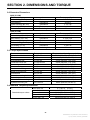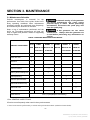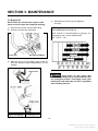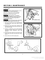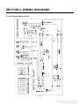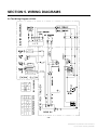
1
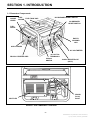
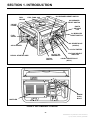
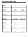
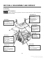
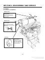
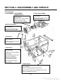
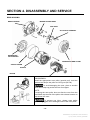
Service Manual HomeSite Power 2400 (2EGMBB-5267) 3500 (2.5EGMBG-5268) Portable Generator Set Printed in U. S. A. 03-06 914-0500 Redistribution or publication of this document, by any means, is strictly prohibited. SAFETY PRECAUTIONS Thoroughly read the OPERATOR’S MANUAL before operating the generator set. Safe operation and top performance can only be attained when equipment is operated and maintained properly. The following symbols, found throughout this manual, alert you to potentially dangerous conditions to operators, service personnel and equipment. Gasoline is Flammable / Explosive • Refuel the generator set outdoors only. • Static electric sparks caused by fuel flowing through a service station pump nozzle can ignite gasoline. Never fill the generator set with a service station pump nozzle. Instead, fill a safety tank sitting on the ground and then slowly transfer fuel to the generator set from the safety tank. • DO NOT fill fuel tanks while the engine is running. A hot engine can ignite the fuel. • To prevent fire due to fuel leakage, always close the fuel valve and let the generator set cool before transporting it or storing it in a confined space. • DO NOT SMOKE OR ALLOW AN OPEN FLAME near the generator set. Keep flames, sparks, electrical switches, pilot lights, electrical arcs, arc-producing equipment and all other sources of ignition well away. This symbol alerts you to an immediate hazard that will result in severe personal injury or death. This symbol alerts you to a hazard or unsafe practice that can result in severe personal injury or death. This symbol alerts you to a hazard or unsafe practice that can result in personal injury or damage to equipment or property. Electricity, fuel, exhaust, moving parts and batteries present hazards against which precautions must to taken to prevent severe personal injury or death. Generator Voltage is Deadly • DO NOT CONNECT THE GENERATOR SET DIRECTLY TO ANY BUILDING ELECTRICAL SYSTEM. Back-feed could cause electrocution of utility line workers and damage to equipment. An approved switching device must be used to prevent interconnections. A trained and experienced electrician must make electrical connections when the generator set is used for emergency power. • Make sure clothing, shoes and skin are dry when handling electrical equipment. • Never operate the generator set in rain or snow or when it is sitting on wet ground. Exhaust Gas Is Deadly • Operate the generator set outdoors only. Stay away from the exhaust outlet. • Make sure generator set exhaust will not enter windows, doors, vents or air intakes of adjacent buildings, vehicles or boats. • NEVER USE THE GENERTOR SET INSIDE a home, garage, crawl space, barn, shed, cabin, boat, boat house, RV or tent, or in a confined outdoor space such as an alley, ditch, parking garage or courtyard, or in any other space where exhaust can accumulate. Note that HAZARDOUS CARBON MONOXIDE LEVELS FROM ENGINE EXHAUST CAN ACCUMULATE INDOORS EVEN WHEN ALL WINDOWS AND DOORS ARE OPEN AND FANS ARE RUNNING. Moving Parts Can Cause Severe Personal Injury or Death • Before performing any maintenance on the generator set, disconnect the spark plug wire. • Always keep hands away from moving parts. • Do not wear loose clothing or jewelry while servicing the generator set. Loose clothing and jewelry can become caught in moving parts. Jewelry can short out electrical contacts causing sparks, flame and electrical shock. • Make sure that fasteners and clamps on the generator set are tight. Keep guards in position over fans, rotors, etc. a Redistribution or publication of this document, by any means, is strictly prohibited. SAFETY PRECAUTIONS • Benzene and lead may be found in gasoline Battery Gases are explosive • Wear safety glasses when servicing batteries. • Do not smoke. • To reduce arcing when disconnecting or reconnecting battery cables, always disconnect the negative (–) cable of the battery first and reconnect it last. • General Precautions • • Keep children away from the generator set. • Wear hearing protection when near an operating generator set. • Keep a multi-class ABC fire extinguisher • readily at hand. Class A fires involve ordinary combustible materials such as wood and cloth. Class B fires involve combustible and flammable liquids and gaseous fuels. Class C fires involve live electrical equipment. (ref. NFPA No. 10) • and have been identified by some state and federal agencies as causing cancer or reproductive toxicity. Do not ingest, inhale or contact gasoline. Used engine oils have been identified by some state and federal agencies as causing cancer or reproductive toxicity. Do not ingest, inhale or contact used engine oil or its vapors. Keep the generator set clean and dry at all times. Excess grease and oil can catch fire and/or accumulate dirt, which can cause overheating. Do not store anything on the generator set, such as oil cans, oily rags, chains or wooden blocks. A fire could result or operation could be adversely affected Do not work on the generator set when you are mentally or physically fatigued or have consumed alcohol or drugs. Improper service or repairs can create an unsafe condition that can cause your customer or others to be seriously hurt or killed. Follow the procedures and precautions in this manual and other service materials carefully. Failure to properly follow instructions and precautions can cause you to be seriously hurt or killed. Follow the procedures and precautions in this manual carefully. b Redistribution or publication of this document, by any means, is strictly prohibited. TABLE OF CONTENTS Title Page SECTION 1 INTRODUCTION 1-1 Generator Components 1-2 Specifications SECTION 2 DIMENSIONS AND TORQUE 2-1 Engine Dimensions 2-2 Generator Dimensions 2-3 Torque Specification 2-4 Standard Torques Specification SECTION 3 MAINTENANCE 3-1 Maintenance Schedule 3-2 Engine Oil 3-3 Air Cleaner 3-4 Fuel Sediment Cup Cleaning 3-5 Spark Arrester 3-6 Spark Plug 3-7 Valve Clearance 3-8 Governor SECTION 4 DISASSEMBLY AND SERVICE 4-1 Troubleshooting 4-1-1 Hard Starting 4-1-2 Low Power 4-1-3 Speed Unstable 4-1-4 Low Speed Voltage 4-1-5 Exhaust Color Abnormal 4-1-6 No AC Output Voltage 4-1-7 No DC Output Voltage 4-2 Preparing to Service 4-2-1 Safety Considerations 4-2-2 Special Tools 4-3 Disassembly Chart 4-4 Engine 4-4-1 Crankshaft / Pistion 4-4-2 Flywheel 4-4-3 Cylinder head / Valves 4-4-4 Recoil Starter / Fan Cover 4-4-5 Air Cleaner 4-4-6 Carburetor 4-5 Generator 4-5-1 Fuel Tank 4-5-2 Muffler 4-5-3 Generator 4-5-4 Control Panel SECTION 5 WIRING DIAGRAMS 5-1 The Wiring Diagram of 2400 5-2 The Wiring Diagram of 3500 1 1 3 4 4 6 6 6 7 7 8 9 10 10 11 12 12 13 13 13 14 15 16 17 18 18 19 19 19 20 21 21 27 29 33 36 37 38 38 39 40 44 50 50 51 c Redistribution or publication of this document, by any means, is strictly prohibited. SECTION 1. INTRODUCTION 1-1 Generator Components CHOKE LEVER FUEL FUEL TANK CAP GAUGE DC BREAKER RESET SWITCH AC BREAKER RESET SWITCH FUEL VALVE EARTH GROUND LUG AIR CLEANER AC VOLTMETER 12 VOLT DC TERMINALS RECOIL STARTER GRIP ON/OFF SWITCH 120VAC RECEPTACLE (GFCI) SPARK PLUG BOOT MUFFLER FIGURE 1. 2400 COMPONENT LOCATIONS -1Redistribution or publication of this document, by any means, is strictly prohibited. SECTION 1. INTRODUCTION FUEL GAUGE DC BREAKER RESET SWITCH FUEL TANK CAP AC BREAKER RESET SWITCH CHOKE LEVER EARTH GROUND LUG AC BREAKER RESET SWITCH FUEL VALVE AC RECEPTACLE (240VAC) AIR CLEANER AC VOLTMETER RECOIL STARTER GRIP VOLTAGE SELECT 12 VOLT DC SWITCHE TERMINALS ON/OFF 120VAC RECEPTACLE SWITCH (GFCI) SPARK PLUG BOOT MUFFLER FIGURE 2. 3500 COMPONENT LOCATIONS -2Redistribution or publication of this document, by any means, is strictly prohibited. SECTION 1. INTRODUCTION 1-2 Specifications 2400 3500 60 Hz 60 Hz 120 Volts 120 / 240 Volts Rated Power 2000 Watts 2500 Watts Rated Current 16.6 Amps 20.8 / 10.4 Amps 12 VDC / 8.3 Amps 12 VDC / 8.3 Amps GENERATOR AC OUTPUT: Frequency (Hertz) Voltage DC OUTPUT: ENGINE Engine Type Single Cylinder, Forced Air Cooling, 4-Stroke Engine Speed (RPM) 3600 3600 Gasoline Gasoline 0.63 US qt (0.6 L) 0.63 US qt (0.6 L) Spark Plug Type F7RTC F7RTC Spark Plug Gap 0.028 in. (0.7 mm) 0.028 in. (0.7 mm) 0.0039 /0.006 inches (0.10/ 0.15 mm) 0.0039 /0.006 inches (0.10 / 0.15 mm) 20° BTDC 20° BTDC Starting System Recoil Recoil Displacement 197 cc 197 cc 99.9 lb (45 kg) 106.6 lb (48 kg) Length 24.1 inches (612 mm) 24.1 inches (612 mm) Width 19.6 inches (497 mm) 19.6 inches (497 mm) Height 19.3 inches (490 mm) 19.3 inches (490 mm) 4.0 US gal (15 L) 4.0 US gal (15 L) 13 Hours 12 Hours Fuel Engine Oil Capacity Engine Valve Lash (Intake / Exhaust) Ignition Timing (fixed) GENERATOR SET Dry Weight Dimensions: Fuel Tank Capacity Operating Time at Rated Output -3Redistribution or publication of this document, by any means, is strictly prohibited. SECTION 2. DIMENSIONS AND TORQUE 2-1 Engine Dimensions 2400 Part Engine Item Maximum speed Idle speed Cylinder compression Cylinder Sleeve I.D. Cylinder head Warpage Piston Skirt O.D. Factory Specification 3750±150 rpm 1400±150 rpm 6.0-8.5 kg/cm (1.5 – 2.13 kg/in)at 600 rpm Allowable limit - 68.015 mm (2.6778 in) 68.165 mm (2.6837 in) 18.002 mm (0.7087 in) 17.998 mm (0.7086 in) 0.10 mm (0.004 in) 67.845 mm (2.6711 in) 0.12 mm (0.005 in) 18.048 mm (0.7105 in) 17.954 mm (0.7068 in) Piston -to- piston pin bore clearance 0.004-0.016 mm (0.00016-0.0006 in) 0.06 mm (0.002in) Ring side clearance Top/second/oil 0.015-0.045 mm (0.0006-0.0018 in) 0.15 mm (0.0006 in) 67.985 mm (2.6766 in) Piston-to-cylinder clearance 0.030-0.050 mm (0.0012-0.0020 in) Piston pin bore I.D. Pin O.D. Piston rings Ring end gap Top/ second Oil 0.2-0.4 mm (0.008-0.016 in) 1.0 mm (0.04 in) Ring Width Top/ second 1.5 mm (0.06 in) 2.5 mm (0.10 in) 1.37 mm (0.054 in) 2.37 mm (0.093 in) Small end I.D. (Pin End) 18.007 mm (0.7089 in) 18.07 mm (0.711 in) Big end I.D. (Crankshaft) 30.015 mm (1.1817 in) 30.0667 mm (1.1837 in) 0.030-0.050 mm (0.0012-0.0020 in) 0.12 mm (0.0048 in) 0.1-0.7 mm (0.004-0.028 in) 1.1 mm (0.043 in) 29.985 mm (1.181 in) 29.92 mm (1.178 in) Oil Connecting rod Big end oil clearance Big end side clearance Crankshaft - Crankshaft O.D. (Connecting rod Big end) -4Redistribution or publication of this document, by any means, is strictly prohibited. SECTION 2. DIMENSIONS AND TORQUE 2400 Part Item Valves Valve Lash Factory Specification IN EX Stem O.D. IN EX Guide I.D. IN/ EX Stem clearance IN EX Seat width Spring fee length Camshaft Cam height IN EX Camshaft O.D. Crankcase cover Spark plug Camshaft-holder I.D. Gap Ignition coil Resistance Air gap Primary coil Secondary coil (at flywheel) 0.10±0.02 mm (0.004±0.001 in) 0.15±0.02 mm (0.006±0.001 in) 5.48 mm (0.216 in) 5.47 mm (0.215 in) 5.50 mm (0.217 in) 0.02-0.044 mm (0.0008-0.0017 in) 0.06-0.087 mm (0.0024-0.0034 in) 0.8 mm (0.03 in) 30.0 mm (1.18 in) 27.7 mm (1.09 in) 27.75 mm (1.093 in) 13.984 mm (0.5506 in) 14.0 mm (0.55 in) 0.7-0.8 mm (0.028-0.031 in) 0.8-1.0 Ω 5.9-7.1 KΩ 0.4±0.2 mm (0.016±0.008 in) Allowable limit 5.318 mm (0.2094 in) 5.275 mm (0.2077 in) 5.572 mm (0.2194 in) 0.10mm (0.004 in) 0.12 mm (0.005 in) 2.0mm (0.08 in) 28.5 mm (1.122 in) 27.45 mm (1.081 in) 27.5 mm (1.083 in) 13.916 mm (0.5479 in) 14.048 mm (0.5531 in) - -5Redistribution or publication of this document, by any means, is strictly prohibited. SECTION 2. DIMENSIONS AND TORQUE 2-2 Generator Dimensions 2400 (2.0 kW) Part Main winding (R / Bu) Field winding Exciter winding (Bu / Bu) DC winding (G / G) Carbon brush 3500 (2.5 kW) Part Main windingⅠ(Br / W) Main windingⅡ(R / Bu) Field winding Exciter winding (Bu / Bu) DC winding (G / G) Carbon brush Item Resistance Resistance Resistance Resistance Brush length Factory specification 0.51-0.53 Ω 40-50 Ω 3.1-3.3 Ω 0.4-0.6 Ω 5-9 mm Item Resistance Factory specification 0.76-0.79 Ω Resistance Resistance Resistance Resistance Brush length 0.76-0.79 Ω 35-45 Ω 1.5-1.7 Ω 0.4-0.6 Ω 5-9 mm 2-3 Torque Specification Part Cylinder head bolt Pivot bolt Pivot adjusting nut Crankcase cover bolt Connecting rod bolt Air cleaner wing nut Air cleaner mounting nut Muffler mounting bolt Oil drain bolt Fuel tank mounting bolt/ nut Fuel valve joint nut Oil level switch mounting nut Flywheel mounting nut Fastener size 8×1.25×55 mm 6×0.5 mm 6×1.25 mm 8×1.25×32 mm 7×1.25 mm 6×1.0 mm 6×1.0 mm 8×1.25 mm 10×1.5 mm 6×1.0 mm 10×1.25 mm 10×1.25 mm 14×1.25 mm Torque values N· m (kg· cm, lb·ft) 26-28 (260-280, 18.8-20.2) 8-12 (80-120, 5.8-8.7) 22-26 (220-260, 15.9-18.8) 24-26 (240-260, 17.4-18.8) 12-14 (120-140, 8.7-17.4) 7-10 (70-100, 5.1-7.2) 7-10 (70-100, 5.1-7.2) 20-28 (200-280, 14.5-20.2) 20-25 (200-250, 14.5-18.1) 8-12 (80-120, 5.8-8.7) 20-25 (200-250, 14.5-18.1) 8-12 (80-120, 5.8-8.7) 80-90 (800-900, 58-865.3) 2-4 Standard Torques Specification Standard torque values 5 mm bolt, nut 6 mm bolt, nut 8 mm bolt, nut 10 mm bolt, nut 12 mm bolt, nut 4-7 (40-70, 2.9-5.1) 8-12 (80-120, 5.8-8.7) 20-28 (200-280, 14.5-20.2) 35-40 (350-400, 14.5-20.2) 50-60 (500-600, 36.2-43.4) -6Redistribution or publication of this document, by any means, is strictly prohibited. SECTION 3. MAINTENANCE 3-1 Maintenance Schedule Periodic maintenance is essential for top performance. Use Table 3 as a guide. Under hot or dusty operating conditions some maintenance operations should be performed more frequently, as indicated by the footnotes in the table. Accidental starting of the generator set during maintenance can cause severe personal injury or death. Before performing maintenance, disconnect the spark plug wire from the spark plug. Keep a log of maintenance performed and the hours run. Recording maintenance will help you keep it regular and provide a basis for supporting warranty claims. A hot generator set can cause severe burns. Always allow the generator set to cool before performing any maintenance or service. TABLE 3. PERIODIC MAINTENANCE SCHEDULE SERVICE INTERVAL SERVICE THESE ITEMS EACH USE FIRST MONTH OR MONTHS OR 20 HOURS General Inspection ×1 Check Oil Level × Test GFCI × Change Engine Oil EVERY 3 50 HOURS × EVERY EVERY 6 EVERY MONTH MONTHS OR YEAR OR 100 HOURS 300 HOURS × Clean Air Cleaner ×2 Clean Cylinder Cooling Fins ×2 Clean Spark Plug × Clean the Spark Arrestor x Clean Fuel Sediment Cup ×3 Clean Fuel Tank ×3 Adjust Valve Clearance ×3 Check fuel line Every 2 years(Replace if necessary) 3 1.See GENERAL INSPECTIONS. 2.Service more frequently when used in dusty environments. 3. These items must be performed by a trained and experienced mechanic (authorized Onan dealer). -7- Redistribution or publication of this document, by any means, is strictly prohibited. SECTION 3. MAINTENANCE 3-2 Engine Oil 5) NOTE: Drain the oil while the engine is still warm to assure rapid and complete draining. 1) Remove the oil filler cap and drain plug. 2) Drain the oil from the crankcase. Reinstall the oil filler cap and tighten it securely. RECOMMENDED ENGINE OIL: SAE 10W-30 is recommended for general, all temperature use: service classification SG·SF/CC·CD. 20W-50 20W-40 Oil filler cap 10W-40 Oil drain bolt (M10) 3) Reinstall the drain plug securely. 4) Add new oil up to the bottom edge of the oil filler hole with the engine stopped and in a level position. 10W-30 Lower level Used motor oil may cause skin cancer if repeatedly left in contact with the skin for prolonged periods. Thoroughly wash your hands with soap and water as soon as possible after handling used oil. Engine Oil Capacity 1.16 US qt (1.1 L) -8- Redistribution or publication of this document, by any means, is strictly prohibited. SECTION 3. MAINTENANCE 3-3 Air Cleaner A dirty air cleaner will restrict air flow to the carburetor. To prevent carburetor malfunction, service the air cleaner regularly. Service more frequently when operating the generator in extremely dusty areas. Using gasoline or flammable solvent to clean the filter element can cause a fire or explosion. Use only soapy water or nonflammable solvent. AIR CLEANER COVER Never run the generator without the air cleaner. Rapid engine wear will result. 1) CLIP Remove the cleaner cover by unsnapping the two spring clips. Clean more often in dusty environments 2) Remove the two foam filter elements and thoroughly wash them with soap and water. Let them dry thoroughly. 3) Knead in 1 teaspoon (5 cm3) of clean engine oil into each foam filter element. The oil should be distributed evenly throughout each filter elements. 4) Reinstall the filter elements, the gray filter first (finer pores) and then the black filter (larger pores). 5) Secure the cover with the spring clips. AIR CLEANER ELEMENT SOAP & WATER ENGINE OIL SQUEEZE DRY -9- Redistribution or publication of this document, by any means, is strictly prohibited. SECTION 3. MAINTENANCE 3-5 Spark Arrester 3-4 Fuel Sediment Cup Cleaning The sediment cup prevents dirt or water which may be in the fuel tank from entering the carburetor. If the engine has not been run for a long time, the sediment cup should be cleaned. 1) 2) 3) 4) A hot muffler can cause severe burns. Allow the generator set to cool before servicing the muffler. Refer to MAINTENANCE SCHEDULE for scheduled spark arrester cleaning. After letting the generator set cool down, remove the spark arrester screen. Inspect for damage, and replace if defective. Clean any deposits on the screen with a wire brush. Reinstall the spark arrester, and tighten the screw securely. Turn the fuel valve to the OFF position. Remove the sediment cup, and o-ring. Clean the sediment cup, and o-ring, in nonflammable or high flash point solvent. Reinstall o-ring, and sediment cup. Turn the fuel valve ON and check for leaks. FUEL VALVE SEDIMENT CUP (10 mm) FUEL FILTER O-RING SEDIMENT CUP Gasoline is extremely flammable and is explosive. Do not smoke or allow flames or sparks in the area. After reassembly, check for leaks, and make sure the area is dry before starting the engine. - 10 - Redistribution or publication of this document, by any means, is strictly prohibited. SECTION 3. MAINTENANCE 7) 3-6 Spark Plug To ensure proper engine operation, the spark plug must be properly gapped and free of deposits. 8) If the engine has been running, the spark plug and muffler will be very hot. Be careful not to touch the muffler or spark plug. 1) Turn off generator. 2) Remove the spark plug cap. 3) 4) If installing a new spark plug, tighten l/2 turn after the spark plug seats to compress the washer. If reinstalling a used spark plug, tighten l/8 - l/4 turn after the spark plug seats to compress the washer. Clean any dirt from around the spark plug base. Use the wrench supplied in the tool kit to remove the spark plug. PLUG WRENCH Check that the spark plug washer is in good condition, and thread the spark plug in by hand to prevent cross-threading. After the spark plug is seated, tighten with a spark plug wrench to compress the washer. The spark plug must be securely tightened. An improperly tightened spark plug could damage the engine. SPARK PLUG TORQUE (20N•m-25N•m) Never use spark plugs which have an improper heat range. Use only the recommended spark plugs or equivalent. PLUG CAP 5) 6) Visually inspect the spark plug. Discard it if the insulator is cracked or chipped. Clean the spark plug with a wire brush if it is to be reused. Measure the plug gap with a feeler gauge. Correct as necessary by carefully bending the side electrode. 0.7-0.80mm SIDE ELECTRODE METAL BRUSH The gap should be: 0.70-0.80 mm (0.028-0.031 in). - 11 - Redistribution or publication of this document, by any means, is strictly prohibited. SECTION 3. MAINTENANCE 3-7 Valve Clearance Valve clearance inspection and adjustment must be performed with the engine cold. 1) Remove the cylinder head cover, and set the piston at top dead center of the compression stroke (both valves fully closed). Pull the starter until the piston is at top dead center of the compression or exhaust stroke. 2) Insert a feeler gauge between the rocker arm and valve to measure valve clearance. Standard valve clearance IN. EX. 0.10±0.02 mm (0.004±0.001 in) 0.2±0.02 mm (0.008±0.001 in) 3-8 Governor ROCKER ARM 1) Take down the fuel tank. 2) Loosen the nut on the governor arm pinch bolt. 3) Move the arm until the throttle is completely open, and hold it in that position. 4) Rotate the governor arm shaft as far as it will go in same direction it was just moved by the governor arm, and then tighten the governor arm pinch bolt. LOCK NUT 10N•m-140N•m 5) Whether check the arm and throttle move smoothing. 6) 7) Start the engine and adjust the limiting screw to produce the standard until the engine warm up to normal operating temperature. PIVOT To increase valve clearance, screw lock nut out. To decrease valve clearance, screw lock nut in. 3) Install the fuel tank. Idle speed GOVERNOR NUT SPRING If adjustment is necessary, proceed as follows: a) Hold the rocker arm pivot and loosen the pivot lock nut. b) Turn the rocker arm pivot to obtain the specified clearance. c) Retighten the lock nut while holding the rocker arm pivot. d) Recheck valve clearance after tightening the lock nut. 3600±150rpm GOVERNOR ARM PINCH BOLT GOVERNOR ARM SHAFT nut GOVERNOR ARM THROTTLE LIMITING SCREW ANTI-SURGE SPRING - 12 - Redistribution or publication of this document, by any means, is strictly prohibited. SECTION 4. DISASSEMBLY AND SERVICE ENGINE FLOODED too much fuel 4-1 Troubleshooting (TRY AGAIN AFTER A FEW MINUTES) 4-1-1 Hard Starting FUEL low FUEL SYSTEM (ADD FUEL INTO FUEL TANK) FUEL FILTER clogged (SEE 3-4) CARBURETOR out of adjustment (SEE 4-4-6) AIR FILTER dirty (SEE 3-3) OIL low (SEE 3-2) SPARK PLUG GAP incorrect (SEE 3-6) SPARK PLUG CAP faulty (SEE 4-4-2) HARD STARING IGNITION SYSTEM IGNITION COIL GAP incorrect (SEE 4-4-2) IGNITION COIL faulty (SEE 4-4-2) START SWITCH faulty (SEE 4-5-4) OIL ALERT SYSTEM faulty (SEE 4-4-1) VALVE LASH incorrect (SEE 3-7) CYLINDER HEAD GASKET faulty (SEE 4-4-3) CYLINDER HEAD BOLT faulty COMPRESSION SYSTEM (SEE 4-4-3) VALVE faulty (SEE 4-4-3) CYLINDER / PISTON / PISTON RING worn (SEE 4-4-1) CAMSHAFT wore (SEE 4-4-1) - 13 - Redistribution or publication of this document, by any means, is strictly prohibited. SECTION 4. DISASSEMBLY AND SERVICE 4-1-2 Low Power FUEL poor (ADD CLEAN FRESH FUEL INTO TANK) FUEL FILTER clogged (SEE 3-4) FUEL SYSTEM CARBURETOR out of adjustment (SEE 4-4-6) CHOKE ROD not open (MOVE TO “RUN” POSITION) AIR FILTER dirty (SEE 3-3) SPARK PLUG faulty IGNITION SYSTEM (SEE 3-6) CAMSHAFT worn (SEE 4-4-1) CYLINDER / PISTON / PISTON RING worn (SEE 4-4-1) Low Power COMPRESSION SYSTEM VALVE LASH out of Spec (SEE 3-7) VALVE SEAT worn or damaged (SEE 4-4-3) COOLING FAN dirty (CLEAN) COOLING CYLINDER FINS dirty (CLEAN) OTHER MUFFLER clogged (SEE 4-5-2) GOVERNOR out of adjustment (SEE 3-8) ELECTRICAL LOADS too high (REMOVE EXTRA LOADS) - 14 - Redistribution or publication of this document, by any means, is strictly prohibited. SECTION 4. DISASSEMBLY AND SERVICE 4-1-3 Speed Unstable FUEL low / poor quality / contaminated (ADD NEW FUEL INTO FUEL TANK) FUEL SYSTEM FUEL FILTER clogged (SEE 3-4) CARBURETOR clogged (SEE 4-4-6) GOVERNOR out of adjustment GOVERNOR SYSTEM (SEE 3-8) ANTI-SURGE SPRING incorrect (REPLACE) SPEED UNSTABLE SPARK PLUG spark plug wire faulty COMPRESSION SYSTEM (SEE 4-4-2) CAMSHAFT worn (SEE 4-4-1) OIL low level OTHER (ADD NEW OIL) ELECTRICAL LOADS too high (REMOVE EXTRA LOADS) - 15 - Redistribution or publication of this document, by any means, is strictly prohibited. SECTION 4. DISASSEMBLY AND SERVICE 4-1-4 Low Speed / Voltage AIR FILTER dirty (SEE 3-3) FUEL poor / contaminated FUEL SYSTEM (ADD NEW FUEL) CARBURETOR has water (SEE 4-4-6) CHOKE LEVER not open (PUSH CHOKE ROD) LOW SPEED / VOLTAGE GOVERNOR out of adjustment GOVERNOR SYSTEM (SEE 3-8) ANTI-SURGE SPRING incorrect (REPLACE) MUFFLER clogged (SEE 4-5-2) OTHER ALTERNATOR temperature is too high (SEE 4-5-3) (CLEAN ALTERNATOR FAN AND END COVER) ELECTRICAL LOADS too high (REMOVE EXTRA LOADS) - 16 - Redistribution or publication of this document, by any means, is strictly prohibited. SECTION 4. DISASSEMBLY AND SERVICE 4-1-5 Exhaust Color Abnormal AIR FILTER dirty (SEE3-3) BLACK CARBURETOR faulty (SEE 4-4-6) LOAD excessive (REMOVE EXTRA LOAD) ENGINE temperature is too low EXHAUST COLOR ABNORMAL (NORMAL WHEN STARTING) WHITE FUEL contaminated (ADD FRESH FUEL) FUEL contaminated with oil (CHANGE TO FRESH FUEL) CYLINDER / PISTON / PISTON RING worn BLUE (SEE 4-4-1) OIL too much (SEE 3-2) BREATHER icing issue (CLEAN BREATHER) - 17 - Redistribution or publication of this document, by any means, is strictly prohibited. SECTION 4. DISASSEMBLY AND SERVICE 4-1-6 No AC Output Voltage ENGINE SPEED abnormal (CHECK IT AND ADJUST) STATOR MAIN COIL defective (SEE 4-5-3) BRUSH defective NO AC OUTPUT VOLTAGE (SEE 4-5-3) EXCITATION VOLTAGE too low (SEE 4-5-3) AVR defective (SEE 4-5-3) BREAKER tripped (RESET BREAKERS) 4-1-7 No DC Output Voltage BREAKER tripped NO DC OUTPUT VOLTAGE (RESET BREAKERS) OTHER REASON - 18 - Redistribution or publication of this document, by any means, is strictly prohibited. SECTION 4. DISASSEMBLY AND SERVICE TABLE 4-1 HAZARDS AND THEIR SOURCES 4-2 Preparing to Service • Leaking or spilled fuel 4-2-1 Safety Considerations There are hazards in servicing gensets. Study Safety precautions and become familiar with the hazards listed in table 4-1. Note the following safeguards and ways of avoiding hazards. Fire and Explosion • Oily rag improperly stored • Flammable liquids improperly stored • Use personal protection: Wear appropriate protective safety equipment, such as safety shoes and safety glasses. Burns • Do not wear rings or jewelry and do not wear loose or damp clothing that might get caught in equipment or conduct electricity. Poisonous Gas • Reduce the hazard: A safety, order workshop area and well-maintained reduce the hazard potential. Keep guards and shields in place on machinery and maintain equipment in good working condition. Store flammable liquids in approved containers; away form fire, flame, spark, pilot light, switches, arc-producing equipment and other ignition sources. Keep the workshop clean and well-lighted and provide adequate ventilation. • Develop safe work habits: Unsafe actions cause accidents with tools and machines. Be familiar with the equipment and know how to use them safely. Use the correct tool for the job and check its condition before starting. Comply with the warnings in this manual and take special precautions when working around electrical equipment. Do not work alone if possible and take no risks. • Be prepared for an accident: Keep fire extinguishers and safety equipment nearby. Agencies such as the Red Cross and public safety departments offer courses in first aid, CPR and fire control. Take advantage of this information to be ready to respond to an accident. Learn to be safety-conscious and make safety procedures part of the work routine. • Hydrogen gas from battery • Hot exhaust pipes • Hot engine and generator surfaces • Operating genset where exhaust gases can accumulate • Improper generator connections Electrical Shock (AC) • Faulty wiring • Working in damp conditions • Jewelry touching electrical components Rotating Machinery Slippery Surfaces • Fan guards not in place • Leaking or spilled oil Heavy • Removing genset form vehicle Objects • Removing heavy components 4-2-2 Special Tools Engine A complete set of standard and metric shop tools are required to service the engine. Control and Generator A complete set of standard and metric shop tools are required to service the control and generator. Also needed are: Lead or dead blow hammer Battery hydrometer Torque wrench VOM millimeter Frequency meter Armature growler Load bank Jumper wires Rotor Puller - 19 - Redistribution or publication of this document, by any means, is strictly prohibited. SECTION 4. DISASSEMBLY AND SERVICE 4-3 Disassembly Chart END COVER MUFFLER AVR BRUSH FUEL TANK CONTROL BOX MOUNT RUBBER FRAME REAR HOUSING STATOR ROTOR ENGINE CARBURATOR AIR CLEANER FLYWHEEL STARTER MOTOR FAN COVER RECOIL STARTER GENERATOR DISASSEMBLY This chart is a quick-reference guide for disassembling the product. Be sure to follow the sequence shown here for better and safer work. Example:To remove the frame. a) Remove the end cover. b) Remove the control box. c) Remove the fuel tank. d) Remove the muffler. e) Remove the frame. - 20 - Redistribution or publication of this document, by any means, is strictly prohibited. SECTION 4. DISASSEMBLY AND SERVICE 4-4 Engine 4-4-1 Crankshaft / piston a.DISASSEMBLY/ ASSEMBLY Crankshaft REASSEMBLY: Check that the decompressor weight moves smoothly, and the spring is not weak or worn. PISTON REASSEMBLY: Install with the triangle mark toward the push rods. DECOMPRESSOR WEIGHT VALVE LIFTER REASSEMBLY: Install the tappets immediately before installing the camshaft. OIL LEVER SWITCH OIL ALERT UNIT CONNECTING ROD CAP REASSEMBLY: Install with the oil dipper toward the camshaft . The ribs on the cap and connecting rod must be aligned. CRANKSHAFT REASSEMBLY: Push in until the bearing touches the crankcase. Be careful not to damage the oil seal. - 21 - Redistribution or publication of this document, by any means, is strictly prohibited. SECTION 4. DISASSEMBLY AND SERVICE b.PISTON/ PISTON RING PISTON RING REASSEMBLY: 1) Install all rings with the markings facing upward. 2) Be sure that the top (chrome plated) and second rings are not interchanged. 3) Check that the rings rotate smoothly after installation. 4) Space the piston ring end gaps 120 degrees apart, and do not align the gaps with the piston pin bore. TOP RING (CHROME PLATED) OIL RING MARKING SECOND RING PISTON PISTON PIN PISTON PIN CLIP REASSEMBLY: Install by setting one end of the clip in the piston groove, holding the other end with long-nosed pliers, and rotating the clip in. Do not align the end gap of the clip with the cut-out in the piston pin bore. PISTON PIN REASSEMBLY: Install the connecting rod with the long end toward the triangle marked side of the piston. - 22 - Redistribution or publication of this document, by any means, is strictly prohibited. SECTION 4. DISASSEMBLY AND SERVICE c.CAMSHAFT/ CRANKSHAFT d.OIL LEVEL SWITCH Ckeck continuity of the switch with an ohmmeter. REASSEMBLY: Align the index marks on the camshaft and timing gear. 1) Hold the switch in its normal position. The ohmmeter should read zero resistance. 2) Hold the switch upside down. The ohmmeter should read infinity (∞) resistance. CRANKSHAFT INDEX MARKS CAMSHAFT 3) Inspect the float by dipping the switch into a container of oil. The ohmmeter reading should go from zero to infinty as the switch is lowered. CRANKSHAFT (OFF) (ON) - 23 - Redistribution or publication of this document, by any means, is strictly prohibited. SECTION 4. DISASSEMBLY AND SERVICE d.INSPECTION PISTON RING SIDE CLEARANCE Factory Allowable limit Specification 0.030-0.060 mm 0.15 mm (0.0012-0.0024 in) (0.006 in) CYLINDER ID(Inside Diameter) Factory Specification Allowable limit 68.015 mm 68.165 mm (2.6778 in) (2.684 in) PISTON RING END GAP Factory Allowable limit Specification 0.2-0.4 mm 1.0 mm (0.008-0.016 in) (0.04 in) PISTON SKIRT OD(Outside Diameter) Factory Specification Allowable limit 67.985 mm 67.845 mm (2.6766 in) (2.6711 in) PISTON-TO CYLINDER CLEARANCE Factory Specification Allowable limit 0.03-0.05 mm 0.12 mm (0.0012-0.002 in) (0.005 in) PISTON PIN OD Factory Specification 17.998 mm (0.7086 in) Allowable limit 17.954 mm (0.7068 in) - 24 - Redistribution or publication of this document, by any means, is strictly prohibited. SECTION 4. DISASSEMBLY AND SERVICE CONNECTING ROD BIG END ID Factory Allowable limit Specification 30.015 mm 30.066 mm (1.1817 in) (1.1837 in) PISTON PIN BORE ID Factory Allowable limit Specification 18.002 mm 18.048 mm (0.7087 in) (0.7105 in) PISTON-TO-PISTON PIN BORE CLEARANCE Factory Allowable limit Specification 0.004.016 mm 0.08 mm (0.00016-0.0006 in) (0.0.003 in) CONNECTING ROD SMALL END ID Factory Allowable limit Specification 18.006 mm 18.07 mm (0.7089 in) (0.711 in) CRANKPIN OD Factory Specification 29.985 mm (1.181 in) Allowable limit 29.92 mm (1.178 in) CONNECTING ROD BIG END SIDE CLEARANCE Factory Allowable limit Specification 0.1-0.7 mm 1.1 mm (0.0040.028 in) (0.043 in) - 25 - Redistribution or publication of this document, by any means, is strictly prohibited. SECTION 4. DISASSEMBLY AND SERVICE CAMSHAFT DIAMETER Factory Specification IN 27.7 mm (1.09in) EX 27.75 mm (1.093 in) Allowable limit 27.45 mm (1.081 in) 27.50mm (1.083 in) CAMSHAFT HOLDER ID Factory Specification 14.00 mm (0.55 in) Allowable limit 16.048 mm (0.5531 in) CAMSHAFT CAM DIAMETER Factory Allowable limit Specification 13.916 mm 13.984 mm (0.5506 in) (0.5479 in) - 26 - Redistribution or publication of this document, by any means, is strictly prohibited. SECTION 4. DISASSEMBLY AND SERVICE 4-4-2 Flywheel a.DISASSEMBLY/ ASSEMBLY SPARK PLUG LEAD REASSEMBLY: Clamp securely to the crankcase with the two clamps. WOODRUFF KEY REASSEMBLY: After installing the flywheel, check to be sure that the woodruff key is still in its slot on the crankshaft. SPARK PLUG LEAD REASSEMBLY: Check for cracked or damaged insulation; replace if necessary. - 27 - Redistribution or publication of this document, by any means, is strictly prohibited. SECTION 4. DISASSEMBLY AND SERVICE b. INSPECTION IGNITION COIL RESISTANCE Primary side resistance value IGNITION COIL 0.8-1.0 Ω Secondary side resistance value 1. Measure the resistance of the primary coil by attaching one ohm-meter lead to the ignition coil’s primary lead while touching the other test lead to the iron core. 2. Measure the resistance of the secondary side of the coil by removing the spark plug cap and touching one test lead to the spark plug lead wire while touching the other test lead to the iron core. 0.4± 0.2 mm (0.016± 0.008 in) FLYWHEEL AIR GAP (AT FLYWHEEL) Measure the air gap between of the ignition and flywheel by thickness gauge. Air gap (at flywheel) 5.9-7.1 KΩ NOTE: A false reading will result if the spark plug cap is not removed. If the resistance is not as specified, replace the ignition coil. 0.4±0.2 mm (0.016±0.008 in) SPARK PLUG CAP Measure the resistance of the spark plug cap by attaching one ohm-meter. If the resistance is not as specified, change the spark plug cap. Spark Plug Cap 5K - 28 - Redistribution or publication of this document, by any means, is strictly prohibited. SECTION 4. DISASSEMBLY AND SERVICE 4-4-3 Cylinder Head / Valves a.DISASSEMBLY/ ASSEMBLY CYLINDER HEAD REASSEMBLY: Before installation, remove carbon deposits from the combustion chamber and inspect the valve seats. Measure the compression of the cylinder head after reassembly. CYLINDER HEAD GASKET CYLINDER HEAD BOLT CYLINDER HEAD COVER CYLINDER HEAD COVER GASKET CRANKCASE CYLINDER HEAD COVER BOLT CYLINDER HEAD BOLT CYLINDER HEAD COVER BOLT TORQUE: TORQUE: 26-28 N· m (260-280 kg· cm, 18.7-20.2 ft· lb) 12-14 N· m (120-140 kg· cm, 8.7-17.4 ft· lb) REASSEMBLY/ DISASSEMBLY: REASSEMBLY/ DISASSEMBLY: Tighten and untighten using a cross pattern. Tighten and untighen using a cross pattern. - 29 - Redistribution or publication of this document, by any means, is strictly prohibited. SECTION 4. DISASSEMBLY AND SERVICE ROCKER ARM SPARK PLUG EXHAUST VALVE REASSEMBLY: REASSEMBLY: REASSEMBLY: Check the pivot bolt, push rod and rocker arm before installing. Before installation, clean and adjust the spark plug. Check both ends for wear and check the rod for straightness. Be sure the rod ends are firmly seated in the lifter. VALVE ROTATOR REASSEMBLY: If the valve rotator is not installed, the valve may drop into the cylinder when starting the engine. PUSH ROD REASSEMBLY: Before installation, remove carbon deposits and inspect the valve. INTAKE VALVE Do not remove the valve spring retainers while the cylinder head is installed, or the valves will drop into the cylinder. VALVE HEAD DIAMETER: IN: 24 mm DISASSEMBLY: (0.94 in) Compress the value spring and slide the retainer out to the side, so the valve stem slips through the hole at the side of the retainer. REASSEMBLY: Do not interchange with the exhaust valve. EX: 22 mm (0.87 in) - 30 - Redistribution or publication of this document, by any means, is strictly prohibited. SECTION 4. DISASSEMBLY AND SERVICE b.INSPECTION STRAIGHT EDGE FEELER GAUGE CYLINDER HEAD Remove carbon deposits from the combustion chamber. Clean off any gasket material from the cylinder head surface. Check the spark plug hole and valve areas for cracks. Check the cylinder head for warpage with a straight edge and a feeler gauge. Allowable limit 0.1 mm (0.004 in) GUIDE TO STEM CLEARANCE Subtract each valve stem O.D. from the corresponding guide I.D. to the stem to guide clearance. Factory Allowable limit Specification 0.10 mm 0.02-0.044 mm IN (0.0008-0.0016 in) (0.004 in) 0.12 mm 0.06-0.087 mm EX (0.0002-0.0034 in) (0.005 in) VALVE SEAT WIDTH Measure the valve seat width. If the valve seat width is under the factory section, or over the service limit, recondition the valve seat. Factory Specification Allowable limit 0.8 mm (0.03 in) 2.0 mm (0.08 in) VALVE GUIDE ID NOTE: Ream the valve guides to remove any carbon deposits before measuring. Measure and record each valve guide I. D. Factory Specification Allowable limit 5.50 mm (0.217 in) 5.572 mm (0.2193 in) Replace the cylinder header if they are over the allowable limit. If the stem to guide clearance exceeds the Allowable limit, determine if the new guide with standard dimensions would bring the clearance within tolerance. If so, replace any guide as necessary and ream to fit. If the stem to guide clearance exceeds the allowable limit with new guides, replace the valves as well. NOTE: Recondition the valve seats whenever the valve guides are replaced. - 31 - Redistribution or publication of this document, by any means, is strictly prohibited. SECTION 4. DISASSEMBLY AND SERVICE VALVE STEM OD Inspect each valve for face irregularities, bending or abnormal stem wear. Replace the valve if necessary. Measure and record each valve stem O.D. Factory Allowable limit Specification IN 5.318 mm 5.48 mm (0.216 in) (0.2093 in) EX 5.275 mm 5.44 mm (0.214 in) (0.2077 in) Replace the valves if their O.D. is smaller than the allowable limit. VALVE SPRING FREE LENGTH Measure the free length of the valve springs. Factory Specification Allowable limit 30.0 mm (1.18 in) 28.5 mm (1.122 in) Replace the springs if they are shorter than the allowable limit. - 32 - Redistribution or publication of this document, by any means, is strictly prohibited. SECTION 4. DISASSEMBLY AND SERVICE 4-4-4 Recoil Starter / Fan Cover a.DISASSEMBLY/ ASSEMBLY FLANGE NUT 16mm STARTER PULLEY DISASSEMBLY/ REASSEMBLY: REASSEMBLY: Install by aligning the hole in the pulley with the lug on the cooling fan. Hold the flywheel by placing a screwdriver into the pulley. FAN COVER DISASSEMBLY/ REASSEMBLY: Remove and install with the recoil starter ASSY. COOLING FAN REASSEMBLY: RECOIL STARTER ASSY Install by aligning the three lugs on the rear side of the fan with the small hole in the flywheel. REASSEMBLY: Install with the starter grip position as shown. When disassembling and assembling, take care not to damage the fan blades. - 33 - Redistribution or publication of this document, by any means, is strictly prohibited. SECTION 4. DISASSEMBLY AND SERVICE b.DISASSEMBLY (RECOIL STARTER ASSY) The recoil starter can cause personal injury, Wear safety glasses. Do not let the recoil spring snap. REEL COVER REASSEMBLY: Align the ratchet with the reel cover notch. STARTER REEL REASSEMBLY: Install on the starter case after installing the return spring. RATCHET REASSEMBLY: Check for wear or damage. Note the installation direction. RETURN SPRING REASSEMBLY: Hook the outer hook in the groove of the starter reel and inner hook on the starter case tab. STARTER ROE REASSEMBLY: Install with the starter grip position as shown. - 34 - Redistribution or publication of this document, by any means, is strictly prohibited. SECTION 4. DISASSEMBLY AND SERVICE c.RECOIL STARTER ASSEMBLY c) With a short length of the rope extending from the starter reel notch, pull the end of the rope out of the case, feed it through the starter grip, and tie a knot in the end of the rope. d) Install the friction plates, friction spring, ratchet pin, guide plate, and reel cover. Tighten the reel cover bolt. e) Rotate the reel three full turns in the direction of the arrow. f) Check the operation of the ratchet by pulling the starter rope out several times. Wear gloves and eye wear to protect your hands and eyes. Do not let the return spring jump. a) b) Hook the spring outer hook in the reel groove, and install the reel on the starter case, so that the spring inner hook is hooked to the starter case tab by turning the reel counterclockwise. Feed the end of the rope through the hole in the starter reel, and tie the rope end. Wind the rope onto the direction shown, and wedge the rope end in the notch on the edge of the reel. - 35 - Redistribution or publication of this document, by any means, is strictly prohibited. SECTION 4. DISASSEMBLY AND SERVICE 4-4-5 Air Cleaner DISASSEMBLLY/ REASSEMBLY BREATHER TUBE REASSEMBLY: Connect between the air cleaner case and tappet cover. SEAL ELEMENT AIR CLEANER CASE AIR CLEANER GASKET REASSEMBLY: SEPARATOR Make sure the gasket is not damaged, broken or bent. Install correctly as shown. AIR CLEANER COVER REASSEMBLY: Make sure to seat the gasket in the groove on the edge of the case all the way around properly. - 36 - Redistribution or publication of this document, by any means, is strictly prohibited. SECTION 4. DISASSEMBLY AND SERVICE 4-4-6 Carburetor DISASSEMBLLY/ REASSEMBLY Gasoline is flammable and explosive. Close the fuel shut off valve, and drain the carburetor before servicing the carburetor. PILOT SCREW CARBURETOR BODY REASSEMBLY: REASSEMBLY: Check the screw head for wear or damage before installing. INITIAL OPENING: 1-5/8 turns out. Clean internal passages and orifices with compressed air before installing. O-RING MAIN JET REASSEMBLY: REASSEMBLY: Check for correct installation. Clean thoroughly with MAIN NOZZLE compressed air before REASSEMBLY: installation. Clean thoroughly with compressed air before FLOAT installation. REASSEMBLY: FLOAT VALVE Check for smooth movement after installing. REASSEMBLY: SET BOLT Check for worn valve or weak spring before installation. REASSEMBLY: DRAIN SCREW After assembly, check for any sign of fuel leakage. REASSEMBLY: Clean thoroughly with compressed air and check for leaks after installation. - 37 - Redistribution or publication of this document, by any means, is strictly prohibited. SECTION 4. DISASSEMBLY AND SERVICE 4-5 Generator 4-5-1 Fuel Tank DISASSEMBLLY/ REASSEMBLY Gasoline is flammable and explosive. Drain the fuel tank and fuel line before disassembly. Wipe up spilled fuel immediately. FUEL TANK CAP REASSEMBLY: Make sure that the air vent hole is clean and unclogged. Blow with compressed air if necessary. FUEL METER REASSEMBLY: After reassembly, check the operation of the float. FUEL STRAINER REASSEMBLY: Check to be sure the strainer is clean and undamaged before installation. FUEL TANK FUEL VALVE REASSEMBLY: REASSEMBLY: Wash the tank to remove sediment, Make sure the passages are not clogged. Check for fuel leakage after installation. FUEL FILTER SEDIMENT CUP REASSEMBLY: REASSEMBLY: Check to be sure the filter is clean and undamaged. Wash to remove sediment. and dry thoroughly before installation. - 38 - Redistribution or publication of this document, by any means, is strictly prohibited. SECTION 4. DISASSEMBLY AND SERVICE 4-5-2 Muffler DISASSEMBLLY/ REASSEMBLY EXHAUST PIPE REASSEMBLY: Install after removing the carbon deposits from the exhaust pipe. EXHAUST PIPE REASSEMBLY: Attach after removing the carbon from the screen with a wire brush. MUFFLER REASSEMBLY: Install after removing the carbon deposits from the muffler using a plastic hammer. - 39 - Redistribution or publication of this document, by any means, is strictly prohibited. SECTION 4. DISASSEMBLY AND SERVICE 4-5-3 Generator CRANKCASE GROMMET a. DISASSEMBLLY/ REASSEMBLY GENERATOR ASSY REASSEMBLY: REASSEMBLY: Check to be sure the grommet is inserted securely. Wipe dirt or oil off the tapered portion of the rotor and crankshaft before installing. BRUSH HOLDER ASSY DISASSEMBLY: Remove the brush holder before the rotor and stator. ROTOR BOLT REASSEMBLY: 43-47 N·m (430-470 kg·cm, 31.0-33.9 ft·lb) STATOR BOLT REASSEMBLY: Tighten in crisscross pattern in 2-3 steps. After tightening, make sure there is no clearance between the crankcase cover and stator cover. 8-12 N·m (80-120 kg·cm, 5.8-8.7 ft·lb) RUBBER MOUNT REASSEMBLY: Insert the alignment tabs onto the holes. Make sure the rubber is not chipped, hard or worn. Note the installation direction. - 40 - Redistribution or publication of this document, by any means, is strictly prohibited. SECTION 4. DISASSEMBLY AND SERVICE REAR HOUSING REAR HOUSING BRUSH HOLDER ASSY AVR ASSY AC OUTPUT TERMINAL GENERATOR COOLING FAN GENERATOR END COVER STATOR COVER STATOR ROTOR DISASSEMBLY: Install the appropriate rotor puller (special tool), hold the flywheel and torque the puller to 6.9 Kg-cm (50 ft-lb). To avoid damaging the rotor, place a wooden block and a shop rag under the rotor for support. NOTE: If torquing the rotor puller does not free the rotor from the crankshaft, tap the end of the puller with a brass hammer to help loosen the rotor. To prevent eye injury, always wear safety glasses or goggles when striking the end of the rotor puller. - 41 - Redistribution or publication of this document, by any means, is strictly prohibited. SECTION 4. DISASSEMBLY AND SERVICE b. INSPECTION CARBON BRUSH/ SLIP RING FIELD WINDING Remove the carbon brushes from the brush holder. Remove the brushes and measure resistance between the slip rings. Check the brush for length, wearing condition or any other defect. Replace if the length is less than 5 mm (0.20in). RESISTANCE NOTE: z Connect the Blue wire lead to the positive (+) side of the brush holder. z Avoid damaging the brushes when removing and installing the brush holder. Visually inspect the slip rings for dust, rust or other damage. If necessary, wipe them with a clean lint-free cloth. If they are rusted or damaged, remove the rotor and rub with fine emery cloth. 2400 40-50 Ω 2500 35-45 Ω If the specified resistance is obtained at the slip rings, but not at the brush terminals, clean or replace the brushes. If the specified resistance is not obtained at the slip rings, clean or replace the rotor. - 42 - Redistribution or publication of this document, by any means, is strictly prohibited. SECTION 4. DISASSEMBLY AND SERVICE AC OUTPUT TERMINALS Br Br W W EXCITER WINDING 2400 Using an ohmmeter, measure the resistance between the Light green/ Red and Green wires in the 4P coupler. AC OUTPUT TERMINALS RESISTANCE Br W R Br (Ⅰ) W Bu R 2400 3.1-3.3 Ω 3500 1..5-1.7 Ω Slip ring Ground ∝ If the resistance is zero or infinity, replace the stator. (Ⅱ) Bu 3500 MAIN WINDING Using an ohmmeter, measure the resistance between the AC output terminals. 2400 0.51-0.53 Ω DC WINDING RESISTANCE 3500(Ⅰ) 0.76-0.79 Ω Using an ohmmeter, measure the resistance between the brown wire leads at the DC diode connecter. 3500(Ⅱ) 0.76-0.79Ω NOTE: RESISTANCE Set the voltage selector switch to 120 V only position. If the resistance is zero or infinity, replace the stator. 0.4-0.6 Ω If the resistance is out of specification, replace the stator. - 43 - Redistribution or publication of this document, by any means, is strictly prohibited. SECTION 4. DISASSEMBLY AND SERVICE 4-5-4 Control Panel a. DISASSEMBLLY/ REASSEMBLY GENERATOR END COVER CONTROL PANEL - 44 - Redistribution or publication of this document, by any means, is strictly prohibited. SECTION 4. DISASSEMBLY AND SERVICE 2400 PANEL END COVER DC BREAKER RESET SWITCH AC BREAKER RESET SWITCHES GFCI VOLTMETER EARTH GROUND LUG ON/STOP SWITCH 12 Volt DC Terminals PANEL FRONT COVER - 45 - Redistribution or publication of this document, by any means, is strictly prohibited. SECTION 4. DISASSEMBLY AND SERVICE 3500 PANEL END COVER FUSE AND FUSE COVER DC BREAKER RESET SWITCH VOLTAGE SELECTOR WITCH AC BREAKER RESET SWITCHES AC BREAKER RESET SWITCH VOLTMETER AC RECEPTACLE (120/240VAC) EARTH GROUND LUG START/ON/STOP SWITCH GFCI 12 Volt DC Terminals PANEL FRONT COVER - 46 - Redistribution or publication of this document, by any means, is strictly prohibited. SECTION 4. DISASSEMBLY AND SERVICE 2400 DC DIODE 4P COUPLER 1) Red (+) 2) Blue (-) Blue (+) Yellow (-) GROUND CABLE AC OUTPUT TERMINAL STRIP Brown White Brown White AVR EXCITER WINDING 4P COUPLER 3) Blue 4) Green 5) White - 47 - Redistribution or publication of this document, by any means, is strictly prohibited. SECTION 4. DISASSEMBLY AND SERVICE 3500 DC DIODE 4P COUPLER 1) Red (+) 2) Blue (-) Yellow (-) Blue (+) GROUND CABLE AC OUTPUT TERMINAL STRIP Brown Brown Main Winding(Ⅰ) White White Red Red Main Winding(Ⅱ) Blue Blue EXCITER WINDING 4P COUPLER 3) Blue 4) Green 5) White AVR - 48 - Redistribution or publication of this document, by any means, is strictly prohibited. SECTION 4. DISASSEMBLY AND SERVICE b. INSPECTION AC BREAKER RESET SWITCHES ENGINE SWITCH Check continuity between the breaker terminals. There should be continuity with the breaker button pushed in. Check for continuity between the terminals with the switch in each position. L FS G IG VOLTMETER ST BAT L Using an ohmmeter, check for continuity between the terminals. E Continuity should exist between them. Wire Position Yellow/ Black IG Black Green/ White Green/ White Red White E FS G L L OFF ON When switch to “OFF” position, IG is connecting to E. When switch to “ON” position, L is connecting to L. AC RECEPTACLE Connect the terminals of the receptacles with a piece of wire. Check continuity between the breaker terminals. Using an ohmmeter, check for continuity between the terminals. There should be continuity with the breaker button pushed in. If there is no continuity, the receptacle is defective, and must be replaced. DC BREAKER RESET SWITCH - 49 - Redistribution or publication of this document, by any means, is strictly prohibited. SECTION 5. WIRING DIAGRAMS 5-1 The Wiring Diagram of 2400 + 0 100 V ~ 200 300 OFF Bu Blue R G W Red Green White Lg Light green Y Bl Br Yellow Black Brown IG E ON - 50 - Redistribution or publication of this document, by any means, is strictly prohibited. SECTION 5. WIRING DIAGRAMS 5-2 The Wiring Diagram of 3500 + - OFF Bu R G W Blue Red Green White Lg Light green Y Bl Br Yellow Black Brown IG E ON - 51 - Redistribution or publication of this document, by any means, is strictly prohibited. Cummins Power Generation 1400 73rd Avenue N.E. Minneapolis, MN 55432 763–574–5000 Fax: 763–528–7229 Cummins and Onan are registered trademarks of Cummins Inc. Redistribution or publication of this document, by any means, is strictly prohibited.