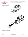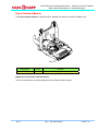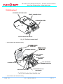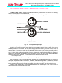
1
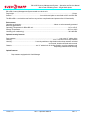
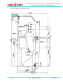
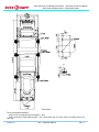
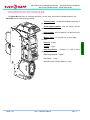
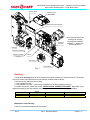
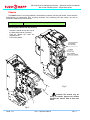
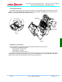
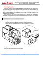
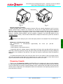
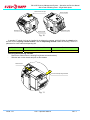
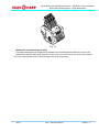
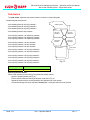
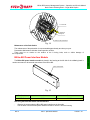
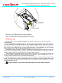
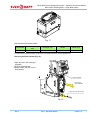
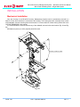
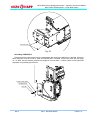
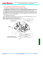
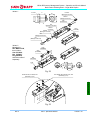
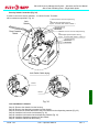
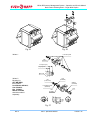
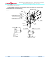
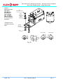
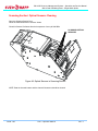
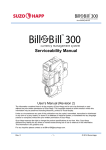
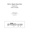
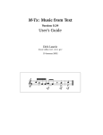
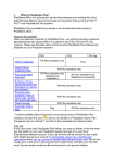
Bill-to-Bill Currency Management System – Operation and Service Manual Bulk Loader Validating Head – Single Width Option Bill-to-Bill Currency Management System With Bulk Loader Validating Head Single width option Operation and Service Manual Part 1. Operation Manual Rev.2 Part 1. Operation Manual PAGE 1-1 Bill-to-Bill Currency Management System – Operation and Service Manual Bulk Loader Validating Head – Single Width Option Table of Contents General description.............................................................................................................................................. 3 General specifications ......................................................................................................................................... 4 Outline drawings .................................................................................................................................................. 7 Description of modules ...................................................................................................................................... 10 Housing ................................................................................................................................................... 11 Chassis.................................................................................................................................................... 12 Recycling Cassette.................................................................................................................................. 14 Dispensing Cassette ............................................................................................................................... 15 Path Switch ............................................................................................................................................. 18 Bill-to-Bill Power Interface Module .......................................................................................................... 19 Drop Cassette ......................................................................................................................................... 20 Power Interface Module .......................................................................................................................... 23 Validating head........................................................................................................................................ 24 Device operation - General principle ................................................................................................................. 25 Device operation – STACK HANDLING.................................................................................................. 26 Device operation – THE NOTE FLOW.................................................................................................... 27 Numbering system............................................................................................................................................. 29 Installation.......................................................................................................................................................... 30 Mechanical installation ............................................................................................................................ 30 Security features (locks and security switches) ...................................................................................... 32 Power and interface connection ........................................................................................................................ 39 Interface description ................................................................................................................................ 39 Power and Interface cables specification................................................................................................ 39 Operating control ............................................................................................................................................... 40 Switch settings ........................................................................................................................................ 40 Errors and Troubleshooting ............................................................................................................................... 42 Application settings ................................................................................................................................. 44 Maintenance & SERVICE .................................................................................................................................. 47 Front Channel’ Optical Sensors Cleaning ............................................................................................... 47 Scanning Section’ Optical Sensors Cleaning.......................................................................................... 48 Contacts:............................................................................................................................................................ 49 Approval of Changes ......................................................................................................................................... 50 PAGE 1-2 Part 1. Operation Manual Rev. 2 Bill-to-Bill Currency Management System – Operation and Service Manual Bulk Loader Validating Head – Single Width Option The Bill-to-Bill Currency Management System is an automatic money-handling device that provides the following features: 1) Validating bills (any country, sizes as specified). Validated bills are distributed between three recycling cassettes and one lockable-removable drop cassette. A maximum of three denominations may be directed to the recycling cassettes, while the rest of the bill denominations will be directed to the drop cassette. Bills may be presented to the device as single notes or as stacks of up to 25 bills at once. 2) Dispensing bills. Bills housed in the recycling cassettes can be bundled and dispensed as change to a customer (up to twenty bills at a time). 3) Unloading bills. Bills from the recycling cassettes can be moved into the drop cassette. The Bill-to-Bill can be programmed to operate in different modes. For example, bill denominations may be designated for each recycling cassette; choice of escrow settings may be specified, etc. Those settings cn be changed from a host controller via interface. For more information about updating the software of the Bill-to-Bill, please see the OPERATING CONTROL section in this Manual. Rev.2 Part 1. Operation Manual PAGE 1-3 GENERAL DESCRIPTION GENERAL DESCRIPTION Bill-to-Bill Currency Management System – Operation and Service Manual Bulk Loader Validating Head – Single Width Option GENERAL SPECIFICATIONS *Bulk loader head does not support bill aligning. Only same width country(ies) allowed. Barcoded Coupon Specifications: Encoding standard………………………….…….............................….ANSI/AIM BC2-1995, Uniform Symbology Specification – Interleaved 2 of 5 Narrow bar width, in mm………………………..............................……..…….………………………..…..0.5 to 0.6 Wide/Narrow bar ratio………………………….............................…………….……………………….…………..3:1 Number of characters…………………………………….............................….…………………….…………6 to 18 PSC (Print Contrast Signal) value ………………………..................................……………………..………0.6 min Bill storage: Number of recycling cassettes……………………………….............................…………………………………….3 Number of drop cassettes…………………………………….............................…………………………………….1 Recycling cassette capacity.………….….................................……….…80 to 110 bills depending on bill length Drop cassette capacity (new bills)……………................................……………………………………….1000 bills Dispensing ability………………………………………..……...............................bundles up to 20 bills at a time Multi-escrow mode Single dispensing…………………………….……………….……………..….............................……..up to 20 bills Several dispensing attempts……….......................................………up to 80 - 110 bills depending on bill length Processing time, in seconds: Total processing time in flow mode (from stack into recycling cassette, best case scenario)…………………1.2 Total time to accept one bill to drop cassette………………………………………….............................. 3.5 to 6 Total time to issue change of 1 bill……….……………………………………………………..................................3 Total time to issue change of 20 bills ………..……………...……………….............................………………… 26 Dispensing speed………………………………..………..............................…...….……1.4 second per bill, max. Firmware updates options: Standard…………………………....……….……………….………..........Crane Payment Solutions Memory Stick Network….………………..............................…….………………………….. Download mode in CCNET protocol External Interfaces: Standard…………………………....……….…….…...............................……..…Bi-directional EIA-232C (RS232) Protocol….…………………………………….…………………...………………... CCNET Power consumption: Operating voltage……………………………….....…………..........................………….……………..…… 24 V DC Current, standby………………………………………….…………….............................……………..………..0.7 A Current, operating mode………………………………………………….…................................…2.7 A (5 A peak) Dimensions (W x H x D)………………………….....……………….............................……..163 x 612 x 434 mm PAGE 1-4 Part 1. Operation Manual Rev. 2 GENERAL SPECIFICATIONS Acceptance: Bills………..………………………………….……………...........stacks of up to 25 bills, lengthwise in 4 directions Barcoded coupons…......………………………………………..............................……..………..two ways, face up Validation rate………………………………….…..................................………96% or higher on first bill insertion Width of bill, in mm*..………………………..................................……………………..………………from 62 to 82 Maximum length of bill, in mm…………….................................………………………..………………………..172 Minimum length of bill, in mm………….................................……………………………………………………..124 Bill-to-Bill Currency Management System – Operation and Service Manual Bulk Loader Validating Head – Single Width Option Weight .....……....………….…………….…………..............................…………………...………….………17.8 kg Approvals: Safety Standards for Coin and Currency Changers and Actuators - Component……………...............................…………..UL 756 FCC Compliance Radiated Emissions from Unintentional Radiators (digital devices) FCC Part 15, Subpart B 15.109a Class B CE Compliance………………………………………..............................……Information Technology Equipment Electromagnetic Compatibility (EMC) Conformity to the Following Standards: CISPR 22:2003 +A1:2004 / EN 55022:2003 Class A - Class A Limits for RF disturbance characteristics of Information Technology Equipment CISPR 24:1997 / EN 55024:1998 +A1:2001 & + A2:2003 Immunity Characteristics – Limits and Methods of Measurements Vibrations, Drop and Shock resistance: Vibrations (sinusoidal) IEC 60068-2-6 Fc: 1995 vibration acceleration amplitude………...........................…………………………………………….. а= 12 m/sec2 bandwidth……………………………………………………..............................……………………. F = 10...200 Hz sweep rate……………………………………………………………..................................... one octave per minute vibration acceleration amplitude ………………………………………………….........................… а= 19,8 m/sec2 bandwidth……………………………………………………….............................…………………. F = 10... 500 Hz sweep rate………………………………………………….................................…………… one octave per minute Endurance at random vibration wide band testing within F = 10. . .200 Hz at 12 m/s2 mean-square acceleration amplitude and number of loading cycles n = 10 е-7 Control method: Bill-to-BillTM operation was continuously controlled by means of the bill loading and unloading. No malfunction or stoppages were registered in the Bill-to-BillTM operation. Mechanical Shocks Shock endurance at shock testing (Shock: IEC 60068-2-27 Ea: 1987; Bump: IEC 60068-2-29 Eb: 1987): shock repetition frequency……………………………………..............................………..……. F = 80 shock / min acceleration amplitude ………………………………………………...............................……………………30 m/s2 duration ………………………………………………………………..…………................................Т=10...12 msec number of shocks………………………………………………………………….............................……………2000 Control method: Bill-to-BillTM operation was continuously controlled by means of the bill loading and unloading. No malfunction or stoppages were registered in the Bill-to-BillTM operation. Free Fall IEC 60068-2-32 Ed: 1975 Test Conditions: Rev.2 Part 1. Operation Manual PAGE 1-5 Bill-to-Bill Currency Management System – Operation and Service Manual Bulk Loader Validating Head – Single Width Option Bill to Bill Currency Management System tested as a whole unit. Drop height ………………………..……………………………….............................……..…………………..50 mm Surface………………………...............................……3 mm thick steel plate on wood bed at 20C and 58% RH The Bill-to-BillTM survived the test free from any serious complications and preserved its full functionality. Environment: Operating environment…..…………….............................……...……………Indoor or environmentally protected stationary applications Operating Temperature for Bill-to-Bill unit……………….............................…………..……………..0C to +50C Storage Temperature……………………………………………….............................…………..…..-30C to +60C Humidity (non-condensing)………………………….............................……………….……..………..30%-90%RH Optional security features: Drop cassette……………………………………….................................………………one or two ¾” tubular locks Housing………………………………………….................................…….…one ¾” tubular lock for drop cassette Housing……………..............................………2 security switches to signal alarm when drop cassette unlocked or removed; chassis unlocked and removed Chassis…….................................……………..one ¾” tubular lock for locking chassis, recycling cassettes and dispensing cassette inside housing Optinal features: Drop cassette equipped with Cash Manager PAGE 1-6 Part 1. Operation Manual Rev. 2 Bill-to-Bill Currency Management System – Operation and Service Manual Bulk Loader Validating Head – Single Width Option OUTLINE DRAWINGS Side view Rev.2 Part 1. Operation Manual PAGE 1-7 Bill-to-Bill Currency Management System – Operation and Service Manual Bulk Loader Validating Head – Single Width Option Front view The recommended installation: Bottom must be supported by mounting pin – qty 2 Side mounting by metal fasteners (M5 – Qty 3 each side) with your own version of bracket from left or right side PAGE 1-8 Part 1. Operation Manual Rev. 2 Bill-to-Bill Currency Management System – Operation and Service Manual Bulk Loader Validating Head – Single Width Option Installation View GOOD Installation Side Bracket Poor Installation Bill to Bill Bill to Bill Base plate on the bottom √ Side Mounting and Mounting Pin on the bottom Bill to Bill Flat base plate on the bottom. This is not all recommended Side Bracket Side Bracket Bill to Bill Base plate on the bottom √ Side Mounting and Mounting Pin on the bottom Bill to Bill Side Mounting and flat base plate on the bottom. This is not all recommended Side Bracket Side Bracket Bill to Bill Base plate on the bottom √ Side Mounting on Both Side and Mounting Pin on the bottom Rev.2 Side Mounting and flat base plate on the bottom. This is not all recommended Part 1. Operation Manual PAGE 1-9 Bill-to-Bill Currency Management System – Operation and Service Manual Bulk Loader Validating Head – Single Width Option DESCRIPTION OF MODULES The Bill-to-Bill was built on modularity principles, just like other front load bill validator products. The Bill-to-Bill consist of the following modules: Validating Head – accepts and validates legitimacy of bill Power Interface Module - Only one variety may be used with the B2B Drop Cassette - Secure Cashbox, it is referred to as a “cassette” Memory Card - is universal for all Suzo-Happ products Chassis – 1 type Recycling Module – Consists of a total of three recycling cassettes Dispensing Cassette – 2 types Path Switch – 1 type Bill-to-Bill Power Interface Module – 1 type PAGE 1-10 Part 1. Operation Manual Rev. 2 DRAWINGS Housing – 2 types Bill-to-Bill Currency Management System – Operation and Service Manual Bulk Loader Validating Head – Single Width Option Memory Card Validating Head with Loader B2B Power Interface Module Dispensing Cassette All modules (except for the housing) can be easy removed and replaced if needed (i.e.: should a bill become jammed). Housing MFL Power Interface Recycling Cassette (3 pcs.) Chassis Path Switch Drop Cassette Fig. 1 Housing The Bill-to-Bill housing carries all of the modules and cables necessary for interconnections. The housing is the only module in the Bill-to-Bill that is permanently installed inside a cabinet. There are security switches in the housing: 1. “drop cassette removal”, 2. “drop cassette lock open”, (if the locking mechanism for the drop cassette is present), For switch connection, please refer to the “INSTALLATION. SECURITY FEATURES”. Depending on the supporting bracket for the drop cassette, the following implementations of the housing are available: Part Number BBHR3110 BBHR3512 Bezels Plastic Plastic Drop Cassette size 1000 1000 Locking mechanism NO YES Maintenance of the Housing. There is no procedure designated for this module. Rev.2 Part 1. Operation Manual PAGE 1-11 Bill-to-Bill Currency Management System – Operation and Service Manual Bulk Loader Validating Head – Single Width Option Chassis The chassis carries 3 recycling cassettes, one dispensing cassette, and one path switch. It also has drive arrangements—for transporting bills, recycling cassettes, and positioning the path switch—as well as connection cables and a local controller. Part Number BBCR0110 Number of Recycling Cassettes 3 Removing the Chassis from the Housing Unlock the tubular lock at the front of the dispensing module (if present) Push the release bar under the validating head Pull out the chassis 1. PUSH THE BAR TO RELEASE THE CHASSIS HANDLE 2. PULL OUT THE CHASSIS USING THE HANDLE Fig. 2 Caution! The chassis may be heavy to handle! Support the module beneath the chassis with at least one hand. Fig. 3 PAGE 1-12 Part 1. Operation Manual Rev. 2 Bill-to-Bill Currency Management System – Operation and Service Manual Bulk Loader Validating Head – Single Width Option Accessing the Bill Path: Press either release button and pull open the machine. The gas spring supports the chassis in the opened position. The opened chassis also allows access to the path switch. The chassis can be opened with, or without, the recycling and dispensing cassettes present. Push release button to open the Chassis Path Switch Optical sensors MODULES Fig. 4 Fig. 5 Maintenance of the Chassis The maintenance of the chassis is recommended approximately two times per year. The preventative maintenance includes: visual inspection of timing belts visual inspection of gears visual inspection of optical sensors There must not be any cracks on the surface of the four timing belts; no dust or dirt on the surface of the optical sensors (6 sensors at each guide, for a total of 24 sensors), and no visible damage of the gears. Optical sensors should be cleaned with a soft cloth and isopropyl alcohol. Rev.2 Part 1. Operation Manual PAGE 1-13 Bill-to-Bill Currency Management System – Operation and Service Manual Bulk Loader Validating Head – Single Width Option Recycling Cassette The Bill-to-Bill carries up to three recycling cassettes, which operate identically. Built with flexibility in mind, the user can program which bill denominations will be used in each of the recycling cassettes. (For Software update instructions, please read the chapter entitled “SETTING BILL DENOMINATION FOR RECYCLING CASSETTE”, below.) The maximum storage capacity of each cassette ranges from 80 to 110 bills. The exact number of bills that can be stored is dependent upon the bill length: the shorter the bill, the higher the number of bills that can be placed inside the cassette. A flash memory inside each recycling cassette stores information on the number, and denomination of bills housed in the cassette. The flash memory prevents operation errors from occurring, i.e.: when a cassette is installed in a random position in the Bill-to-Bill. Part Number BBRR0110 Bill storage capacity 80 - 110 Removing the Cassette: Remove the chassis from the Bill-to-Bill housing first (see section entitled “chassis”) Slide the latch on the chassis (each cassette has its own latch) and pull out the cassette Slide the latch Pull out the Cassette Fig. 6 Fig. 7 Opening the Cassette: Pull the metal latch, and open the front cover of the cassette. PAGE 1-14 Part 1. Operation Manual Rev. 2 Bill-to-Bill Currency Management System – Operation and Service Manual Bulk Loader Validating Head – Single Width Option Open the cover Plastic handle Pull the latch Fig. 8 Fig. 9 Manually Unloading Cassettes: Rotate the plastic knob in counter-clockwise direction. Bills are manually dispensed one bill at a time. Should a jammed bill be located in the entrance slot, this bill can be easily removed without adversely affecting the later operation of the cassette. Please note: manually unloading bills will reduce the number of bills in the cassette, without changing the number of bills in flash memory. It is strongly recommended to perform a complete unload operation, after the cassette is replaced in the Bill-to-Bill (please see the “Unloading Options” section). This will allow the Bill-to-Bill to readjust the flash memory when the cassette is operational again. Caution. Do not attempt to pull out the white tapes present in the cassette! This could damage the Maintenance of the Recycling Cassette The maintenance is recommended includes: - visual inspection of tapes - visual inspection of input optical sensors approximately two times per year and A mechanism within the cassette keeps the tapes tight at all times, which provides sufficient support for stored bills. Should any tape begin to sag, this can be easily corrected during service by simply rotating the plastic knob on the cassette in any direction. This action will cause the mechanism inside the cassette to retighten. For optimal performance, there must not be any dust or dirt on the surface of the input optical sensors. (There are two sensors at each side of the entrance slot, for a total of four sensors.) Input optical sensors may be cleaned with a soft cloth and isopropyl alcohol once the front cover is open. Dispensing Cassette There is only one dispensing cassette in the Bill-to-Bill unit. In contrast to the three recycling cassettes, the dispensing cassette has a permanent position in the chassis. The dispensing cassette can form a bundle of up to 20 bills. Bills from all three recycling cassettes can be combined into one bundle. Should more than 20 bills need to be dispensed, then subsequent bundles will be delivered to the dispensing cassette once the previous bundle is removed. Rev.2 Part 1. Operation Manual PAGE 1-15 MODULES cassette! Bill-to-Bill Currency Management System – Operation and Service Manual Bulk Loader Validating Head – Single Width Option Slide the latch to open Entering slot Service keypad Dispensing slot Plastic handle Fig. 10 A standard ¾” tubular lock can be installed in the dispensing cassette, which will allow the chassis to be secured to the recycling cassette module, and the dispensing cassette inside the housing. There is a placement for a lock under the dispensing slot. Part Number Maximal bundle size, bills Bezels BBDR0110 20 Plastic Removing the Dispensing Cassette: Remove the chassis from the housing first (please see section above) Slide the latch on the chassis and pull out the cassette Slide the latch Pull out the Dispensing Cassette Fig. 11 PAGE 1-16 Part 1. Operation Manual Rev. 2 Bill-to-Bill Currency Management System – Operation and Service Manual Bulk Loader Validating Head – Single Width Option Fig. 12 Maintenance of the Dispensing Cassette: Preventative Maintenance of the dispensing cassette is recommended approximately two times per year. Maintenance should include visual inspection of belts. Also, there must not be any cracks on the surface of any of the 8 timing belts, and no visible damage of any of the components. Rev.2 Part 1. Operation Manual PAGE 1-17 Bill-to-Bill Currency Management System – Operation and Service Manual Bulk Loader Validating Head – Single Width Option Path Switch The path switch organizes connections between modules via various bill paths. Possible bill path directions are: from validating head to recycling cassette 1 from validating head to recycling cassette 2 from validating head to recycling cassette 3 from validating head to drop cassette from recycling cassette 1 to dispensing cassette from recycling cassette 2 to dispensing cassette from recycling cassette 3 to dispensing cassette from recycling cassette 1 to drop cassette from recycling cassette 2 to drop cassette from recycling cassette 3 to drop cassette Validating Head Recycling Cassette 1 Recycling Cassette 2 Dispensing Cassette Recycling Cassette 3 Drop Cassette Path Switch from recycling cassette 1 to recycling cassette 2 from recycling cassette 1 to recycling cassette 3 from recycling cassette 2 to recycling cassette 1 from recycling cassette 2 to recycling cassette 3 from recycling cassette 3 to recycling cassette 1 from recycling cassette 3 to recycling cassette 2 Part Number Number of connected paths BBSR0110 6 Fig. 13 Removing the Path Switch: Remove the chassis from the housing first (please see section above) Open the chassis (please see Fig. 6) Pull the tab and rotate the bearing 90 degrees, as shown in Fig 15. Repeat the action with the second bearing at the opposite side of the chassis Once both bearings have been released, carefully pull out the path switch from the chassis PAGE 1-18 Part 1. Operation Manual Rev. 2 Bill-to-Bill Currency Management System – Operation and Service Manual Bulk Loader Validating Head – Single Width Option 1. Pull the tab 2. Rotate the bearing 90° 3. Remove the Path Switch Fig. 14 Maintenance of the Path Switch: Bill-to-Bill Power Interface Module The Bill-to-Bill power interface module is placed in the housing at the left side of the validating head. It carries connectors for all external connections to the Bill-to-Bill. Power and interface Fig. 15 Part Number Interface Power BBPR5713 RS232 24V DC Removing the Bill-to-Bill Power Interface Module: Remove the screw under the Bill-to-Bill power interface at the front side Pull the latch of the Bill-to-Bill power interface module to remove it from the housing Rev.2 Part 1. Operation Manual PAGE 1-19 MODULES The maintenance of the path switch is recommended approximately two times per year. Preventative Maintenance includes visual inspection of belts. There must be no cracks on the surface of the 8 timing belts, and no visible damage of the components. Bill-to-Bill Currency Management System – Operation and Service Manual Bulk Loader Validating Head – Single Width Option 2. Pull the latch 1. Remove screw Fig. 16 Maintenance of the Bill-to-Bill Power Interface Module: There is no maintenance procedure designated for this module. Drop Cassette The Bill-to-Bill can utilize one drop cassette; this is the same cassette used in other front load bill validator models. The drop cassette stores validated bills and barcoded coupons and holds them in a stacked formation. The drop cassette has a stacking mechanism, and is typically equipped with a plastic lock. Users are encouraged to replace the plastic lock with a regular metal one. Users also have a choice between one lock—or two locks for added security. A locking mechanism allows for the installation of a user’s security locks (specifically, one or two 3/4” tubular locks measuring 11/16”±1/16” or 11/8”±1/16”). The capacity of the drop cassette is 1000 bills. Street grade bills require more space and as a result, may lessen the overall capacity. The drop cassette is supplied with a foldable handle, but where space inside the machine is limited, a premium drop cassette may be ordered without a handle. The drop cassette can store bills from 62 to 82 mm wide, and from 140 to 172 mm long. For bills from 125 to 150 mm in length, a modified drop cassette may be ordered. However, when accepted bill are 125 to 172 mm long, the drop cassette for 140-172 mm range must be chosen. The drop cassette may be ordered with mounting parts for installation of a Touch Memory (Dallas Chip) option. The Dallas Chip is located in the cassette housing. The proper type of power interface module must be ordered in order to communicate with the Dallas Chip. Drop cassette selection is dependent on which housing is present in the unit. The Drop Cassette is not included with the Bill-to-Bill and must be ordered separately. PAGE 1-20 Part 1. Operation Manual Rev. 2 Bill-to-Bill Currency Management System – Operation and Service Manual Bulk Loader Validating Head – Single Width Option Fig. 17 Drop Cassette with foldable handle Part Number FLCR603 Cassette capacity, bills 1000 Bill length, mm Handle Dallas Chip 140 to 172 Foldable No For other drop cassettes please contact the Suzo-Happ Customer Service department. Removing the Drop Cassette (Fig. 19): 1.Open the lock in the housing (if equipped) 2.Push the release button 3.Grasp handle and pull out the drop cassette 2. Push the button 3. Pull out the Drop Cassette 1. Open the Lock with the Key Fig. 19 Rev.2 Part 1. Operation Manual PAGE 1-21 Bill-to-Bill Currency Management System – Operation and Service Manual Bulk Loader Validating Head – Single Width Option Collecting bills: 1. Unlock 1 (or 2 locks) and open the cover Fig. 20 2. Remove bills Fig. 21 Maintenance of the Drop Cassette: There is no maintenance procedure designated for the drop cassette. PAGE 1-22 Part 1. Operation Manual Rev. 2 Bill-to-Bill Currency Management System – Operation and Service Manual Bulk Loader Validating Head – Single Width Option Power Interface Module The Power Interface module for the Bill-to-Bill is adopted from other front load bill validator units. Fig. 22 Part Number Power Interface FLPR5711 24 VDC CCNET (single slave mode) Maintenance of the Power Interface Module: There is no maintenance procedure designated for the Power Interface module. Rev.2 Part 1. Operation Manual PAGE 1-23 Bill-to-Bill Currency Management System – Operation and Service Manual Bulk Loader Validating Head – Single Width Option Validating head SCANNING SECTION DOOR FRONT CHANNEL DOOR INTEGRATED BEZEL STATUS INDICATOR LIGHTS Fig. 23. The Bulk Loader Head* * - minor features are omitted for clarity SCANNING SENSORS CENTRAL CHANNEL SENSORS FRONT CHANNEL SENSORS COIN, WATER AND DEBRIS DRAIN GRID PUSHING ROLLER SEPARATING ROLLERS HEAD REMOVAL FLAP AND HANDLE Fig. 24. Bulk Loader Head detailed view* * - minor features are omitted for clarity PAGE 1-24 Part 1. Operation Manual Rev. 2 Bill-to-Bill Currency Management System – Operation and Service Manual Bulk Loader Validating Head – Single Width Option DEVICE OPERATION - GENERAL PRINCIPLE The Bulk Loader Head is intended to provide performance gains compared to standard bill validating heads when processing multi-bill transactions. Separation of bills from stack is based on friction difference, as shown in Figure 25. ROLLER A - FEEDING FRICTION ZONE 1 FRICTION ZONE 3 FRICTION ZONE 2 ROLLER B - SEPARATING SPRING LOAD Fig. 25. The separation principle According to Figure 25 the stack of notes is fed into the separation group of rollers A and B. The A rollers are always rotating in one direction, with the torque staying relatively the same. The friction in zone 1 (roller A and a note) is selected to be greater than friction in zone 2 (between notes). This is guaranteed by roller A material choice. The friction in zone 3 is also grater than friction in zone 2, but normally less than friction in zone 1. Under ideal conditions, the whole system is maintained in quasi-equilibrium with roller B stalled, allowing only one note to propagate through the separation group. In real world, many factors add and the separation may become unreliable. To compensate for that, two approaches are utilized: roller B torque control; sensors to detect multiple notes exiting the separation group. Roller B torque is not only controlled at time of separation, but also calibrated periodically, e.g. at system startup, to compensate for dirt accumulation, roller wear and material degradation. Calibration is achieved with roller A rotating with constant speed and torque, while roller B torque is gradually increased. When the torque becomes strong enough to disrupt even rotation of the roller B by roller A, the torque value is saved. The saved value is later used in conjunction with the double-note sensor output. If the sensor indicates a double take, torque is increased, and vice versa. Rev.2 Part 1. Operation Manual PAGE 1-25 Bill-to-Bill Currency Management System – Operation and Service Manual Bulk Loader Validating Head – Single Width Option Device operation – STACK HANDLING The generalized stack processing is illustrated in Figure 26. There’s no try limit shown in the flowchart, but it is present in a real system and is normally set to 3 full attempts. start 2 1 feed the stack into separation group with pushing roller wait until first note emerges from rollers Yes start separation group No start separation group wait for a note to emerge or timeout transport the note to scanning area and start scanning wait until the note leaves rollers is there a note in separation group? any note emerged? Yes No 1 stop separation group continue scan until the internote gap is wide enough 2 Fig. 26. Generalized stack processing The arrows illustrate 3 distinct routes the stack processing can take: GREEN route – the fast flow, can only occur after the first note is taken; BLUE route – the partial take, can only occur after the first note is taken, take in case a following note failed to enter the rollers; RED route – the full take, occurs on a first note in a stack and also in case the partial take has failed. PAGE 1-26 Part 1. Operation Manual Rev. 2 Bill-to-Bill Currency Management System – Operation and Service Manual Bulk Loader Validating Head – Single Width Option Device operation – THE NOTE FLOW In case of fast flow, there is more than one note traveling the bill path at the same time, as illustrated in Figure 27. This is a substantial difference from the standard validating head. ESCROW PLANE 1 2 BULK LOADER HEAD 3 CASSETTE 1 CASSETTE 2 SWITCH CASSETTE 3 CHASSIS Fig. 27. The note flow The notes, shown in blue, all share the same path. While note 1 is separated from the stack note 2 is scanned and note 3 is stacked. The whole flow stops when note 2 trailing edge reaches the escrow plane. To prevent jams, note 3 trailing edge must be at least in the switch at this point. In case of a fast flow, the note 1 leading edge will be entering the scanning area at the same time. If the fast flow conditions are not met, the gap between notes 1 and 2 increases, bringing down the device performance. In most cases this happens with poorly aligned stack or poor note condition. While processing notes, the Bulk Loader Head is running a state machine. The state machine flowchart is shown Fig. 28. Rev.2 Part 1. Operation Manual PAGE 1-27 Bill-to-Bill Currency Management System – Operation and Service Manual Bulk Loader Validating Head – Single Width Option note taking is there a note out of separation group? No No is there a note in escrow? device in IDLING or switches to idling; bezel in GREEN runway wait until note or stack inserted Yes Yes device goes into ACCEPTING, LEDs switch to red is note recognized? repeat while first note emerges from separation rollers, up to 3 attempts is separation successfull? Yes No No Yes wait until notes are removed switch to STACKING, start packing switch to REJECTING, start moving note to dispenser next note processing start in parallel with stacking next note processing goes in parallel with moving to dispenser wait for stacking to complete wait for note to be removed from dispenser post credit message onto the que Fig. 28. Note processing state machine. The device state names in Figure 28 (e.g. IDLING) are internal states and may or may not correspond to the states reported over the communication protocol. Many similarities can be observed between Figures 8 and 6. PAGE 1-28 Part 1. Operation Manual Rev. 2 Bill-to-Bill Currency Management System – Operation and Service Manual Bulk Loader Validating Head – Single Width Option NUMBERING SYSTEM Depending on currency, interface and available features, Users can choose the Bill-to-Bill that best matches their needs. Complete part numbers for the Bill-to-Bill consist of two parts: a hardware part number and a software part number. The part number looks like this: BBR 0101 US1701 01 Software part number Hardware part number Prefix The prefix defines the device class. In this instance, “BB” means Bill-to-Bill Currency Management System. The hardware part number reflects the contents of the Bill-to-Bill (ie. the particular combination of modules). The software part number reflects the country (currency), communication protocol and Chassis’ software version. Rev.2 Part 1. Operation Manual PAGE 1-29 Bill-to-Bill Currency Management System – Operation and Service Manual Bulk Loader Validating Head – Single Width Option INSTALLATION Mechanical installation Only the Housing of the Bill-to-Bill Currency Management System must be permanently secured in a cabinet. All the other modules are connected to the housing. The housing has three mounting holes at each of the sidewalls, and two mounting holes at the bottom. For exact locations of these holes, please refer to the OUTLINE DRAWINGS in this manual. It is recommended to use three holes at any of the sidewalls, and two holes at the bottom (Fig. 29 and Fig. 30). M5 fasteners (metric) or 10-24 (imperial) should be used. Screws or bolts from inside Fig. 29 PAGE 1-30 Part 1. Operation Manual Rev. 2 Bill-to-Bill Currency Management System – Operation and Service Manual Bulk Loader Validating Head – Single Width Option Nuts from inside Fig. 30 Grounding of BBHR3513 Protective-earth ground terminal must be connected to the automat grounding bus or terminal. Protective earth connection must be made by cable OPT-MKSM-GND or another cooper wire cable with wire gage 14…12 AWG. Use the shortest, practical wire length but no more than 1.5 meters. Refer to local codes and regulations for grounding requirements. Protective Earth Cable Lock Washer M4 Screw M4 Rev.2 Part 1. Operation Manual PAGE 1-31 Bill-to-Bill Currency Management System – Operation and Service Manual Bulk Loader Validating Head – Single Width Option Security features (locks and security switches) The Bill-to-Bill Currency Management System has several security features. The drop cassette can be locked with one or two ¾” tubular locks. The drop cassette can be also locked to the housing with a ¾” tubular lock. There can be two security switches: one detects the presence of the drop cassette in the housing, and another detects that the housing lock is secured in “locked” position. The chassis within the recycling and dispensing cassettes can be locked in the housing with a ¾” tubular lock, positioned 5/8” from the mounting surface to a latch. The provision for the lock is located in the dispensing cassette. Neither recycling cassettes nor dispensing cassettes can be removed from the chassis, until the cassis is not removed from the housing. Lock Installation in the Housing: Step #1. Remove the screw and lock washer from the lock cover. DO NOT DISCARD! (Please see FIG. 31.) Step #2. Remove and discard the washer and spacer (Fig. 31). Step #3. Install the lock and parts, as shown in Fig. 32. Step #4. Install the cover, screw and lock washer that were removed in Step #1 (please see Fig.33) Lock Washer M3, Internal Tooth, Zinc (8203002) Screw M3x16, Pan Head, Zinc (8201955) (3 pcs.) Cover Ass'y (0100204) Spacer #10x0.5" FT SP100 "SPIROL" (8208998) Parts for transportation only, to be removed when lock installed Steel Flat Washer SPAENAUR No 656-057 (8203999) PAGE 1-32 Part 1. Operation Manual INSTALLATION Fig. 31 Rev. 2 Bill-to-Bill Currency Management System – Operation and Service Manual Bulk Loader Validating Head – Single Width Option Variant 1 12.7max A Hex Nut (Belongs to the lock) 25.4 22.2max 22 A=from 5 8 " to 1 1 8 " Washer (Belongs to the lock) Cam (5110049-01) Nut (Belongs to the lock) Washer (5110035) Cover (0100186) Washer (Belongs to the lock) Lock (Belongs to the lock) Key (Belongs to the lock) Variant 2 Mounting kit OPT-MKFL-FLH2, that includes : Cam 5110099; Nut 5310021; Plug 5206036, should be ordered separately. Plug (5206036) Cam (5110099) Nut (5310021) 3 O22 Lock 19.5 Fig. 32 Lock Washer M3, Internal Tooth, Zinc (8203002) (3 pcs.) INSTALLATION Screw M3x16, Pan Head, Zinc (8201955) (3 pcs.) Fig. 33 Rev.2 Part 1. Operation Manual PAGE 1-33 Bill-to-Bill Currency Management System – Operation and Service Manual Bulk Loader Validating Head – Single Width Option Security Switch Connection (Fig. 34): In order to connect to security switches, .110 Quick Connect Terminals will be needed, as specified in Fig. 34. .110 Quick Connect Terminal, Flag Housing, e.g. AMP Flag Style Receptacle Housing, Style E, .110 Series, AMP Part No. 360040-1 Lock Switch Common terminal NO terminal NC terminal Drop Cassette Switch 110 Quick Connect Terminal, Straight Housing, e.g. AMP Straight Style Receptacle Housing, Style C, .110 Series, AMP Part No. 1-480417-0 Common terminal NO terminal NC terminal Lock Switch Cable laying INSTALLATION Variant 1 Variant 2 Fig. 34 Lock Installation in Chassis: Step #1. Remove the chassis from the housing Step #2. Remove the dispensing cassette from the chassis Step #3. Unscrew two screws and remove the lock bracket from the dispensing cassette (Fig. 35) Step #4. Install the lock into the lock bracket (Fig. 36) Step #5. Install the lock bracket into the dispensing cassette (Fig. 37) Step #6. Install the dispensing cassette into the chassis Step #7. Install the chassis into the housing PAGE 1-34 Part 1. Operation Manual Rev. 2 Bill-to-Bill Currency Management System – Operation and Service Manual Bulk Loader Validating Head – Single Width Option Fig. 35 Fig. 36 Variant 1 Lock and its parts Cam (5106018) 15.875 [3/4"] only 6.35 [1/4"] max O22.2 max Cam (5106033) Nut (Lock's Part) Washer (5310022) Lock Washer M10 (8203012) Lock O22 max Nut (5310021) 3 Variant 2 Mounting kit OPT-MK-BBD1, that includes : Lock Washer 8203012; Cam 5106033; Nut 5310021; Washer 5310022, should be ordered separately. 19.5 Fig. 37 Rev.2 Part 1. Operation Manual PAGE 1-35 Bill-to-Bill Currency Management System – Operation and Service Manual Bulk Loader Validating Head – Single Width Option Lock and its parts Cam (5106018) 15.875 [5/8"] only 6.35 [1/4"] max Ø22.2 max Fig. 38 Fig. 39 PAGE 1-36 Part 1. Operation Manual Rev. 2 Bill-to-Bill Currency Management System – Operation and Service Manual Bulk Loader Validating Head – Single Width Option Lock Installation in Drop Cassette In order to install the security locks in the drop cassette, open the drop cassette cover, remove the plastic lock and plug, and follow the diagrams as below. Belonging to the lock Hex Nut Variant 1 Washer Cam (5110032) *Washer (5110034-01) (Only for installation of the lock A = 5/8 ") *Washer (5110034) (Only for installation of the lock A = 5/8 ") Nut Cassette Washer Cover Lock 12.7max A DIA22.2max Washers (1-2 pcs.) (5110035) Rev.2 A=1116"±116" or A=118"±116" Washers (5110034) and/or (5110034-01) B Adjust size B with Washers within 0.6875±0.01" or 1.125±0.01" Part 1. Operation Manual PAGE 1-37 Bill-to-Bill Currency Management System – Operation and Service Manual Bulk Loader Validating Head – Single Width Option Variant 2 Mounting kits (for each lock*) OPT-MK-FLC1, that includes : Cam 5106034; Nut 5310021; Washer 5310022, should be ordered separately. * Cassette may be used with one or two locks. Nut (Belongs to Lock) Cam (5106034) Nut (5310021) Washer (5310022) Lock ° 90 O22 3 Key turn right 90 ° Key turn left 19.5 Fig. 40 PAGE 1-38 Part 1. Operation Manual Rev. 2 Bill-to-Bill Currency Management System – Operation and Service Manual Bulk Loader Validating Head – Single Width Option POWER AND INTERFACE CONNECTION The Bill-to-Bill power interface module has the following external connections: Fig. 41 X2, Molex p/n 43650-1000 (module portion) TERMINAL SIGNAL FUNCTION POWER + 1 POWER (24 V DC) POWER + 2 POWER (24 V DC) POWER 3 POWER (0 V) POWER 4 POWER (0 V) 5 CHASSIS Functional Earth 6 CHASSIS Functional Earth 7 RXD Host serial receive 8 TXD Host serial transmit 9 M-RES Master reset 10 GND Interface common Interface description The Bill-to-Bill interface operates with RS232 levels and under CCNET protocol. A detailed description of the CCNET protocol can be found in the “Crane Payment Solutions NET Interface Manual”. Power and Interface cables specification The lengths of power and interface cables should not exceed 10 meters Power and interface cables do not connect to outdoor communication links and to outdoor DC current lines. As interface cable to use the shielded cable. The shield is connected to pin 6 of connector X2. The shield of another cable end is connected either to the case of Host or to the grounding bus or terminal of the automat near to Host Controller. As power cable to use fourth core cable connected to pins 1, 2, 3 and 4 of connector X2. Each wire section should be not less AWG22. From the direction of the power supply the wires are connected in pairs. Rev.2 Part 1. Operation Manual PAGE 1-39 Bill-to-Bill Currency Management System – Operation and Service Manual Bulk Loader Validating Head – Single Width Option OPERATING CONTROL Switch settings Device configuration is implemented with array of DIP switches, divided into SW1 and SW2 banks. DIP switch banks location is shown in Fig. 42. MEMORY CARD SLOT SW 2 BANK SW 1 BANK Fig. 42. DIP switch array and Memory Card slot Every DIP switch bank is a piano-type switch component on the main control board with switches accessible through the compartment windows. Every bank, if viewed through the window will look similar to what is shown in Figures 43 and 44. The default setting for all switches is “OFF” position. ON 1 2 3 4 5 6 7 8 Fig. 43. SW1 bank simplified view ON 1 2 3 4 Fig. 44. SW2 bank simplified view The DIP switch banks SW1 and SW2 functions are summarized in the tables below: Switch # SW1.1 SW1.2 SW1.3 SW1.4 SW1.5 SW1.6 SW1.7 SW1.8 ON Bill type 0 acceptance disabled Bill type 1 acceptance disabled Bill type 2 acceptance disabled Bill type 3 acceptance disabled Bill type 4 acceptance disabled Bill type 5 acceptance disabled Bill type 6 acceptance disabled Bill type 7 acceptance disabled OFF Bill type 0 acceptance controlled by host Bill type 1 acceptance controlled by host Bill type 2 acceptance controlled by host Bill type 3 acceptance controlled by host Bill type 4 acceptance controlled by host Bill type 5 acceptance controlled by host Bill type 6 acceptance controlled by host Bill type 7 acceptance controlled by host SW1 DIP switch bank functions* PAGE 1-40 Part 1. Operation Manual Rev. 2 Bill-to-Bill Currency Management System – Operation and Service Manual Bulk Loader Validating Head – Single Width Option The DIP switch bank SW1 is always assigned for bill acceptance control. If the bill table for a particular firmware release is shorter than 8 entries, only the relevant switches can be used; other switches from SW1 bank are not used and their setting has no effect. NOTE: If switch setting disables a bill it cannot be enabled over CCNET. If a bill is enabled by switch setting then CCNET has full control of that bill enabled status. * - TBD – to be defined; Switch # SW2.1 SW2.2 SW2.3 SW2.4 ON Acceptance one way face up only High security mode enabled CCNET 19200 bps data rate TBD OFF Four way acceptance High security mode disabled CCNET 9600 bps data rate TBD SW2 DIP switch bank functions* NOTE: CCNET security control is disabled if a switch disables High security mode – setting security bits from CCNET will have no effect in this case. High security mode must be enabled to allow security level control from CCNET. * - TBD – to be defined; Rev.2 Part 1. Operation Manual PAGE 1-41 Bill-to-Bill Currency Management System – Operation and Service Manual Bulk Loader Validating Head – Single Width Option ERRORS AND TROUBLESHOOTING Any error a device encounters is reported, both over the communication protocol and visually with colored blinks on the indicator lights. Under normal operation when a device is ready to accept notes, the indicator lights are in green “runway” mode. Any error will drive the lights either into red or into a series of red or green blinks either on dark or red background The application level blink codes are generated in red on black background. They are summarized in the following table: Status of diagnostic light 1 red flashes on black bkgrd Error description Box is removed or Box sensor failure 2 red flashes on black bkgrd Boot operation error 3 red flashes on black bkgrd Box is full or Box pusher plated drive is too tight, but not stuck 4 red flashes on black bkgrd Box pusher plate is stuck or sensor error 6 red flashes on black bkgrd 7 red flashes on black bkgrd 11 red flashes on black bkgrd Optical sensor failures of any nature Magnetic sensors cannot be tuned into resonance frequency Bills in channel or channel sensors failure 14 red flashes on black bkgrd Verification Software (VS) integrity problem Corrective action verify the Drop Box is fully inserted; if the error persists the Power Interface module may need replacement; verify the card is in secured in place; take the card out and clean the contact pads with soft cloth; reinstall the card; check the Drop Box if it is full and empty it if needed; if error persists the Drop Box may need replacement; verify the Drop Box is fully inserted; if error persists, the Drop Box and/or Power Interface module may need replacement; if error persists the Bulk Loader Head may need service; wait 30 seconds; if error persists or reappears frequently the Bulk Loader Head may need service; verify there’re no bills or bill fragments in the channel; if error persists the Bulk Loader Head may need service; the VS update was not performed – update the VS firmware to a correct version; the main firmware or was upgraded and it is no longer compatible by interface with VS – update the VS firmware to a correct version; if error persists the Bulk Loader Head may need service; * - other values to be defined; Apart from the blink codes, there are many errors reported over the communication protocol. For the Bill-to-Bill chassis errors, please refer to the Bill-to-Bill Currency Management System – Operation and Service Manual Appendix 1 for error definitions. Due to the complex nature of the Bill-to-Bill system, and with the Bulk Loader Head installed in particular, bill jam removal sequences may be far from obvious. The sample decision flowchart in shown in Fig. 45. Please note that manually pulling the notes out of a jam location is risky and the note may be easily torn into pieces. PAGE 1-42 Part 1. Operation Manual Rev. 2 Bill-to-Bill Currency Management System – Operation and Service Manual Bulk Loader Validating Head – Single Width Option jam removal power the device down is a jam suspected between the Bill-to-Bill chassis and the Drop Box? remove the drop box. do not remove the chassis now is there a note protruding down from the chassis? Yes where is the jam? remove the head. do not remove the chassis now remove the note by pulling it down. is a jam suspected between the head and the chassis? where is the jam? Yes is a jam suspected in the head? Yes No No remove the note by pulling it up No is a jam suspected in the Drop Box itself? where is the jam? No where is the jam? Yes remove the chassis, open it and check is there are any notes in the channels remove each cassette and check for notes protruding out open the head doors and remove the jam is there a note protruding out? Yes No No Yes wind the note back into cassette manually place the cassettes back and close the chassis open the drop box and remove the jam reinstall the chassis, the head and the box reinstal the box power the device up end Fig. 45. Jam removal procedure Rev.2 Part 1. Operation Manual PAGE 1-43 Bill-to-Bill Currency Management System – Operation and Service Manual Bulk Loader Validating Head – Single Width Option Application settings The Bill-to-Bill has several internal settings that can be programmed. The settings can be programmed via interface by the host controller only. The following options can be programmed and/or reprogrammed: Designation of bill denomination for each of the recycling cassettes. This setting will be saved in the internal memory of the recycling cassette. Once programmed, the recycling cassette can be placed in any position in the Bill-to-Bill—and will operate with the designated denomination only. The recycling cassette can be programmed for a multi-escrow application. This means that all validated bills will be directed from the validating head into the recycling cassette. This option is useful when more than one bill is inserted during one transaction. Should the User cancel the transaction, all of the same bills will be returned through the dispensing cassette. Should the transaction complete successfully, all bills from the multi-escrow recycling cassette will be reloaded into the drop cassette and/or the other recycling cassettes. This operation will be completed automatically, during the period of time before the next User starts a transaction. When the next User inserts a bill, the reload process will be temporarily paused, and the Bill-toBill will promptly serve the new User. The reload process will recommence between Users. Unloading options. Bills from the recycling cassettes can be reloaded into the drop cassette. This mode can be initiated from the host controller only. Unloading can be done until the recycling cassette is empty, or until the designated number of bills is left in the cassette (“unload level”). Setting up unloading options may be different for each of the recycling cassettes. Upper load limit of bills in recycling cassettes. The Bill-to-Bill will try to replenish all of its recycling cassettes with validated bills. All validated bills will be directed to a recycling cassette with its corresponding denomination. Extra bills will be directed to the drop cassette. The upper load limit for each recycling cassette can be designated and programmed. Software updates The Bill-to-Bill Software consists of Validating Head control software, Validating Head Validation software and Chassis software. Chassis software includes central processor software, cassette software and dispenser software. Validating Head software updates: The Bill-to-Bill Currency Management System is supplied with pre-installed software, according to a User’s order. A “dummy card” is normally placed in the slot indicating the software version. Software updates are recommended whenever new currency is issued, or whenever counterfeit bills appear on the market. Software updates are offered in three options: 1) New software can be ordered with a single-download memory card. The software from the new memory card is downloaded as soon as it is inserted into the slot, and the validating head is powered on. The memory card must be present at all times for the Bill-to-Bill to operate. 2) New software can be ordered with a multi-download memory card. The software supplied through the multi-download memory card allows the Bill-to-Bill to operate even after it is removed from the slot. The memory card can be used for updating the next Bill-to-Bill unit, depending on the number of licenses ordered. Typically a multi-download memory card is issued for a specified number of downloads, and therefore the number of downloads required must be defined in the User’s order. 3) A special memory card can be ordered, which allows the download of new software through the interface connector. This memory card must be present in the validating head at all times. The download can be done via the host controller (and local network). Downloads can also be accomplished with any personal computer. The Bill-to-Bill must be temporarily disconnected from the host controller for this purpose. PAGE 1-44 Part 1. Operation Manual Rev. 2 Bill-to-Bill Currency Management System – Operation and Service Manual Bulk Loader Validating Head – Single Width Option Fig. 46 VALIDATING HEAD SOFTWARE UPDATE PROCEDURES Download Procedure for a Single-download Memory Card: Step 1. Turn Power OFF. Step 2. Lift up the latch under the validating head; and remove the validating head from the housing. Step 3. Remove the card from the slot. (please see Fig. 42). Step 4. Insert the new memory card. (please see Fig. 42), contact pads facing up and away from user. Step 5. Insert the validating head into the housing. Step 6. Turn power ON and wait until the download process is completed. During the download, the status indicator will flash RED-GREEN. Once the download is completed, the unit will initialize and the status light will turn green. If there were no communication with the controller the light would stay RED. Download Procedure for the Multi-download Memory Card: Please follow the instructions for the single-download memory card. Follow steps 1 through 6. After the successful completion of step 6, remove the card from the slot. (Follow steps 1,2,3 and 5). Turn power ON. The Bill-to-Bill will initialize and the status light will turn GREEN. If there is no communication with the controller the light would stay RED. The memory card can be used to download other Bill-to-Bill units, until the number of preordered downloads is reached. Download Procedure via Interface Connector: In order to properly complete an interface download, a network download memory card must be present in the slot at all times—before and during the download. The software download can be accomplished via the host controller (please refer to CCNET protocol description). For a direct download via the interface connector, please follow the instructions below: 1. 2. Step 1. Turn power OFF. Step 2. Disconnect the interface connector from the Bill-to-Bill. Step 3. Connect the personal computer to the Bill-to-Bill. OPERATION Step 4. Perform update. Step 5. Disconnect the computer. Step 6. Connect the interface connector to the Bill-to-Bill. Step 7. Turn power ON. Rev.2 Part 1. Operation Manual PAGE 1-45 Bill-to-Bill Currency Management System – Operation and Service Manual Bulk Loader Validating Head – Single Width Option Chassis software updates: New software can be ordered with a memory card. The software supplied through the memory card allows the Bill-to-Bill to operate after it is removed from the slot. The memory card can be used for updating others Bill-to-Bill units. Download Procedure for Memory Card Please follow the instructions for the memory card. Follow steps 1 through 6. After the successful completion of step 6, remove the card from the slot. (Follow steps 1,2,3 and 5). Turn power ON. The Bill-to-Bill will initialize and the status light will turn GREEN. If there is no communication with the controller the light would stay RED. Download Procedure via Interface Connector: In order to properly complete an interface download, a network download memory card must be present in the slot at all times—before and during the download. 1. The software download can be accomplished via the host controller (please refer to CCNET protocol description). For a direct download via the interface connector, please follow the instructions below: 2. Step 1. Turn power OFF. Step 2. Disconnect the interface connector from the Bill-to-Bill. Step 3. Connect the personal computer to the Bill-to-Bill. Step 4. Perform update. Step 5. Disconnect the computer. Step 6. Connect the interface connector to the Bill-to-Bill. Step 7. Turn power ON. Software Update Diagnostics Normally, the download process will be accompanied by a blinking red-green status light lasting for less than 3 minutes (worst case). If the download has competed successfully the device will self-reset. In case of errors they are indicated by green flashes on red background (boot level flashes). The following table lists possible errors that may take place during a download: Error description Write error A firmware component is missing A required card is missing 4 green flashes on red bkgrd Update policy violation 5 green flashes on red bkgrd Generic error PAGE 1-46 Corrective action Check the card and it’s contact pads – clean if necessary. Repeat procedure. Please install a component missing– either a slave boot or main firmware or both. Please insert the required card and reset/repower the device. Ex.: no valid main firmware is detected and there is no card to update it from or the card does not contain a record with main firmware. Please install the required card. If the firmware was upgraded with ONE UPDATE card, please make sure this card is present at reset. If the firmware was downloaded remotely with NDEG rights, please make sure the NDEG card with your client code is present at reset. A boot-originated error which is not user-fixable. Part 1. Operation Manual Rev. 2 OPERATION Status of diagnostic light 1 green flashes on red bkgrd 2 green flashes on red bkgrd 3 green flashes on red bkgrd Bill-to-Bill Currency Management System – Operation and Service Manual Bulk Loader Validating Head – Single Width Option MAINTENANCE & SERVICE Front Channel’ Optical Sensors Cleaning Open the Front Channel Door; Clean the Channel Surface in Sensors’ Areas. Clean this Sensors’ Surfaces after every 20 000 Bills Accepted. The laser transmitter is the sensor that requires the best possible cleaning. DOUBLE BILL SENSOR FRONT CHANNEL SENSORS Figure 47. Optical Sensors in Front Channel NOTE: despite the sensors are located on the bottom of the channel only, loopback light guides matching the sensors on the channel lid should be cleaned too. Rev.2 Part 1. Operation Manual PAGE 1-47 Bill-to-Bill Currency Management System – Operation and Service Manual Bulk Loader Validating Head – Single Width Option Scanning Section’ Optical Sensors Cleaning Open the Scanning Section Door; Clean the Channel Surface in Sensors’ Areas. Clean this Sensors’ Surfaces after the Acceptance of every 60 000 Bills. SCANNING OPTICAL SENSORS Figure 48. Optical Sensors in Scanning Section NOTE: Both the channel bottom and the channel lid sensors should be cleaned. PAGE 1-48 Part 1. Operation Manual Rev. 2 Bill-to-Bill Currency Management System – Operation and Service Manual Bulk Loader Validating Head – Single Width Option Contact Information: Technical Support Department: Suzo-Happ 587 Hanlan Drive, Woodbridge, ON, L4L 4R8 Phone: 1-800-239-7017 (+1-905-851-4702) +1-905-303-8875 E-mail: [email protected] Website: suzohapp.com/Bill-to-Bill H Service Centers: To locate your nearest service center, please check our website: suzohapp.com/Bill-to-Bill Rev.2 Part 1. Operation Manual PAGE 1-49 Bill-to-Bill Currency Management System – Operation and Service Manual Bulk Loader Validating Head – Single Width Option APPROVAL OF CHANGES Revision 2 PAGE 1-50 Description Bill-to-Bill -> Suzo-Happ Part 1. Operation Manual Approval Date Rev. 2