1
I
GB
MANUALE INSTALLAZIONE, USO E MANUTENZIONE
INSTALLATION, USE AND MAINTENANCE MANUAL
IWC
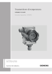
VENTILCONVETTORI A CASSETTA
WATER CASSETTE
IWC
DICHIARAZIONE DI CONFORMITÀ
DECLARATION OF CONFORMITY
La Galletti S.p.A. dichiara sotto la sua responsabilità, che i
ventilconvettori a cassetta IWC sono stati progettati, costruiti
e collaudati in conformità a quanto prescritto dalle Direttive
comunitarie: 2006/42/CE, 2004/108/CE, 2006/95/CE
Galletti S.p.A. hereby declares, under its sole responsibility, that
IWC water cassette series have been designed, built and tested in
conformity with the specifications of European Directives:
2006/42/CE, 2004/108/CE, 2006/95/CE
Bentivoglio, 27/09/2011
Galletti S.p.A.
Luca Galletti
Bentivoglio, 27/09/2011
Galletti S.p.A.
Luca Galletti
INFORMAZIONE PER IL CORRETTO SMALTIMENTO DEL
PRODOTTO AI SENSI DELLA DIRETTIVA EUROPEA
2002/96/CE
INFORMATION FOR CORRECT DISPOSAL OF THE PRODUCT
IN ACCORDANCE WITH THE EUROPEAN DIRECTIVE
2002/96/EC
Alla fine della sua vita utile questo apparecchio non deve essere
smaltito insieme ai rifiuti domestici. Deve essere consegnato presso
appositi centri di raccolta differenziata oppure presso i rivenditori che
forniscono questo servizio. Smaltire separatamente un apparecchio
elettrico ed elettronico consente di evitare possibili effetti negativi
sull’ambiente e sulla salute umana derivanti da uno smaltimento
inadeguato e permette di recuperare e riciclare i materiali di cui è
composto, con importanti risparmi di energia e risorse. Per sottolineare
l’obbligo di smaltire separatamente queste apparecchiature, sul
prodotto è riportato il simbolo del cassonetto barrato. Lo smaltimento
abusivo del prodotto da parte dell’utente comporta l’applicazione
delle sanzioni amministrative di cui al D.Lgs. n. 22/1997 (articolo 50
e successivi).
At the end of its working life this equipment must not be disposed of
as an household waste. It must be taken to special local community
waste collection centres or to a dealer providing this service.
Disposing of an electrical and electronic equipment separately avoids
possible negative effects on the environment and human health
deriving from an inappropriate disposal and enables its components to
be recovered and recycled to obtain significant savings in energy and
resources. In order to underline the duty to dispose of this equipment
separately, the product is marked with a crossed-out dustbin.
Codifica cassette IWC
1
2
3
4
5
6
7
8
9
I
W
C
0
3
2
F
0
1
n° Tubi
Comando
Motore
Revisione
Nome della serie
Taglia
IWC water cassette codes
1
2
3
4
5
6
7
8
9
I
W
C
0
3
2
F
0
1
n° Pipes
Controller
Motor
rev. Index
Range
2
Size
È severamente vietata la riproduzione anche parziale di questo manuale / All copying, even partial, of this manual is strictly forbidden
WC66000101 - Rev 04
IWC
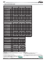
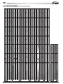
TABELLA PRESTAZIONI UNITÀ
Caratteristiche tecniche nominali ventilconvettori IWC modelli a 1 batteria
Modello
32
Velocità
42
52
1*
2
3
4
1*
2
3
4
1*
2
3
4
Resa raffreddamento totale (1)
kW
1,24
2,15
2,35
2,60
1,70
3,50
4,00
4,60
2,46
3,80
4,42
5,06
Resa raffreddamento sensibile (1)
kW
0,92
1,78
2,00
2,23
1,15
2,63
3,06
3,56
1,82
2,87
3,33
3,80
Portata acqua (1)
l/h
213
368
404
445
291
600
687
789
422
653
758
869
Perdita di carico (1)
kPa
3
8
9
11
3
11
14
17
7
14
18
23
Resa riscaldamento (2)
kW
1,55
2,83
3,11
3,49
1,87
4,35
4,85
5,70
3,35
5,33
6,14
6,75
Perdita di carico (2)
kPa
3
7
8,00
10
3
10
13
17
6
14
18
23
Resa riscaldamento (3)
kW
2,02
3,72
4,09
4,61
2,42
5,7
6,32
7,46
4,46
7,11
8,17
8,91
Portata acqua (3)
l/h
175
323
355
400
210
495
549
648
387
617
710
774
Perdita di carico (3)
kPa
2
6
7
8
2
7
9
12
5
12
16
18
Contenuto acqua
dm3
Portata aria
880
0,43
0,86
0,86
m3/h
180
400
460
520
200
530
630
750
370
630
760
Potenza assorbita
W
17
40
50
60
20
60
70
90
26
71
85
98
Potenza sonora (4)
dB/A
30
41
44
46
32
48
51
55
41
53
57
61
Pressione sonora (5)
dB/A
25
36
39
41
27
43
46
50
36
48
52
56
Attacchi idraulici
pollici
1 / 2
1 / 2
1 / 2
Dimensioni unità H x L x P
mm
273 x 575 x 575
273 x 575 x 575
273 x 575 x 575
Dimensioni pannello H x L x P
mm
64 x 730 x 730
64 x 730 x 730
64 x 730 x 730
Caratteristiche tecniche nominali ventilconvettori IWC modelli a 1 batteria
Modello
62
Velocità
82
102
1
2
3*
4
1
2
3
4*
1
2
3*
4
6,00
5,50
6,50
8,00
9,10
6,23
8,09
8,90
9,92
Resa raffreddamento totale (1)
kW
4,20
5,00
5,40
Resa raffreddamento sensibile (1)
kW
3,13
3,70
3,99
4,40
4,11
5,08
6,10
6,84
4,69
6,17
6,87
7,71
Portata acqua (1)
l/h
720
859
930
1.029
944
1.116
1.373
1.561
1.070
1.389
1.529
1.702
Perdita di carico (1)
kPa
16
22
25
30
21
28
41
51
27
42
50
60
Resa riscaldamento (2)
kW
5,40
6,40
7,10
7,70
6,28
8,52
9,42
10,19
7,34
9,53
10,59
11,69
Perdita di carico (2)
kPa
15
21
25
30
21
29
39
48
26
42
49
60
Resa riscaldamento (3)
kW
7,08
8,39
9,33
10,08
8,14
11,24
12,26
13,18
9,52
12,34
13,73
15,11
Portata acqua (3)
l/h
615
729
810
875
707
976
1.065
1.145
827
1.072
1.192
1.312
Perdita di carico (3)
kPa
12
16
19
22
12
21
24
27
16
26
31
37
Contenuto acqua
dm3
Portata aria
1,00
1,50
1,50
m3/h
850
1.060
1.160
1.300
830
190
1.270
1.400
1.200
1.700
1.980
2.300
Potenza assorbita
W
80
90
100
120
80
100
120
140
110
130
155
180
Potenza sonora (4)
dB/A
43
48
49
51
37
46
50
53
43
49
53
57
Pressione sonora (5)
dB/A
38
43
44
46
32
41
45
48
38
44
48
52
Attacchi idraulici
pollici
3 / 4
3 / 4
3 / 4
Dimensioni unità H x L x P
mm
273 x 776 x 776
290 x 1066 x 776
290 x 1066 x 776
Dimensioni pannello H x L x P
mm
64 x 860 x 860
64 x 1150 x 860
64 x 1150 x 860
Caratteristiche tecniche nominali ventilconvettori IWC modelli a 2 batterie
Modello
34
Velocità
44
1*
2
3
4
1*
2
3
4
Resa raffreddamento totale (1)
kW
1,03
1,72
1,88
2,05
1,52
2,88
3,28
3,76
Resa raffreddamento sensibile (1)
kW
0,81
1,51
1,66
1,82
1,07
2,27
2,60
3,00
Portata acqua (1)
l/h
177
295
323
351
295
494
563
645
Perdita di carico (1)
kPa
3
8
9
11
8
11
13
17
Resa riscaldamento (3)
kW
1,1
1,78
1,95
2,2
1,48
2,87
3,14
3,76
Portata acqua (3)
l/h
96
155
169
191
129
249
273
327
Perdita di carico (3)
kPa
11
25
29
36
7
22
26
36
Contenuto acqua
dm3
Portata aria
750
0,43
0,86
m3/h
180
400
460
520
200
530
630
Potenza assorbita
W
17
40
50
60
20
60
70
90
Potenza sonora (4)
dB/A
30
41
44
46
32
48
51
55
25
36
39
41
27
43
46
50
Pressione sonora (5)
dB/A
Attacchi idraulici batteria fredda
pollici
Attacchi idraulici batteria calda
1 / 2
1 / 2
pollici
1 / 2
1 / 2
Dimensioni unità H x L x P
mm
273 x 575 x 575
273 x 575 x 575
Dimensioni pannello H x L x P
mm
64 x 730 x 730
64 x 730 x 730
NOTE IWC 2 TUBI:
1 = temperatura acqua 7/12°C, temperatura aria B.S. 27°C, B.U. 19°C
2 = temperatura acqua ingresso 50°C, portata acqua come funzionamento in raffreddamento,
temperatura aria 20°C
3 = temperatura acqua 60/50°C, temperatura aria 20°C
4 = potenza sonora in conformità con ISO 3741 e ISO 3742
5 = pressione sonora calcolata per una distanza di 1 metro, fattore di direzionalità pari a 4
* Velocità aggiuntiva disponibile da Luglio 2012 Galletti SpA partecipa
al Programma di Certificazione EUROVENT. I prodotti interessati
compaiono nel sito www.eurovent-certification.com
WC66000101 - Rev 04
NOTE IWC 4 TUBI:
1 = temperatura acqua 7/12°C, temperatura aria B.S. 27°C, B.U. 19°C
3= temperatura acqua 70/60°C, temperatura aria 20°C
4= potenza sonora in conformità con ISO 3741 e ISO 3742
5 = pressione sonora calcolata per una distanza di 1 metro, fattore di direzionalità pari a 4
* Velocità aggiuntiva disponibile da Luglio 2012 Galletti SpA partecipa al Programma di
Certificazione EUROVENT. I prodotti interessati compaiono nel sito www.eurovent-certification.
com
È severamente vietata la riproduzione anche parziale di questo manuale / All copying, even partial, of this manual is strictly forbidden
3
IWC
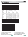
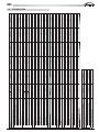
UNITS’ PERFORMANCE TABLE
Ratings and technical data of IWC fan coil units with 1 heat exchanger
Model
32
Speed
42
52
1*
2
3
4
1*
2
3
4
1*
2
3
4
Total cooling capacity (1)
kW
1,24
2,15
2,35
2,60
1,70
3,50
4,00
4,60
2,46
3,80
4,42
5,06
Sensible cooling capacity (1)
kW
0,92
1,78
2,00
2,23
1,15
2,63
3,06
3,56
1,82
2,87
3,33
3,80
Water flow (1)
l/h
213
368
404
445
291
600
687
789
422
653
758
869
Pressure drop (1)
kPa
3
8
9
11
3
11
14
17
7
14
18
23
Heating capacity (2)
kW
1,55
2,83
3,11
3,49
1,87
4,35
4,85
5,70
3,35
5,33
6,14
6,75
Pressure drop (2)
kPa
3
7
8,00
10
3
10
13
17
6
14
18
23
Heating capacity (3)
kW
2,02
3,72
4,09
4,61
2,42
5,7
6,32
7,46
4,46
7,11
8,17
8,91
Water flow (3)
l/h
175
323
355
400
210
495
549
648
387
617
710
774
Pressure drop (3)
kPa
2
6
7
8
2
7
9
12
5
12
16
18
Water content
dm3
Air flow
m3/h
180
400
460
520
200
530
630
750
370
630
760
880
W
17
40
50
60
20
60
70
90
26
71
85
98
dB/A
30
41
44
46
32
48
51
55
41
53
57
61
dB/A
25
36
39
41
27
43
46
50
36
48
52
56
Power input
Sound power level (4)
Sound pressure level (5)
Water connections
0,43
0,86
0,86
inches
1 / 2
1 / 2
1 / 2
Dimensions H x L x P
mm
273 x 575 x 575
273 x 575 x 575
273 x 575 x 575
Dimensions H x L x P
mm
64 x 730 x 730
64 x 730 x 730
64 x 730 x 730
Ratings and technical data of IWC fan coil units with 1 heat exchanger
Model
62
Speed
82
102
1
2
3*
4
1
2
3
4*
1
2
3*
4
6,00
5,50
6,50
8,00
9,10
6,23
8,09
8,90
9,92
Total cooling capacity (1)
kW
4,20
5,00
5,40
Sensible cooling capacity (1)
kW
3,13
3,70
3,99
4,40
4,11
5,08
6,10
6,84
4,69
6,17
6,87
7,71
Water flow (1)
l/h
720
859
930
1.029
944
1.116
1.373
1.561
1.070
1.389
1.529
1.702
Pressure drop (1)
kPa
16
22
25
30
21
28
41
51
27
42
50
60
Heating capacity (2)
kW
5,40
6,40
7,10
7,70
6,28
8,52
9,42
10,19
7,34
9,53
10,59
11,69
Pressure drop (2)
kPa
15
21
25
30
21
29
39
48
26
42
49
60
Heating capacity (3)
kW
7,08
8,39
9,33
10,08
8,14
11,24
12,26
13,18
9,52
12,34
13,73
15,11
Water flow (3)
l/h
615
729
810
875
707
976
1.065
1.145
827
1.072
1.192
1.312
Pressure drop (3)
kPa
12
16
19
22
12
21
24
27
16
26
31
37
Water content
dm3
Air flow
m3/h
850
1.060
1.160
1.300
830
190
1.270
1.400
1.200
1.700
1.980
2.300
W
80
90
100
120
80
100
120
140
110
130
155
180
Sound power level (4)
dB/A
43
48
49
51
37
46
50
53
43
49
53
57
Sound pressure level (5)
dB/A
38
43
44
46
32
41
45
48
38
44
48
52
Power input
Water connections
1,00
1,50
1,50
inches
3 / 4
3 / 4
3 / 4
Dimensions H x L x P
mm
273 x 776 x 776
290 x 1066 x 776
290 x 1066 x 776
Dimensions H x L x P
mm
64 x 860 x 860
64 x 1150 x 860
64 x 1150 x 860
Ratings and technical data of IWC fan coil units with 2 heat exchangers
Model
34
Speed
44
1*
2
3
4
1*
2
3
4
Total cooling capacity (1)
kW
1,03
1,72
1,88
2,05
1,52
2,88
3,28
3,76
Sensible cooling capacity (1)
kW
0,81
1,51
1,66
1,82
1,07
2,27
2,60
3,00
Water flow (1)
l/h
177
295
323
351
295
494
563
645
Pressure drop (1)
kPa
3
8
9
11
8
11
13
17
Heating capacity (3)
kW
1,1
1,78
1,95
2,2
1,48
2,87
3,14
3,76
Water flow (3)
l/h
96
155
169
191
129
249
273
327
Pressure drop (3)
kPa
11
25
29
36
7
22
26
36
Water content
dm3
Air flow
m3/h
180
400
460
520
200
530
630
750
W
17
40
50
60
20
60
70
90
dB/A
30
41
44
46
32
48
51
55
dB/A
25
36
39
41
27
43
46
50
Power input
Sound power level (4)
Sound pressure level (5)
Cooling heat exchanger water connections
inches
Heating heat exchanger water connections
0,43
0,86
1 / 2
1 / 2
inches
1 / 2
1 / 2
Dimensions H x L x P
mm
273 x 575 x 575
273 x 575 x 575
Dimensions H x L x P
mm
64 x 730 x 730
64 x 730 x 730
NOTES IWC WITH 2 PIPES:
1 = water temperature 7/12°C, air temperature dry bulb 27°C, wet bulb 19°C
2 = inlet water temperature 50°C, water flow rate same as in cooling mode, air inlet temperature 20°C
3 = water temperature 60/50°C, air temperature 20°C
4= sound power conforming to ISO 3741 and ISO 3742
5 = Sound pressure level measured at a distance of 1 m with a directivity factor of 4
* Additional speed available from July 2012
Galletti SpA takes part in the EUROVENT Certification Programme.
The products involved can be seen at www.eurovent-certification.com
4
NOTES IWC WITH 4 PIPES:
1 = water temperature 7/12°C, air temperature dry bulb 27°C, wet bulb 19°C
3 = Water temperature 70 - 60°C; air temperature 20°C
4 = sound power conforming to ISO 3741 and ISO 3742
5 = Sound pressure level measured at a distance of 1 m with a directivity factor of 4
* Additional speed available from July 2012
Galletti SpA takes part in the EUROVENT Certification Programme.
The products involved can be seen at www.eurovent-certification.com
È severamente vietata la riproduzione anche parziale di questo manuale / All copying, even partial, of this manual is strictly forbidden
WC66000101 - Rev 04
IWC
CONTENTS
INDICE
1.
2.
3.
4.
5.
6.
7.
8.
9.
10.
Generalità .................................................................................... 5
Presentazione .............................................................................. 6
Montaggio ................................................................................. 10
Collegamenti / Schemi elettrici ................................................... 12
Installazione del frontale / griglia ................................................ 24
Accessori .................................................................................. 25
Accensione ............................................................................... 32
Nome delle parti e telecomando ................................................. 34
Manutenzione ............................................................................ 44
Tabella caratteristiche ................................................................ 46
1 - GENERALITÀ
1.
2.
3.
4.
5.
6.
7.
8.
9.
10.
General........................................................................................ 5
Presentation ................................................................................ 6
Installation ................................................................................. 10
Connections / Electrical wiring diagrams .................................... 12
Facade / grille installation........................................................... 24
Accessories .............................................................................. 25
Starting ..................................................................................... 32
Name of parts and remote control unit ....................................... 34
Maintenance .............................................................................. 44
Features table ............................................................................ 46
1 - GENERAL
1.1 - PREMESSA
,O PDWHULDOH GHYH HVVHUH LQVWDOODWR PHVVR LQ VHUYL]LR H FRQVHUYDWR LQ
buono stato di funzionamento da personale qualificato e abilitato, nel
rispetto delle norme locali vigenti e con interventi eseguiti a regola d’arte.
1.1 - FOREWORD
The equipment must be installed, started-up and maintained by
authorised and qualified personnel, in accordance with local rules and
professional standards.
1.2 - CONDIZIONI GENERALI DI CONSEGNA
,QJHQHUDOHLOPDWHULDOHYLDJJLDDULVFKLRHSHULFRORGHOGHVWLQDWDULR
,OGHVWLQDWDULRGHYHLPPHGLDWDPHQWHHVSULPHUHGHOOHULVHUYHVFULWWHDOOR
spedizioniere qualora riscontri dei danni subiti dalla merce durante il
trasporto.
1RQDSSRJJLDUHRJJHWWLRDWWUH]]LVXOO·DSSDUHFFKLR
3RUUH O·DSSDUHFFKLR LO SL YLFLQR SRVVLELOH DO VXR SXQWR GL LQVWDOOD]LRQH
senza toglierlo dal suo imballaggio.
1.2 - GENERAL SUPPLY CONDITIONS
Generally speaking, the material is transported at the consignee’s risk.
The consignee must immediately provide the carrier with written
reserves if he finds any damage caused during transport.
Do not place objects or tools on the device.
Position the device as near as possible to its place of installation without
unpacking it.
1.3 - TENSIONE
Prima di effettuare qualsiasi operazione, verificare che la tensione e la
frequenza dell’apparecchio corrispondano esattamente a quelle della
rete.
1.3 - VOLTAGE
Before any operation, check that the voltage and the frequency indicated
on the device corresponds with that of the mains.
1.4 - LIMITI DI FUNZIONAMENTO
&LUFXLWRLGUDXOLFR
7HPSHUDWXUDPLQLPDG·HQWUDWDG·DFTXD&
7HPSHUDWXUDPDVVLPDG·HQWUDWDG·DFTXD
EDWWHULDSULQFLSDOH70°C
EDWWHULDVHFRQGDULD80°C
1.4 - OPERATION LIMITS
+\GUDXOLFFLUFXLW
PLQLPXPZDWHULQOHWWHPSHUDWXUH&
PD[LPXPZDWHULQOHWWHPSHUDWXUH
PDLQEDWWHU\70°C
VHFRQGDU\EDWWHU\80°C
Nota: Per ragioni di comfort (omogeneità della temperatura dell’aria nel
ORFDOHVLFRQVLJOLDGLQRQVXSHUDUH&G·HQWUDWDG·DFTXDQHOODEDWWHULD
3UHVVLRQHPDVVLPDGLVHUYL]LREDU
Note: For reasons relating to comfort (homogeneity of the air temperature
in the room), not exceeding a water inlet temperature of 55°C in the batter
LVUHFRPPHQGHG
0D[LPXPRSHUDWLQJSUHVVXUHEDUV
$ULDDPELHQWH
7HPSHUDWXUDPLQLPDGLULSUHVDDULD&
7HPSHUDWXUDPDVVLPDGLULSUHVDDULD&
$PELHQWDLU
0LQLPXPDLUUHFLUFXODWLRQWHPSHUDWXUH&
0D[LPXPDLUUHFLUFXODWLRQWHPSHUDWXUH&
Attenzione: Durante l’arresto per l’installazione, in caso di collegamento
ad una presa d’aria di rinnovo o nel caso di temperatura ambiente che
si avvicini a 0°C, si corre il rischio di gelare le tubazioni. Prevedere lo
scarico del circuito idraulico.
Warning: During installation shut-down, in case of connection to an
outside air vent or in case of ambient temperature near 0°C, there is a
risk that the hoses may freeze. Envisage draining the hydraulic circuit.
1.5 - USO
Questo apparecchio è destinato al condizionamento d’aria di locali per il
massimo benessere delle persone.
1.5 - USE OF EQUIPMENT
This equipment is intented for the air-conditioning of premises and to
provide comfort for the personnel.
1.6 - MODELLI
IWC 052F/T IWC 032F/T
IWC 062F/T IWC 034F
IWC 082F/T IWC 042F/T
IWC 102F/T IWC 044F
1.6 - MODELS
IWC 052F/T IWC 032F/T
IWC 062F/T IWC 034F
IWC 082F/T IWC 042F/T
IWC 102F/T IWC 044F
WC66000101 - Rev 04
È severamente vietata la riproduzione anche parziale di questo manuale / All copying, even partial, of this manual is strictly forbidden
5
IWC
2 - PRESENTAZIONE
2 - PRESENTATION
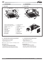
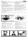
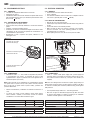
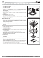
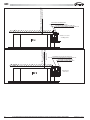
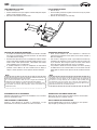
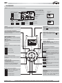
2.1 - DESCRIZIONE
10
2.1 - INSTALLATION
IWC 3-4-5
8
8
IWC 6-8-10
7
6
5
9
5
7
9
6
11
11
3
3
12
1
2
Entrata aria (griglia d’aspirazione)
Fermo di chiusura griglia di aspirazione
(su 2 lati)
3 Uscita aria (mandata su 4 lati)
4 Filtro aria
5 Staffe di sospensione
6 Entrata acqua
7 Uscita acqua
8 Spurgo aria batteria
9 Uscita condensa
10 Quadro elettrico
11 Spie e ricevitore
12 Telecomando
12
1
1
2
Air intake (intake grille)
Air intake latch
(on 2 sides)
3 Air outlet (blowing on 4 sides)
4 Air filter
5 Suspension brackets
6 Water intake
7 Water outlet
8 Air bleeder
9 Condensate outlet
10 Electrical box
11 Lamps and receiver
12 Remote control unit
2
1
2.2 - ACCESSORI FORNITI INSIEME ALL’APPARECCHIO
2.2 - ACCESSORIES SUPPLIED WITH THE UNIT
'LPDSHUSUDWLFDUHIRULSHUO·LQVWDOOD]LRQH
%DFLQHOODDXVLOLDULDUDFFROWDFRQGHQVD
0DQXDOHG·LQVWDOOD]LRQHHXVR
'ULOOLQJWHPSODWHIRUWKHLQVWDOODWLRQ
$X[LOLDU\FRQGHQVDWHWDQN
,QVWDOODWLRQDQGRSHUDWLQJLQVWUXFWLRQV
Nota: Il pannello / griglia è consegnato in un imballaggio separato.
Note: The facade / grille is delivered in a separate box.
SOLO PER IWC 6-8-10
URQGHOOHSHUODVRVSHQVLRQHGHOO·XQLWjDOVRIILWWR
IDVFHWWHSHUILVVDUHODWXED]LRQHGHOODFRQGHQVD
7XERIOHVVLELOHSHUUDFFRUGRFRQGHQVDPPLQWHUQR
0DVWLFHSHUODWHQXWDVWDJQDGHOSDVVDJJLRGHLFDYLHOHWWULFL
ONLY FOR ICW 6-8-10
ZDVKHUVWRGRDZD\ZLWKWKHFHLOLQJXQLW
WLHZUDSVWRVHFXUHWKHFRQGHQVDWHWXEH
+RVHIRUWKHFRQGHQVDWHFRQQHFWLRQLQWPP
6HDOLQJFRPSRXQGIRUWKHHOHFWULFDOFDEOHSDVVDJH
6
È severamente vietata la riproduzione anche parziale di questo manuale / All copying, even partial, of this manual is strictly forbidden
4
WC66000101 - Rev 04
IWC
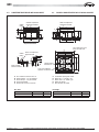
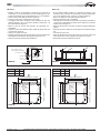
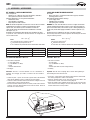
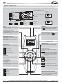
2.3 - CARATTERISTICHE FISICHE IWC 032-042-052F/T
Soffitto
Ceiling
2.3 -
PHYSICAL CHARACTERISTICS IWC 3-5 IWC 032-042-052F/T
Staffe di sospensione
Suspension brackets
Staffe di sospensione
Suspension brackets
575
575
70
506
544
D
B
600
296
273
41
23
192
152
135
228
A
259
259
41 min.
C
E
10
600
Staffe di sospensione
Suspension brackets
730
544
Tirante di sospensione
Suspension bolt
544
Quadro elettrico
Electrical box
506
Dadi e rondelle
Nuts and washers
730
10
10
41 min.
10
506
Soffitto
Ceiling
Lato ripresa aria nuova
Fresh air intake side
Lato raccordi idraulici
Hydraulic connections side
A
B
C
D
E
)RURFRQGHQVDHVWHUQRPP
(QWUDWDG·DFTXDµJDVIHPPLQD
8VFLWDG·DFTXDµJDVIHPPLQD
Spurgo aria batteria
3UHVDG·DULDGLULQQRYRPP
A
B
C
D
E
Peso netto
Net weight
Modello
Unità
Insieme pannello / griglia
WC66000101 - Rev 04
&RQGHQVDWHRSHQLQJ2'PP
:DWHULQOHWµIHPDOHJDV
:DWHURXWOHWµIHPDOHJDV
Battery air bleeder
1HZDLULQWDNHPP
IWC 3
18 kg
2,5 kg
IWC 4-5
20 kg
2,5 kg
Model
Unit
Frame / Grille Assembly
IWC 3
18 kg
2,5 kg
IWC 4-5
20 kg
2,5 kg
È severamente vietata la riproduzione anche parziale di questo manuale / All copying, even partial, of this manual is strictly forbidden
7
IWC
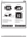
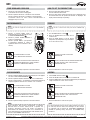
IWC 034-044F
Staffe di sospensione
Suspension brackets
Staffe di sospensione
Suspension brackets
575
E
C
575
70
544
F G
600
Staffe di sospensione
Suspension brackets
730
544
A
B
C
D
E
F
G
H
Quadro elettrico
Electrical box
Lato raccordi idraulici
Hydraulic connections side
)RURFRQGHQVDPPHVWHUQR
(QWUDWDG·DFTXDEDWWHULDSULQFLSDOHµJDVIHPPLQD
8VFLWDG·DFTXDEDWWHULDSULQFLSDOHµJDVIHPPLQD
(QWUDWDG·DFTXDEDWWHULDDGGL]LRQDOHµJDVIHPPLQD
8VFLWDG·DFTXDEDWWHULDDGGL]LRQDOHµJDVIHPPLQD
Sfiato aria batteria principale
Sfiato aria batteria addizionale
3UHVDG·DULDHVWHUQDPP
Peso netto
Modello
Unità
Insieme pannello / griglia
8
730
10
10
506
10
506
Dadi e rondelle
Nuts and washers
Lato ripresa aria nuova
Fresh air intake side
544
Tirante di sospensione
Suspension bolt
41 min.
Soffitto
Ceiling
296
41
23
B D
600
273
A
228
135
259
H
10
259
41 min.
506
192
152
Soffitto
Ceiling
A
B
C
D
E
F
G
H
&RQGHQVDWHRSHQLQJ2'PP
0DLQEDWWHU\ZDWHULQOHWµIHPDOHJDV
0DLQEDWWHU\ZDWHURXWOHWµIHPDOHJDV
$GGLWLRQDOEDWWHU\ZDWHULQOHWµIHPDOHJDV
$GGLWLRQDOEDWWHU\ZDWHURXWOHWµIHPDOHJDV
Main battery air bleeder
Additional battery air bleeder
1HZDLULQWDNHPP
Net weight
IWC 3
18 kg
2,5 kg
IWC 4-5
20 kg
2,5 kg
Model
Unit
Frame / Grille Assembly
IWC 3
18 kg
2,5 kg
È severamente vietata la riproduzione anche parziale di questo manuale / All copying, even partial, of this manual is strictly forbidden
IWC 4-5
20 kg
2,5 kg
WC66000101 - Rev 04
30 min. IWC6
IWC
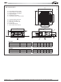
IWC 062-082-102F/T
860
A
B
C
D
E
F
)RURFRQGHQVDHVWHUQRPP
(QWUDWDG·DFTXDµJDVIHPPLQD
8VFLWDG·DFTXDµJDVIHPPLQD
Spurgo aria batteria
Passaggio dei cavi elettrici
3UHVDG·DULDGLULQQRYRPP[PP
Z
Y
A
B
C
D
E
F
&RQGHQVDWHRSHQLQJ2'PP
:DWHULQOHWµIHPDOHJDV
WDWHURXWOHWµIHPDOHJDV
Air vent valver
Electrical cable passage
1HZDLULQWDNHPP[PP
500
L
760
30 mini CWX 6
D C B
A
48
125
200
X
30
H
240
F
E
Peso netto
Modello
Unità
Insieme pannello / griglia
IWC 6
23 kg
5 kg
IWC 8-10
29 kg
7 kg
Modello
IWC 6
IWC 8-10
L
760
1050
H
310
340
X
260
290
Y
860
1150
Z
500
750
Net weight
Model
Unit
Facade / grille assembly
IWC 6
23 kg
5 kg
IWC 8-10
29 kg
7 kg
Model
IWC 6
IWC 8-10
L
760
1050
H
310
340
X
260
290
Y
860
1150
Z
500
750
WC66000101 - Rev 04
È severamente vietata la riproduzione anche parziale di questo manuale / All copying, even partial, of this manual is strictly forbidden
9
IWC
3 - INSTALLATION
3 - MONTAGGIO
3.1 - SCELTA DEL COLLOCAMENTO
3.1 - CHOOSING THE LOCATION
8QLWjDGDWWDSHUHVVHUHLQVWDOODWDLQORFDOLULSDUDWL,3
1RQ PRQWDUH O·XQLWj LQ XQ ORFDOH FRQWHQHQWH DWPRVIHUD LQILDPPDELOH
alcalina, acida, grassa, molto umida o esposta a proiezioni d’acqua. I
componenti sarebbero irrimediabilmente danneggiati.
6FHJOLHUHODSRVL]LRQHSLFHQWUDOHGHOORFDOH
9HULILFDUHFKHLOVRIILWWRVLDVXIILFLHQWHPHQWHVROLGRSHUVRVWHQHUHLOSHVR
dell’unità.
9HULILFDUH FKH QHO OXRJR VFHOWR QHVVXQ RJJHWWR RVWDFROHUj O·LPSLDQWR
e la sua manutenzione (travi, altezza del controsoffitto insufficiente,
pannelli del controsoffitto non smontabili, accesso per la manutenzione
impossibile...).
3UHYHGHUH XQ IDFLOH DFFHVVR SHU OD PDQXWHQ]LRQH LQ SDUWLFRODUH SHU OD
valvola motorizzata (e quadro elettrico per i modelli IWC 3-4-5).
3UHYHGHUH LO SDVVDJJLR GHL WXEL GHOO·DFTXD GHL FDYL HOHWWULFL H
dell’evacuazione della condensa.
/·DULDGHYHFLUFRODUHOLEHUDPHQWHDWWRUQRDOO·XQLWj
7KLVXQLWLVGHVLJQHGWREHLQVWDOOHGLQVKHOWHUHGURRPV,3
'R QRW LQVWDOO WKH GHYLFH LQ D URRP FRQWDLQLQJ LQIODPPDEOH DONDOLQH
acidic, greasy or very damp air, nor in one where water is liable to be
projected. The components will be irremediably damaged.
&KRRVHWKHPRVWFHQWUDOSRVLWLRQLQWKHURRP
&KHFNWKDWWKHFHLOLQJLVVXIILFLHQWO\VWXUG\WRVXSSRUWWKHXQLW·VZHLJKW
,Q WKH SRVLWLRQ FKRVHQ FKHFN WKDW QR REVWDFOH ZLOO LPSHGH LQVWDOODWLRQ
and maintenance (beam, insufficient false ceiling height, fixed false
ceiling panels, access impossible for maintenance, etc.).
3URYLGH DQ DFFHVV IRU HDV\ PDLQWHQDQFH QDPHO\ IRU WKH YDOYH DQG
electrical box for IWC 3-4-5 models).
3URYLGHIRUWKHZDWHUSLSHVHOHFWULFFDEOHVDQGWKHFRQGHQVDWHGLVFKDUJH
outlet.
$LUPXVWEHDEOHWRFLUFXODWHIUHHO\DURXQGWKHXQLW
Nota OD GLIIXVLRQH GHOO·DULD VDUj PHQR EXRQD VH O·DOWH]]D GHO ORFDOH q
superiore a metri 3.
Note: air diffusion will be less efficient if room height is greater than 3
meters.
1m
Bacinella ausiliaria
raccolta condensa
Auxiliary
condensate tank
1m
1m
1m
1m
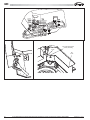
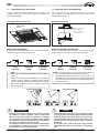
3.2 - MONTAGGIO IWC 3-4-5
3.2 - MONTAGGIO IWC 3-4-5
8WLOL]]DUHODGLPDGLIRUDWXUDIRUQLWDSHUGHWHUPLQDUHODSRVL]LRQHGHOOH
aste di sospensione (1).
/DGLPDGHYHHVVHUHFROORFDWDWUDGXHSURILOLD´7µGHOFRQWURVRIILWWR
&ROORFDUHLQVHGHOHDVWHGLVRVSHQVLRQHQRQIRUQLWH
0HWWHUH LO ODWR GHL UDFFRUGL QHOOD SRVL]LRQH SL DSSURSULDWD SHU L
collegamenti.
,OSURILORD´7µFKHVLWURYDVXOODWRGHOTXDGURHOHWWULFRGHYHHVVHUH
tolto momentaneamente.
&ROORFDUHLQVHGHO·XQLWjHYHULILFDUHFKHVLDDOLYHOOR
5HJRODUHODGLVWDQ]DWUDO·XQLWjHLOFRQWURVRIILWWRPPPDVVLPR
utilizzando i dadi delle aste.
9HULILFDUHODGLVWDQ]DDQFKHWUDODIODQJLDGLVRVSHQVLRQHHLOVRIILWWR
(7) (41 mm minimo). Una distanza inferiore può causare rumore se
l’unità tocca il soffitto.
8VHWKHGULOOLQJWHPSODWHSURYLGHGWRGHWHUPLQHWKHSRVLWLRQRIWKH
suspension rods (1).
7KHWHPSODWHPXVWEHSODFHGEHWZHHQ´7µUDLOVRIWKHIDOVHFHLOLQJ
,QVWDOOWKHVXVSHQVLRQURGVQRWVXSSOLHG
3ODFH WKH VLGH ZKHUH WKH FRQQHFWLRQV DUH ORFDWHG LQ WKH PRVW
appropriate position.
7KH ´7µ UDLO ORFDWHG RQ WKH HOHFWULFDO ER[ VLGH PXVW EH
temporarily removed.
3XWWKHXQLWLQSODFHDQGFKHFNWKDWLWLVOHYHO
$GMXVWWKHGLVWDQFHEHWZHHQWKHXQLWDQGWKHIDOVHFHLOLQJPD[
23 mm) by using the suspension rod nuts.
$OVRFKHFNWKHGLVWDQFHEHWZHHQWKHVXVSHQVLRQIODQJHDQGWKH
ceiling (7) (min. 41 mm). A lesser distance may create noise if the
unit touches the ceiling.
544
2
6
544 x 506
7
506
23 max.
23 max.
4
5
10
10
41 min.
10
41 min.
3
10
1
È severamente vietata la riproduzione anche parziale di questo manuale / All copying, even partial, of this manual is strictly forbidden
WC66000101 - Rev 04
IWC
IWC 6-8-10
IWC 6-8-10
8WLOL]]DUHODGLPDSHUGHWHUPLQDUHODSRVL]LRQHGHLIRULGHOOHDVWHGL
sospensione (1) e il foro da praticare nel contro-soffitto (figura 01). Per
le aste di sospensione usare un’asta filettata di mm. 8 o 10 di diametro.
9HGHUHOHPLVXUHVXOODWDEHOODTXLGLILDQFRILJXUD
&ROORFDUHLQVHGHOHDVWHGLVRVSHQVLRQHQRQIRUQLWH
/D OXQJKH]]D GHOOH DVWH GL VRVSHQVLRQH GHYH SHUPHWWHUH GL DYHUH XQD
distanza superiore a mm. 15 tra il basso dell’asta di sospensione e la
parte bassa dell’unità (figura 01).
0HWWHUH LO ODWR GHL UDFFRUGL QHOOD SRVL]LRQH SL DSSURSULDWD SHU L
collegamenti.
&ROORFDUHLQVHGHO·XQLWjXWLOL]]DQGRGDGLHURQGHOOHSHUILVVDUODVXOOHDVWH
di sospensione (figura 03).
9HULILFDUHFKHO·XQLWjVLDDOLYHOOR
5HJRODUHODGLVWDQ]DWUDO·XQLWjHODSDUWHVXSHULRUHGHOFRQWURVRIILWWRPP
48) utilizzando i dadi delle aste di sospensione (figure 01 e 03).
7RJOLHUHLOFDUWRQHGLSURWH]LRQHGHOODYHQWLOD]LRQH
8VH WKH GULOOLQJ WHPSODWH SURYLGHG WR GHWHUPLQH WKH SRVLWLRQ RI WKH
suspension rods (1) and the hole to be made in the false ceiling (figure
01). For the suspension rods, use dia. 8 or 10mm threaded rod.
5HIHUWRWKHGLPHQVLRQVLQWKHWDEOHRSSRVLWHILJXUH
,QVWDOOWKHVXVSHQVLRQURGVQRWVXSSOLHG
7KHOHQJWKRIWKHVXVSHQVLRQURGVPXVWEHORQJHQRXJKWRKDYHGLVWDQFH
of more than 15 mm between the bottom of the suspension rod and the
bottom of the unit (figure 01).
3ODFHWKHVLGHZKHUHWKHFRQQHFWLRQVDUHORFDWHGLQWKHPRVWDSSURSULDWH
position.
,QVWDOOWKHXQLWRQWKHVXVSHQVLRQURGVXVLQJWKHQXWVDQGZDVKHUVILJXUH
03).
&KHFNWKDWWKHXQLWLVOHYHO
$GMXVWWKHGLVWDQFHEHWZHHQWKHXQLWDQGWKHWRSRIWKHIDOVHFHLOLQJ
mm) using the nuts on the suspension rods (figures 01 and 03).
5HPRYHWKHSURWHFWLYHFDUGERDUGIURPWKHIDQ
Asta di sospensione
Suspension rod
Lock nut
Sotto
Botton
Flangia di sospensione
Suspension flange
48
FIGURA 03
48 mm
Controdado
Sopra
Top
2
FIGURA 01
A
B
Model
A
B
IWC 6
820
566
IWC 6
820
566
IWC 8-10
1110
856
IWC 8-10
1110
856
Modello
X
A (dimensione del foro nel soffitto)
820 (ceiling hole dimensions)
757 (centre-to-centre distance
between suspension rods)
757 (interasse delle
aste di sospensione)
A (ceiling hole dimensions)
B (centre-to-centre distance
between suspension rods)
Centre of
the grille
Hydraulic connections
Raccordi idraulici
820 (dimensione del foro nel soffitto)
X
Condensate drain tube
Centro
della griglia
Tubo d’evacuazione
della condensa
B (interasse delle aste di
sospensione)
1
2
15 mm mini
Nuts and washers (2 assemblies)
1
10
10
Dadi e rondelle (2 insiemi)
FIGURA 02
WC66000101 - Rev 04
È severamente vietata la riproduzione anche parziale di questo manuale / All copying, even partial, of this manual is strictly forbidden
11
IWC
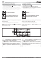
4 - COLLEGAMENTI - SCHEMI ELETTRICI
4 - CONNECTIONS - ELECTRIC WIRING DIAGRAMS
4.1 - COLLEGAMENTI IDRAULICI
4.1 - HYDRAULIC CONNECTION
&ROOHJDPHQWRµ02'(//,,:&µ02'(//,,:&
gas femmina sull’unità.
(QWUDWDG·DFTXDFROOHJDPHQWREDVVR
8VFLWDG·DFTXDFROOHJDPHQWRDOWR
3HU O·XWLOL]]R LQ UDIIUHGGDPHQWR q LQGLVSHQVDELOH LO PRQWDJJLR GL XQD
valvola motorizzata, altrimenti si corre il rischio di fuoriuscita dal
serbatoio condensa durante l’arresto dell’unità su interruzione del
termostato o in caso di guasto alla pompa della condensa (per il
PRQWDJJLRGHOODYDOYRODYHGHUHSDUDJUDIR´DFFHVVRULµ
µ ,:& 02'(/6 µ ,:& 02'(/6 IHPDOH JDV
connections on the unit.
:DWHULQOHWORZHUFRQQHFWLRQ
:DWHURXWOHWXSSHUFRQQHFWLRQ
)RUFROGZDWHUXVHDFRQWUROYDOYHPXVWEHLQVWDOOHGRWKHUZLVHWKHUHLV
a risk that the condensate tank may overflow if the unit shuts down due
to a thermostat disconnection or in case of condensate pump failure (for
YDOYHLQVWDOODWLRQUHIHUWRWKH´$FFHVVRULHVµSDUDJUDSK
Important: Securely hold the unit’s connections with a wrench while
tightening in order to avoid twisting the tubes inside the unit.
Attenzione: Bloccare correttamente i raccordi dell’unità con una
controchiave al momento del serraggio per evitare la torsione dei tubi
all’interno dell’unità.
&DUHIXOO\LQVXODWHWKHZDWHULQOHWDQGRXWOHWWXEHVDVZHOODVWKHHOHPHQWV
installed on the network (shut-off valves, ...). Use material that is adapted
to the installation conditions and water system.
7KH XQLW LV HTXLSSHG ZLWK DQ DLU EOHHGHU DERYH WKH FRQQHFWLRQV
Depending on the installations, other bleeders may be required on the
hydraulic network.
,VRODUHFRQFXUDLWXELG·HQWUDWDHG·XVFLWDGHOO·DFTXDQRQFKpLGLVSRVLWLYL
installati sulla rete (valvole d’arresto, …). Utilizzare un materiale
adeguato alle condizioni d’utilizzo ed alla temperatura dell’acqua.
/·XQLWj q GRWDWD GL XQR VSXUJR G·DULD VRSUD L UDFFRUGL 6HFRQGR JOL
impianti, può essere necessario, collocare altre valvole di spurgo sulla
rete idraulica.
IWC 3-4-5
max cm 12 (IWC 3-4-5)
max cm 30 (IWC 6-8-10)
LOSLFRUWRSRVVLELOH
as short as possible
IWC 6-8-10
3
1
2
3
4
4
min 2%
1
FIGURA 04
2
FIGURA 05
FIGURA 06
FIGURA 08
FIGURA 09
14
FIGURA 07
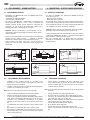
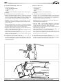
4.2 - COLLEGAMENTO DELLA CONDENSA
4.2 - CONDENSATE CONNECTION
6XOO·DWWDFFR VFDULFR FRQGHQVD GHOO·XQLWj UDFFRUGDUH LO WXER
flessibile (2) a corredo e fissarlo con la fascetta (3) fornita. Non
forzare sulla bocca d’evacuazione.
&ROOHJDUHXQWXERLQ39&ULJLGRDOO·HVWUHPLWjGHOWXERIOHVVLELOH
e fissarlo con una fascetta (3) a corredo.
Connect the hose (2) supplied to the unit’s drain fitting (1) and
secure it with the clamp (3) provided. Do not force the drain fitting.
Connect a rigid PVC pipe (4) on the end of the hose (2) and secure
it with the clamp (3) provided.
Nota: fissare le fascette mettendo le viti verso l’alto (figura 05).
Note: secure the clamps while ensuring that the screws are facing upward
(figure 05).
12
,VRODUHFRUUHWWDPHQWHODWXED]LRQHFRQVFKLXPDGLSROLHWLOHQH
$WWHQ]LRQHDOULVFKLRGLJHORG·LQYHUQRQHLFRQWURVRIILWWL
6HQHFHVVDULRqSRVVLELOHIDUULVDOLUHODFDQDOL]]D]LRQHGHOODFRQGHQVD
VXELWRGRSRO·XVFLWDGHOO·XQLWj$OWH]]DPDVVLPDFP(figura 06).
$FFHUWDUVL FKH OD FDQDOL]]D]LRQH G·HYDFXD]LRQH VLD LQ OHJJHUD
pendenza nel senso dello scarico e che non formi un sifone (figura
06).
/DFDQDOL]]D]LRQHGHYHHVVHUHVRVWHQXWDFRQDOFXQLVXSSRUWLILJXUD
07).
1RQLQVWDOODUHXQRVILDWRG·DULDILJXUDLQSRVL]LRQHHUUDWD
1RQLQVWDOODUHODFDQDOL]]D]LRQHFRQXQDSHQGHQ]DYHUVRO·DOWRYLFLQR
all’uscita (figura 09). Si corre il rischio di un ritorno d’acqua quando
l’unità si arresta (figure 09).
Carefully insulate the hose with polyethylene foam.
Be aware of the risk of freezing in false ceilings during the winter.
If necessary, the condensate tube can be raised immediately after the
XQLW·VRXWOHW0D[KHLJKWFPILJXUH
Make sure that the drain line has a slight slope in the flow direction
and that it does not form a siphon (figure 06).
The tube must be held with supports (figure 07).
Do not install air intakes (figure 08).
The line must not have an upward slope near the outlet.
There is a risk that water may flow back when the unit is off. (figure
09).
È severamente vietata la riproduzione anche parziale di questo manuale / All copying, even partial, of this manual is strictly forbidden
WC66000101 - Rev 04
IWC
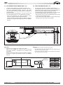
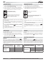
4.3 - COLLEGAMENTO ARIA DI RINNOVO (IWC 3-4-5)
4.3 - FRESH AIR CONNECTION IWC 3-4-5
/·XQLWjSXzHVVHUHFROOHJDWDDGXQFRQGRWWRG·DULDHVWHUQD
,O PRWRUH GHO YHQWLODWRUH VXSSOHPHQWDUH SHU OD SUHVD G·DULD HVWHUQD
deve avere un’alimentazione elettrica separata e poter essere
comandato tramite un interruttore bipolare On/Off con dispositivo di
protezione elettrico.
3HUHYLWDUHSUREOHPLGLIXQ]LRQDPHQWRHGLUXPRUHODSRUWDWDG·DULD
nuova deve rappresentare circa il 10% della portata d’aria totale.
$SULUH LO IRUR SUHGLVSRVWR ILVVDUH XQD IODQJLD PP
sull’unità e collegare il condotto isolato termicamente.
- Installare all’esterno una griglia con filtro per impedire l’aspirazione
di polvere e di impurità che potrebbero sporcare lo scambiatore
dell’unità.
135
90b0'
The unit can be connected to an outside air inlet conduit (17).
The additional fan motor for the outside air intake is equipped with a
separate electric power supply and can be controlled by means of a
two-pole On/off switch with an electrical protection device.
To avoid operating and noise-related problems, the new air output
should represent approximately 10% of the total air output.
- 2SHQWKHNQRFNRXWVHFXUHDPPIODQJHRQWKHXQLWDQG
connect the thermal insulated conduit.
- On the exterior, install a grille with filter to prevent drawing in dust
and debris which could clog the unit’s exchanger.
0
ø9
18
135
ø 70
.9
ø2
17
IWC 6-8-10
L’unità può essere collegata ad un condotto d’aria esterna.
- Aprire il foro pre-tagliato (A), fissare una bocca di raccordo
(non fornito) sull’unità e raccordarlo ad una conduttura isolata
termicamente.
- Installare all’esterno una griglia con filtro per impedire l’aspirazione
di polvere e di impurità che potrebbero sporcare lo scambiatore
dell’unità.
IWC 6-8-10
The unit can be connected to an outside air inlet conduit.
- Open the knock-out (A), secure a connection sleeve (not supplied) to the unit
and connect a thermal insulated conduit.
- On the exterior, install a grille with filter to prevent drawing in dust and debris
which could clog the unit’s exchanger.
A
60
IRUL
KROHV
ø1
X
12
55
WC66000101 - Rev 04
Modello
IWC 6
IWC 8-10
X
220
250
Model
IWC 6
IWC 8-10
X
220
250
È severamente vietata la riproduzione anche parziale di questo manuale / All copying, even partial, of this manual is strictly forbidden
13
IWC
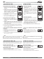
4.4 - COLLEGAMENTO ELETTRICO
4.4 - ELECTRICAL CONNECTION
4.4.1 - GENERALITÀ
I condotti dei collegamenti elettrici devono essere fissi.
Apparecchio di classe 1.
L’installazione elettrica deve essere realizzata nel rispetto delle norme e
delle regolamentazioni in vigore (con attenzione particolare alle norme
CEI 364).
NF C 15-100
4.4.1 - GENERALS
The electrical connection conduits must be fixed.
Class 1 appliance.
The electrical installation must be carried out in compliance with the
CEI 364).
rules in force (especially NF C 15-100
4.4.2 - PARTICOLARI DEL COLLEGAMENTO
Togliere il coperchio del quadro elettrico.
Alcuni serracavi sono previsti per mantenere i cavi alla loro entrata nel
quadro.
Collegare i cavi sulle morsettiere previste.
Assicurarsi che i fili siano correttamente collegati sui morsetti. Il cattivo
collegamento dei fili può provocare problemi di funzionamento e il
surriscaldamento e quindi incendi.
Ricollocando in sede il coperchio del quadro, attenzione a non
danneggiare i cavi.
IWC 6-8-10
4.4.2 - DETAIL OF THE CONNECTION
Remove the cover of the electrical box.
Cable clamps are provided to maintain the cable at their entry point into
the box.
Connect the cables to the terminals provided.
Make sure that the wires are correctly connected to the terminals.
Incorrect connection can cause operating problems as well as
overheating which can cause fires.
When replacing the box’s cover, be sure not to pinch the cables.
IWC 3-4-5
Passaggio dei cavi elettrici
Electrical cable passage
Entrata dei cavi elettrici nel quadro
Cable inlet into the unit
Coperchio del quadro elettrico
Electrical box cover
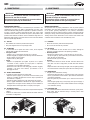
4.4.3 - ALIMENTAZIONE
$OLPHQWD]LRQH97HUUD+]FRQGLVSRVLWLYRGLSURWH]LRQH
e di sezionamento (non fornito), in conformità alle norme e delle
regolamentazioni in vigore. La protezione deve essere garantita da un
interruttore bipolare (non fornito).
4.4.3 - POWER SUPPLY
230V / 1 + Earth / 50Hz power supply from a power supply and
protection device (not included) in accordance with the rules in force.
The protection must be ensured by a two-pole circuit breaker (not
supplied).
Nota: L’unità è prevista per un collegamento su un’alimentazione generale
con regime neutro TT (neutro a terra) o TN.S (messa in neutro) secondo
NF C 15-100. Per un regime neutro IT (neutro isolato), prevedere una
protezione differenziale.
Note: The unit is designed to be connected to a power supply having a TT
neutral regime (neutral to ground) or TN.S regime (to neutral) as per NF C
15-100. For a IT neutral point connection (isolated neutral), provide ground
fault protection.
'
XUDQWHLOIXQ]LRQDPHQWRqWROOHUDELOHXQDYDULD]LRQHGLWHQVLRQHGL
10 %.
/H VH]LRQL VRQR IRUQLWH D WLWROR LQGLFDWLYR 4XHVWH XOWLPH GHYRQR
essere verificate e adattate, se necessario, secondo le condizioni
d’installazione e in funzione della normativa in vigore.
The acceptable voltage variation is ± 10% during operation.
Wire sizes are given for informational purposes only. Wire sizes must
be checked and adapted, as required, according to the installation
conditions and with regard to current standards.
Modello
Intensità massima assorbita (A)
Sezione (mm2)
IWC 3
0,25
1,5
IWC 4-5
0,40
1,5
Modello
Max. current consumption (A)
Section (mm2)
IWC 3
0,25
1,5
IWC 4-5
0,40
1,5
Modello
Intensità massima assorbita (A)
Sezione (mm2)
IWC 6-8
0,65
1,5
IWC 10
0,95
1,5
Modello
Max. current consumption (A)
Section (mm2)
IWC 6-8
0,65
1,5
IWC 10
0,95
1,5
14
È severamente vietata la riproduzione anche parziale di questo manuale / All copying, even partial, of this manual is strictly forbidden
WC66000101 - Rev 04
IWC
Il collegamento dell’alimentazione si realizza sul morsetto X1 (morsetti U,
N e PE) della scheda circuito stampato posta nel quadro elettrico (vedere
disegno qui accanto).
WIRED MODELS
The power supply is connected to terminal strip X1 (terminals U,
N, and PE) of the printed circuit board located in the electric box
(see drawing opposite).
QUADRO ELETTRICO
ELECTRICAL BOX
Scheda circuito stampato
Printed circuit board
Morsetto riscaldamento elettrico
Electrical heating terminal
PE
N
U
U N PE
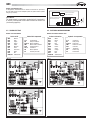
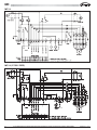
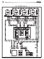
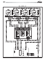
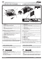
4.5 - SCHEMI ELETTRICI
4.5 - ELECTRICAL WIRING DIAGRAMS
MODELLI CON TELECOMANDO
MODELS WITH REMOTE CONTROL UNIT
Colori dei fili
WHT
BLK
GRY
RED
YEL
BRN
VLT
ORG
PNK
BLU
GRN/YEL
Bianco
Nero
Grigio
Rosso
Giallo
Marrone
Viola
Arancione
Rosa
Blu
Giallo/Verde
IWC 3-4
Simboli dei componenti
C1,2
DP
FLAP1,2
FMI
PCB
TH1,2
PR
FS
Condensatore
Pompa condensa
Motore deflettore
Motore interno ventola
Scheda elettrica
Termistore
Relè di potenza
Sensore per livello
N
F
Colours of the wires
WHT
BLK
GRY
RED
YEL
BRN
VLT
ORG
PNK
BLU
GRN/YEL
White
Black
Grey
Red
Yellow
Brown
Violet
Orange
Pink
Blue
Yellow/Green
230V/1/50Hz
MODELLI CON COMANDO A FILO
Symbols of components
C1,2
DP
FLAP1,2
FMI
PCB
TH1,2
PR
FS
Condenser
Drain pump
Flap motor
Indoor fan motor
Controller
Thermistor
Power relay
Float switch
IWC 5
IWC 6-8-10
WC66000101 - Rev 04
È severamente vietata la riproduzione anche parziale di questo manuale / All copying, even partial, of this manual is strictly forbidden
15
IWC
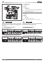
1 - Impostazione JUMPERS
C = Chiuso
O = Aperto
2 - Funzioni:
A = Disponibile
E = Non disponibile
(Quando selezionata dal telecomando, tutte le spie lampeggiano)
Nota:
Le configurazioni diverse da quella di fabbrica devono essere
eseguite da personale qualificato.
1 - Setting JUMPERS
C = Close
O = Open
2 - Function:
A = Available
E = Not available
(When selected, all leds blinking)
Note:
The different factory setting must be made to special worker.
AVVERTIMENTO
WARNING
Assicurarsi che l’unità terminale sia spenta e che l’interruttore
principale di corrente sia commutato su OFF (Spento) prima di
aprile l’unità.
To avoid electric shock, be sure to turn the air conditioner off and
disconnect the power before opening the unit.
4.5.1 - CONFIGURAZIONE SISTEMA DI FABBRICA:
FREDDO O CALDO CON VALVOLA
4.5.1 - FACTORY SYSTEM CONFIGURATION:
COOLING OR HEATING WITH VALVE
SISTEMA FREDDO O
CALDO
FUNZIONI
JUMPERS
4.5.2 - CONFIGURAZIONE SISTEMA: UNITA’ 4 TUBI CON VALVOLA
SISTEMA FREDDO O
CALDO
16
FUNZIONI
JUMPERS
COOLING OR
HEATING SYSTEM
FUNCTIONS
JUMPERS
4.5.2 - SYSTEM CONFIGURATION: 4 TUBES UNIT WITH VALVE
COOLING OR
HEATING SYSTEM
FUNCTIONS
È severamente vietata la riproduzione anche parziale di questo manuale / All copying, even partial, of this manual is strictly forbidden
JUMPERS
WC66000101 - Rev 04
IWC
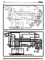
4.5.3 - TELECOMANDO: SELETTORI DI INDIRIZZO
4.5.3 - REMOTE CONTROL: ADDRESS SWITCHES
AVVERTIMENTO
WARNING
Assicurarsi che l’unità terminale sia spenta e che l’interruttore
principale di corrente sia commutato su OFF (spento) prima di
aprire l’unità.
Se vengono installate più unità (fino a 4) nello stesso locale,
è necessario indirizzare ogni telecomando alla propria unità
interna.
unità
unit
telecomando
remote control
unità interna
To avoid electric shock, be sure to turn the air conditioner off and
disconnect the power before opening the unit.
If you are installing more than 1 indor unit (up to 4) in the same
room, it is necessary for you to assign each unit its own address
so each can be operated by its own remote control unit.
indoor unit
Telecomando
Remote control
SCHEDA ELETTRONICA
PCB
MODELLI CON COMANDO A FILO
Simboli dei componenti
B1
C1,2
F1
K1
K2
M1
M2
PCB
PR
Sensore per livello
Condensatore ventilatore
Fusibile
Relè d’allarme
Relè d’allarme
Motoventilatore
Pompa condensa
Scheda circuito stampato
Relè di potenza
WC66000101 - Rev 04
WIRED MODELS
Simbols of components
Colori dei Fili
WHT
BLK
GRY
RED
YEL
BRN
VLT
ORG
PNK
BLU
GRN/YEL
Bianco
Nero
Grigio
Rosso
Giallo
Marrone
Viola
Arancione
Rosa
Blu
Giallo/Verde
B1
C1,2
F1
K1
K2
M1
M2
PCB
PR
Float switch
Fan condenser
Fuse
Alarm relay
Alarm relay
Fan motor
Drain pump
Printed circuit board
Power relay
Colours of the wires
WHT
BLK
GRY
RED
YEL
BRN
VLT
ORG
PNK
BLU
GRN/YEL
È severamente vietata la riproduzione anche parziale di questo manuale / All copying, even partial, of this manual is strictly forbidden
White
Black
Grey
Red
Yellow
Brown
Violet
Orange
Pink
Blue
Yellow/Green
17
IWC
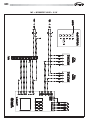
IWC 3-4
Valve
IWC 3-4 (2 TUBI-2 PIPES)
/ HEATING
VALVE
7
18
È severamente vietata la riproduzione anche parziale di questo manuale / All copying, even partial, of this manual is strictly forbidden
WC66000101 - Rev 04
IWC
IWC 5
IWC 6-8-10
WC66000101 - Rev 04
È severamente vietata la riproduzione anche parziale di questo manuale / All copying, even partial, of this manual is strictly forbidden
19
IWC
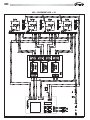
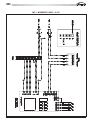
IWC + MYCOMFORT BASE + KP
20
È severamente vietata la riproduzione anche parziale di questo manuale / All copying, even partial, of this manual is strictly forbidden
WC66000101 - Rev 04
IWC
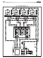
IWC + MYCOMFORT MEDIUM + KP
WC66000101 - Rev 04
È severamente vietata la riproduzione anche parziale di questo manuale / All copying, even partial, of this manual is strictly forbidden
21
IWC
IWC + MYCOMFORT LARGE + KP
22
È severamente vietata la riproduzione anche parziale di questo manuale / All copying, even partial, of this manual is strictly forbidden
WC66000101 - Rev 04
IWC
IWC + LED503 + KP
WC66000101 - Rev 04
È severamente vietata la riproduzione anche parziale di questo manuale / All copying, even partial, of this manual is strictly forbidden
23
IWC
IWC + MYCOMFORT LARGE + 0-10V
24
È severamente vietata la riproduzione anche parziale di questo manuale / All copying, even partial, of this manual is strictly forbidden
WC66000101 - Rev 04
IWC
IWC + MYCOMFORT LARGE + 0-10V
WC66000101 - Rev 04
È severamente vietata la riproduzione anche parziale di questo manuale / All copying, even partial, of this manual is strictly forbidden
25
IWC
5 - INSTALLAZIONE DEL FRONTALE-GRIGLIA / FRAME-GRILLE INSTALLATION
Il frontale / griglia è consegnato in un cartone a parte
- Codice K60N129T per IWC3-4-5
- Codice K60N130T per IWC6
- Codice K60N131T per IWC8-10
3ULPDG·LQVWDOODUHLOIURQWDOH
- Togliere le viti (1) di bloccaggio dei fermi (2) su ogni lato (ricordarsi di rimettere queste viti
dopo l’installazione).
- Per aprire la griglia (3), spostare i due fermi (2) nel senso della freccia.
- Aprire la griglia (3) di 45°.
- Staccare la funicella di sicurezza (4) del quadro (ricordarsi di agganciarla di nuovo dopo
l’installazione).
- Sollevare la griglia per toglierla dal quadro.
3HULQVWDOODUHLOIURQWDOH
- Girate i due clip di bloccaggio (5) verso il basso.
- Agganciare il quadro del pannello (6) all’unità per mezzo dei due ganci (7) facendoli
corrispondere ai clip di bloccaggio (5).
Nota (per modelli IWC 6-8-10):
- Attenzione ad orientare il quadro del pannello, i ganci hanno una larghezza diversa. Presentarli
esattamente di fronte al clip di bloccaggio corrispondente.
- Verificare l’esatta posizione del quadro del pannello rispetto al controsoffitto. Se necessario
regolare la posizione dell’unità interna.
- Fissare il quadro del pannello all’unità utilizzando le viti speciali e le rondelle (8) fornite.
- Collocare in sede la griglia (3) verificando che il filtro (9) sia correttamente posizionato.
- Agganciare la funicella di sicurezza al quadro, chiudere la griglia e rimettere le viti di bloccaggio
dei fermi (2).
The frame / grille comes in a separate box.
- Code K60N129T for IWC3-4-5
- Code K60N130T for IWC6
- Code K60N131T for IWC8-10
%HIRUHLQVWDOOLQJWKHIDFDGH
- Remove the retaining screws (1) from the locks (2) on each side (remember to replace these
screws after installation).
- To open the grille (3), turn the two locks (2) in the direction of the arrow.
- Open the grille (3) 45°.
- Detach the safety cord (4) from the frame (remember to replace it again after installation).
- Pull the grille inward to remove it from the frame.
7RLQVWDOOWKHIDFDGH
- Turn the two locking clips (5) downward.
- Attach the frame of the facade (6) to the unit with the two hooks (7) by lining them up with the
locking clips (5).
4
1
2
5
5
6
7
8
Note (for IWC 6-8-10 models):
- Observe the position of the facade frame as the hooks are not the same size. Correctly present
them in front of the corresponding locking clips.
- Check the correct position of the facade frame in relation to the false ceiling. Adjust the position
of the internal unit, as required.
- Secure the facade frame to the unit using the special screws and washers (8) provided.
- Fit the grille (3) making sure that the filter (9) is correctly installed.
- Hook the grille safety cord to the frame, close the grille and replace the lock retaining screws.
26
3
È severamente vietata la riproduzione anche parziale di questo manuale / All copying, even partial, of this manual is strictly forbidden
9
3
WC66000101 - Rev 04
IWC
6 - ACCESSORI / ACCESSORIES
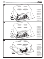
KIT VALVOLA A 3 VIE E 4X2 MOTORIZZATA
,ONLWVLFRPSRQHGL
- Valvola a 3 vie / 4 attacchi con by pass incorporato, realizzata in
RWWRQHSUHVVLRQHPDVVLPDGLHVHUFL]LREDU
$WWXDWRUHHOHWWURWHUPLFRFRQOHVHJXHQWLFDUDWWHULVWLFKH
- alimentazione 230 V
- azione ON/OFF (o modulante)
- tempo di apertura totale 4 minuti
NOTA: La Valvola 4X2 permette di convertire in unità a 4 tubi una cassetta
originariamente con batteria a 2 tubi. Il kit comprende due valvole
VSHFLDOL´[µGXHDWWXDWRULRQRIIRPRGXODQWLDVHFRQGDGHO
codice del kit valvole) ed il relativo kit tubi. L’installazione è mostrata
nelle figure 1,2,3, e 4.
Kit idraulico per l’installazione della valvola sullo scambiatore di calore.
Le perdite di carico dell’assieme valvola/kit idraulico di collegamento si
ULFDYDQRGDOODIRUPXOD
3-WAY AND 4X2 MOTOR DRIVEN VALVE KIT
NLWLQFOXGHV
- Brass 3-way valve / 4 connections with built-in by-pass, maximum
operating pressure 16 bar;
(OHFWURWKHUPDO212))DFWXDWRUIHDWXULQJ
SRZHUVXSSO\9
- ON/OFF function (or floating)
WRWDORSHQLQJWLPHPLQXWHV
REMARK: 7KH´[µYDOYHNLWDOORZVWRFRQYHUWLQDSLSHXQLWWKHZDWHU
cassette originally equipped with a 2 pipe coil. The valve kit includes two
VSHFLDO´[µZDWHUYDOYHVWZRDFWXDWRUVRQRIIRUIORDWLQJGHSHQGLQJRQ
the kit code) and the water piping. Installation is shown in pictures 1,2,3,
and 4.
Hydraulic kit for the installation of the valve on the heat exchanger.
Pressure drops of the valve/connection hydraulic kit assembly are calculated
XVLQJWKHIROORZLQJIRUPXOD
2
2
'PW = (QW / K )
V
Dove:
2
'PW è la perdita di carico espressa in kg/cm
3
QW è la portata acqua espressa in m /h
KV è il coefficiente di portata della valvola individuabile dalla tabella
'PW = (QW / K )
V
Where:
2
'PW pressure drop in kg/cm
3
QW water flow rate in m /h
KV water flow rate coefficient obtained from the following table
Valvola
Kvs via diritta
Kv by-pass
Valve
Kvs straight
Kv by-pass
´
1,7
1,2
´
1,7
1,2
´
2,8
1,8
´
2,8
1,8
´[
2,2
2,2
´[
2,2
2,2
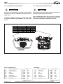
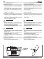
KIT VALVOLA MOTORIZZATA - IWC 3-4-5
VALVE KIT - IWC 3-4-5
,ONLWYDOYRODFRPSUHQGH
- il corpo della valvola,
R1,33/(6µ00
- kit tubi,
- l’attuatore elettrotermico.
0RQWDJJLR
7KHYDOYHNLWLQFOXGHV
- the valve body,
RU1,33/(6µ00
- piping,
DFWXDWRUZLWK9´2Q2IIµKHDWLQJHOHPHQW
$VVHPEO\
Attenzione: bloccare i raccordi dell’unità con una controchiave al
momento del serraggio per evitare la tensione dei tubi all’interno
dell’unità.
Important: Hold the unit’s couplings with a wrench while tightening to
avoid twisting the tubes inside the unit.
$YYLWDUHODSDUWH´SH]]RµGHLUDFFRUGLDJLXQWRVIHULFRVXOOHILOHWWDWXUH
della valvola. Utilizzare la pasta o il teflon per la tenuta stagna.
&ROORFDUHLQVHGHO·D]LRQDWRUHWHUPLFRVXOODYDOYRODHFROOHJDUHLOFDYRQHO
quadro elettrico come da schema elettrico.
)LVVDUHODEDFLQHOODDXVLOLDULDIRUQLWDFRQO·XQLWjVXOODWRVRWWRODYDOYROD
Collocare il raccordo della bacinella nel foro sotto la valvola. Fissare la
bacinella con le due viti fornite.
6FUHZWKH´SDUWµSRUWLRQRIWKHVZLYHOFRXSOLQJRQWRWKHYDOYHWKUHDGV
Use sealing compound or Teflon on the threads.
,QVWDOO WKH WKHUPDO DFWXDWRU RQ WKH YDOYH DQG FRQQHFW WKH FDEOH LQ WKH
electrical box as shown in the electric wiring diagram.
0RXQWWKHDX[LOLDU\WDQNVXSSOLHGZLWKWKHXQLWRQWKHVLGHEHORZWKH
valve. House the tank’s fitting in the hole underneath the valve. Secure
the tank with the two screws provided.
Out acqua
Water out
In acqua
Water in
WC66000101 - Rev 04
È severamente vietata la riproduzione anche parziale di questo manuale / All copying, even partial, of this manual is strictly forbidden
27
IWC
Out acqua
Water out
In acqua
Water in
Out acqua addizionale
Additional water out
In acqua addizionale
Additional water in
Vite
Screw
Raccordo della bacinella
Auxiliary tank fitting
Vite
Screw
28
È severamente vietata la riproduzione anche parziale di questo manuale / All copying, even partial, of this manual is strictly forbidden
WC66000101 - Rev 04
IWC
KIT VALVOLA MOTORIZZATA - IWC 6-8-10
VALVE KIT - IWC 6-8-10
,ONLWYDOYRODFRPSUHQGH
- il corpo della valvola motorizzata,
1,33/(6µ00
- kit tubi,
O·DWWXDWRUHWHUPLFRDGHOHPHQWRULVFDOGDQWH´7XWWRRQLHQWHµ9
0RQWDJJLR
A - Valvola direttamente sui raccordi idraulici dell’unità
0RQWDUHLPDQLFRWWLULGX]LRQHµPDVFKLRµIHPPLQDVXLUDFFRUGL
IHPPLQDGHOO·XQLWjSRLDYYLWDUHODSDUWH´SH]]LµGHLUDFFRUGLDJLXQWR
sferico sui manicotti di riduzione. Utilizzare una chiave regolabile o una
chiave esagonale. Utilizzare la pasta o il teflon per la tenuta stagna.
7KHYDOYHNLWLQFOXGHV
- the valve body,
1,33/(6µ00
- piping,
DFWXDWRUZLWK9´2Q2IIµKHDWLQJHOHPHQW
$VVHPEO\
A - Valve directly on the unit’s hydraulic connections
)LWWKHµPDOHµIHPDOHDGDSWHUFRXSOLQJVRQWKHXQLW·VIHPDOH
FRQQHFWRUVWKHQVFUHZWKH´SDUWµSRUWLRQRIWKHVZLYHOFRXSOLQJVRQWR
the adapter couplings. Use a stepped spanner or a hex wrench. Put
sealing compound or Teflon tape on the threads.
Attenzione: bloccare correttamente i raccordi dell’unità con una
controchiave al momento del serraggio per evitare la torsione dei tubi
all’interno dell’unità.
Important: Hold the unit’s couplings with a wrench while tightening to
avoid twisting the tubes inside the unit.
0RQWDUHLPDQLFRWWLULGX]LRQHµIHPPLQDµPDVFKLRVXOODYDOYROD
SRLDYYLWDUHODSDUWH´SH]]RµGHLUDFFRUGLDJLXQWRVIHULFRVXLPDQLFRWWL
di riduzione. Utilizzare la pasta o il teflon per la tenuta stagna.
0RQWDUH OD YDOYROD VXOO·XQLWj D OLYHOOR GHL UDFFRUGL D JLXQWR VIHULFR /D
valvola si monta all’uscita d’acqua dell’unità.
&ROORFDUHLQVHGHO·DWWXDWRUHWHUPLFRVXOODYDOYRODHFROOHJDUHLOFDYRQHO
quadro elettrico come da schema elettrico.
)LVVDUHODEDFLQHOODDXVLOLDULDIRUQLWDFRQO·XQLWjVXOODWRVRWWRODYDOYROD
Collocare il raccordo della bacinella nel foro sotto la valvola. Fissare la
bacinella con le due viti fornite
B - Valvola lontano dai raccordi idraulici dell’unità
/D YDOYROD SXz HVVHUH PRQWDWD VX XQD WXED]LRQH QRQ IRUQLWD FKH
consenta di allontanarla dai raccordi idraulici dell’unità. In questo caso
collocare la valvola lungo l’unità, sul lato, in modo da trovarsi al di sopra
della bacinella ausiliaria.
)LW WKH µ IHPDOH µ PDOH DGDSWHU FRXSOLQJV RQ WKH YDOYH WKHQ
VFUHZ WKH ´ SDUWµ SRUWLRQ RI WKH VZLYHO FRXSOLQJV RQWR WKH DGDSWHU
couplings. Use sealing compound or Teflon on the threads.
)LWWKHYDOYHRQWKHXQLWDWWKHOHYHORIWKHVZLYHOFRXSOLQJV7KHYDOYHLV
installed at the unit’s water outlet.
,QVWDOO WKH WKHUPDO DFWXDWRU RQ WKH YDOYH DQG FRQQHFW WKH FDEOH LQ WKH
electrical box as shown in the electric wiring diagram.
0RXQWWKHDX[LOLDU\WDQNVXSSOLHGZLWKWKHXQLWRQWKHVLGHEHORZWKH
valve. House the tank’s fitting in the hole underneath the valve. Secure
the tank with the two screws provided.
B - Valve distant from the unit’s hydraulic connections
7KHYDOYHFDQEHLQVWDOOHGRQDSLSHQRWVXSSOLHGHQDEOLQJLWWREHRIIVHW
from the unit’s hydraulic connections. In this case, place the valve along
the unit, on the side so that it is above the auxiliary tank.
Vite
Screw
Vite
Screw
Raccordo della bacinella
Auxiliary tank fitting
WC66000101 - Rev 04
È severamente vietata la riproduzione anche parziale di questo manuale / All copying, even partial, of this manual is strictly forbidden
29
MINIMO 30 mm TRA SOFFITTO E CASSETTA IWC 6
MIN 30 mm BETWEEN CEILING AND CASSETTES
IWC
ATTUATORE ELETTRONICO EMU
MODULATING ACTUATOR SERIES EMU
ATTUATORE 24V-230V ON-OFF SERIE 22C
24V-230V ON-OFF ELECTROTHERMIC ACTUATOR SERIES 22C
MINIMO 30 mm TRA SOFFITTO
E CASSETTA IWC 6
MIN 30 mm BETWEEN CEILING
AND CASSETTES
Valvola a 2 e 3 vie
2/3-Way-valve
ATTUATORE 24V-230V ON-OFF SERIE 22C
24V-230V ON-OFF ELECTROTHERMIC ACTUATOR SERIES 22C
ATTUATORE ELETTRONICO EMU
MODULATING ACTUATOR SERIES EMU
Valvola 4 x 2
4 x 2 valve
30
È severamente vietata la riproduzione anche parziale di questo manuale / All copying, even partial, of this manual is strictly forbidden
WC66000101 - Rev 04
IWC
1
IWC 03-04-05
IWC 03-04-05
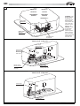
VALVOLA 4X2
4X2 VALVE
FUNZIONAMENTO
ESTIVO
SUMMER OPERATING
MODE
ATTENZIONE$OILQH
di evitare fenomeni
di trafilamento, la
massima differenza
di pressione fra il
circuito idraulico lato
caldo e quello lato
freddo deve essere
inferiore a 1 bar.
VALVOLA CIRCUITO FREDDO
COLD CIRCUIT VALVE
VALVOLA CIRCUITO CALDO
HOT CIRCUIT VALVE
IN
USCITA ACQUA
WATER OUTLET
OUT
INGRESSO ACQUA
WATER INLET
WARNING: In order
to avoid leakage
problems, the
maximum pressure
difference between
the hot side and the
cold side of the water
circuit should be
lower than 1 bar.
2
IWC 03-04-05
IWC 03-04-05
VALVOLA 4X2
4X2 VALVE
FUNZIONAMENTO
INVERNALE
WINTER MODE
OPERATION
ATTENZIONE$OILQH
di evitare fenomeni
di trafilamento, la
massima differenza
di pressione fra il
circuito idraulico lato
caldo e quello lato
freddo deve essere
inferiore a 1 bar.
VALVOLA CIRCUITO FREDDO
COLD CIRCUIT VALVE
VALVOLA CIRCUITO CALDO
HOT CIRCUIT VALVE
USCITA ACQUA
WATER OUTLET
WARNING: In order
to avoid leakage
problems, the
maximum pressure
difference between
the hot side and the
cold side of the water
circuit should be
lower than 1 bar.
IN
OUT
INGRESSO ACQUA
WATER INLET
3
IWC 06-08-10
IWC 06-08-10
VALVOLA 4X2
4X2 VALVE
FUNZIONAMENTO
ESTIVO
SUMMER OPERATING
MODE
VALVOLA CIRCUITO FREDDO
COLD CIRCUIT VALVE
USCITA ACQUA
WATER OUTLET
IN
OUT
INGRESSO ACQUA
WATER INLET
VALVOLA CIRCUITO CALDO
HOT CIRCUIT VALVE
WC66000101 - Rev 04
ATTENZIONE$OILQH
di evitare fenomeni
di trafilamento, la
massima differenza
di pressione fra il
circuito idraulico lato
caldo e quello lato
freddo deve essere
inferiore a 1 bar.
WARNING: In order
to avoid leakage
problems, the
maximum pressure
difference between
the hot side and the
cold side of the water
circuit should be
lower than 1 bar.
È severamente vietata la riproduzione anche parziale di questo manuale / All copying, even partial, of this manual is strictly forbidden
31
IWC
4
IWC 06-08-10
IWC 06-08-10
VALVOLA 4X2
4X2 VALVE
FUNZIONAMENTO
INVERNALE
WINTER MODE
OPERATION
ATTENZIONE$OILQH
di evitare fenomeni
di trafilamento, la
massima differenza
di pressione fra il
circuito idraulico lato
caldo e quello lato
freddo deve essere
inferiore a 1 bar.
VALVOLA CIRCUITO FREDDO
COLD CIRCUIT VALVE
USCITA ACQUA
WATER OUTLET
IN
OUT
INGRESSO ACQUA
WATER INLET
VALVOLA CIRCUITO CALDO
HOT CIRCUIT VALVE
WARNING: In order
to avoid leakage
problems, the
maximum pressure
difference between
the hot side and the
cold side of the water
circuit should be
lower than 1 bar.
IWC 03-04 4 TUBI, IWC 03-04 4 PIPES
Valvola a 2 vie - 2-Way valve
Uscita acqua
batteria principale
Main heat exchanger
water outlet
Ingresso acqua
batteria principale
Main heat exchanger
water inlet
Uscita acqua
batteria addizionale
Additional heat
exchanger water outlet
Ingresso acqua
batteria addizionale
Additional heat
exchanger water inlet
IWC 03-04-05 2 TUBI, IWC 03-04-05 2 PIPES
Valvola a 2 vie - 2-Way valve
Uscita acqua
Water outlet
Ingresso acqua
Water inlet
32
È severamente vietata la riproduzione anche parziale di questo manuale / All copying, even partial, of this manual is strictly forbidden
WC66000101 - Rev 04
IWC
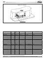
IWC 06-08-10 2 TUBI, IWC 06-08-10 2 PIPES
Valvola a 2 vie - 2-Way valve
Uscita acqua
Water outlet
Ingresso acqua
Water inlet
Codice Kit - Valve Kit Code
Unità - Unit
Versione Version
Valvola - Valve Type
Attuatore - Actuator
Attacchi Idraulici - Water connections
IWYVK2V04410
IWC03-04
4 tubi-pipes
2 vie-way
230 V - ON/OFF
1/2" Gas-F
IWYVK2V04420
IWC03-04
4 tubi-pipes
2 vie-way
Modulante-Modulating 0-10V
1/2" Gas-F
IWYVK2V04430
IWC03-04
4 tubi-pipes
2 vie-way
24V - ON/OFF
1/2" Gas-F
IWYVK2V05210
IWC03-04-05
2 tubi-pipes
2 vie-way
230 V - ON/OFF
1/2" Gas-F
IWYVK2V05220
IWC03-04-05
2 tubi-pipes
2 vie-way
Modulante-Modulating 0-10V
1/2" Gas-F
IWYVK2V05230
IWC03-04-05
2 tubi-pipes
2 vie-way
24V - ON/OFF
1/2" Gas-F
IWYVK2V10210
IWC06-08-10
2 tubi-pipes
2 vie-way
230 V - ON/OFF
3/4" Gas-F
IWYVK2V10220
IWC06-08-10
2 tubi-pipes
2 vie-way
Modulante-Modulating 0-10V
3/4" Gas-F
IWYVK2V10230
IWC06-08-10
2 tubi-pipes
2 vie-way
24V - ON/OFF
3/4" Gas-F
IWYVK3V04410
IWC03-04
4 tubi-pipes
3 vie-way
230 V - ON/OFF
1/2" Gas-F
IWYVK3V04420
IWC03-04
4 tubi-pipes
3 vie-way
Modulante-Modulating 0-10V
1/2" Gas-F
IWYVK3V04430
IWC03-04
4 tubi-pipes
3 vie-way
24V - ON/OFF
1/2" Gas-F
IWYVK3V05210
IWC03-04-05
2 tubi-pipes
3 vie-way
230 V - ON/OFF
1/2" Gas-F
IWYVK3V05220
IWC03-04-05
2 tubi-pipes
3 vie-way
Modulante-Modulating 0-10V
1/2" Gas-F
IWYVK3V05230
IWC03-04-05
2 tubi-pipes
3 vie-way
24V - ON/OFF
1/2" Gas-F
IWYVK3V10210
IWC06-08-10
2 tubi-pipes
3 vie-way
230 V - ON/OFF
3/4" Gas-F
IWYVK3V10220
IWC06-08-10
2 tubi-pipes
3 vie-way
Modulante-Modulating 0-10V
3/4" Gas-F
IWYVK3V10230
IWC06-08-10
2 tubi-pipes
3 vie-way
24V - ON/OFF
3/4" Gas-F
IWY4K3V05210
IWC03-04-05
2 tubi-pipes
3 vie-way
230 V - ON/OFF
µ*DV)
IWY4K3V05220
IWC03-04-05
2 tubi-pipes
3 vie-way
Modulante-Modulating 0-10V
µ*DV)
IWY4K3V05230
IWC03-04-05
2 tubi-pipes
3 vie-way
24V - ON/OFF
µ*DV)
IWY4K3V10210
IWC06-08-10
2 tubi-pipes
3 vie-way
230 V - ON/OFF
µ*DV)
IWY4K3V10220
IWC06-08-10
2 tubi-pipes
3 vie-way
Modulante-Modulating 0-10V
µ*DV)
IWY4K3V10230
IWC06-08-10
2 tubi-pipes
3 vie-way
24V - ON/OFF
µ*DV)
I modelli dotati di telecomando ad infrarossi, possono montare esclusivamente un kit valvole motorizzato con attuatore a 230 Volt
All models provided with infrared remote control can mount the 230 volt valve kit motors only.
WC66000101 - Rev 04
È severamente vietata la riproduzione anche parziale di questo manuale / All copying, even partial, of this manual is strictly forbidden
33
IWC
7 - ACCENSIONE
7 - ACCENSIONE
IMPORTANTE
IMPORTANT
Prima di effettuare qualsiasi intervento sul climatizzatore,
assicurarsi di aver tolto la corrente. Gli interventi devono
essere effettuati da personale abilitato ad operare su questo
tipo di climatizzatore.
Before doing any work on the air conditioner, make sure it
is switched off and put out of bounds. Any work must be
carried out by personnel qualified and authorised to work on
this type of air conditioner.
7.1 - CONTROLLI PRELIMINARI
7.1 - PRELIMINARY CHECKS
7.2 - METTERE L’UNITÀ IN TENSIONE
7.2 - SWITCH ON THE UNIT
$VVLFXUDUVL
- della stabilità dell’unità,
- della buona tenuta dei cavi elettrici sui loro morsetti di collegamento (se
non sono ben serrati, i morsetti possono provocare il surriscaldamento
della morsettiera),
- che i cavi elettrici siano isolati dalla lamiera o da qualsiasi parte
metallica che possa danneggiarli,
- del collegamento a terra,
- che non ci siano arnesi o altri oggetti estranei nelle unità,
- che il filtro sia ben installato,
- che la batteria sia pulita,
- del corretto serraggio dei raccordi idraulici,
- che lo scarico condensa sia ben raccordato,
- che la vaschetta di recupero della condensa sia pulita,
- che i tubi di evacuazione siano solidamente fissati.
0DNHVXUH
- that the air handler is well fixed,
- that the power cables are well fixed to their connection terminals,
- that the electric cables are properly insulated from any pieces of sheet
or metal parts which could damage them,
- that the unit is connected to earth,
- that no tools or any other objects have been left in the unit,
- that the filter is correctly fitted,
- that the coil is clean,
- the hydraulic couplings are correctly tightened,
- that the condensate discharge outlet is correctly connected,
- that the condensate drain pan is clean,
- that the condensate discharge outlet pipes are securely fastened.
3HUPH]]RGLXQGLVSRVLWLYRGLSURWH]LRQHHGLVH]LRQDPHQWR
$YYLDUHO·XQLWjFRQLOVXRFRPDQGR
$VVLFXUDUVL FKH LO YHQWLODWRUH IXQ]LRQL FRUUHWWDPHQWH DOOH WUH YHORFLWj GL
ventilazione, senza rumore meccanico anormale.
8VLQJWKHLVRODWLRQDQGSURWHFWLRQGHYLFH
6WDUWWKHGHYLFHXVLQJWKHFRQWUROER[
&KHFN WKDW WKH IDQ RSHUDWHV FRUUHFWO\ DW WKH WKUHH YHQWLODWLRQ VSHHGV
without abnormal mechanical noise.
7.3 - RIEMPIRE IL CIRCUITO IDRAULICO
7.3 - FILLING THE HYDRAULIC CIRCUIT WITH WATER
1HOFDVRLQFXLXQDYDOYRODPRWRUL]]DWDYHQJDPRQWDWDDVVLFXUDUVLGHO
suo funzionamento azionandola tramite il comando a distanza.
9HULILFDUHFKHWXWWLLUDFFRUGLVLDQRDWHQXWD
9HULILFDUHLOIXQ]LRQDPHQWRGHOODSRPSDVFDULFRFRQGHQVDYHUVDQGRXQ
po’ d’acqua nella bacinella ausiliaria posto sotto la valvola.
9HULILFDUHFKHQRQYLVLDULWRUQRG·DFTXDDOO·DUUHVWRGHOODSRPSD
6FDULFDUHO·DULDGDOORVFDPELDWRUHGHOODFDVVHWWD
34
,I D FRQWURO YDOYH LV DVVHPEOHG PDNH VXUH WKDW LW RSHUDWHV FRUUHFWO\
activating it by using the remote control.
&KHFNWKDWDOOWKHFRQQHFWLRQVDUHZDWHUWLJKW
&KHFN WKDW WKH FRQGHQVDWH SXPS RSHUDWHV FRUUHFWO\ E\ SRXULQJ D OLWWOH
water into the auxiliary drain pan under the valve.
&KHFNWKDWWKHUHLVQRZDWHUEDFNIORZZKHQWKHSXPSLVVWRSSHG
3XUJHWKHFDVVHWWH
È severamente vietata la riproduzione anche parziale di questo manuale / All copying, even partial, of this manual is strictly forbidden
WC66000101 - Rev 04
IWC
7.4 - REGOLAZIONE DEL FLUSSO D’ARIA
7.4 - ADJUSTING THE AIR FLOW DIRECTION
Il frontale è dotato di 4 deflettori regolabili per orientare il flusso d’aria.
Scegliere la posizione in accordo alla modalità di funzionamento ed
all’inclinazione consigliata.
You can adjust the air flow direction using the 4 flaps of the grille
frame. Chose the best position according ti the operation mode and the
recommended flap position.
INCLINAZIONE CONSIGLIATA DEL DEFLETTORE
RECOMMENDED FLAP POSITION
DEFLETTORI
FLAPS
Zona «A» per il raffreddamento e deumidificazione
Zone «A» for cooling and dehumidifyng
Zona «B» per il riscaldamento
Zone «B»for heating
MODELLI CON TELECOMANDO
Nei modelli dotati di telecomando ad infrarossi la posizione del deflettore è
regolata tramite il pulsante FLAP del telecomando.
Fissa:
6 posizioni
Oscillazione
continua
Oscillazione
automatica
NOTA
Il deflettore si chiude automaticamente quando il sistema è
spento.
Durante il funzionamento di riscaldamento, la velocità della
ventola è spenta e il deflettore è in posizione fissa. Quando
l’aria si è riscaldata, la posizione del deflettore e la velocità
della ventola cambiano secondo le regolazioni specificate
con il telecomando.
PRECAUZIONE
Usate il pulsante FLAP sul telecomando per regolare la posizione
del deflettore. Se spostate il deflettore a mano, la posizione del
deflettore secondo il telecomando e la posizione reale potrebbero
non corrispondere. Se ciò accadesse spegnete il sistema, aspettate
che il deflettore si chiuda e poi accendete di nuovo il condizionatore;
ora la posizione del deflettore è di nuovo normale.
Non orientare il deflettore verso il basso durante il funzionamento
di raffreddamento. La condensa può iniziare a formarsi attorno
all’uscita dell’aria causando un gocciolamento.
WC66000101 - Rev 04
MODELS WITH REMOTE CONTROL UNIT
In case of models with remote control unit, you can adjust the flap
position using the FLAP button on the remote contro unit.
Fixed:
6 position
Continous
oscillations
Automatically
oscillations
NOTE
The flap automatically closes when the system is off.
During heating operation, the fan is off and the flap is in
fixed position. Once the air warms up, the flap position and
fan speed change according to the settings specified with
the remote control.
CAUTION
Use the FLAP button on the remote control to adjust the position
of the flap. If you move the flap by hand, the factual flap position
and the flap position on the remote control may no longer match.
If this should happen, switch off the unit, wait for the flap to close,
and then turn on the unit again; the flap position will now be
normal again.
Do not have the flap pointed down during cooling operation.
Condensation may begin to form around the air vent and drip
down.
È severamente vietata la riproduzione anche parziale di questo manuale / All copying, even partial, of this manual is strictly forbidden
35
IWC
8 - NOME DELLE PARTI E TELECOMANDO
8 - NAME OF PARTS AND REMOTE CONTROL UNIT
15
14
12
6
13
10
3
1
2
5
11
4
5
7
9
8
6
5
OPER TIMER STBY
7
1.
2.
Telecomando.
Sensore telecomando: rileva la temperatura ambiente attorno al telecomando, il
condizionatore è regolato dalla temperatura rilevata.
Mandata aria: distribuisce l’aria trattata nel locale.
5LSUHVDDULDO·DULDDPELHQWHYLHQHDVSLUDWDHSDVVDDWWUDYHUVRLOILOWURFKHWUDWWLHQHOD
polvere.
Ricevitore: riceve i segnali inviati dal telecomando a raggi infrarossi (Trasmettitore).
Selettore funzionamento (senza telecomando): Premere questo tasto per passare da
una funzione all’altra (OFF, COOL e HEAT).
3.
4.
5.
6.
AVVERTIMENTO: La posizione OFF non interrompe l’alimentazione elettrica. Usate
l’interruttore principale per isolare il condizionatore d’aria.
7.
8.
9.
10.
11.
12.
13.
14.
15.
Spia funzionamento (OPERATION): si accende quando l’unità è in funzione. Lampeggia
XQDYROWDSHUDYYLVDUHFKHLOVHJQDOHGHOWHOHFRPDQGRpVWDWRULFHYXWRHPHPRUL]]DWR
Lampeggia continuamente durante le funzioni di protezione (sbrinamento, ecc.).
Spia attesa (STANDBY):6LDFFHQGHTXDQGRLOFRQGL]LRQDWRUHpFROOHJDWRDOODFRUUHQWH
HGpSURQWRDULFHYHUHLOVHJQDOHGDOWHOHFRPDQGR
Spia TIMER: si accende quando l’unità è controllata dal timer.
Fermo di chiusura griglia di aspirazione, su due lati.
Filtro aria.
Staffe di appensione.
Attacchi frigoriferi.
Attacco scarico condensa.
Sensore: ULOHYD OD WHPSHUDWXUD DPELHQWH DWWRUQR DOO·XQLWj TXDQGR LO WHOHFRPDQGR p
inattivo il condizionatore sarà regolato dalla temperatura rilevata.
NOTA: Il lampeggio contemporaneo delle 3 spie OPERATION, TIMER e STANDBY, indica
che il modo di funzionamento selezionato non é compatibile con l’unità in oggetto. Se
ciò accade il condizionatore non funziona fino al ripristino della modalità corretta.
LUOGO D'INSTALLAZIONE
Si raccomanda di far installare questo condizionatore d’aria da un tecnico
qualificato seguendo le istruzioni di installazione allegate.
1.
2.
9
8
Remote control unit.
Remote control sensor: Detects the room temperature around the remote control unit,
the air conditioner is controlled accordingly.
Air outlet: Conditioned air is blown out of the air conditioner through the air outlet.
Air intake: Air from the room is drawn into this section and passes through air filter
which removes dust.
Remote control receiver: This section picks up infrared signals from the remote
control unit (Transmitter).
Operation selector (without remote control): Push the button to walk through the OFF,
COOL and HEAT operation modes.
3.
4.
5.
6.
WARNING: The OFF position does not disconnect the power. Use the main power switch
to turn off power completely.
7.
OPERATION lamp: This lamp lights up during operation. It blinks once to announce
that the remote control signal has been received and stored. It blinks continuously
during the protection modes (defrosting, etc.).
8.
STANDBY lamp: This lamp lights up when the air conditioner is connected to the
power and ready to receive the remote control command.
TIMER lamp: This lamp lights up when the system is being controlled by the timer.
Air intake latch, on two sides.
Air filter.
Suspension brackets.
Refrigerant couplings.
Condensate drain connection.
Sensor: Detects the room temperature around the unit; when the remote control unit
is not active the air conditioner will be set by the detected temperature.
9.
10.
11.
12.
13.
14.
15.
NOTE: The blinking of OPERATION, TIMER and STANDBY lamps, indicates that the
operating mode selected is not compatible with the unit. If this happen the air
conditioner does not operate until the correct mode is selected.
INSTALLATION LOCATION
We recommend this air conditioner to be installed properly by qualified installation
technicians in accordance with the installation instructions provided with the unit.
AVVERTIMENTO
WARNING
Non installare questo condizionatore d’aria dove ci sono fumi, gas
Do not install this air conditioner where there are fumes or flammable gases, or in an
infiammabili o molta umidità, come in una serra.
Non installare il condizionatore dove ci sono apparecchiature che generano
un calore eccessivo.
Do not install the air conditioner where excessively high heat-generating objects are
Non installare l’unità interna in locali dove potrebbe essere investita da
Do not install the air conditioner where the atmosphere is extremely damp or humid
spruzzi d’acqua (es. lavanderia).
36
extremely humid space such as a green house.
placed.
(e.g. greenhouse or laundry) it could be wetted by drops of water (i.e. in laundries).
È severamente vietata la riproduzione anche parziale di questo manuale / All copying, even partial, of this manual is strictly forbidden
WC66000101 - Rev 04
IWC
REQUISITI ELETTRICI
Prima dell’installazione assicuratevi che la tensione dell’alimentazione
elettrica di rete sia uguale a quella indicata sulla targhetta del
condizionatore d’aria.
Tutti gli allacciamenti elettrici devono essere conformi alle normative
elettriche locali. Per i dettagli consultare il rivenditore o un elettricista.
Ciascuna unità deve essere collegata correttamente a massa, con un
filo di terra.
Gli allacciamenti elettrici devono essere eseguiti da un elettricista
specializzato.
ISTRUZIONI DI SICUREZZA
Leggete attentamente questo manuale prima di usare il condizionatore
d’aria. In caso di dubbi o problemi rivolgetevi al rivenditore o al centro
assistenza autorizzato.
Questo condizionatore d’aria è stato progettato per creare condizioni
climatiche ideali nella vostra stanza. Usatelo soltanto per questo scopo
specifico e come descritto in questo manuale.
AVVERTIMENTO
ELETRICAL REQUIREMENTS
Before installation, check that the voltage of the electric supply in your
home or office is the same as the voltage shown on the nameplate.
All wiring must conform to the local electrical codes. Consult your
dealer or a qualified electrician for details.
Each unit must be properly grounded with a ground (or earth) wire or
through the supply wiring.
Wiring must be done by a qualified electrician.
SAFETY INSTRUCTIONS
Read this booklet carefully before using this air conditioner. If you still
have any difficulties or problems, consult your dealer for help.
This air conditioner is designed to give you comfortable room
conditions. Use this only for its intended purpose as described in this
Instruction Manual.
WARNING
Mai usare o conservare benzina o altri liquidi infiammabili vicino al
Never use or store gasoline or other flammable vapor or liquid near the air
Non installare sotto l’unità apparecchiature elettriche non protette con grado
Never install electrical equipment, which is not protected with IPX1
Il costruttore non si assume responsabilità alcuna nel caso in cui le norme
The manufacturer assumes no responsabilities if the safety regulations or
condizionatore. È molto pericoloso.
di protezione IPX1 (protezione all’acqua a caduta verticale).
di sicurezza e antinfortunistiche non vengano rispettate.
PRECAUZIONE
conditioner. It is very dangerous.
protection (protection against vertical water drop), under the unit.
local codes are not observed.
CAUTION
Non accendete e spegnete il condizionatore d’aria mediante l’interruttore
Never use the power main switch to start or stop the air conditioner: always
Non inserite oggetti nel condizionatore. È molto pericoloso perché il
Do not stick anything into the air outlet of the air conditioner. This is
Non raffreddate eccessivamente la stanza se ci sono bambini molto piccoli
Do not let children play with the air conditioner.
Do not cool the room too much if babies or invalids are present.
generale. Usate sempre il pulsante ON/OFF sul telecomando o il selettore di
funzionamento sull’unità.
ventilatore gira ad alta velocità.
Non lasciate giocare i bambini con il condizionatore d’aria.
o degli invalidi.
USO DEL TELECOMANDO
INSERIMENTO DELLE BATTERIE
Rimuovere il coperchio sul retro del telecomando e verificare che i
TXDWWURPLFURLQWHUUXWWRULVLDQRLPSRVWDWLFRPHLQILJXUD
use the ON/OFF button on the remote control unit or the selector switch on
the unit.
dangerous because the fan is rotating at high speed.
USING THE REMOTE CONTROL UNIT
HOW TO INSTALL BATTERIES
Remove trhe lid in the rear part of the remote control unit and check the
VHWWLQJVRIWKHGLSVZLWFKDVVKRZQEHORZ
INTERRUTTORI
SWITCHES
WC66000101 - Rev 04
È severamente vietata la riproduzione anche parziale di questo manuale / All copying, even partial, of this manual is strictly forbidden
37
IWC
COME RIMUOVERE LE BATTERIE
Rimuovere il coperchio.
Premere la batteria verso il polo negativo ed estrarla dalla parte del polo
positivo (come mostrato in figura).
Rimuovere l’altra batteria allo stesso modo.
HOW TO REMOVE BATTERIES
Remove the lid.
Press the battery toward the negative end and lift it out by its positive
end (as shown in the figure).
Remove the other battery in the same way.
SELETTORE DEL SENSORE DI TEMPERATURA
In condizioni normali la temperatura ambiente viene rilevata e controllata
dal sensore di temperatura posizionato all’interno del telecomando
(icona IFEEL attiva sul display).
Questa funzione permette di creare una temperatura ambiente ottimale
SHUFKpLOWHOHFRPDQGRWUDVPHWWHODWHPSHUDWXUDGDOODSRVL]LRQHLQFXLYL
trovate. Quindi, usando questa funzione, il telecomando deve sempre
essere indirizzato verso il condizionatore.
E’ possibile disattivare il sensore di temperatura del telecomando
premendo il tasto I FEEL. In tal caso la relativa icona sul display si
spegne e diventa operativo il sensore presente all’interno dell’unità.
TEMPERATURE SENSOR SELECTOR
Under normal conditions the room temperature is detected and
checked by the temperature sensor placed in the remote controller (I
FEEL icon displayed ).
This function is designed to provide a personalised environment by
transmitting the temperature control command from the location next
to you. Therefore, when using this option, the remote control should
always be aimed, without obstruction, at the air conditioner.
It is possible to disable the remote controller room sensor pressing
the I FEEL button. In this case the I FEEL icon on the remote controller
display lights off and the sensor placed in the air conditioner becomes
active.
NOTA
NOTE
Il telecomando trasmette il segnale della temperatura ambiente alla pressione di
ogni tasto ed automaticamente ogni cinque minuti.
Se, a causa di inconvenienti, l’unità non riceve il segnale del telecomando il
condizionatore d’aria utilizza, per il controllo della temperatura ambiente,
il sensore presente all’interno dell’unità. In questi casi la temperatura vicino
al telecomando può differire dalla temperatura rilevata nella posizione del
condizionatore d’aria.
The remote control unit sends the temperature signal at any key pressing and
automatically every five minutes. If, due to some troubles, the signal from
the remote is no longer detected, the air conditioner keeps operating using
the temperature sensor of the indoor unit to control the room temperature. In
this case, the temperature around the remote control unit may differ from the
temperature detected in the air conditioner position.
FUNZIONAMENTO CON IL TELECOMANDO
Indirizzare il telecomando con la testina del trasmettitore verso il ricevitore
posto sul condizionatore d’aria.
OPERATION WITH THE REMOTE CONTROL UNIT
When using the remote control unit, always point the unit transmitter
head directly at the air conditioner receiver.
COME ACCENDERE IL CLIMATIZZATORE
Premere il tasto ON/OFF per accendere il climatizzatore. La spia
IXQ]LRQDPHQWRVLDFFHQGHUjDGLQGLFDUHFKHO·XQLWjpLQIXQ]LRQH
HOW TO TURN ON THE AIR CONDITIONER
Press the ON/OFF button to turn the air conditioner on. The operation
lamp will light up, indicating the unit is in operation.
38
È severamente vietata la riproduzione anche parziale di questo manuale / All copying, even partial, of this manual is strictly forbidden
WC66000101 - Rev 04
IWC
TELECOMANDO
VISORE Visualizza le informazioni quando il telecomando è acceso.
Indica che il climatizzatore
funziona in modalità I FEEL
(sensore telecomando attivo)
Modo di funzionamento
Automatico
Conferma trasmissione dati
al climatizzatore
Raffreddamento
Riscaldamento
Deumidificazione
Indica i tipi
di timer
Ventilazione
Orologio
Modalità
silenziosa
Oscillazione
Flap
SENSORE
Un sensore di temperatura all’interno del telecomando
rileva la temperatura ambiente.
SELETTORE SENSORE DI TEMPERATURA
Premere il pulsante I FEEL per modificare l’impostazione
del sensore di temperatura attivo ( da telecomando a
Condizionatore e viceversa).
PULSANTI SELEZIONE TEMPERATURA
TEMP - (più freddo)
Premere questo pulsante per diminuire la temperatura
selezionata.
TEMP + (più caldo)
Premere questo pulsante per aumentare la temperatura
selezionata.
PULSANTE FLAP
Premere questo pulsante per selezionare la funzione
desiderata.
Temperatura
ambiente
Temperatura
impostata
Velocità ventilatore
Automatico
Media velocità
Alta velocità
Bassa velocità
TRASMETTITORE
Quando vengono premuti i pulsanti del telecomando,
il simbolo
si accede sul visore per trasmettere
i cambiamenti della regolazione al ricevitore del
climatizzatore.
PULSANTE “NIGHT” (modalità silenziosa)
appare
Quando si preme questo pulsante il simbolo
sul visore e viene selezionata la velocità silenziosa del
ventilatore.
PULSANTE INATTIVO
PULSANTE “TIMER SEL”
Premendo il pulsante sul display viene attivata la
procedura per l’impostazione del timer.
3HU GHWWDJOL YHGHUH HVHPSLR ´REGOLAZIONE DEL
TIMERµ
PULSANTE MODO DI FUNZIONAMENTO
Premere questo pulsante per modificare il funzionamento
del condizionatore.
)LVVDSRVL]LRQL
(automatico)
Oscillazione continua
4XDQGRYLHQHVFHOWDODSRVL]LRQH´DXWRPDWLFRµ
il microcontrollore sceglie automaticamente tra
raffreddamento e riscaldamento in base alla
differenza tra la temperatura ambiente e quella
impostata sul telecomando.
Oscillazione automatica
PULSANTE ON/OFF (acceso/spento)
Il pulsante serve per mettere in funzione o arrestare il
climatizzatore.
PULSANTE “SEL TYPE”
3UHPHUHTXHVWRSXOVDQWHSHUVHOH]LRQDUHOHIXQ]LRQL
LPSRVWD]LRQHGHOO·RUD
LPSRVWD]LRQHGHOWLPHU212))
3HUGHWWDJOLYHGHUHOHVH]LRQL´&20(5(*2/$5(
/·252/2*,2µH´5(*2/$=,21('(/7,0(5µ
(riscaldamento)
Il condizionatore riscalda il locale.
(deumidificazione)
Il condizionatore riduce l’umidità dell’aria
ambiente.
(raffreddamento)
Il condizionatore raffredda l’aria abbassando la
temperatura del locale.
(ventilazione)
Il condizionatore funziona solo come ventilatore.
PULSANTE “FAN” (velocità ventilatore)
La velocità del ventilatore viene scelta
automaticamente dal microcontrollore.
Alta velocità ventilatore.
Media velocità ventilatore.
Bassa velocità ventilatore.
WC66000101 - Rev 04
PULSANTI REGOLAZIONE OROLOGIO E IMPOSTAZIONE
ORARIO TIMER
Premendo i pulsanti SET H / SET M è possibile impostare
l’ora e il timer.
3HU GHWWDJOL YHGHUH OH VH]LRQL ´&20( 5(*2/$5(
/·252/2*,2µH´5(*2/$=,21('(/7,0(5µ
È severamente vietata la riproduzione anche parziale di questo manuale / All copying, even partial, of this manual is strictly forbidden
39
IWC
REMOTE CONTROL UNIT
DISPLAY Information is displayed when the remote controller is switched on. If switched off, only the operating mode, the room temperature and the clock are shown
I FEEL mode is active
(remote controller sensor active)
Operation mode
Automatic
Cooling
Room
temperature
Displayed when transmitting data
Heating
Dehumidification
Timer modes
Fan
Clock
Silent mode
Oscillation
Flap
SENSOR
A temperature sensor inside the remote control unit
detects the room temperature.
TEMPERATURE SENSOR SELECTOR
Press the I FEEL button to modify the active setting for
room temperature detection (from remote controller to
air conditioner and viceversa)
Set point
temperature
Fan speed
Automatic
Medium speed
High speed
Low speed
TRANSMITTER
When you press the buttons of the remote control unit,
the
mark appears on the display to transmit the
setting changes to the receiver in the air conditioner.
“NIGHT” BUTTON (silent mode operation)
appears on
When you press this button, the mark
the display and the silent speed of fan is selected.
TEMPERATURE SETTING BUTTONS
TEMP - (cooler)
Press this button to decrease the set temperature.
TEMP + (warmer)
Press this button to increase the set temperature.
INACTIVE BUTTONS
PUSH-BUTTON FLAP
To press this push-button in order to select the wished
function.
)L[HGVL[SRVLWLRQ
Continous oscillations
“TIMER SEL” BUTTON
Press this button to select the type of timer to activate.
)RUGHWDLOVUHIHUWRSDUDJUDSK´6(77,1*7+(7,0(5µ
MODE SELECTOR BUTTON
Press this button to modify the air conditioner mode.
(automatic)
When this setting is selected, the air conditioner
calculates the difference between the
thermostat setting and the room temperature
DQG DXWRPDWLFDOO\ VZLWFKHV WR WKH ´FRROµ RU
´KHDWµPRGH
Automatically oscillations
ON/OFF BUTTON
This button turns the air conditioner ON and OFF.
(heating)
The air conditioner makes the room warmer.
(dry)
“SEL TYPE” BUTTON
3UHVVWKLVEXWWRQLQRUGHUWR
VHWWKHFORFN
VHWWKH212))WLPHU
)RUGHWDLOVUHIHUWRSDUDJUDSKV´6(77,1*7+(+285µ
DQG´6(77,1*7+(7,0(5µ
The air conditioner reduces the humidity in
the room.
(cooling)
The air conditioner makes the room cooler.
(fan)
The air conditioner works only as a circulation
fan.
“FAN “ BUTTON
Fan speed is automatically selected by the
microcontroller.
High speed
Medium speed
Low speed
40
TIMER AND PRESENT TIME SETTING BUTTONS
With these buttons is possible to set the clock and the
WLPHU )RU GHWDLOV UHIHU WR SDUDJUDSKV ´ 6(77,1* 7+(
+285µDQG´6(77,1*7+(7,0(5
È severamente vietata la riproduzione anche parziale di questo manuale / All copying, even partial, of this manual is strictly forbidden
WC66000101 - Rev 04
IWC
COME REGOLARE L’OROLOGIO
HOW TO SET THE PRESENT TIME
1. Premere tre volte il pulsante SEL TYPE.
L’indicazione dell’ora inizierà a lampeggiare.
2. Premere il pulsante SET H fino a visualizzare l’ora desiderata.
Premere il pulsante SET M fino a visualizzare i minuti desiderati.
L’indicazione dell’ora sul visore cesserà automaticamente di
lampeggiare dopo 10 secondi.
RAFFREDDAMENTO
1. Press the button SEL TYPE three times.
The time indication alone flashes.
2. Press the SET H button until the present time hour is displayed. Press
the SET M button until the present time minutes are displayed. The
display will automatically stop flashing.
COOLING
NOTA
Verificare che l’unità sia collegata alla rete elettrica e che la spia STANDBY
sia accesa.
1. Premere il pulsante MODE (modo di
funzionamento) fino a far apparire sul visore
il simbolo RAFFREDDAMENTO .
2. Premere il pulsante ON/OFF e mettere in
funzione il condizionatore.
3. Premere i pulsanti TEMP+/- per impostare
la temperatura desiderata (il campo di
regolazione varia tra 32 °C massimo e 10 °C
minimo).
1. Set the MODE selector to COOL .
2. Press the ON/OFF button and switch the air
condioner ON.
3. Press the TEMP. buttons to set the desired
temperature (the temperature range is between
32 °C max. and 10°C min.).
2
4
NOTE
Verify that the unit is connected to the main power and the STANDBY lamp
is light up.
2
4
3
1
THE DISPLAY SHOWS THE SELECTED
TEMPERATURE.
IL VISORE INDICHERÀ IL VALORE
DELLA TEMPERATURA SELEZIONATA.
TRASCORSI 5 SECONDI DALL’IMPOSTAZIONE DELLA
TEMPERATURA DESIDERATA IL VISORE TORNERÀ A
INDICARE LA TEMPERATURA AMBIENTE.
4. Premere il pulsante FAN per impostare la velocità ventilatore.
RISCALDAMENTO
3
1
AFTER 5 SECONDS FROM THE REQUIRED TEMPERATURE
SETTING THE DISPLAY WILL SHOW THE ROOM
TEMPERATURE AGAIN.
4. Press the FAN button to select the fan speed.
HEATING
1. Premere il pulsante MODE (modo di funzionamento) fino a far apparire
sul visore il simbolo RISCALDAMENTO
.
2. Premere il pulsante ON/OFF e mettere in funzione il condizionatore.
3. Premere i pulsanti temP+/- per impostare la temperatura desiderata (il
campo di regolazione varia tra 32 °C massimo e 10 °C minimo).
1. Set the MODE selector to HEAT
.
2. Press the ON/OFF button and switch the air condioner ON.
3. Press the TEMP. buttons to set the desired temperature (the temperature
range is between 32 °C max. and 10 °C min.).
IL VISORE INDICHERÀ IL VALORE
DELLA TEMPERATURA SELEZIONATA.
THE DISPLAY SHOWS THE SELECTED
TEMPERATURE.
TRASCORSI 5 SECONDI DALL’IMPOSTAZIONE DELLA
TEMPERATURA DESIDERATA IL VISORE TORNERÀ A
INDICARE LA TEMPERATURA AMBIENTE.
AFTER 5 SECONDS FROM THE REQUIRED TEMPERATURE
SETTING THE DISPLAY WILL SHOW THE ROOM
TEMPERATURE AGAIN.
4. Premere il pulsante FAN per impostare la velocità ventilatore.
4. Press the FAN button to select the fan speed.
NOTA
NOTE
Dopo l’attivazione della funzione riscaldamento, il ventilatore
GHOO·XQLWj LQWHUQD VL IHUPHUj 4XHVWR SHUFKp q RSHUDWLYD XQD
SURWH]LRQH ´3UHYHQ]LRQH FRUUHQWH DULD IUHGGDµ FKH DELOLWHUj LO
funzionamento del ventilatore solo dopo che lo scambiatore di
calore dell’unità interna sarà sufficientemente caldo. Durante questo
periodo la spia STANDBY rimarrà accesa.
For several minutes after the start of heating operation, the indoor
fan will stop until the indoor heat exchanger coil has warmed
up sufficiently. This is because the COLD DRAFT PREVENTION
SYSTEM is operating. During this period, the STANDBY lamp
remains lit.
WC66000101 - Rev 04
È severamente vietata la riproduzione anche parziale di questo manuale / All copying, even partial, of this manual is strictly forbidden
41
IWC
FUNZIONAMENTO IN AUTOMATICO
AUTOMATIC OPERATION
1. Premere il pulsante MODE (modo di funzionamento) fino a far apparire
sul Visore il simbolo AUTOMATICO .
2. Premere il pulsante ON/OFF e mettere in funzione il condizionatore.
3. Premere i pulsanti temp+/- per impostare la temperatura desiderata (il
campo di regolazione varia tra 32 °C massimo e 10 °C minimo).
1. Set the MODE selector to AUTO
.
2. Press the ON/OFF button and switch the air condioner ON.
3. Press the TEMP. buttons to set the desired temperature (the temperature
range is between 32 °C max. and 10 °C min.).
IL VISORE INDICHERÀ IL VALORE
DELLA TEMPERATURA SELEZIONATA.
THE DISPLAY SHOWS THE SELECTED
TEMPERATURE.
TRASCORSI 5 SECONDI DALL’IMPOSTAZIONE DELLA
TEMPERATURA DESIDERATA IL VISORE TORNERÀ A
INDICARE LA TEMPERATURA AMBIENTE.
AFTER 5 SECONDS FROM THE REQUIRED TEMPERATURE
SETTING THE DISPLAY WILL SHOW THE ROOM
TEMPERATURE AGAIN.
Il condizionatore automaticamente funzionerà passando dal funzionamento
riscaldamento in raffreddamento (o viceversa) in modo da mantenere la
temperatura impostata.
When this setting is selected, the air conditioner calculates the difference
between the thermostat setting and the room temperature and automatically
switches to the COOL or HEAT mode as appropriate.
4. Premere il pulsante FAN per impostare la velocità ventilatore.
4. Press the FAN selector button to the setting you want.
ESEMPIO: schema funzionamento in modalità
ambiente impostata a 23 gradi.
(Auto) con temperatura
ON
NOTA
Il climatizzatore cambia il modo di funzionamento (da freddo a caldo o
YLFHYHUVDDOYHULILFDUVLGLXQDGHOOHVHJXHQWLFRQGL]LRQL
- ZONA A: cambia se la temperatura varia di almeno 3°C da quella
impostata sul telecomando.
- ZONA B: cambia se la temperatura varia di almeno 1°C da quella
impostata sul telecomando dopo un’ora dallo stop del compressore.
- ZONA C: QRQ FDPELD PDL VH OD WHPSHUDWXUD QRQ YDULD SL GL &
rispetto a quella impostata sul telecomando.
42
N
Example of operation diagram in the
temperature at 23°C.
ON
(Auto) mode with the set room
ON
NOTE
The air conditioner changes the operation mode (from cool to heat or
YLFHYHUVDLIRQHRIWKHIROORZLQJFRQGLWLRQVRFFXUV
- ZONE A: changes if the difference between the room temperature
and the temperature set on the remote control unit is at least 3°C..
- ZONE B: changes if the difference between the room temperature
and the temperature set on the remote control unit is at least 1°C, one
hour after the compressor stop.
- ZONE C: never changes if the difference between the room temperature
and the temperature set on the remote control unit is no more than 1°C.
È severamente vietata la riproduzione anche parziale di questo manuale / All copying, even partial, of this manual is strictly forbidden
WC66000101 - Rev 04
IWC
DEUMIDIFICAZIONE
DEHUMIDIFYING (DRY)
1. Premere il pulsante MODE (modo di funzionamento) fino a far apparire
sul visore il simbolo DEUMIDIFICAZIONE .
1. Set the MODE button to DRY. The icon
2. Premere il pulsante ON/OFF e mettere in funzione il condizionatore.
3. Press the TEMP. buttons to set the desired temperature (the temperature
range is between 32 °C max. and 10 °C min.).
3. Premere i pulsanti temp+/- per impostare la temperatura desiderata (il
campo di regolazione varia tra 32 °C massimo e 10 °C minimo).
is displayed.
2. Press the ON/OFF button and switch the air condioner ON.
IL VISORE INDICHERÀ IL VALORE
DELLA TEMPERATURA SELEZIONATA.
THE DISPLAY SHOWS THE SELECTED
TEMPERATURE.
TRASCORSI 5 SECONDI DALL’IMPOSTAZIONE DELLA
TEMPERATURA DESIDERATA IL VISORE TORNERÀ A
INDICARE LA TEMPERATURA AMBIENTE.
AFTER 5 SECONDS FROM THE REQUIRED TEMPERATURE
SETTING THE DISPLAY WILL SHOW THE ROOM
TEMPERATURE AGAIN.
NOTA
Usare la funzione deumidificazione quando volete ridurre l’umidità
dell’aria ambiente.
NOTE
Use DRY operation when you want to reduce the humidity in the
room.
Quando la temperatura ambiente raggiunge il valore impostato sul
telecomando (termostato) il condizionatore ripete in automatico dei
cicli di acceso o spento.
Once the room temperature reaches the set level, the unit repeats the
Con la funzione deumidificazione impostata, il ventilatore
During DRY operation, the fan speed is automatically set to
automaticamente gira alla velocità
raffreddare troppo.
o si ferma per evitare di
La funzione deumidificazione non può essere attivata quando la
cycle of turning on and off automatically.
or stops to prevent overcooling.
Dry operation is not possible if the indoor temperature is 10 °C or
less.
temperatura interna è inferiore a 10 °C.
VENTILAZIONE
FAN ONLY
Se si vuole soltanto far circolare aria nel locale senza modificare la
WHPSHUDWXUDRSHUDUHFRPHVHJXH
If you want to make air circulate without any temperature control, follow
WKHVHVWHSV
1. Premere il pulsante ON/OFF e mettere in funzione il condizionatore.
1. Press the ON/OFF operation button and switch the air conditioner ON.
2. Premere il pulsante MODE (modo di funzionamento) fino a far apparire
sul visore solo il simbolo ventilazione .
2. Press MODE button until only the
SCELTA VELOCITÀ VENTILATORE
ADJUSTING THE FAN SPEED
AUTOMATICO
. Il
,PSRVWDUH FRQ LO SXOVDQWH )$1 OD SRVL]LRQH ´$8720$7,&2µ
microcontrollore controllerà automaticamente la velocità del ventilatore.
Quando il climatizzatore comincia a funzionare il sensore temperatura rileva
la differenza tra la temperatura ambiente e la temperatura impostata e la
trasmette al microcontrollore che automaticamente sceglie la velocità del
YHQWLODWRUHSLLGRQHD
DIFFERENZA TRA TEMPERATURA
AMBIENTE E TEMPERATURA IMPOSTATA
3°C e oltre
Raffreddamento,
riscaldamento e
deumidificazione
WC66000101 - Rev 04
fan sign appears on the display.
VELOCITÁ
VENTILATORE
AUTOMATIC
Simply set the FAN selector to the
position. A microcontroller
automatically controls the fan speed when the AUTO mode is selected.
When the air conditioner starts operating, the difference between the room
temperature and the set temperature is detected by the microcontroller
which then automatically switches the fan speed to the most suitable level.
WHEN DIFFERENCE BETWEEN ROOM
TEMPERATURE AND SET TEMPERATURE IS
3°C and over
Massima
Tra 3 e 2°C
Media
Tra 2 e 1°C
Minima
Meno di 1°C
Superbassa
Cooling, heating and
dehumidifying modes
FAN SPEED
High
Between 3 and 2°C
Medium
Between 2 and 1°C
Low
Below 1°C
Very low
È severamente vietata la riproduzione anche parziale di questo manuale / All copying, even partial, of this manual is strictly forbidden
43
IWC
NOTA
NOTE
I valori precisati sulla tabella si riferiscono al funzionamento del
condizionatore quando è abilitato il sensore sul telecomando (v.
selettore del sensore di temperatura).
I valori precisati variano leggermente nel caso sia abilitato il sensore
posizionato nell’unità interna.
The above mentioned data make reference to the conditioner operating
when the sensor on the remote control unit is ON. (Refer to temperature
sensor selector). If the sensor on the indoor unit is being used then
actual operation will slightly differ from that described in the above
tables.
La velocità automatica non è attiva nella modalità VENTILAZIONE.
The automatic speed is not available in FAN ONLY mode.
MANUALE
Per regolare manualmente la velocità del ventilatore agire sul pulsante FAN
VFHJOLHQGRODYHORFLWjGHVLGHUDWD
Alta velocità
Media velocità
Bassa velocità
MODALITA’ SILENZIOSA
MANUAL
If you want to manually adjust speed just set the FAN selector as desired.
High speed
Med. speed
Low speed
SILENT MODE
In questa modalità il microcontrollore imposta la velocità del ventilatore ad
un valore estremamente basso, riducendo il rumore.
1. Premere il pulsante MODE ed impostare il condizionatore in modo
raffreddamento, deumidificazione o riscaldamento.
2. Premere il pulsante NIGHT.
appare sul visore e la velocità silenziosa viene attivata.
3. Il simbolo
Per cancellare l’impostazione premere nuovamente il pulsante NIGHT.
In this mode the microcontroller forces the indoor fan to a very low speed,
in order to reduce the noise.
1. Set the MODE button to cool, dry or heat.
2. Press the NIGHT button.
symbol appears on the display and the silent speed is selected.
3. The
Press the NIGHT button again to clear this function.
NOTA
Quando viene attivata questa funzione, il simbolo sul visore della velocità
del ventilatore precedentemente selezionata, rimane invariata.
NOTE
When this function is selected, the fan speed symbol on the display, related
to the speed, previously set, remains unchanged.
44
È severamente vietata la riproduzione anche parziale di questo manuale / All copying, even partial, of this manual is strictly forbidden
WC66000101 - Rev 04
IWC
REGOLAZIONE DEL TIMER
SETTING THE TIMER
A) COME REGOLARE L’ORA DI PARTENZA (ON)
A) HOW TO SET THE ON TIME
1. Premere una sola volta il pulsante SEL TYPE.
L’indicazione ON e quelle dell’ora inizieranno a
lampeggiare.
1. Press the SEL TYPE button once. The ON and time
indications flash.
2. Premere il pulsante SET H fino a quando viene
visualizzata l’ora desiderata. Premere il pulsante
SET M fino a quando sono visualizzati i minuti
desiderati. L’indicazione sul visore ritornerà ad
indicare l’ora corrente dopo 10 secondi.
2. Press the SET H button until the designed hour
is displayed. Press the SET M button until the
designed minutes are displayed. The display will
change automatically back to show the present
time after 10 sec.
3
3. Premere il pulsante ON/OFF per mettere in funzione
il condizionatore.
4. Premere il pulsante TIMER SEL per impostare il
timer sulla funzione ON TIME (partenza).
3
3. Press the ON/OFF button to start the air conditioner.
4. Press the TIMER SEL button to activate the ON
timer.
1
2
4
B) COME REGOLARE L’ORA DI FERMATA (OFF)
1. Premere due volte il pulsante SEL TYPE.
L’ indicazione OFF e quella dell’ora inizieranno a
lampeggiare.
2. Premere il pulsante SET H fino a quando viene visualizzata l’ora
desiderata. Premere il pulsante SET M fino a quando sono visualizzati
i minuti desiderati. L’indicazione sul visore tornerà ad indicare l’ora
corrente dopo 10 secondi.
3. Premere il pulsante ON/OFF per mettere in funzione il condizionatore.
1
2
4
B) HOW TO SET THE OFF TIME
1. Press the SEL TYPE button twice. The OFF and time
indications flash.
2. Press the SET H button until the designed hour
is displayed. Press the SET M button until the
designed minutes are displayed. The display will change automatically
back to show the present time after 10 sec.
3. Press the ON/OFF button to start the air conditioner.
4. Press the TIMER SEL button two times to activate the OFF timer.
4. Premere due volte il pulsante TIMER SEL per impostare il timer sulla
IXQ]LRQH´2))7,0(µSDUWHQ]D
C) COME REGOLARE IL PROGRAMMA GIORNALIERO ACCESO/SPENTO
(O VICEVERSA)
C) HOW TO SET A PROGRAM FOR DAILY ON/OFF OPERATION (OR
VICEVERSA)
1. Regolare il timer come illustrato ai punti A e B.
1. Set the timer ON/OFF as shown in A) and B).
2. Premere il pulsante ON/OFF per mettere in funzione
il condizionatore.
2. Press the ON/OFF button to start the air conditioner.
3. Premere tre volte il pulsante TIMER SEL per impostare il programma del
timer acceso/spento o viceversa.
NOTA
3. Press three times the TIMER SELECT button to
activate the DAILY timer.
NOTE
Dopo la regolazione del timer, per verificare l’orario di impostazione in
accensione/spegnimento (ON/OFF) premere il pulsante SEL TYPE.
After timer setting, press PROGRAM button in order to check the ON/
OFF setting time.
REGOLAZIONE DEL TIMER 1 ORA
SETTING THE 1 HOUR TIME
Questa funzione permette al condizionatore di funzionare per 1 ora alle
condizioni impostate, indipendentemente se questo sia acceso o spento.
This function causes the unit to operate for one hour at the set conditions,
regardless of whether the unit is on or off.
OPERAZIONI DI IMPOSTAZIONE TIMER.
TIMER SETTING PROCEDURE.
Premere quattro volte il pulsante TIMER SEL.
Sul visore appare il simbolo del TIMER 1 ORA.
Press four times the TIMER SEL button.The 1 HOUR
TIMER mark will appear on the display.
CANCELLAZIONE DEL TIMER.
CANCELLATION PROCEDURE
3UHPHUHLOSXOVDQWH212))SHUVSHJQHUHLOFRQGL]LRQDWRUH
$WWHQGHUHFKHO·XQLWjLQWHUQDVLDVSHQWD
3UHPHUHGLQXRYRLOSXOVDQWH212))SHUULDFFHQGHUHLOFRQGL]LRQDWRUH
Press the ON/OFF button to turn the air conditioner off.
WC66000101 - Rev 04
Wait for the indoor unit to stop operating.
Press the ON/OFF button again to turn the air conditioner on.
È severamente vietata la riproduzione anche parziale di questo manuale / All copying, even partial, of this manual is strictly forbidden
45
IWC
9 - MANUTENZIONE
9 - MAINTENANCE
IMPORTANTE
Prima di effettuare qualsiasi intervento sul climatizzatore,
assicurarsi di aver tolto la corrente.
Gli interventi devono essere effettuati da personale abilitato
ad operare su questo tipo di climatizzatore.
IMPORTANT
Before doing any work on the installation, make sure it is
switched off and put out of bounds.
All operations must be carried out by personnel that are
approved and qualified for this type of equipment.
MANUTENZIONE GENERALE
l materiale deve essere sottoposto a manutenzione per conservare le sue
caratteristiche nel tempo. Un difetto di manutenzione può avere come
effetto l’annullamento della garanzia sul prodotto. Le operazioni consistono
tra l’altro e secondo i prodotti, nella pulizia dei filtri (aria, acqua), degli
scambiatori interni ed esterni, del mobile di copertura, nella pulizia e nella
protezione delle bacinelle condensa. Anche il trattamento degli odori e la
disinfezione delle superfici e dei volumi dei locali concorrono alla salubrità
dell’aria respirata dagli utilizzatori.
GENERAL MAINTENANCE
All equipment must be properly maintained in order to provide optimum
performance over time. Faulty maintenance can result in the cancellation
of the product guaranty. Depending on the products, maintenance
operations consist in the cleaning of filters (air, water), internal and external
exchangers, casings, and the cleaning and protection of condensate tanks.
Treating odours and the disinfection of room surfaces and volumes also
contributes to the cleanliness of the air breathed by users.
9.1 - PULIZIA
1RQXWLOL]]DUHPDLVROYHQWLQpSURGRWWLFKLPLFLSRWHQWL
Non pulire l’apparecchio con acqua troppo calda.
9.1 - CLEANING
1HYHUXVHVROYHQWVRUSRZHUIXOFKHPLFDOSURGXFWV
'RQRWFOHDQWKHXQLWZLWKYHU\KRWZDWHU
9.2 - FILTRO ARIA
Si raccomanda la sua pulizia una volta al mese, ma la frequenza
dipende dalle condizioni di funzionamento.
3HUWRJOLHUHLOILOWUR
- Togliere le viti (1) di bloccaggio dei fermi (2) su ogni lato.
- Per aprire la griglia (3), spingere sui due fermi (2) nel senso della freccia.
- Aprire la griglia (3) verso il basso.
- Togliere il filtro (4) dalla griglia.
3XOL]LD
- Utilizzare un aspirapolvere per togliere la polvere. Se la polvere
è incollata sul filtro, toglierla con acqua pulita o insaponata,
risciacquarlo con acqua pulita e asciugarlo.
- Ricollocare il filtro nella sua sede nella griglia, richiudere la griglia,
spostando i due fermi verso l’esterno, poi rimettere le viti di
bloccaggio dei fermi.
9.2 - AIR FILTER
,W LV UHFRPPHQGHG WR FOHDQ WKH ILOWHU RQFH D PRQWK DOWKRXJK WKH
frequency of cleaning depends on the operating conditions.
5HPRYLQJWKHILOWHU
- Remove the retaining screws (1) from the locks (2) on each side.
- To open the grille (3), push both locks (2) in the direction of the arrow.
- Open the grille (3) downwards.
- Remove the filter (4) from the grille.
&OHDQLQJ
- Use a vacuum cleaner to remove the dust. If the dust sticks to the
filter, wash it in clear or soapy water, rise with clear water and then
dry it.
- Replace the filter in its housing in the grille, close the grille by pushing
the locks toward the outside, then replace the lock retaining screws.
9.3 - GRIGLIA D’ASPIRAZIONE
/DJULJOLDSXzHVVHUHVPRQWDWDSHUHVVHUHSXOLWD
- Dopo aver aperto la griglia (1), staccare la corda di sicurezza (2) del
quadro (3) (ricordarsi di agganciarla di nuovo dopo le operazioni di
manutenzione e di pulizia).
6ROOHYDUHODJULJOLDHWLUDUODYHUVRVpSHUVJDQFLDUHOHGXHFHUQLHUH
- Pulire la griglia delicatamente utilizzando una spugna morbida, poi
asciugare bene. Per togliere le tracce difficili può essere utilizzato un
detergente neutro. Risciacquare bene con acqua poi asciugare.
9.4 - QUADRO ELETTRICO
6LUDFFRPDQGDGLHIIHWWXDUHXQDYROWDO·DQQRODVSROYHUDWXUDGHOTXDGUR
elettrico.
9HULILFDUHXQDYROWDO·DQQRODFRUUHWWDWHQXWDGHLILOLHOHWWULFLVXOOHORUR
morsettiere di collegamento.
9.3 - INTAKE GRILLE
7KHJULOOHFDQEHUHPRYHGIRUFOHDQLQJ
- After having opened the grille (1), unhook the safety cord (2) from the
frame (3) (remember to hook it back in place after the maintenance
and cleaning operations).
- Raise the grille and pull it towards you to unhook it from the two
hinges.
- Clean the grille gently using a soft sponge, then dry it thoroughly. A
neutral detergent can be used to remove stubborn areas. Thoroughly
rinse with water, then dry.
9.4 - ELECTRICAL BOX
,WLVUHFRPPHQGHGWKDWWKHHOHFWULFDOER[EHGXVWHGRQD\HDUO\EDVLV
&KHFN \HDUO\ WKDW WKH HOHFWULFDO ZLULQJ LV VHFXUHO\ KHOG LQ WKHLU
connecting terminals.
3
1
2 1
46
3
4
È severamente vietata la riproduzione anche parziale di questo manuale / All copying, even partial, of this manual is strictly forbidden
2
WC66000101 - Rev 04
IWC
9.5 - ADDITIONAL MAINTENANCE
7KH LQVSHFWLRQ FOHDQLQJ RU UHSODFHPHQW RU LQWHUQDO FRPSRQHQWV
requires that the main condensate tank be removed.
9.5 - MANUTENZIONE SUPPLEMENTARE
/·LVSH]LRQHODSXOL]LDRODVRVWLWX]LRQHGHLFRPSRQHQWLLQWHUQLQHFHVVLWD
lo smontaggio del serbatoio principale della condensa.
Attenzione: Alcuni pezzi metallici sono taglienti e possono provocare ferite.
Attention: Certain metal parts are sharp and may cause injury.
7 DQNUHPRYDO
- Remove the intake grille.
- Remove the rubber plug (1) and empty the condensed water
remaining in the tank into a bucket. Replace the plug immediately
afterward.
- Remove the facade/grille assembly (2) by unscrewing the four
retaining screws (3). The two clips (4) can be used to maintain
thefacade suspended to the unit.
- Remove the (5) which hold the two plates (6) supporting the tank (7).
- Remove the tank, grasping it by the two clips (4). Handle it carefully
as the polyethylene parts are fragile.
- Clean the inside of the tank as required, and check that the hose is
not clogged.
- Check that the heat exchanger is clean. If needed, use a vacuum
cleaner with a rubber tip to remove dust being careful not to damage
the fins.
7DQNUHSODFHPHQW
- Put the tank (7) back into place by positioning the drain plug (1) on
the pump side. Tighten the retaining screws (5).
- Put the facade (2) back in place using the two tank clips (4) to
maintain it suspended on the unit. Tighten the retaining screws (3).
- Put the grille back in place with the air filter installed.
- Hook the grille safety cord to the frame, close the grille and replace
the lock retaining screws.
6PRQWDJJLRGHOVHUEDWRLR
- Togliere la griglia d’aspirazione.
- Vuotare l’acqua di condensa che resta nel serbatoio in un secchio
togliendo il tappo di gomma (1). Ricollocarlo in sede subito dopo.
- Togliere l’insieme frontale / griglia (2) svitando le quattro viti di
fissaggio (3). Si possono utilizzare le due clip (4) per mantenere il
frontale sospeso all’apparecchio.
- Togliere le viti (5) che tengono le due piastre (6) di supporto del
serbatoio (7).
- Togliere il serbatoio afferrandolo dalle clip (4). Manipolarlo con cura
SRLFKpOHSDUWLLQSROLHWLOHQHVRQRIUDJLOL
- Pulire l’interno del serbatoio se necessario, e verificare che il tubo non
sia ostruito.
- Verificare che lo scambiatore termico sia pulito. Se necessario
spolverarlo con un aspiratore con bocchettone di gomma facendo
attenzione a non danneggiare le alette.
5LPRQWDJJLRGHOVHUEDWRLR
- Ricollocare in sede il serbatoio (7) posizionando il tappo di scarico
(1) sul lato pompa. Riavvitare le viti di fissaggio (5).
- Ricollocare in sede il frontale (2) utilizzando le due clip (4) del
serbatoio per sospenderlo all’apparecchio. Riavvitare le viti di
fissaggio (3).
- Ricollocare in sede la griglia con il filtro ad aria.
- Agganciare la corda di sicurezza della griglia al quadro, chiudere la
griglia e ricollocare le viti di bloccaggio dei fermi.
9.6 - WATER LEVEL ALARM
1RWH'XULQJQRUPDORSHUDWLRQWKHFRQGHQVDWHSXPSLVDFWXDWHGDWWKH
same time as the main exchanger valve.
,QFDVHRIDEQRUPDOEDFNIORZRIZDWHULQWRWKHFRQGHQVDWHWDQNGXHWR
a faulty pump, a dirty tank, or a plugged drain line,...), a safety contact
(floater) disconnects the remote control’s power supply and causes the
ventilation to shut down, the control valve to close and activates the
pump on a permanent basis. In case of models with remote control unit
the operation lamp is blinking.
9.6 - ALLARME LIVELLO D’ACQUA
1RWD,QIXQ]LRQDPHQWRQRUPDOHODSRPSDGHOODFRQGHQVDqD]LRQDWD
contemporaneamente alla valvola dello scambiatore principale.
,Q FDVR GL VDOLWD DQRUPDOH GHOO·DFTXD QHO VHUEDWRLR GHOOD FRQGHQVD
(dovuta alla pompa difettosa, ad un serbatoio sporco, ad un tubo
d’evacuazione ostruito, …), un contatto di sicurezza (galleggiante)
interrompe l’alimentazione del comando a distanza e provoca l’arresto
della ventilazione, la chiusura della valvola di regolazione e aziona
la pompa in permanenza. Nei modelli con telecomando la spia di
funzionamento lampeggia.
1
7
4
5
6
3
WC66000101 - Rev 04
2
È severamente vietata la riproduzione anche parziale di questo manuale / All copying, even partial, of this manual is strictly forbidden
47
48
È severamente vietata la riproduzione anche parziale di questo manuale / All copying, even partial, of this manual is strictly forbidden
Centrifugo
1
280
175
1
230 V / 1 / 50 Hz
24
250
0,014
Centrifugo
1
280
175
1
230 V / 1 / 50 Hz
24
250
0,014
nr
gir min
kW
A
nr
mm
mm
nr
l/h
mm
kW
2
1/2" gas femmina
nr
IWC034
CARATTERISTICHE
Numero tubi scambiatore per batteria addizionale
Collegamenti idraulici
Valvola spurgo aria manuale
Versione a comando con filo
nr
mm
4
1/2" gas femmina
IWC044
1
ø 70
230 V / 1 / 50 Hz
1
F
4
890
0,075
0,40
230 V / 1 / 50 Hz
1
F
4
620
0,040
0,25
nr
1
ø 70
0,272
1,3
0,86
1/2" gas femmina
mm
l
m2
0,255
0,272
1,6
1,3
0,66
0,43
1/2" gas femmina
IWC042
Acciaio galvanizzato
3 esterno
Polistirene
RAL 9010
IP 20
IWC034
Acciaio galvanizzato
3 esterno
Polistirene
RAL 9010
IP 20
mm
IWC032
MODELLO CON BATTERIA ADDIZIONALE (4 tubi)
CARATTERISTICHE COSTRUTTIVE
Materiale
Isolamento in polietilene (spessore)
Materiale pannello / griglia
Colore pannello / griglia
Protezione scatola elettrica
SCAMBIATORE TERMICO RAME / ALLUMINIO
Superficie frontale
Passo alette
Contenuto acqua
Collegamenti idraulici
Valvola spurgo aria manuale
MOTORE VENTILATORE
Alimentazione
Numero
Protezione termica interna
Classe
Numero di poli
Numero di giri (alta velocità)
Potenza assorbita massima
Intensità assorbita massima
VENTILATORE
Tipo
Numero
Diametro
Altezza
FILTRO ARIA
Polipropilene classe HB (UL 94) lavabile
Numero
POMPA SCARICO CONDENZA
Alimentazione
Portata nominale
Altezza di sollevamento sopra l'apparecchio
Potenza assorbita
ARIA DI RINNOVO (PREDISPOSIZIONE)
Numero prese
Dimensioni di collegamento
Versione a comando con filo
Versione a telecomando infrarossi
MODELLO
1
ø 70
230 V / 1 / 50 Hz
24
250
0,014
1
Centrifugo
1
280
175
230 V / 1 / 50 Hz
1
B
4
1080
0,087
0,39
0,272
1,3
0,86
1/2" gas femmina
Acciaio galvanizzato
3 esterno
Polistirene
RAL 9010
IP 20
IWC052
1
60 x 55
230 V / 1 / 50 Hz
36
250
0,015
1
Centrifugo
1
450
160
230 V / 1 / 50 Hz
1
A
6
440
0,115
0,5
0,349
1,5
1
3/4" gas femmina
Acciaio galvanizzato
3 esterno
Polistirene
RAL 9010
IP 20
IWC062
1
60 x 55
230 V / 1 / 50 Hz
36
250
0,015
1
Centrifugo
1
450
200
230 V / 1 / 50 Hz
1
A
6
470
0,140
0,6
0,556
1,5
1,5
3/4" gas femmina
Acciaio galvanizzato
3 esterno
Polistirene
RAL 9010
IP 20
IWC082
1
60 x 55
230 V / 1 / 50 Hz
36
250
0,015
1
Centrifugo
1
450
200
230 V / 1 / 50 Hz
1
A
6
510
0,180
0,8
0,556
1,5
1,5
3/4" gas femmina
Acciaio galvanizzato
3 esterno
Polistirene
RAL 9010
IP 20
IWC102
IWC
10 - TABELLA DATI TECNICI
WC66000101 - Rev 04
WC66000101 - Rev 04
1
230 V / 1 / 50 Hz
24
250
0,014
1
230 V / 1 / 50 Hz
24
250
0,014
nr
mm
mm
nr
l/h
mm
kW
2
1/2" gas female
nr
IWC034
CHARACTERISTICS
Numer of tubes of additional heat exchanger
Connectinos size of additional heat exchanger
Air purge valve
Wired remote controller option
nr
mm
4
1/2" gas female
IWC044
1
ø 70
Centrifugal
1
280
175
Centrifugal
1
280
175
nr
giri/min
kW
A
1
ø 70
230 V / 1 / 50 Hz
1
F
4
890
0,075
0,40
nr
mm
l
230 V / 1 / 50 Hz
1
F
4
620
0,040
0,25
Galvanized steel
3
Polystyrene
RAL 9010
IP 20
IWC042
0,272
1,3
0,86
1/2" gas female
Galvanized steel
3
Polystyrene
RAL 9010
IP 20
IWC034
0,255
0,272
1,6
1,3
0,66
0,43
1/2" gas female
m2
mm
IWC032
MODEL WITH ADDITIONAL HEAT EXCHANGER
MECHANICAL CHARACTERISTICS
Material
Polyethylene insulation thickness (outside)
Grille mateiral
Grille color
Electrical box IP protection
HEAT EXCHANGER
Face area
Fin pitch
Water content
Connections size
Air purge valve
FAN MOTOR
Power supply
Quantity
Termal protection
Insulation class
Number of poles
Rotation speed
Max power input
Max current input
FAN
Type
Quantity
Outside diameter
Height
AIR FILTER
Polypropylene HB grade (UL 94) washable
Quantity
DRAIN PUMP
Power supply
Flow rate
Head
Power input
FRESH AIR INTAKE PORT
Quantity
Dimensions
Wired remote controller option
Wireless remote controller option
MODEL
1
ø 70
230 V / 1 / 50 Hz
24
250
0,014
1
Centrifugal
1
280
175
230 V / 1 / 50 Hz
1
B
4
1080
0,087
0,39
0,272
1,3
0,86
1/2" gas female
Galvanized steel
3
Polystyrene
RAL 9010
IP 20
IWC052
1
60 x 55
230 V / 1 / 50 Hz
36
250
0,015
1
Centrifugal
1
450
160
230 V / 1 / 50 Hz
1
A
6
440
0,115
0,5
0,349
1,5
1
3/4" gas female
Galvanized steel
3
Polystyrene
RAL 9010
IP 20
IWC062
1
60 x 55
230 V / 1 / 50 Hz
36
250
0,015
1
Centrifugal
1
450
200
230 V / 1 / 50 Hz
1
A
6
470
0,140
0,6
0,556
1,5
1,5
3/4" gas female
Galvanized steel
3
Polystyrene
RAL 9010
IP 20
IWC082
1
60 x 55
230 V / 1 / 50 Hz
36
250
0,015
1
Centrifugal
1
450
200
230 V / 1 / 50 Hz
1
A
6
510
0,180
0,8
0,556
1,5
1,5
3/4" gas female
Galvanized steel
3
Polystyrene
RAL 9010
IP 20
IWC102
IWC
10 - TECHNICAL DATA
È severamente vietata la riproduzione anche parziale di questo manuale / All copying, even partial, of this manual is strictly forbidden
49
IWC
NOTES
50
È severamente vietata la riproduzione anche parziale di questo manuale / All copying, even partial, of this manual is strictly forbidden
WC66000101 - Rev 04
IWC
NOTES
WC66000101 - Rev 04
È severamente vietata la riproduzione anche parziale di questo manuale / All copying, even partial, of this manual is strictly forbidden
51
www.galletti.it
40010 Bentivoglio (BO) Via Romagnoli 12/a Tel. 051/8908111 - Fax. 051/8908122
Azienda certificata UNI EN ISO 9001 e OHSAS 18001 / Company UNI EN ISO 9001 and OHSAS 18001 certified