1
D
BEDIENUNGSANLEITUNG
3
GB
INSTRUCTIONS MANUAL
24
F
INSTRUCTIONS D'EMPLOI
45
I
istruzioni d'uso
66
PC -540HY
000238.07
01/12/05
D
HAUPTELEMENTE DER ELEKTRISCHEN ANLAGE . . . . . . . . . . . . . . . . . . . . . . . . . . . . . . . . . . . . . . . 3
RATSCHLÄGE UND KONTROLLEN . . . . . . . . . . . . . . . . . . . . . . . . . . . . . . . . . . . . . . . . . . . . . . . . . . . . 3
KONTROLLPANEEL“PC-540HY” . . . . . . . . . . . . . . . . . . . . . . . . . . . . . . . . . . . . . . . . . . . . . . . . . . . . . . 4
KUNDENPROGRAMMIERUNG . . . . . . . . . . . . . . . . . . . . . . . . . . . . . . . . . . . . . . . . . . . . . . . . . . . . . . . 12
RELAISBOX “DS-540HY”. . . . . . . . . . . . . . . . . . . . . . . . . . . . . . . . . . . . . . . . . . . . . . . . . . . . . . . . . . . . 14
12V VERTEILERMODUL “DS-340HY” . . . . . . . . . . . . . . . . . . . . . . . . . . . . . . . . . . . . . . . . . . . . . . . . . 16
MASTER ALARMANLAGE (OPTIONAL) . . . . . . . . . . . . . . . . . . . . . . . . . . . . . . . . . . . . . . . . . . . . . . . . 18
ELEKTRONISCHES BATTERIELADEGERÄT “A2018” . . . . . . . . . . . . . . . . . . . . . . . . . . . . . . . . . . . . . 19
ZUSATZ-PANELE . . . . . . . . . . . . . . . . . . . . . . . . . . . . . . . . . . . . . . . . . . . . . . . . . . . . . . . . . . . . . . . . . . . . 21
FERNBEDIENUNG (OPTIONAL) . . . . . . . . . . . . . . . . . . . . . . . . . . . . . . . . . . . . . . . . . . . . . . . . . . . . . . 23
EINBAUPLAN . . . . . . . . . . . . . . . . . . . . . . . . . . . . . . . . . . . . . . . . . . . . . . . . . . . . . . . . . . . . . . . . . . . . . . . 87
GB
MAIN PARTS OF THE ELECTRICAL SYSTEM . . . . . . . . . . . . . . . . . . . . . . . . . . . . . . . . . . . . . . . . . . . . . 24
ADVICE AND CHECKS. . . . . . . . . . . . . . . . . . . . . . . . . . . . . . . . . . . . . . . . . . . . . . . . . . . . . . . . . . . . . . . . 24
“PC-540HY ” CONTROL PANEL . . . . . . . . . . . . . . . . . . . . . . . . . . . . . . . . . . . . . . . . . . . . . . . . . . . . . . 25
USER’S SETTINGS . . . . . . . . . . . . . . . . . . . . . . . . . . . . . . . . . . . . . . . . . . . . . . . . . . . . . . . . . . . . . . . . . . . 33
“DS-540HY” DISTRIBUTION BOARD . . . . . . . . . . . . . . . . . . . . . . . . . . . . . . . . . . . . . . . . . . . . . . . . . 35
“DS-340HY DISTRIBUTION BOARD”. . . . . . . . . . . . . . . . . . . . . . . . . . . . . . . . . . . . . . . . . . . . . . . . . . 37
MASTERALARM (OPTIONAL) . . . . . . . . . . . . . . . . . . . . . . . . . . . . . . . . . . . . . . . . . . . . . . . . . . . . . . . . . 39
BATTERY CHARGER “A2018” . . . . . . . . . . . . . . . . . . . . . . . . . . . . . . . . . . . . . . . . . . . . . . . . . . . . . . . . . 40
CONTROL PANELS . . . . . . . . . . . . . . . . . . . . . . . . . . . . . . . . . . . . . . . . . . . . . . . . . . . . . . . . . . . . . . . . . . 42
REMOTE CONTROL (OPTIONAL) . . . . . . . . . . . . . . . . . . . . . . . . . . . . . . . . . . . . . . . . . . . . . . . . . . . . . . 44
INSTALLATION . . . . . . . . . . . . . . . . . . . . . . . . . . . . . . . . . . . . . . . . . . . . . . . . . . . . . . . . . . . . . . . . . . . . . . 87
F
ELEMENTS PRINIPAUX DU SYSTEME ELECTRIQUE . . . . . . . . . . . . . . . . . . . . . . . . . . . . . . . . . . . . . . 45
CONSEILS ET CONTROLES . . . . . . . . . . . . . . . . . . . . . . . . . . . . . . . . . . . . . . . . . . . . . . . . . . . . . . . . . . . 45
PANNEAU DE COMMANDE “PC-540HY”. . . . . . . . . . . . . . . . . . . . . . . . . . . . . . . . . . . . . . . . . . . . . . 46
PROGRAMMATION UTILISATEUR . . . . . . . . . . . . . . . . . . . . . . . . . . . . . . . . . . . . . . . . . . . . . . . . . . . . . 54
TABLEAU DE DISTRIBUTION “DS-540HY” . . . . . . . . . . . . . . . . . . . . . . . . . . . . . . . . . . . . . . . . . . . . . 56
TABLEAU DE DISTRIBUTION “DS-340HY” . . . . . . . . . . . . . . . . . . . . . . . . . . . . . . . . . . . . . . . . . . . . 58
MASTER ANTIVOL (OPTIONELLE) . . . . . . . . . . . . . . . . . . . . . . . . . . . . . . . . . . . . . . . . . . . . . . . . . . . . . 60
CHARGEUR DE BATTERIES “A2018”. . . . . . . . . . . . . . . . . . . . . . . . . . . . . . . . . . . . . . . . . . . . . . . . . . . 61
PANNEAU DE COMMANDE . . . . . . . . . . . . . . . . . . . . . . . . . . . . . . . . . . . . . . . . . . . . . . . . . . . . . . . . . . 63
TELECOMMANDE (OPTIONELLE). . . . . . . . . . . . . . . . . . . . . . . . . . . . . . . . . . . . . . . . . . . . . . . . . . . . . . 65
SCHEMA D’INSTALLATION . . . . . . . . . . . . . . . . . . . . . . . . . . . . . . . . . . . . . . . . . . . . . . . . . . . . . . . . . . . 87
I
ELEMENTI PRINCIPALI DEL SISTEMA ELETTRICO. . . . . . . . . . . . . . . . . . . . . . . . . . . . . . . . . . . . . . . . 66
CONSIGLI E VERIFICHE . . . . . . . . . . . . . . . . . . . . . . . . . . . . . . . . . . . . . . . . . . . . . . . . . . . . . . . . . . . . . . 66
PANNELLO COMANDO “PC-540HY” . . . . . . . . . . . . . . . . . . . . . . . . . . . . . . . . . . . . . . . . . . . . . . . . . 67
PROGRAMMAZIONE UTENTE . . . . . . . . . . . . . . . . . . . . . . . . . . . . . . . . . . . . . . . . . . . . . . . . . . . . . . . . 75
QUADRO DISTRIBUZIONE “DS-540HY” . . . . . . . . . . . . . . . . . . . . . . . . . . . . . . . . . . . . . . . . . . . . . . 77
QUADRO DISTRIBUZIONE “DS-340HY” . . . . . . . . . . . . . . . . . . . . . . . . . . . . . . . . . . . . . . . . . . . . . . 79
MASTER ANTIFURTO (OPTIONAL) . . . . . . . . . . . . . . . . . . . . . . . . . . . . . . . . . . . . . . . . . . . . . . . . . . . . 81
CARICA BATTERIE “A2018” . . . . . . . . . . . . . . . . . . . . . . . . . . . . . . . . . . . . . . . . . . . . . . . . . . . . . . . . . . . 82
PANNELLI COMANDO . . . . . . . . . . . . . . . . . . . . . . . . . . . . . . . . . . . . . . . . . . . . . . . . . . . . . . . . . . . . . . . 84
TELECOMANDO (OPTIONAL). . . . . . . . . . . . . . . . . . . . . . . . . . . . . . . . . . . . . . . . . . . . . . . . . . . . . . . . . 86
SCHEMA DI INSTALLAZIONE . . . . . . . . . . . . . . . . . . . . . . . . . . . . . . . . . . . . . . . . . . . . . . . . . . . . . . . . . 87
2
u
u
u
u
u
u
u
u
u
u
u
HAUPTELEMENTE DER ELEKTRISCHEN ANLAGE
KONTROLLPANEEL “PC-540HY” - Steuerung der Verbraucher, Batterie-Test, Tanks-Test, Alarme.
12V RELAISBOX “DS-540HY” - Hauptrelais, Fahrzeug-Batterie (B1) Ladungseinrichtung,
Schutztsicherungen.
12V VERTEILERMODUL “DS-340HY” - Parallelbatterie-Relais (12V-70A), Trittstufen-Relais,
Amperemeter.
BATTERIELADEGERÄT “A2018” - Lädt die Batterie in Pufferbetrieb auf.
ELEKTRONISCHE SONDE - Mißt das Niveau des Frisch/ u.-Abwassertanks, Anzeige in Prozentsatz
SONDE MIT STÄBEN - Mißt das Niveau von Fäkalien-Tank; Anzeige erfolgt in 3 Ständen..
VERBRAUCHERBATTERIE “B2” - Versorgt alle Verbraucher.
FAHRZEUGBATTERIE “B1”
LICHTMASCHINE - Lädt Fahrzeug- und VerbraucherBatterie in Parallel-Betrieb auf.
230V HAUPTSCHALTER “DS-120HY” - Versorgt und schützt die 230V-Verbraucher.
50A-SICHERUNG FAHRZEUG/ u.-VERBRAUCHER BATTERIEN
RATSCHLÄGE UND KONTROLLEN
WICHTIG
w Eventuelle Änderung an die elektrische Anlage dürfen nur von Fachmännern durchgeführt werden.
w Batterie ausklemmen und 230V Netz ausschließen, bevor Wartungen auszuführen.
BATTERIEN
w Gebrauchanweisungen vom Batterie-Hersteller beachten.
w Säure in Batterie ist giftig und ätzend. Kontakte mit Haut und Augen vermeiden.
w Wann die Batterie voll entladen ist, muß man die für mindestens 10 Stunden wiederaufladen. Wenn die
Batterie seit 8 Wochen entladen ist, kann die beschädigt werden.
w Regelmäßig den Flüssigstand der Batterien (Säurebatterien) überwachen; Gelbatterien sind wartungsfrei
aber brauchen konstante Wiederaufladung.
w Regelmässig das Niveau der Batterieflüssigkeit überwachen (Bleibatterie)
w Den Sitz der Klemmen kontrollieren und eventuell Oxydschichten entfernen.
w Minuspol ausklemmen bei längerer Nichtbenutzung der Batterie (mehr als 1-2 Monate)
w Im Falle der Entfernung der Verbraucherbatterie , den Pluspol isolieren (um Kurzschlüsse, bei
Einschalten des Motors zu vermeiden).
w Im Falle von langer Nichtbenutzung, muß die Batterie ausgeklemmet werden oder regelmäßig
wiederaufgeladen werden.
BATTERIELADEGERÄT
w Ladevorgang durch die zwei LEDS auf der Frontplatte überwachen.
w Das Ladegerät kann immer beim 230V Netz eingeschaltet bleiben.
w Das Ladegerät muß in einem trockenen und lüftigen Raum eingebaut werden.
w Das Ladegerät funktioniert nur bei angeschlossener Batterie.
TANKSSONDEN
w Das Wasser in den Tanks nicht zu lange stehen lassen, um Verkrustungen zu vermeiden, vor allem im
Abwassertank.
230V HAUPTSCHALTER
w Vor dem Abnehmen des Deckels kontrollieren ob der Stecker für den Netzanschluß ausgesteckt ist.
w Um Schäden am Modul zu vermeiden, sich versichern daß die Stecker fest verbunden sind.
w Um die Versorgung in der ganzen Anlage zu schließen, den Hauptschalter 230 auf “0” (OFF) stellen.
w An und Ausschluss am 230V Aussennetz nur bei ausgeschaltetem Hauptschalter.
w Im Falle von automatischer Unterbrechung des Schalters, nach dem Defekt vor dem Wiedereinschalten
der Versorgung der Anlage suchen.
SICHERUNGEN
w Die defekte Sicherung austauschen, nur wann Sie die Uhrsache des Fehlers gefunden und gelöst haben.
w Die neue Sicherung muß den gleichen Amperewert von dem Entnommenen haben.
3
DEUTSCH
D
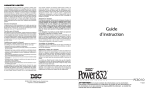
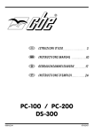
KONTROLLPANEEL “PC-540HY ”
2
6
1
8
Motor
3
4
7
5
Flair
PC-540HY
9
10
11
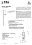
1)
Hauptschalter on/off: (Drücken ca. 2 Sekunden um einzuschalten).
Durch Drücken des Tasters kann man von dem “ON” Modus an das “STAND-BY” Modus umschalten.
Durch Drücken länger als 2 Sekunden geht das System aus.
- “ON” Modus: das ganze System und alle Verbraucher können funktionieren.(Beleuchtetes LED
zeigt an, daß der betroffene Verbraucher an ist).
- “STAND-BY” Modus: Heizung, EIS-EX, Gasventil und Gas Sensor können funktionieren.
Bei diesem “STAND-BY” Modus alle Verbraucherschalter werden ausgeschaltet mit der
Ausnahme von denen betreffend die Heizung, die wie bei “ON” Modus bleiben.
Die Led’s von den Verbraucherschaltern gehen aus und am LCD-Display erscheint ein
entsprechendes Symbol. (Alle Alarme werden auch ausgeschaltet mit der Ausnahme von dem
Gas Sensor und von der Gas-Reserve).
2) Taster für die “Volt” Überwachung von der Spannung der Fahrzeug- u. Verbraucherbatterie;
überwacht auch die Entlade- u. Ladestrom in Ampere von der Verbraucherbatterie (sieh auch
Funktionen “AMPEREMETER”.
3) Taster für die Überwachung in “%” der FW- AW- u. Fäkalientanks; dient auch der Funktion “FW-Tank
Einfüllung” (sieh auch Funktion "FW-Tank Einfüllung".
4) PROG Taster für die Programmierung von dem System (sieh Programmierung).
5) Taster für die Einstellung der zu programmierenden Parametern (sieh Programmierung).
6) Taster für die Ein- u. Ausschaltung der Pumpe (sieh Funktion Pumpen-Sperr).
7) Taster für das Motorwärmetauscher.
8) Taster für die Eisschutz-Widerstand “EIS-EX”.
9) Taster für das Gasventil; die Umschaltung “Start/ Mindestverbrauch” wird automatisch vom
Mikroprozessor gesteuert. Im Fall vom Gas-Überfall wird das Gasventil automatisch zugemacht.
10) Taster für die Alarmsensoren; diese Funktion bleibt unverändert auch bei System aus.
11) Taster für das Gas Sensor; geht nicht bei zugemachten Gasventil.
WICHTIG: - Während einer Test-Funktion (Batterie ref. 02 und Tanks ref. 03) ist es möglich die Meldung
am Display für eine Minute “festzuhalten”, wenn Sieden Taster “PROG” ref. 04 drücken
- Um eine Alarm-Meldung zu entlassen, drücken Sie einen von den 2 Pfeile-Tastern 56 ref. 05.
4
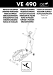
ANZEIGE KONTROLLPANEEL “PC-540HY ”
“ON” Modus
5
1
3
2
“STAND-BY” Modus
6
7
4
8
G
10
23
24
23:56
25,02,02
DEUTSCH
25
STAND BY.
9
22
10
R
11
18
R
12
1)
2)
3)
4)
5)
6)
7)
8)
9)
10)
11)
12)
13)
14)
15)
16)
17)
18)
19)
20)
21)
22)
23)
24)
25)
13
14
15
16
19
16
20
17
21
17
Zeigt Aufladung mittels Solarpanel (nur mir CBE Solarladeregler) an.
Zeigt 230V Netz an. (Symbol erscheint auch bei ausgeschaltetem Panel, wenn 230V Nezt
anliegt).
Zeigt Batterie-Parallel an bei angestartetem Motor oder Fzg-Batterie Mitladungseinrichtung an
(Symbol erscheint auch bei ausgeschaltetem Panel, wenn Batterie-Paraller oder Fzg-Batterie
Mitladungseinrichtung an sind).
Zeigt die Aufladung der Fahrzeug- u. Verbraucherbatterie mittels Lichtmaschine an (Symbol
erscheint auch bei ausgeschaltetem Panel und Zündung an).
Zeigt Verbraucherbatterie Alarm an.
Zeigt Fahrzeugbatterie Alarm an.
Zeigt das Batterie-Alarm zusammen mit den Symbolen ref. 5 oder 6 an.
Zeigt an, daß die Tiefentladungsschutz aktiviert wurde.
Wecker an.
Digitale Uhr.
Digitale Datumsangabe.
Bei Motor an, zeigt an, daß die Trittstufe ausgefahren ist.
Zeigt an, daß die Pumpe gesperrt wurde.
Wenn blinkend, ist FW-Tank leer.
Wenn blinkend, ist AW-Tank voll oder ist Fäkalien-Tank voll.
Zeigt an, daß die Gasflasche fast leer ist.
Zeigt eventuelle Gasüberfälle an.
Zeigt an, daß das Gasventil auf ist.
Zeigt an, daß die Heizung an ist.
Zeigt an, daß das “EIS-EX” an ist.
Zeigt an, daß das Gas Sensor aktiv ist.
Zeigt das “STAND-BY” Modus an.
Zeigt an, dass die alarmanlage aktiv ist (sonderausstattung).
Zeigt an, dass die modalität “sms schicken” aktiv ist (sonderausstattung).
Zeigt die stärke des empfangsfelds an (sonderausstattung).
5
FUNKTIONEN
230V ANGESCHLOSSENES NETZ ALARM
Wenn bei Zündung an ist das 230V Aussennetz angeschlossen, wird das Alarm aktiviert.
Das Alarm wird akustisch und mit der Meldung “230V ANGESCHL.” angezeigt. Die Symbole ref. 02 und 04
blinken auch. Auch bei ausgeschaltetem Panel, ist das Alarm aktiv.
FAHRZEUG BATTERIE ALARM (B1)
Wenn die Fahrzeug-Batterie eine Spannung < als 12V erreicht, geht das Alarm “FZG-BATT.ENTL.”
automatisch an und blinken die Symbole ref. 06 und 07.
FAHRZEUG BATTERIE MITLADUNG (B1)
Mittels Ladegerät oder Solarpanel: eine elektronische Einrichtung (die vom Mikroprozessor gesteuert wird)
erlaubt eine Mitladung (maximal 4A) von der Fahrzeug-Batterie, erst wenn die Fahrzeug-Batterie eine
Spannung < als 12,5V hat und die Verbraucherbatterie eine Spannung > als 13,6V hat; System gibt aber
Priorität der Verbraucherbatterie (B2).
Diese Funktion wird von dem Symbol ref. 03 am Display angezeigt.
Dieses System ist bei Verbraucherbatterie-Spannung (B2) < 13V nicht mehr aktiv.
Mittels Solarpanel wird diese Einrichtung erst mit angeschaltetem Control Panel angezeigt; bei 230V
angeschlossenem Netz wird diese Funktion automatisch angemacht.
VERBRAUCHER BATTERIE ALARM (B2)
Wenn die Verbraucher-Batterie eine Spannung von 11V erreicht, geht das Alarm “VERBR-BATT.RES.”
automatisch an und blinken die Symbole ref. 05 und 07.
Wenn die Verbraucher-Batterie eine Spannung von 10,5V erreicht, geht das Alarm “VERBR.BATT.ENTL.”
an.
VERBRAUCHER BATTERIE AUFLADUNG (B2)
a) mittels Lichtmaschine: dank dem Trenn-Relais wenn das Motor an ist. Die Zundüng steuert elektronisch
die ganzen Relais:Parallel, Kühlschrank, Vorzeltleuchte u.s.w....
b) bei 230V angeschlossenem Netz: Pufferbetrieb mittels Lagegerät (sieh "Ladegerät”).
c) mittels Solarpanel: durch Solarladeregler.
TIEFENTLADUNGSSCHUTZ (SAVE BATTERY)
Eine elektronische Einrichtung für den Batterieschutz schaltet alle 12V Verbraucher (in 3 Phasen) aus,
wenn die Batterie leer wird.
- Die erste Phase erfolgt bei 10V und werden folgende Verbraucher ausgeschaltet: indirekte
Beleuchtung re. u. li., Wasserpumpe, Lichtergruppe, Radio, Vorzeltleuchte, geschaltetes
Deckenleuchte, Motor-Heizung, Aux-Ausgang und 12V Steckdosen.
- Die zweite Phase erfolgt bei 9,8V und werden folgende Verbraucher ausgeschaltet: Heizung,
EIS-EX, Gasventil, Gas Sensor, Kontrollpaneel.
- Die dritte Phase erfolgt bei 9,5V und werden folgende Verbraucher ausgeschaltet: Versorgung der
Gas elektrischer Piezo und Versorgung von dem Eisschutz-Ventil vom Boiler.
Durch das Drücken von dem Taster “ON/OFF” (ref. 01 Kontrollpaneel) ist es möglich die 12V Verbraucher
wiedereinzuschalten oder können auch die Verbraucher einzeln durch das Drücken von dem
entsprechenden Schalter wiedereingeschaltet werden.
Die Verbraucher werden auch automatisch bei einer Spannung höher als 12,5V wiedereingeschaltet.
Von dieser Einrichtung sind die Funktionen Kühlschrank, Trittstufe und die AUX-Ausgang RES
ausgeschlossen.
TANKS
a) Frischwasser-Tank mit elektronischer Tankssonde: die Anzeige erfolgt in “%” dank der Numerischen
Anzeige und graphisch mit der “Einfüllung” des ausgewähltem Tank.
b) Abwasser-Tank mit elektronischer Tankssonde: die Anzeige erfolgt in “%” dank der Numerischen
Anzeige und graphisch mit der “Einfüllung” des ausgewähltem Tank.
c) Fäkalien-Tank mit 3-Stäbensonde: die Anzeige erfolgt in “%” dank der Numerischen Anzeige und
graphisch mit der “Einfüllung” des ausgewähltem Tank.
6
FRISCHWASSER-TANK EINFÜLLUNG
Man benutzt diese Funktion während der Frischwasser-Einfüllung und zeigt an, was für einen
Tankstand das Wasser erreicht hat.
Um diese Funktion zu aktivieren, soll man die Taster ( bez. 5) drücken, dann MODE-Taster für
mindestens 3 Sekunden drücken, dann wird die Meldung “FÜLLUNG” erscheinen.
Bei dieser angeschalteten Funktion man hat, in Folge, die Beleuchtung der Strichen der Ziffer ref. 8
und das Panel klingelt, um zu warnen, daß der Tank fast voll ist:
ein kurzer Klang bei 75%, zwei kurze Klänge bei 85% und ein langer Klang bei 95%.
Um diese Funktion zu verlassen, drücken Sie einen von den 2 Pfeile-Tastern 56 ref. 05.
FRISCHWASSER-TANK ALARM
Alarm geht bei Wasserstand < 10% an und geht automatisch aus, wenn das Wasserstand > 20% ist.
Alarm wird akustisch (nur bei Motor aus) und mit dem blinkenden Symbol ref. 14 gemeldet und
erscheint am Display “FW RESERVE”. In der Test-Funktion blinkt auch den Prozensatz-Wert.
ABWASSER-TANK ALARM
Alarm geht bei Wasserstand > 90% an und geht automatisch aus, wenn das Wasserstand < 80% ist.
Alarm wird akustisch (nur bei Motor aus) und mit dem blinkenden Symbol ref. 15 gemeldet und
erscheint am Display “AW VOLL”. In der Test-Funktion blinkt auch den Prozensatz-Wert.
FÄKALIEN-TANK ALARM
Alarm geht bei Fäkalienstand > 70% an und geht automatisch aus, wenn das Fäkalienstand 30% ist.
Alarm wird akustisch (nur bei Motor aus) und mit dem blinkenden Symbol ref. 15 gemeldet und
erscheint am Display “FÄK VOLL”. In der Test-Funktion blinkt auch den Prozensatz-Wert.
NB: Anzeige erfolgt erst in Schritten von: 0% - 30% - 70% - 100%
TRITTSTUFE ALARM
Alarm geht bei ausgefahrener Triitstufe und angestartetem Motor an.
Alarm wird akustisch gemeldet und erscheint am Display “TRITTSTUFE AUS”.Symbol ref. 12 blinkt
auch.
PUMPE SPERR
Eine elektronische Einrichtung sperrt automatisch die Wasserpumpe nach einer vorgewählten
Betriebszeit.
Es gibt kein akustisches Alarm; am Display erscheint aber “PUMPE SPERR”.
EISSCHUTZ VENTIL
Diese Ausgang wurde spezifisch für das Eisschutz-Ventil vom Boiler und Gas elektrischer Piezo
entwickelt und ist sie immer aktiv. Die ist von einer unabhängigem Tiefentaldungsschutz bei 9,5V
gesteuert; Ausgang kann aber durch das Drücken von dem “ON/OFF” Taster vom Kontrollpaneel für
eine Minute neueingeschaltet werden.
AMPEREMETER
Amperemeter ist in Verteilermodul DS-340HY enthalten.
- Mißt den Strom von Verbraucherbatterie.
- Die Werte gehen von - 50A bis + 50A mit Messgenauigkeit von 0,1A.
- Die Messung erfolgt als Differenz von Lade u.Entladeströme. Der “eintretende” Pfeil mit dem
Symbol + zeigt “Aufladungstrom” an und der “austretende” Pfeil mit dem Symbol - zeigt Entladestrom an.
Wenn Sie die Aufladung von einer einzigen Ladequelle (Ladegerät, Lichtmaschine oder
Solarpanel) messen wollen, schalten Sie alle Verbraucher und die restlichen Ladequellen aus.
Wenn Sie den Verbrauch von einem einzigen Verbraucher messen wollen, schalten Sie alle
Ladequellen und die restlichen Verbraucher aus.
VORSICHT:
- Bevor den Amperemeter einzustellen, alle Verbraucher und Ladequellen ausschalten.
- Der am Dispaly angezeigte Amperewert berechnet den Selbstverbrauch von dem
elektronischen System nicht.
7
DEUTSCH
FUNKTIONEN
FUNKTIONEN
ELEKTRONISCHES BATTERIETRENNGERÄT
Eine elektronische Einrichtung, die von Zündung gesteuert wird, schaltet den Batterieparallelbetrieb
bei Fahrzeugbatterie-Spannung > 13,5V an, und schaltet den Batterieparallelbetrieb bei Zündung aus
oder bei Spannung < 12,5V aus.
Außerdem bedient diese elektronische Einrichtung die Verbraucherrelais von Ausgang OUT D+
(simuliertes D+) abhängig (AES-Kühlschrank, Vorzeltleuchte, Antenne-Einfahrt, us.w...).
SOS LICHTER SICHERUNG
Im Falle von Mißarbeitsweise der 12V Anlage kann man die 3A Sicherung in den entsprechenden
Sitz (ref. 03 vom Relaisbox DS-540HY) einsetzen, um die Versorgung von Lichtern, Heizung, und
Gasventil wiedereinzuschalten (in diesem Fall sind diese Verbraucher ausser der Kontrolle von
Mikroprozessor).
VORSICHT: nur im Notfall und für kurze Zeit benutzen!
VORSICHTl: mit dieser eingesetzten Sicherung geht der Tiefentladungsschutz nicht; eine zu
starke Entladung könnte die Batterie endgültig beschädigen!
NOT-BATTERIEPARALLEL SICHERUNG
Im Falle von Mißarbeitsweise von dem Batterie-Trenngerät kann man die 3A Sicherung in den
entsprechenden Sitz (ref. 02 vom Relaisbox DS-540HY) einsetzen, erst mit Motor aus; so wird das
Batterieparallel wiedereingeschaltet,aber ausser der Kontrolle von Mikroprozessor. Bei
angeschaltetem Panel wird diese Funktion durch die Meldung “SOS-LICHTER AN” angezeigt.
.
VORSICHT: nur im Notfall und bei angestartetem Motor benutzen.
VORSICHT: ERST BEI MOTOR AUS DIESE SICHERUNG EINSETZEN, SONST KÖNNEN DIE
KABELSTRÄNGE BESCHÄDIGT WERDEN!
AUTOMATISCHE AUSSCHALTUNG DES VORZELTLEUCHTES
Eine elektronische Einrichtung schaltet das Vorzeltleuchte bei angestartetem Motor automatisch aus
(wenn Sie Motor ausmachen, geht das Vorzeltleuchte wieder an).
DIGITALE UHR u. DATUM
Für die Einstellung der Uhr und des Datums, sieh “Programmierung”.
WECKER
Für die Wecker-Einstellung, sieh “Programmierung”.
Um das Wecker-Alarm auszuschalten, drücken Sie einen Test-Taster; es gibt keine weitere Alarme!
GAS-RESERVE ALARM
Alarm geht an, wenn die Hauptflasche leer ist.
Alarm wird durch die Meldung “GASFLASCHE” angezeigt und blinkt auch das Symbol ref. 16.
GAS ALARM
Alarm geht bei Gas-Überfallen an und geht das Gasventil automatisch zu.
Alarm wird akustisch und durch die Meldung “GAS ALARM” gemeldet . Symbol ref. 17 blinkt auch.
8
ALARMANLAGE-FUNKTIONEN (OPTIONAL)
ALARM AUFGEBROCHENE TÜREN ODER KLAPPEN
Der Alarm zeigt das Aufbrechen einer Tür oder einer Klappe mit eingeschalteter Alarmanlage an.
Der Alarm wird optisch mit wiederholtem Blinken der Blinker 25 Sekunden lang, akustisch mit einem
ununterbrochenen Ton des Summers und einem aussetzenden der Hupen 25 Sekunden lang
angezeigt.
Der Alarm wird auch von den folgenden Nachrichten angezeigt:
- « ALM KLP LI » mit linker Klappe offen
- « ALM KLP RE/HECK » mit rechter und/oder hinterer Klappe offen
- « ALM AUFBAUTÜR » mit Aufbautür offen
- « INNENRAUMÜBERW. » mit Alarm Innenraumüberwachung-Sensoren.
DEUTSCH
ÖFFNEN MIT SCHLÜSSEL
Mit ausgeschalteter Alarmanlage, indem ein Schloss von Hand mit dem Schlüssel gesperrt/entsperrt
wird, sperren/entsperren sich automatisch die anderen Schlösser derselben Gruppe (Klappegruppe
links, Klappegruppe rechts/hinten, Aufbautür und Fahrertür). Diese Funktion wird bei eingeschalteter
Alarmanlage deaktiviert.
INNENRAUMÜBERWACHUNG
Der Alarm zeigt das Vorhandensein von Bewegungen innerhalb des Fahrzeugs an und wird optisch
mit der Aufschrift « INNENRAUMÜBERW. » und wiederholtem Blinken der Blinker 25 Sekunden lang,
akustisch mit einem ununterbrochenen Ton des Summers und einem aussetzenden der Hupen 25
Sekunden lang angezeigt.
PANIK-ALARM (OPTIONAL)
Der Alarm tritt bei Drücken der Drucktaste PANIK, die sich innen im Wohnmobil befindet, auf. Der
Alarm wird optisch mit wiederholtem Blinken der Blinker 25 Sekunden lang, akustisch mit einem
ununterbrochenen Ton des Summers und einem aussetzenden der Hupen 25 Sekunden lang
angezeigt.
Die PANIK-Funktion ist auch mit ausgeschalteter Alarmanlage aktivierbar.
ALARM VERBRAUCHERBATTERIE « B2 » (mit aktivierter Alarmanlage)
Der Alarm tritt auf, wenn die Verbraucherbatterie « B2 » eine Spannung von weniger als 10V hat oder
unterbrochen wird. Der Alarm wird optisch mit wiederholtem Blinken der Blinker 25 Sekunden lang,
akustisch mit einem ununterbrochenen Ton des Summers und einem aussetzenden der Hupen 25
Sekunden lang angezeigt.
GSM (OPTIONAL)
Diese Vorrichtung ermöglicht das Senden einer SMS-Nachricht an ein oder zwei Handys der
folgenden bei eingeschalteter Alarmanlage erfolgten Alarme:
- « ALM KLP LI » mit aufgebrochener linker Klappe
- « ALM KLP RE/HECK » mit aufgebrochener rechter und/oder hinterer Klappe
- « ALM AUFBAUTÜR » mit aufgebrochener Aufbautür und /oder Fahrertür.
- « INNENRAUMÜBERW. » mit Eingriff Alarm Innenraumüberwachung
- « ENTL.VERBR-BATT. » mit Spannung Verbraucherbatterie « B2 » unter 10V
- « ABGEKLEMMTE VERBR-BATT » mit fehlender Spannung bei Verbraucherbatterie «B2»
9
ALARMANLAGE-FUNKTIONEN (OPTIONAL)
EINGABE TELEFONNUMMER (OPTIONAL)
Nach Zugang zur « KUNDENPROGRAMMIERUNG » auf dem Kontrollpaneel « PC-540HY » im
Menü KONF. ALARMANLAGE/ TELEFON-NR mit den Drucktasten Bez. 5 jede Ziffer eingeben und
sie mit der Drucktaste PROG. Bez. 4 bestätigen.
VORZELTLEUCHTE ZEITGESTEUERT
Eine elektronische Vorrichtung erlaubt das zeitgesteuerte Einschalten des Vorzeltleuchtes mit der
Drucktaste Bez. 5 der Fernbedienung; das Licht bleibt für den auf des Kontrollpaneels PC-540HY
(siehe KUNDENPROGRAMMIERUNG) eingegebenen Zeitraum an.
STÖRUNG TÜREN ODER KLAPPEN OFFEN
Die Störung wird bei offenen Türen oder Klappen und mit steckendem Fahrzeugzündschlüssel
(+Schlüssel) angezeigt.
Die Störungsnachrichten sind:
- « KLP LI. AUF » mit linker Klappe offen
- « KLP RE/HECK AUF » mit rechter und/oder hinterer Klappe offen
- « AUFBAUTÜR AUF » mit offener Aufbautür und /oder Fahrertür.
KONTROLLE STÖRUNGEN
Bei der Aktivierung führt die Alarmanlage eine Kontrolle eventueller Störungen der
Verschlussvorrichtungen und der Innenraumüberwachung-Sensoren durch. Diese Störungen werden
mit 5 Mal einem kurzen Blinken der Blinker angezeigt.
AKTIVIERUNG FERNBEDIENUNG
Nach Zugang zur « HERSTELLER-PROGRAMMIERUNG » auf dem Kontrollpaneel « PC-540HY »
im Menü KONF. ALM-ANLAGE N+B/ FERNBEDIENUNG/ INBETRIEBSETZUNG « ON » wählen.
Kurz drei Mal hintereinander die Drucktaste 2 der Fernbedienung drücken. Das dritte Drücken dient
zur Überprüfung mittels des Blinkens der Blinker, dass die Fernbedienung erfasst wurde.
RESET FERNBEDIENUNG
Erlaubt die Deaktivierung aller Fernbedienungen (siehe HERSTELLER-PROGRAMMIERUNG).
Nachdem einmal die Rückstellung durchgeführt wurde, müssen die Fernbedienungen reaktiviert
werden (siehe AKTIVIERUNG FERNBEDIENUNG).
ZU BEMERKEN: Wie von den Richtlinien vorgesehen, wird der Alarm der Alarmanalge maximal 10
Mal ausgelöst; die Deaktivierung der alarmanlage stellt die Zählung der Eingriffe null.
10
STAND BY
“STAND-BY” Modus.
VORSICHT !
SYSTEM AUS
Panel und alle Verbraucher gehen aus, mit der Ausnahme von der
Eisschutz-Ventil vom Boiler.
EIS-EX AN
EIS-EX AUS
Bestätigt die Einschaltung von EIS-EX bei “ON” Modus.
Bestätigt die Ausschaltung von EIS-EX bei “ON” Modus.
GAS SENSOR
NICHT NOTWE
Zeigt an, daß Gas Alarm nicht notwendig ist, da das Gasventil zugemacht ist
GASVENTIL AUF
GASVENTIL ZU
WASSERPUMPE AN
WASSERPUMPE AUS
Bestätigt die Aufmachung vom Gasventil bei “ON” Modus.
Bestätigt die Zumachung vom Gasventil bei “ON” Modus.
WÄRMETAUSCHER
PUMPE AN
Bestätigt die Einschaltung von Wärmetauscher bei “ON” Modus.
WÄRMETAUSCHER
PUMPE AUS
Bestätigt die Ausschaltung von Wärmetauscher bei “ON” Modus.
RAUM
ÜBERWACHUNG AN
Bestätigt, daß die Innenraum-Sensoren vom Alarmsystem nicht aktiviert
sind (bei “ON” Modus).
RAUM
ÜBERWACHUNG AUS
Bestätigt, daß die Innenraum-Sensoren vom Alarmsystem aktiviert sind
(bei “ON” Modus).
Vorsicht: die Innenraum-Sensoren funktionieren erst wenn das
Alarmsystem eingeschaltet sind, egal ob die aktiviert sind.
GAS SENSOR AN
Bestätigt die Einschaltung von Gas Sensor bei “ON” Modus
GAS SENSOR AUS
Bestätigt die Ausschaltung von Gas Sensor bei “ON” Modus
Bestätigt die Einschaltung von Wasserpumpe bei “ON” Modus.
Bestätigt die Ausschaltung von Wasserpumpe bei “ON” Modus.
Fahrzeug-Batterie Test.
Verbraucher-Batterie Test.
Frischwasser-Tank Test
Abwasser-Tank Test
Fäkalien-Tank Test
FÄK
GASFLASCHE RESERVE Haupt-Gasflasche fast leer
Alarm Gas in Innenraum.
GAS ALARM
Zeigt an, daß die Pumpe gesperrt wurde.
PUMPE SPERR
Bei Motor an, zeigt an, daß die Trittstufe ausgefahren ist.
TRITTSTUFE AUS
VERBR-BATT. RESERVE Zeigt an, daß die Verbraucher-Batterie in Reserve ist.
VERBR-BATT. ENTLADE Zeigt an, daß die Verbraucher-Batterie entladen ist.
Zeigt an, daß die Fahrzeug-Batterie in Reserve ist.
FZG-BATT. ENTLADE
FRISCHWASSER RESERVE Zeigt an, daß die Fahrzeug-Batterie entladen ist.
Zeigt an, daß Abwasser-Tank voll ist.
ABWASSER VOLL
Zeigt an, daß Fäkalien-Tank voll ist.
FÄKALIEN VOLL
Zeigt an, daß Wc-Tank voll ist.
WC VOLL
Zeigt an, daß die Sicherung “SOS-Lichter” aktiviert wurde.
SOS LICHTER AN
FZG
VERBR
FW
AW
11
DEUTSCH
MELDUNGEN AM DISPLAY
BATTERIESCHUTZ
- MENÜ 230V ANGESCHL.
SONDERAUSTATT.
FW-EINFÜLLUNG
SITZVERRIEGELUNG.
KLP LI. AUF
KLP RE/HECK AUF
AUFBAUTÜR AUF
ALM KLP LI
ALM KLP RE/HECK
ALM AUFBAUTÜR
INNENRAUMÜBERW.
Zeigt an, daß die Tiefentladungsschutz-Einrichtung aktiviert wurde.
Zurück zum Hauptmenü.
.Bei Zündung an, zeigt das 230V angeschlossenes Netz an.
Zeigt an, daß die ausgewählte Funktion nicht vorhanden ist.
Zeigt an, daß die “FW-Tank Einfüllungsfunktion an ist.
Zeigt an, dass die Sitzkonsole nicht in der richtigen Stellung ist.
Zeigt an, dass die linke klappe mit laufendem Motor offen ist.
Zeigt an, dass die rechte und/oder hintere klappe mit laufendem
Motor offen ist.
Zeigt an, dass die Zellen- und/oder Fahrertür mit laufendem Motor offen ist.
Alm klappe links aufgebrochen.
Alm klappe recht und/oder hinten aufgebrochen.
Alm Zellen- und/oder Fahrertür aufgebrochen.
Alm raum überwachung mit alarmanlage eingegriffen.
KUNDENPROGRAMMIERUNG
s
s
s
s
s
s
s
Um programmieren zu können, muß das Panel eingeschaltet und auf “ON” Modus sein.
Drücken den Taster “PROG” ref. 04 mehr als 2 Sekunden um in das Programmierungsmenü zu
wechseln.
Um die Menü-Parameter zu sehen, drücken Sie die Pfeile-Taster ref. 05.
Um die gewünschte Funktion auszuwählen, drücken Sie den “PROG” Taster.
Um die eingestellten Parameter zu retten, drücken Sie den “PROG”-Taster ref. 04; Um
abzubrechen warten Sie 10 Sekunden ohne Taster zu drücken und verlässt man das Menü
automatisch.
Um in das vorherige Menü zu wechseln, wählen Sie “áMENÜá” aus.
Um das Hauptmenü zu verlassen, wählen Sie “AUSGANG” (Ausgang wird durch die Meldung
“PROG. OK !” ).
WECKER
MENÜ à WECKER
à Funktion auswählen
-WECKER EINSTELLUNG
Einstellung des Weckers (STUNDEN / MINUTEN).
-ALARM
Wecker Alarm ein / aus (ON / OFF).
UHR
MENÜ à UHR
à Funktion auswählen
-UHR EINSTELLUNG
Einstellung der Uhr (STUNDEN / MINUTEN).
-DATUM EINSTELLUNG
Einstellung des Datums (TAG / MONAT / JAHR).
12
SPRACHE
MENÜ à SPRACHE
à Funktion auswählen
DISPLAY
MENÜ à DISPLAY
à Funktion auswählen
-KONTRAST
Einstellung des Display-Kontrasts (0÷100 %).
-HINTERGRUND
Einstellung der Hintergrund-Art (WEISS /SCHWARZ).
-BELEUCHTUNG
Die Displaybeleuchtung kann sein:
-AN (immer an)
-AUS (immer aus)
-AUTO (geht nach 10 Sekunden aus, wenn keine Taster gedrückt werden;
immer an bei 230V angeschlossenem Netz..
TÖNE
MENÜ à TÖNE
à Funktion auswählen
-ALLE
Alle akustische Warnsignal sind an.
-NUR ALARM
Nur die akustische Warnsignal von den Alarmen sind an. Die Töne der Tastatur sind aus.
-KEINE
Alle akustische Warnsignale sind aus.
ALARMANLAGE (OPTIONAL)
MENÜ à KONF. ALARMANLAGE
à Funktion auswählen
- GSM-MODE
- IMMER EINGESCH.
- NUR LARM-VERSAND (geht nur im Alarmfall an)
- OFF (immer aus)
- TELEFON-NR 1
Eingabe erste Telefonnummer
- TELEFON-NR 2
Eingabe zweite Telefonnummer
- ZEITVORZELTLEUCHTE
Eingabe Dauer Einschaltzeit Außenlicht (MINUTEN)
13
DEUTSCH
-ITALIENISCH
-DEUTSCH
-FRANZÖSICH
-ENGLISCH
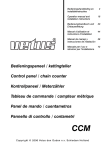
RELAISBOX “DS-540HY ”
3
3
5
15
7
20
14
5
28
6
20
3
2
1
6
5
4
8
3
24
29
5
M
3
7.5
20
15
20
17
2
1
6
5
4
9
8
7
20
20
19
22
3
10
21
5
27
32
1
26
13
RH
3
3
BAUTEILE-SEITE
10
25
RES
6
4
10
18
15
5
3
16
15
4
23
12
2
SOS
2
11
30
1
SOS
3
9
7.5
2
1
EINGANG B2
30
31
33
25
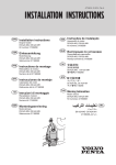
1)
3A Sicherung für den Schutz der Ausgang “simuliertes D+”.
2)
3A Sicherung für die Not-Aktivierung des Parallel-Systems.
3)
3A Sicherung für die Not-Aktivierung der Ausgänge Lichter, Heizung, Gasventil EIS-EX.
4)
15A Sicherung für die Versorgung der indirekten Beleuchtungen links und rechts.
5)
10A Sicherung für die Versorgung der Wasserpumpe; vom Wasserpumpeschalter abhängig.
6)
20A Sicherung für die Versorgung der Lichtergruppe “1”; funktioniert nur bei “ON” Modus.
7)
20A Sicherung für die Versorgung der Lichtergruppe “2”; funktioniert nur bei “ON” Modus.
8)
7,5A Sicherung für die Versorgung der Radio; vom Hauptschalter abhängig.
9)
3A Sicherung für die Versorgung des KontrollPaneel.
10) 30A Sicherung für die Versorgung des 12V AES u. Absorberkühlschrankes. Bei Motor aus geht der
Absorberkühlschrank automatisch aus.
11)
25A Sicherung für die Versorgung der elektrischen Trittstufe, direkt an Verbraucherbatterie (B2)
angeschlossen.
14
12) 5A Sicherung für die Versorgung des Vorzeltleuchtes; vom Lichterschalter abhängig; bei Motor aus
geht das Vorzeltleuchte automatisch aus.
13) 5A Sicherung für die Versorgung der geschalteten Deckenleuchte; vom Hauptschalter abhängig.
14) 7.5A Sicherung für die Versorgung des Motorwärmetauschers; funktioniert nur bei “ON” Modus.
15) 15A Sicherung für die Versorgung der Aux-Ausgang “RES”; direkt an Verbraucherbatterie (B2)
angeschlossen.
16) 20A Sicherung für die Versorgung der Lichtergruppe “3”; funktioniert nur bei “ON” Modus.
18) 20A Sicherung für die Versorgung der 12V Steckdosen; funktioniert nur bei “ON” Modus.
19) 20A Sicherung für die Versorgung der Alarm-Anlage; vom Alarm-Schalter abhängig und kann er nur
bei “ON” Modus ein- oder ausgeschaltet werden.
20) 10A Sicherung für die Versorgung der Heizung “Truma C”; funktioniert beide bei “ON” und “Stand-By”
Modus.
21) 3A Sicherung für die Versorgung vom Gas elektrischen Piezo (Kühlschrank, Küche u.s.w.) und vom
Eisschutzventil vom Boiler direkt an Verbraucherbatterie (B2) angeschlossen; immer an, sieh auch
Funktion “Eisschutz-Ventil”.
22) 5A Sicherung für die Versorgung von dem “EIS-EX” und dem Gasventil, funktioniert beide bei “ON”
und “Stand-By” Modus.
23) Kontroll-Platine (VORSICHT BEI MONTAGE!).
24) Das ist eine Brücke, die das Absorberkühlschrank-Relais ausschließt; sie dient, um den AES
Kühlschrank direkt an B2 anzuschließen.
ANSCHLUSS
25
33 SCHWARZ
12V EINGANG
ZUSATZ-PLATINE DS-340HY
Anschluss an DS-340HY ref. 29 .
12V EINGANG
26 SCHWARZ
Anschluss an Zusatz-Platine
DS-340HY.
KONTOLLPANEEL
Anschluss an Kontrollpaneel
PC-540HY.
27
28
29
30
31
32
WEISS
WEISS
SCHWARZ
SCHWARZ
WEISS
WEISS
6 5 4 3 2 1
12 11 10 9 8 7
18 17 16 15 14 13
4 3 2 1
8 7 6 5
12 11 10 9
ANSCHLUSS AN DS-340HY
15
DEUTSCH
17) 15A Sicherung für die Versorgung der Aux-Ausgang “RH”; funktioniert nur bei “ON” Modus.
12V VERTEILERMODUL “DS-340HY ”
2
1
3
2
1
3
2
1
6
5
4
6
5
4
6
5
9
8
7
9
8
9
8
7
12
11 10
26
3
6
9
12
22
5
6
20
14
1
13
2
3
2
1
11
16
26
24
11
23
31
15
17
25
12
2
19
1
U S C I TA 1 2 V
27
MASSE
Direkt an Minuspol von
Verbraucherbatterie (B2) oder am
Chassis zu verbinden
27
VERBRAUCHERBATTERIE
28
29
AUSGANG 12V
HECKMODUL
AUSGANG 12V
FAHRZEUGBATTERIE
An Minuspol von der Fahrzeugbatterie
zu verbinden.
33
WEISS
DOGLIGHT
1)
2)
Anschluss an Heckmodul.
30
Für den Anschluss von dem DS540HY, dem Ladegerät und eventuell
dem Solarladeregler.
An Pluspol von Verbraucherbatterie
(B2) zu verbinden.
32 SCHWARZ
8
18
28
25
5
3
4
3
1
2
7
6
4
2
4
5
5
5
10
4
6
1
7
3
1
2
33
1
32
2
2
4
10
8
3
4
1
1
9
34
2
2
3
2
4
7
1
6
1
2
3
4
21
5
1
3
4
3
34 SCHWARZ
16
+ Doglight
Masse
ARMATURENBRETT-KOMBIMODUL
Anschluss an ArmaturenbrettKombimodul und DS-540HY
ANSCHLÜSSE
WEISS
12
LI. SEITE
13
1) + Lichtergruppe 3
2-3) + Lichtergruppe 1
4) + Alarm (direkt B2)
5-8) + 12V Steckdosen
6) + Vorzeltleuchte
7) + gesch.Deckenl. Heck
9) + ind. Beleuchtung re.
3
WEISS
14
15
1 2
1) + Netzsignal
2) nicht belegt
ROT
SIGNAL
1 2
1) nicht belegt
2) Zündung
WEISS
6
16
WASSERPUMPE
ROT
SIGNAL
OPTIONAL
BODEN
1-2) + aux direkt
3) + Heizung
4) + Boiler Eisventil
5-6-10-11-12) + aux RH
7-8) + Lichtergruppe 3
9) + Radio Subwooofer
4
WEISS
RE. SEITE
ROT
5
4
3
2
1
WEISS
1 2 3 4 5 6
1) + Wasserpumpe
2) Masse
5
WEISS
MOTORHEIZUNG
17
1) + Motorheizung
2) Masse
6
WEISS
4
7
2
1
ROT
4
8
3
3
2
TRITTSTUFE
WEISS
1 2 3 4 5
1) Masse
2) - Trittstufenkontakt
3) Versorgung Trittst.-Motor
4) Versorgung Trittst.-Motor
18
ROT
SCHWARZ
1) nicht belegt
2) + Signal Solar
3-4) Raum Überwachung Sensoren aktiv
5-6) + segnale out D+
GESCH. SCHALTER
1) - Trittstufe ausfahren
2) - gesch.Deckenleuchte Heck
3) - Trittstufe einfahren
4) - ind. Beleuchtung re.
5) - ind. Beleuchtung li.
6) Masse
EIS-EX / GASVENTIL
1) Masse
2) +Start Gasventil
3) + Erhaltung Gasventil
4) + EIS-EX
5) - Signal Reserve EIS-EX
WC
1) Masse
2) + Wc
3) - Signal Wc Voll
4) nicht belegt
KÜHLSCHRANK
1
FÄKAL-TANKSSONDE
1) Masse
2) Stand 1/3
3) Stand 2/3
4) Stand 3/3
1) + ind. Beleuchtung li.
2) Lichtergruppe 3
3) + gesch.Deckenleuchte Heck
4-5) + Lichtergruppe 2
6) + 12V Steckdosen
2
SCHWARZ
1) Masse
2) + out D+
3) + Kühlschrank
4) + elektr. Piezo / Gas Kocher
19 SCHWARZ
ZUS.SCHALTERKONSOLE
MASSE ANSCHLUSS
1-3) Kontakt Trittstufe Einfahrt
2) Ausgefahrene Trittstufe-Warnleuchte
4) nicht belegt
9
10
11
BLAU
WEISS
SCHWARZ
20
GAS SENSOR
ROT
OPTIONAL
1) + Signal out D+
2) + Aux direkt B2
3) Masse
FW-TANKSSONDE
31
ROT
SITZKONSOLE
1-2) nicht belegt
3-4) Signal Sitzkonsole
AW-TANKSSONDE
21
22
23
24
25
26
WEISS
ROT
SCHWARZ
SCHWARZ
WEISS
WEISS
6 5 4 3 2 1
12 11 10 9 8 7
18 17 16 15 14 13
4 3 2 1
8 7 6 5
12 11 10 9
ANSCHLUSS AN DS-540HY
17
DEUTSCH
1
MASTER ALARMANLAGE (OPTIONAL)
4
11
12
13
1)
1
4 3
2 1
6 5 4
3 2 1
6 5 4
3 2 1
7
8
9
6
1 2 3 4
5
1 2 3 4
10
2
1
2
1
2
1
2
1
1
1
1
1
2
2
2
2
3
2
4
4
1
3
2A Absicherung für den Schutz der Versorgung «MASTER ALARMANLAGE » von der
Fahrzeugbatterie «B1»
2A Absicherung für den Schutz der Versorgung «MASTER ALARMANLAGE » von der
Verbraucherbatterie «B2»
2)
ANSCHLUSS
3
WEISS
4
4
5
3
2
WEISS
1
VERSORGUNG MASTER
8
WEISS
VORZELTLEUCHTE-RELAIS
1) Kontakt “normally closed”
2) Kontakt “gemein”
3) Masse
4) Kontakt “normally open”
5) Nicht belegt
6) + Versorgung direkt B2
9
ROT
TRITTSTUFE-RELAIS
1) Kontakt “normally closed”
2) Kontakt “gemein”
3) Masse
4) Kontakt “normally open”
5) Nicht belegt
6) + Versorgung direkt B2
1) - Masse
2) + Verbraucherbatterie B2
3) - Masse
4) + Verbraucherbatterie B1
VERSORGUNG BUS-MODULEN
1) - Masse
2) + Versorgung Bus-Modulen B2
WEISS
ANSCHLUSS BUS-MODUL
“ULTRASCHALLSENSOREN”
6
ROT
ANSCHLUSS “GAS-DETECTOR”
7
WEISS
EINGÄNGE
1) Kontakt AUX (alarm aktiv bei
Masse)
2-4) Kontakt Taster “PANIK”
3) + Zündung
10 SCHWARZ
KOMMUNIKATIONSLEITUNG
BUS-MODULEN ALARMANLAGE
11 SCHWARZ
ZUSATZ-PLATINE “DS340-HY”
Soll an die Zusatz-Platine vom
DS340-HY angeschlossen
12
13
GSM-MODUL
Soll an das GSM-Modul
angeschlossen werden
18
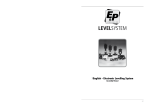
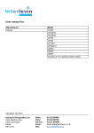
ELECTRONIC BATTERY CHARGER
ALARM
FUSE
C°
Gel
6h
14,4V
Mod. A 2018
13,8V
Input 180/250V
50/60 Hz
Output power 300VA
Max. charging current 18A
Charge temp. controlled
U
I
O
by
I
Pb
1h
Read the instructions before use
Retro
1
2
C°
IUoU characteristic
t a 40/E
Install in a cool and ventilated place
3
4
5
230 V
Made in Italy
6
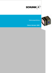
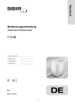
1)
LED Anzeige Sicherungen: es schaltet ein, wenn die Sicherung kaputt ist, nur wenn eine Belastung
an der Batterie angeschlossen ist.
2)
Stecker für die Verbindung der Temperaturfühler (OPTIONAL).
3)
Bedienungl für die Funktion mit oder ohne Temperaturfühler.
NB: Wenn der Temperaturfühler nicht angeschlossen ist, bitte auf die Position “0” stellen, ansonsten
funktioniert das Ladegerät nicht.
4)
Bedienung für die Wahl der angeschlossenen Batterie: “Pb” Bleibatterie, “Gel” Gel-Batterie.
5)
Rotes Led für die Anzeige der Ladungsphase (14,4V), grünes Led für die Anzeige der Erhaltungsphase (13,8V).
6)
Sicherheitschalter on/off.
FUNKTIONEN
Das Ladegerät Switching Serie A 2000, ist imstande Gel-Batterien (Verbraucherbatterie) oder
Bleibatterien (Starterbatterie) automatisch zu laden.
Die Technologie Switching erlaubt bei hoher Frequenz eine hohe Leistung mit geringerem Gewicht und
Dimensionen.
Die Ladung erfolgt in drei Fasen:
- Maximale Ladung: bei maximalem Strom, elektronisch begrenzt, bis zur Erreichung der 14,4V (25°C).
- Ende der Ladung: bei 14,4V (25°C) konstant für: 1h (Bleibatterie), 6h 20' (Gelbatterie).
- Erhaltung: bei 13,8V (25°C) konstant bis zur Einfügung einer Belastung.
19
DEUTSCH
ELEKTRONISCHES BATTERIELADEGERÄT “A2018”
TECHNISCHE DATEN
Versorgung
180 ÷ 250 Vac 50 ÷ 200 Hz
Maximale Stark
300 VA
Leistung
86%
Thermo-einstellbarer Ausgang (mit Außentemperaturfühlern)
13,5 ÷ 15,5 Vcc
Maximaler Ausgangsstrom
18A
Stromkontrolle
Verbrauch (Netz 230V nicht angeschlossen)
0,02 mA
Automatische Kontrolle der Ladespannung
- Maximale Ladung
- Ende Ladung
- Erhaltung
25°C (0 ÷ +50)
14,4V (15,6 13,6)
14,4V (15,6 13,6)
13,8V (15,0 13,0)
Art von Batterie
Bleibatterie - Gelbatterie
Ladungssystem
Pufferbetrieb
Schutz vor Überladung
Schutz vor zu hoher Temperatur
50 °C
Vor Verpolung geschützt
Sicherheitsschalter on/off
Schutz Sicherung 12V
PKW Art 25A
Schutz Sicherung 230V
Inneren 3,15A
Led-Anzeigen für die Ladephasen-Anzeige
Anzeige kaputte Sicherung
Temperaturfühler
Optional
Erzwungene Lüftung
Gehäuse aus eloxiertem Aluminium
Netzverbindung 230V
Schukostecker
Batterieverbindung
Kabelschuhe
Verbindung Netzsignal
Kabelschuh 6,3
Dimensionen (mm)
185 x 205 x 85
Gewicht
Standard
2 Kg
Ladekennlinie IUoU
VI
14,5V
13,8V
C
13,3V
V
A
I
20
V = Volt
Uo
A = Ampere
U
Uo
C = Carico - Load
t
ZUSATZ-PANELE
DUCATO 244 ZUSATZ-SCHALTERKONSOLE
1
1)
2)
3)
4)
5)
6)
7)
8)
9)
2
5
7
4
6
L
R
8
9
DEUTSCH
3
Taster für die Bedienung der Fahrerhausbeleuchtung.
Taster für die Bedienung der Nebelscheinwerfer.
Symbol wird beleuchtet, wenn die Nebelscheinwerfer an sind (grünes LED).
Taster für die Bedienung der Spiegel-Beheizung.
Symbol wird beleuchtet, wenn die Spiegel-Beheizung an ist (grünes LED).
Taster für die Trittstufe-Einfahrt.
Bei angestartetem Motor und bei ausgefahrener Trittstufe, blinkt das Symbol (rotes LED) und bibt es
auch ein akustisches Warnsignal.
Taster für die Bedienung des linken Sonnenblendenrollos.
Taster für die Bedienung des rechten Sonnenblendenrollos.
Bei angeschalteten Scheinwerfern erhalten alle Symbole eine Hinterbeleuchtung (orange).
ARMATURENBRETT-KOMBIMODUL
1
2
Panel für die Anzeige der Aussentemperatur (TEMP EXT) und der folgenden Alarmen:
- Gasflucht “GAS ALARM”.
- 230V Aussennetz liegt an “230V ANGESCHL.”.
- Ausgefahrene Trittstufe “TRITTSTUFE AUS”.
- Sitzkonsole nicht in der richtigen Stellung “SITZVERRIEGELUNG.”.
- Klappe links offen mit laufendem Motor “KLP LI. AUF” (OPTIONAL)
- Klappe rechts und/oder hinten offen mit laufendem Motor “KLP. RE/HECK AUF” (OPTIONAL)
- Zellen-und/oder Fahrertür offen mit laufendem Motor “AUFBAUTÜR AUF” (OPTIONAL)
Eine rote Warnleuchte rif. 2 warnt vor möglichen Eisglätten auf der Straße bei Aussentemperatur < 3°C.
Wenn ein von den 4 Alarmen auslöst, sendet das Panel ein Tripel-Beep. Durch das Drucken vom Taster
ref. 1 ist es möglich das angezeigte Alarm zu beseitigen.
Die Anzeige erfolgt erst bei angeschaltetem Motor.
21
HECKMODUL
1
2
3
1)
Doglight- Schalter, vom Hauptschalter abhängig.
2)
Taster für die Wecker-Einstellung; man kann beide Stunden und Minuten dadurch einstellen.
3)
Taster für die Einschaltung und die Ausschaltung des Weckers. Wird auch benutzt um die Ziffer von
Stunden und Minuten bei der Wecker-Einstellung zu vorwärtsgehen.
BETRIEB
Das Display zeigt die laufende Stunde, die Außentemperatur und die Alarme der alarmanlage und
des Gasdetektors an:
- "GAS ALARM”
- Klappe LINKS aufgebrochen “ALM KLP LI” (SONDERAUSSTATTUNG)
- Klappe RECHTS und/oder HINTEN aufgebrochen "ALM KLP RE/HECK"
(SONDERAUSSTATTUNG)
- Zellentür aufgebrochen “ALM AUFBAUTÜR” (SONDERAUSSTATTUNG)
- Alarm Volumensensoren mit alarmanlage eingegriffen “INNENRAUMÜBERW.“
(SONDERAUSSTATTUNG)
Wenn einer der Alarme aktiviert wird, wird die entsprechende Nachricht bis zur Beseitigung der
Alarmursache auf dem Display angezeigt.
Das Heckmodul funktioniert erst wann das Kontrollpaneel PC540-HY ist an oder in stand-by.
Die Uhr-Anzeige ist vom Kontrollpaneel PC540-HY gesteuert.
EINSTELLUNG UND BETRIEB DES WECKERS
Um das Wecker einzustellen den Taster ref. 2 fuer 2 Sek. drucken; am Display blinken dann die Ziffer
von den Stunden.
Durch das Drucken vom Taster ref. 3 kann man die Ziffer vorruecken.
Durch das Drucken vom Taster ref. 2 kann man die Ziffer der Minuten einstellen; am Display blinken
die Ziffer der Minuten.
Um die Wecker-Einstellung zu bestaetigen den Taster ref. 2 nochmals drucken..
Nach der Einstellung der Weckerzeit ist es notwendig das Wecker-Alarm zu aktivieren; das erfolgt
durch das Drucken vom Taster ref. 3 fuer 2 Sek.
Das Wecker-Alarm bleibt ständig an bis auf das durch den Taster ref. 3 ausgeschaltet wird.
Das Symbol % am Display zeigt an daß das Wecker-Alarm an ist.
Das Warnsignale vom Wecker-Alarm bleibt für 1 Minute an außer wenn Taster ref. 2 oder ref. 3
gedruckt werden.
22
FERNBEDIENUNG (OPTIONAL)
1
R
L
5
1)
2)
3)
4)
5)
6)
4
6
DEUTSCH
3
2
Drucktaste Öffnen/Schließen Aufbautür und Fahrertür
Drucktaste komplettes Schließen Wohnmobil und Einschalten Alarmanlage
Drucktaste Öffnen/Schließen Klappen links
Drucktaste Öffnen/Schließen Klappen rechts und hinten
Drucktaste zeitgesteuertes Einschalten des Vorzeltleuchtes
Drucktaste Ausfahren elektrische Trittstufe.
Funktion
Arbeitsgang
Anzeige
- Öffnen Aufbautür und Fahrertür - Kurzes Drücken der Taste 1.
mit Ausschalten Alarmanlage.
- Zwei Mal ein kurzes Blinken der
Blinker und zwei kurze Töne des
Summers.
- Komplettes Schließen
Wohnmobil.
- Kurzes Drücken der Taste 2.
- Ein kurzes Blinken der Blinker
und ein kurzer Ton des
Summers.
- Einschalten Alarmanlage und
komplettes Schließen
Wohnmobil.
- Langes Drücken der Taste 2.
- Rote Leuchtdiode fest 25
Sekunden lang an und dann
blinken, ein langes Blinken der
Blinker und ein langer Ton des
Summers.
- Öffnen Klappen links mit
Ausschalten Alarmanlage
- Kurzes Drücken der Taste 3.
- Zwei Mal ein kurzes Blinken der
Blinker und zwei kurze Töne des
Summers.
- Öffnen Klappen rechts mit
Ausschalten Alarmanlage
- Kurzes Drücken der Taste 4.
- Zwei Mal ein kurzes Blinken der
Blinker und zwei kurze Töne des
Summers.
- Einschalten zeitgesteuertes
Vorzeltleuchte
- Kurzes Drücken der Taste 5.
- Ausfahren elektrische
Trittstufe.
- Drücken der Taste 6.
23
GB
MAIN PARTS OF ELECTRIC AL SYSTEM
u
CONTROL PANEL “PC-540HY” - mains’ control, battery test, tank test, alarms.
u
RELAY BOX “DS-540HY” - relay, car battery recharging device, protection fuses.
u
12V DISTRIBUTION BOX “DS-340HY” - battery paralleling relay (12V - 70A), step’s relay, amperemeter.
u
BATTERY CHARGER “A2018” - buffer-system battery charger.
u
ELECTRONIC TANK PROBE - it measures the content of the drink and waste water tank,
visualization in “%”.
u
STEM PROBE - it measures the content of the sewage water tank, three levels visualization.
u
LEISURE BATTERY “B2” - it gives power to all the users.
u
CAR BATTERY “B1”.
u
ENGINE ALTERNATOR - it recharges in parallel both the car and the leisure battery.
u
230V CUT-OUT board “DS-120HY” - it powers and protects all the 230V users.
u
“50A” CAR (B1) AND LEISURE (B2) BATTERY PROTECTION FUSES.
ADVICE AND CHECKS
IMPORTANT
w Maintenance interventions on the electric implant may be carried out by specialized personnel.
w Before carrying out maintenance disconnect the battery and the alimentation line.
BATTERIES
w Read with care the maintenance and instructions of use of the batteries.
w The acid kept in the batteries is poisoning and corrosive. Avoid any contact with skin and eyes.
w If the battery is completely discharged it needs recharging for almost 10 hours. If discharged for more
than 8 weeks it may be damaged.
w Check periodically the level of the liquid of the battery (with acid); the GEL battery does not need any
maintenance but a continuous recharging.
w Check the correct tightening of the connection binding screw and brush off the oxide.
w If the leisure battery is removed, isolate the positive pole (in order to avoid short-circuits during an
accidental car engine starting).
w In case of a longer stop the services battery has to be connected or recharged regularly.
BATTERY CHARGER
w Check the correct recharging, looking at the 2 LEDs placed on the front side of the battery charger.
w The battery charger can be constantly connected to the 230V net.
w The battery charger must be installed in a dry and ventilated place.
w The battery charger supplies no voltage and cannot work if not connected to the battery.
TANK PROBES
w Never let water in the tanks for long time, in order to avoid foiling, especially in the waste water tank.
230V CUT-OUT BOX
w Before taking away the cover, check if the 230V socket is disconnected.
w In order to avoid damages to the box, check the correct tightening of the connections.
w In order to cut power to the whole 230V system, please take care that the 230V main switch must be
on the “0” (OFF) position.
w Connect and disconnect the external 230V net only when the main switch is off.
w In case of automatic switch break, find the damage before giving power again to the electrical system.
FUSES
w Replace the fuses after finding out the real cause of the damage only.
w In case the fuses are replaced respect the value of the amperage established.
24
“PC-540HY ” CONTROL PANEL
2
6
1
8
Motor
3
4
7
5
Flair
PC-540HY
9
10
11
On/off general switch (to turn on press for 2 seconds):
a short pressure turns between “ON” and “STAND BY”;
a two sec pressure turns completely off the system.
-”ON” mode: complete system’s and user’s operation (LED indicates the operation of every
user).
-“STAND BY” mode: heating, anti ice, gas valve and gas detector operation.
In this mode the user’s buttons are disabled excepting those related to the heating system,
which remain in the “ON” mode.
User’s LED are disabled and substituted by a sign appearing on the LCD (all alarms are
disabled, excepting gas detector and gas reserve.
2) Button for control of car and leisure batteries voltage (in Volt) and load and recharge current (in
Ampere) for the leisure battery (see also “AMPMETER” function).
3) Button for control of drink, recovery and waste water tank (in “%”) and for drink water refilling function
operation (see “DRINK FILLING” function ).
4) “PROG” button for system’s programming (see SETTING).
5) Buttons for programmable parameters’ setting (see SETTING).
6) Button to switch the pump on and off (see “PUMP BLK” function).
7) Control button for engine heating exchanger.
8) Button to switch on the anti-ice resistor “Eis-ex”.
9) Gas valve control button; the commutation start/low consumption is controlled automatically by the
microprocessor. Gas valve is automatically closed by gas leakage alarm.
10) Volumetrical alarm on/off button; this function is operating also when the control panel is switched off.
11) Gas detector on/off button; gas valve must be operating.
NB: - During a test function (batteries ref. 02 and tanks ref.03) it is possible to maintain the
visualisation for one minute by pressing the “PROG” button (ref.)
- To cancel an alarm signalling, press one of the buttons 56 ref. 05.
25
ENGLISH
1)
“PC-540HY ” CONTROL PANEL VISUALIZATIONS
“ON MODE“
5
1
3
2
“STAND-BY”
6
7
4
8
G
10
25
23
24
23:56
25,02,02
STAND BY
9
22
10
R
11
18
R
12
1)
2)
3)
4)
5)
6)
7)
8)
9)
10)
11)
12)
13)
14)
15)
16)
17)
18)
19)
20)
21)
22)
23)
24)
25)
13
14
15
16
19
16
20
17
21
17
It displays the recharging through solar panel (possible with a CBE solar regulator only).
It displays that the 230V net is connected (it appears also with switched off panel and 230V net
connected).
It displays the batteries’ paralleling when engine is on or with car battery recharging unit (the
symbol appears also when the panel is switched off or while recharging the battery B1).
It displays the charging of car and leisure batteries through the engine alternator (the symbol
appears also when the panel is switched off and ignition is on).
It displays the leisure battery alarm.
It displays the car battery alarm.
It displays the batteries alarm together with symbols ref. 5 o 6.
It displays the intervention of minimal voltage device.
It displays that alarm clock is activated.
Clock digital display.
Date digital display.
It displays, when engine is on, that step is down.
It displays the intervention of pump block device.
When blinking, drink water tank is empty.
When blinking, waste water or recovery water tank are empty.
It displays that the main gas bottle is empty.
It displays a gas leak.
It displays that gas valve is open.
It displays that stove is on.
It displays that “Eis-ex” anti-ice resistor is on.
It displays that gas detector is on.
It displays the heating mode.
It displays that the burglar alarm is on (optional).
It displays that the “sms sending” mode is on (optional).
It displays the reception field strength (optional).
26
START ALARM
Alarm is activated also with panel off when, while connected with the 230V net, start key is operated.
Alarm signals acoustically and visually with the message “230V CONNECTION” and then blinking of
symbols ref. 02 and 04.
CAR BATTERY ALARM (B1)
When car battery voltage is lower than 12V, the “MOT. B. DISCHARGE” alarm is activated automatically
and symbols ref. 06 and 07 start blinking.
CAR BATTERY RECHARGE (B1)
With battery charger or solar panel: an electronic device controlled by the microprocessor allows the
recharge (max 4A) of car battery (B1) only if it has a voltage lower than 12,5V and if the voltage of
leisure battery is bigger than 13.6V.
Priority is given to leisure battery (B2) charge.
Function is displayed by the symbol ref. 03 on control panel.
With solar panel the device is operated only when control panel is on, when 230V net is connected the
device is automatically operated.
LEISURE BATTERY ALARM (B2)
When leisure battery voltage is lower than 11V, “LEIS. B. RESERVE” is automatically activated together
with symbols ref. 05 and 07 blinking.
When leisure battery voltage is lower than 10,5V, “LEIS. B. DISCHARGE” alarm is activated.
LEISURE BATTERY RECHARGE (B2)
a) through engine alternator: through separative relays when engine is on. The ignition electronically
controls the relays: parallel, fridge, awning light, etc.
b) trough 230V net: pad system through battery charger (see BATTERY CHARGER)
c) trough solar panel: through solar charge regulator.
MINIMUM VOLTAGE CONTROL (BATTERY PROTECTION)
The electronic battery protection device cuts off the 12V users in
subsequent steps when leisure
battery is discharging.
- The first step is at 10V and disables: right and left neon lights, pump, lights, radio, awning light,
controlled internal light, engine heating, auxiliary exit and 12V sockets.
- The alarm is signalled acoustically (2 short beeps) and visually with the message “BATTERY
SAVER” and by the blinking of symbol ref. 08.
- The second step is at 9,8V and disables: stove, “Eis-ex” anti-ice resistor, gas valve, gas detector
and control panel.
- The third step is at 9,5V and disables: alimentation of the gas piezoelectric device and boiler’s
anti-ice valve.
When voltage is bigger than 10,5V, it is possible to reactivate all users for one minute by pressing the
on/off button (ref. 01 on control panel) or separately by pressing the related control button.
Users are automatically reactivated when voltage is bigger than 12,5V.
This device doesn’t control the functions: fridge, step and the auxiliary exit RES.
TANKS
a) Drink water tank with electronic probe: visualization in “%” with numerical indication, and graphically
with represented tank filling.
b) Recovery water tank: electronic probe: visualization in “%” with numerical indication, and graphically
with represented tank filling.
c) Sewage water tank: three level probe: visualization in “%” with numerical indication, and graphical
with represented tank filling.
27
ENGLISH
FUNCTIONS
FUNCTIONS
DRINK WATER TANK REFILLING
This function is used during the drink water refilling and shows the water level during refilling. To switch
on this function press the tank button for more than 2 sec. until the message “DRINK FILLING “
appears.
The control panel beeps in order to warn that tank is getting filled: one short beep at 85% and a long
beep at 95%.
To exit this function press buttons 56 ref. 05.
DRINK WATER TANK ALARM
Alarm turns on when drink water level is lower than 10% of the tank capacity and automatically turns on
when level exceeds 20%.
Alarm is shown acoustically (when engine is off) and visually with the symbol ref. 14 and the message
“DRINK RESERVE” and with the blinking of the value in the “tank test menu”.
RECOVERY WATER TANK ALARM
Alarm turns on when recovery water level exceeds 90% of total capacity and turns off automatically
when level is lower than 80%.
Alarm is shown acoustically (when engine is off) and visually with the symbol ref. 15 and the message
“WASTE FULL” and with the blinking of the value in the “tank test menu”.
SEWAGE WATER TANK ALARM
Alarm turns on when recovery water level exceeds 80% of total capacity and turns off automatically
when level is lower than 30%.
Alarm is shown acoustically (when engine is off) and visually with the symbol ref. 15 and the message
“SEWAGE FULL” and with the blinking of the value in the “tank test menu”.
NB: measure is made on a four level probe: 0 - 30 - 70 - 100
EXTERNAL STEP ALARM
Alarm turn on when external step is down and engine is on.
Alarm is shown acoustically and visually with the message “STEP OUT” and with the blinking of symbol
ref. 12.
PUMP LOCK
An electronic device automatically locks the water pump after a predefined continuous service time.
Alarm is visual only, with the message “PUMP BLK” and the blinking of symbol ref. 13.
ANTI-ICE VALVE
This exit for anti-ice valve of boiler and for the piezoelectric device of gas (fridge, kitchen) is always on
and is controlled by an independent minimum voltage device, that intervenes at 9,5V; the exit can be
reactivated after the intervention of the device for one minute with the button ref. 1.
AMPEREMETER
The amperemeter is inside the module DS-340HY.
- It measures the current of the leisure battery.
- Measure range is -50A÷+50A, the precision is 0,1A.
- The measure happens through the differences among the charging and discharging currents; the
arrow entering with “+” symbol indicates the recharging current; the arrow exiting with the “-” symbol
indicates a discharging current.
In order to measure the charging current of a single source (battery charger, alternator, solar
panel), turn off every other source and the users
In order to measure the consumption of a single user, switch off every charge source and any
other user.
NB: - Before calibration turn off all users and sources.
- Visualized value do not include the consumption of the electronic system.
28
FUNCTIONS
ELECTRONIC BATTERY SEPARATOR
An electronic device controlled by the ignition switches on the batteries parallel when the car battery
voltage is over 13,5V and switches off when engine is off or voltage is lower than 12,5V.
This device controls the relays of the users depending from exit simulating +OUT D+ (3 way function
fridge, awning light, antenna motion, etc.).
EMERGENCY FUSE OF ELECTRONIC BATTERY SEPARATOR
If the electronic battery separator is malfunctioning, plugging a 3A fuse in the proper socket (DS540HY distribution box ref. 02) while engine is on, the parallel is activated and microprocessor’s
control by-passed.
There is no signalling.
NB: - Function isn’t signalled;
- Use in emergency conditions only, and with engine on
- THE INSERTION OF THIS FUSE IS ALLOWED ONLY WHILE ENGINE IS ON TO AVOID
LIGHT EMERGENCY FUSE
If the 12V plant is malfunctioning, plugging a 3A fuse in the proper socket (DS-540HY distribution box
ref. 03), are fed: lights (excepting controlled lights), stove, Eis-ex anti-ice, gas valve.
Microprocessor’s control is by-passed. By panel off the insertion of the emergency fuse is signalled
by the message SOS LIGHTS ON.
NB: Use in emergency conditions only for a limited time;
NB: The insertion of this fuse disables the minimum voltage device; an exceeding discharge
or the battery could damage it irreversibly
AWNING LIGHT AUTOMATIC TURN OFF
An electronic device switches off the awning light when engine is turned on (when engine is turned
off the light is switched on again)
DIGITAL CLOCK AND DATE
To set clock and date see “SETTING”.
ALARM CLOCK
To set and activate/deactivate the alarm clock see “SETTING”.
To reset alarm press any test button; there is no delayed alarm!
GAS RESERVE ALARM
Alarm is activated when main gas bottle is empty.
Alarm is visually signalled with the message “GAS BOTTLE RES” and with the blinking of symbol ref.
16.
GAS LEAK ALARM
Alarm indicates gas presence in the air and automatically closes the gas valve.
Alarm is signalled acoustically and visually with the message “GAS ALARM” and with the blinking of
the symbol ref. 17.
29
ENGLISH
DAMAGE TO ELECTRIC PLANT WIRING.
BURGLAR FUNCTIONS (OPTIONAL)
KEY OPENING
When the burglar device is deactivated, by manually locking/unlocking a lock with the key, the other
locks of the same group (left peaks group, right/rear peaks group, cab's and van's door) will
automatically lock/unlock. This function is deactivated when the burglar device is on.
DOORS OR PEAKS FORCING ALARM
The alarm indicates the forced opening of a door or a peak when the burglar device is on.
The alarm is indicated visually with repeated flashings of indicators for 25 seconds, and acoustically
with a prolonged beep of the buzzer and the intermittent sound of the horn for 25 seconds.
The alarm is also indicated by the following messages:
- « ALM LKR L/H » if the left peak is open.
- « ALM LKR R/H-BK » if the right and/or rear peak is open.
- « ALM DOOR OPEN » if the van's door is open.
- « ALM VOLUMETRIC » with volumetric sensors alarm.
VOLUMETRIC ALARM
The alarm indicates any movement inside the vehicle and is signalled visually with the message
« ALM VOLUMETRIC » and repeated flashings of indicators for 25 seconds and acoustically with the
prolonged beep of the buzzer and the intermittent sound of the horn for 25 seconds.
PANIK ALARM (OPTIONAL)
The alarm is activated by pressing the PANIK button inside the caravan. It is signalled visually with
repeated flashings of indicators for 25 seconds and acoustically with the prolonged beep of the
buzzer and the intermittent sound of the horn for 25 seconds.
The PANIK function can be activated also when the burglar devices is off.
«B2» SERVICES BATTERY ALARM (with alarm device activated)
The alarm is activated when the power supply of the « B2 » services battery has a voltage lower than
10 V or is interrupted. The alarm is signalled visually with repeated flashings of indicators for 25
seconds and acoustically with the prolonged beep of the buzzer and the intermittent sound of the
horn for 25 seconds.
GSM (OPTIONAL)
This device enables to send a SMS message to one or two mobile phones concerning the following
alarms, occurred with the burglar device on:
- « ALM LKR L/H » if the left peak has been forced.
- « ALM LKR R/H-BK » if the right and/or rear peaks have been forced.
- « ALM DOOR OPEN » if the van's or cab's doors have been forced.
- « ALM VOLUMETRIC » if the volumetric sensors alarm is activated.
- « DISCHARGED LEIS-BATT » if the « B2 » service battery voltage is lower than 10V.
- « DISCONNECTED LEIS-BATT » if the « B2 » service battery is not powered.
30
BURGLAR FUNCTIONS (OPTIONAL)
TIMED AWNING LIGHT (OPTIONAL)
An electronic device enables the timed switching of awning light by pressing button 5 of the remote
control; the light will remain switched on for the period of time set on the PC-540HY control board
(see USER SETTING).
OPEN DOORS OR PEAKS ANOMALIES
The anomaly is signalled with open doors or peaks and with the ignition key inserted (+ key).
Anomaly messages are:
- « L/H LKR OPEN » when the left peak is open.
- « R/H-BK LKR OPEN » when the right and/or rear peak are open.
- « DOOR OPEN » when the cab's and/or van's door are open.
REMOTE CONTROL ACTIVATION
Go to the « MANUFACTURER SETTING » on the PC-540HY control board, menu CONFIG.
ALARM N+B/REMOTE CONTROL/ACTIVATION and select « ON ». Press shortly for 3 consecutive
times button 2 of the remote control. When the button is pressed for the third time the flashing of the
indicators indicates that the remote control has been accepted.
REMOTE CONTROL RESET
This function enables to reset all remote controls (see MANUFACTURER SETTING)
After the resetting, remote controls shall be reactivated (see REMOTE CONTROL ACTIVATION).
TELEPHONE NUMBER SETTING
Enter « User setting » in the PC-540HY control board, menu « CONFIG » BURGLAR ALARM/TEL.
NUMBER and set the digit with button 5 and confirm the entry by pressing PROG. button no. 4.
NOTE: in compliance with existing regulations, the device sends the alarm for a maximum of 10
times; the deactivation of the device resets the count of interventions.
31
ENGLISH
ANOMALIES CHECK
When activated, the device checks possible anomalies of closing systems and of the volumetric
sensor. These anomalies are signalled with 5 short flashings of the indicators.
ALARM MESSAGES, TESTS AND CONFIRMATIONS
STAND BY
Functioning mode “HEATING”
CAUTION !
SYSTEM OFF
Control panel and every user excepting boiler’s anti-ice valve are turned
off.
EIS-EX ON
EIS-EX OFF
It confirms the switching on of eis-ex (in “ON” mode)
It confirms the switching off of eis-ex (in “ON” mode)
GAS DETECTOR
NOT NECESSARY
Indicates that gas detector functioning is not necessary because gas
valve is closed
GAS VALVE OPEN
It confirms the opening of gas valve (in “ON” mode)
It confirms the closing of gas valve (in “ON” mode)
GAS VALVE CLOSED
PUMP ON
PUMP OFF
It confirms that pump is switched on (in “ON” mode)
It confirms that pump is switched off (in “ON” mode)
ENGINE HEATING
ON
It confirms that engine heating is switched on (in “ON” mode)
ENGINE HEATING
OFF
It confirms that engine heating is switched off (in “ON” mode)
SENSOR NO
SENSOR YES
GAS SENSOR ON
GAS SENSOR OFF
It confirms the deactivation of internal alarm sensor (in “ON” mode)
It confirms the activation of internal alarm sensor (in “ON” mode).
NB: even if sensor is activated, it works only if alarm system is on.
It confirms that gas sensors are switched on (in “ON” mode)
It confirms that gas sensors are switched off (in “ON” mode)
Car battery test
Leisure battery test
LEISURE
Drink water tank test
DRINK
Recovery water tank test
WASTE
Sewage water tank test
SEW
GAS BOTTLE RESERVE Main gas bottle reserve alarm
Gas presence alarm
GAS ALARM
It displays the intervention of pump lock
PUMP BLK.
It displays that step is down when engine is on
STEP OUT
It displays that leisure battery is in reserve
LEISURE B. RESERVE
It displays that leisure battery is discharged
LEIS. B. DISCHARGE
MOTOR B. DISCHARGE It displays that car battery is discharged
It displays that drink water tank is in reserve
DRINK RESERVE
It displays that recovery water tank is full
WASTE FULL
It displays that sewage water tank is full
SEWAGE FULL
It displays that wc is full
WC FULL
It displays the function “water filling” of drink water tank.
DRINK FILLING
CAR
32
230V CONNECTED!
OPTIONAL
SOS LIGHTS ON
BATTERY SAVER
SEATS ALARM
L/H LKR OPEN
R/H-BK LKR OPEN
DOOR OPEN
ALM LKR L/H
ALM LKR R/H-BK
ALM DOOR OPEN
ALM VOLUMETRIC
It displays that the 230V net is connected when engine is on
Segnala che la funzione non è impostata.
It displays that light emergency fuse is inserted.
It displays the intervention of minimum voltage device.
Alarm: cabin seats in wrong position for driving.
It indicates that LEFT locker is open when engine is on.
It indicates that RIGHT and/or rear locker is open when engine is on.
It indicates that cab's and/or van's door is open when engine is on.
Alarm in case of LEFT locker forcing.
Alarm in case of RIGHT and/or rear locker forcing.
Alarm in case of cab's and/or van's door forcing.
Volumetric sensors alarm with activated burglar device.
s
s
s
s
s
s
s
To be set the control panel must be in “ON” mode.
To enter the set mode, press the “PROG” button (ref. 04) for more than 2 seconds.
To run through the menu press arrow keys (ref. 05).
To select a function press the “PROG” button (ref. 04).
ENGLISH
USER ’ S SETTINGS
To save the settings, press the “PROG” button (ref. 04); to exit without saving wait 10 seconds
for automatic exit without pressing any key.
To go back to previous menu select “áMENUá”.
To exit the set mode, select “EXIT” in main menu (exit is confirmed by the message “PROG. OK
!”).
ALARM CLOCK
MENU à ALARM CLOCK
à Select the function
-ALARM CLOCK REGULATION
Set alarm clock time (hh / mm).
-ALARM
Activation/deactivation of alarm clock (ON / OFF).
CLOCK
MENU à CLOCK
à Select the function
-CLOCK REGULATION
Set clock time (HH / mm).
-DATE REGULATION
Date set (dd / MM / YYYY).
33
LANGUAGE
MENU à LANGUAGE
à Select the function
-ITALIAN
-GERMAN
-FRENCH
-ENGLISH
DISPLAY
MENU à DISPLAY
à Select the function
-CONTRAST
Display contrast setting (0÷100 %).
-BACKGROUND
Background setting (WHITE / BLACK).
-BACKLIGHT
Display back light can be:
-ON (always on)
-OFF (always off)
-AUTO (light switches off if no button is pressed for 10 seconds;
it is always on when 230V net is connected).
TONES
MENU à TONES
à Select the function
-ALL
Acoustic alarms and button tones are connected.
-ONLY ALARM
Acoustic alarms are connected, button tones are disconnected.
-NONE
No acoustic alarm, no button tones.
BURGLAR ALARM (OPTIONAL)
MENU à CONFIG. BURGLAR ALARM
à Select the function
-GSM MODE
-ALWAYS ON
-ONLY ALARM SENDING (it turns on only in case of alarm)
-OFF (always off)
-TEL. NUMBER 1
Setting of the first telephone number.
-TEL. NUMBER 2
Setting of the second telephone number.
-TIMER AWNING LIGHT
Setting of awning light timer (MINUTES)
34
“DS-540HY ” DISTRIBUTION BOARD
5
15
7
20
14
5
1
6
5
4
24
29
5
26
13
RH
M
3
7.5
20
15
3
2
1
6
5
4
9
8
7
20
10
20
17
6
2
10
25
RES
5
3
8
3
18
15
4
28
6
20
3
4
10
16
15
19
22
3
10
21
5
27
32
2
3
this side components
23
12
2
SOS
2
11
30
1
SOS
3
9
7.5
31
30
LEISURE BATTERY
CONNECTION
33
25
1)
3A fuse for OUT D+ simulated exit protection.
2)
3A fuse for emergency activation of parallel system.
3)
3A fuse for emergency activation of light, stove, Eis-ex, gas valve activation.
4)
15A fuse for right and left neon lights power supply.
5)
10A fuse for water pump power supply, it depends from pump switch.
6)
20A fuse for power supply of light group “1”, which works in “ON” mode only.
7)
20A fuse for power supply of light group “2”, which works in “ON” mode only.
8)
7,5A fuse for radio supply, it depends on general switch.
9)
3A fuse for control panel power supply.
10) 30A fuse for 12V AES and 3 way function fridge power supply. The 3 way function fridge
automatically switches off when engine is off.
11)
25A fuse for electric step power supply, which is connected directly to leisure battery (B2).
12) 5A fuse for awning light power supply, which depends on the light switch and automatically switches
off when engine is on.
35
ENGLISH
3
3
1
1
13) 5A fuse for switched live light power supply, depends on general switch.
14) 7,5A fuse for engine’s heating power supply, which works in “ON” mode only.
15) 15A fuse for “RES” auxiliary exit power supply, which is directly connected to leisure batteryi (B2).
16) 20A fuse for power supply of light group “3”, which works in “ON” mode only.
17) 15A fuse for auxiliary exit “RH” power supply, which works in “ON” mode only.
18) 20A fuse for 12V sockets power supply, which works in “ON” mode only.
19) 10A fuse for alarm system power supply, depends on alarm switch and can be activated/deactivated
in mode “ON” only.
20) 10A fuse for “Truma C” heating power supply, which works both in “ON” mode and in heating mode.
21) 3A fuse for power supply of gas piezoelectric firing device (fridge, kitchen, etc.) and boiler’s anti-ice
gas valve, which is directly connected to the leisure battery (B2), always on, see anti-ice valve
function.
22) 5A fuse for eis-ex and gas valve power supply, which work both in “ON” mode and in heating mode.
23) Control card (ASSEMBLE CAREFULLY)
24) AES fridge connection; It is a bridge, which excludes the 3 way function fridge and is used to connect
the AES fridge directly to the B2.
CONNECTIONS
25
12V INPUT
26
33
12V INPUT
BLACK
BLACK
SUPPLEMENTARY BOARD
To be connected to DS-340HY
(ref. 29)
To be connected to the
supplementary board DS-340HY.
PANEL
To be connected to control panel
PC-540HY.
27
28
29
30
31
32
WHITE
WHITE
BLACK
BLACK
WHITE
WHITE
6 5 4 3 2 1
12 11 10 9 8 7
18 17 16 15 14 13
4 3 2 1
8 7 6 5
12 11 10 9
DS-340HY CONNECTION
36
“DS-340HY ” DISTRIBUTION BOARD
2
1
3
2
1
3
2
1
6
5
4
6
5
4
6
5
9
8
7
9
8
8
7
12
11 10
28
BLACK
6
9
12
22
5
6
20
14
1
13
2
3
2
1
3
3
4
3
11
16
26
24
11
31
15
17
23
25
12
2
19
1
U S C I TA 1 2 V
27
EARTH
To be connected to the minus pole of
leisure battery (B2) or to car chassis.
29
LEISURE BATTERY
30
29
12V OUTPUT
REAR PANEL
12V OUTPUT
For the connection of DS-540HY, of
battery charger and, eventually, of
solar regulator device.
To be connected to the plus pole of car
battery.
33
WHITE
DOGLIGHT
1)
2)
To be connected to the rear panel.
30
C AR BATTERY
To be connected to the plus pole of
leisure battery (B2).
32
8
18
28
27
5
34
37
BLACK
+ doglight
earth
COCKPIT PANEL
To be connected to the cockpit panel
and to DS-540HY.
ENGLISH
9
1
2
7
6
4
2
4
5
5
5
10
4
6
1
7
3
1
2
33
1
32
2
2
4
10
8
3
4
1
1
9
34
2
2
3
2
4
7
1
6
1
2
3
4
21
5
1
3
4
3
CONNECTIONS
1
WHITE
LEFT WALL
12
1) + left neon light
2) + light group 3
3) + back switched live light
4-5) + light group 2
6) + 12V sockets
2
1) earth
2) 1/3 level
3) 2/3 level
4) 3/3 level
13
1) + light group 3
2-3) + light group 1
4) + Alarm (direct B2)
5-8) + 12V sockets
6) + awning light
7) + back switched live light
9) + right neon light
3
WHITE
14
15
FLOOR
16
1 2
1) + net signal
2) free
RED
SIGNALS
1 2
1) free
2) + key
5
4
3
2
OPTIONAL
1
WHITE
1 2 3 4 5 6
PUMP
RED
SIGNALS
WHITE
6
1-2) + aux direct
3) + heating
4) + boiler’s anti-ice valve
5-6-10-11-12) + aux RH
7-8) + light group 3
9) + radio subwooofer
4
WHITE
RIGHT WALL
RED
SEWAGE PROBE
BLACK
1) + pump
2) earth
5
WHITE
17
ENGINE HEATING
1) + engine heating
2) earth
6
WHITE
4
7
2
1
3
2
1 2 3 4 5
STEP
1) earth
2) - step contact
3) engine power supply
4) engine power supply
18
1
BLACK
10
11
BLUE
WHITE
BLACK
LIGHT CONTROLS
1) - step opening
2) - back switched live light
3) - step closing
4) - right neon light
5) - left neon light
6) earth
EIS-EX/ GAS VALVE
1) earth
2) + gas valve start
3) + gas valve maintenance
4) + “eis-ex” anti-ice resistor
5) - gas reserve signal
WC
1) earth
2) + wc
3) - full wc signal
4) free
1) earth
2) + out D+
3) + fridge
4) + piezo-kitchen gas
19
BLACK
EARTH CONNECTION
DUC ATO PANEL
1-3) step retract contact
2) step out warning light
4) free
9
RED
FRIDGE
RED
4
8
3
WHITE
1) free
2) + solar signal
3-4) burglar sensors activation
5-6) + out D+ signal
20
RED
OPTIONAL
1) + out D+ signal
2) + Aux direct B2
3) earth
GAS SENSOR
DRINK PROBE
31
RED
SEATS
1-2) free
3-4) seats contact
RECOVERY PROBE
21
22
23
24
25
26
WHITE
RED
BLACK
BLACK
WHITE
WHITE
6 5 4 3 2 1
12 11 10 9 8 7
18 17 16 15 14 13
4 3 2 1
8 7 6 5
12 11 10 9
DS-540HY CONNECTION
38
MASTER ALARM (OPTIONAL)
4
1)
2)
4 3
2 1
6 5 4
3 2 1
6 5 4
3 2 1
7
8
9
10
2
1
2
1
2
1
1
1 2 3 4
1 2 3 4
2
1
1
1
1
2
2
2
2
3
4
4
2
1
3
2A fuse for the protection of supply «MASTER ALARM» from car battery «B1»
2A fuse for the protection of supply «MASTER ALARM» from leisure battery «B2»
CONNECTIONS
3
WHITE
4
4
3
2
1
WHITE
8
MASTER POWER SUPPLY
AWNING LIGHT RELAY WITH TIMER
1) - earth
2) + leisure battery (B2)
3) - earth
4) + car battery «B1»
1) N.C. contact
2) common contact
3) - earth
4) N.O. contact
5) free
6) + direct power supply «B2»
CONNECTION DEVICES
POWER SUPPLAY
9
1) - earth
2) + «B2» connection devices
power supply
5
WHITE
RED
STEP RELAY
1) N.C. contact
2) common contact
3) - earth
4) N.O. contact
5) free
6) + direct power supply «B2»
WHITE
ULTRASOUND SENSOR
MODULE CONNECTION
10
6
RED
7
WHITE
BLACK
BURGLAR DEVICE CONNECTIONS
« BUS » COMMUNIC ATION LINE
LIFTING SENSORS, GAS-DETECTOR
OR OTHER DEVICES CONNECTIONS
11
BLACK
SUPPLEMENTARY « DS-340HY » C ARD
INPUTS
To connect to the supplementary
1)
Auxiliary contact (earthed active
alarm)
2-4) contact button PANIK
3) + key
«DS-340HY» card.
12
13
« GSM » MODULE
To connect to the GSM module.
39
ENGLISH
5
11
12
13
6
1
“A2018” BATTERY CHARGER
ELECTRONIC BATTERY CHARGER
ALARM
FUSE
C°
Gel
6h
14,4V
Mod. A 2018
13,8V
Input 180/250V
50/60 Hz
Output power 300VA
Max. charging current 18A
Charge temp. controlled
U
I
O
by
I
Pb
1h
Read the instructions before use
Retro
1
2
C°
IUoU characteristic
Install in a cool and ventilated place
3
4
5
230 V
t a 40/E
Made in Italy
6
1)
Fuse signal LED: it switches on when the fuse is damaged, only if a load is connected to the battery.
2)
Connector to the temperature sensor (OPTIONAL).
3)
Selector for temperature sensor.
NB: when the temperature sensor is not connected set to “O” otherwise the battery charger won’t
work.
4)
Selector for battery type: “Pb” lead-acid battery, “Gel” lead-GEL battery.
5)
Red LED to signal the recharge (14,4V), green LED to signal the maintenance phase (13,8V).
6)
Security on/off switch.
FUNCTIONS
The switching battery charger, series A200, is able to charge the gel battery (B2 leisure battery) or the
lead-acid battery (car battery) automatically.
The high frequency switching technology allows to get efficiency with reduced sizes and weights.
The charge occurs in three different phases:
- Max recharge: max current, electronically limited up to 14,4V (25°C).
- End charge: at 14,4V (25°C) constant for: 1h (Pb-Acid) or 6h 20' (Pb-Gel)
- Maintenance: at 13,8V (25°C) constant up to a main insertion.
40
SPECIFIC ATIONS
Mains input voltage range
180 ÷ 250 Vac 50 ÷ 200 Hz
Max. power
300 VA
Efficiency
86%
Heat-regulated output (external temperature sensor)
13,5 ÷ 15,5 Vcc
Max. output current
18A
Current control
0,02 mA
Consumption (not connected mains)
Automatic control of charge cycles
- Max. charge
- End of charge
- Maintenance
25°C (0 ÷ +50)
14,4V (15,6 13,6)
14,4V (15,6 13,6)
13,8V (15,0 13,0)
Battery type ("Lead-acid" or "Gel")
Lead-acid - Gel
Buffer battery
ENGLISH
Charge system
Overload protected
50 °C
Overtemperature protected
Inversion polarity protected
Security on/off switch
12V fuse
car type 25A
230V fuse
internal 3,15A
Charge signalling by LED's
Fuse signalling by LED
Optional
Temperature sensor
Forced cooling
Anodized aluminium case
230V connection
"Schuko" plug
Battery connection
Clamping lugs
Mains signal connection
Terminals 6,3
185 x 205 x 85
Dimensions (mm)
2 Kg
Weight
Always provided
Charging line IUoU
VI
14,5V
13,8V
C
13,3V
V
A
I
41
V = Volt
Uo
A = Ampere
U
Uo
C = Carico - Load
t
CONTROL PANELS
COCKPIT PANEL FOR DUCATO 244
3
1
1)
2)
3)
4)
5)
6)
7)
8)
9)
2
5
7
4
6
L
R
8
9
Cabin light button
Fog-headlights button.
Fog-headlights pilot light (green).
Rear-view mirror heating system button.
Rear-view mirror heating system pilot light (green)
Step retract button
Acoustic alarm and flashing red pilot light, when step is out and engine is on
Left shutter button
Right shutter button
Symbols are lighted on (orange) when headlights are on.
COCKPIT PANEL
1
2
The panel displays the external temperature and the alarms:
- Presence of gas in the room “GAS ALARM”.
- 230V plug inserted “230V CONNECTED!”.
- Step out “STEP OUT”.
- Cabin seats in wrong position for driving “SEATS ALARM”.
- Locker LEFT open with engine on “L/H LKR OPEN” (OPTIONAL)
- Locker RIGHT and/or locker back open with engine on “R/H-BK LKR OPEN” (OPTIONAL)
- Van's door and/or driver's cab open with engine on “DOOR OPEN” (OPTIONAL)
A visual alarm with fix red light (ref. 2) shows the possibility of icy road when the external temperature is
lower than 3°C.
When an alarm appears, the panel beeps three times. By pushing the button ref. 1 it is possible to cancel
the visualized alarm.
Display is activated only when engine is on.
42
STERN PANEL
1
2
3
Doglight switch, it depends on the main switch
2)
Pushbutton for the setting of the alarm-clock; it is used to shift between hours and minutes setting.
3)
Pushbutton for the activation and deactivation of the alarm clock and for the setting of the alarm-clock
time.
FUNCTIONS
The current time, external temperature and burglar device and gas detectors alarms are displayed:
- “GAS ALARM“
- LEFT locker forced “ALM LKR L/H“ (OPTIONAL)
- RIGHT and/or rear locker forced “ALM LKR R/H-BK“ (OPTIONAL)
- Van's door forced “ALM DOOR OPEN“ (OPTIONAL)
- Volumetric sensors alarm when the burglar device is activated "ALM VOLUMETRIC"
(OPTIONAL)
.
When one of the alarms turns on, the relevant message is displayed until the reason of alarm is
eliminated.
It's on only when the contol panel is on in stand-by mode.
The watch is controlled to the control panel.
SET-UP AND FUNCTIONING OF THE ALARM-CLOCK
To start the setting of the alarm-clock push the button ref. 2 for about 2 secs; hours’ digits are blinking
on the display.
The button ref. 3 allows to set the digits.
Pushing again the button ref. 2, you can shift to the minutes setting; minutes’ digits are blinking on
the display.
A third pressure on the button ref. 2 saves the set-up.
After the set-up it is necessary to activate the alarm pushing the button ref. 3 for about 2 secs.
The alarm remains active until deactivated by pushing the button ref. 3.
The symbol % on the display shows that the alarm is active.
As the selected time is reached and the alarm is active, the alarm clock starts beeping for 1 minute or
until a button (ref. 2 or 3) is pushed.
43
ENGLISH
1)
REMOTE CONTROL (OPTIONAL)
1
3
2
R
L
5
1)
2)
3)
4)
5)
6)
4
6
Van's door and cab's door opening/closing button.
Caravan complete locking button and burglar device activation.
Left peaks opening/closing button.
Right and rear peaks opening/closing button.
Awning light timed switching button.
Electrical step opening button.
Function
Operation
Signalling
- Van's and cab's doors opening
with burglar device
deactivation.
- Shortly press button 1.
- Two short flashings of indicators
and two short beeps of the
buzzer.
- Caravan complete locking.
- Shortly press button 2.
- A short flashing of indicators and
a short beep of the buzzer.
- Burglar device activation and
caravan complete locking.
- Lengthy press button 2.
- Fix red led for 25 seconds, then
flashing, a long flashing of
indicators and a long beep of the
buzzer.
- Left peaks opening with burglar - Shortly press button 3.
device deactivation.
- Two short flashings of indicators
and two short beeps of the
buzzer.
- Right peaks opening with
burglar device deactivation.
- Shortly press button 4.
- Two short flashings of indicators
and two short beeps of the
buzzer.
- Awning light timed switching
on.
- Shortly press button 5.
- Electrical step opening.
- Shortly press button 6.
44
F
ELEMENTS PRINCIPAUX DU SYSTEME ELECTRIQUE
u
PANNEAU DE COMMANDE “PC-540HY” - commande utilisations, test batteries, test réservoirs
alarmes.
u
RELAIS BOITIER “DS-540HY” - relais , dispositif de recharge batterie moteur, fusibles de protection.
u
MODULE DE DISTRIBUTION 12V “DS-340HY” - relais parallèle batteries (12V - 70A), relais
marchepied, ampèremètre.
u
CHARGEUR BATTERIE “A2018” - Chargeur batterie en système à tampon.
u
SONDE ELECTRONIQUE - mesure les niveaux des réservoir eau propre et eau usée.
u
SONDE A TIGES - mesure les niveaux du réservoir égout, affichage à 3 niveaux.
u
BATTERIE SERVICES “B2” - alimente tous les usages des services.
u
BATTERIE MOTEUR “B1”.
u
ALTERNATEUR MOTEUR - recharge la batterie moteur et services en parallèle.
u
INTERRUPTEUR GENERAL 230V “DS-120HY” - alimente et protège les usages 230V.
u
FUSIBLES “50A” DE PROTECTION BATTERIE MOTEUR (B1) ET SERVICES (B2).
IMPORTANT
w Eventuelles interventions à l'installation électrique doivent etre exécutès par un technicien qualifié.
w Avant faire des entretiens débrancher la batterie et la réseau 230V.
BATTERIE
w Observer avec soin les instructions d'usage du producteur des batteries
w L’acide contenu dans les batteries est toxique et corrosive. Eviter tout contact avec peau et yeux.
w Si la batterie est totalment déchargè elle doit etre chargé pour au moins 10 heures. Dans le cas ou la
batterie est déchargè depuis 8 semaines elle peut s'endommager.
w Controller periodicament le niveau du liquidité de la batterie (batterie avec acide); la batterie au GEL
ne demandent pas d'entretiens mais ils doivent etre toujours chargè)
w Vérifier le correct serrage des bornes de branchement et ôter les incrustations d’oxide.
w Dans le cas qu’on enleve la batterie service, isoler le pôle positif (ça pour avoider un court-circuit
pendant une mise en route du moteur).
w Au cas ou il y a des stationnements prolongés la batterie services doit être debranchée ou rechargée
régulièrement.
CHARGEUR DE BATTERIES
w Vérifier la correcte recharge par les deux led placés sur la façade antérieure du chargeur de batteries.
w Il est possible de laisser toujours le chargeur de batteries branché à la réseau 230V.
w Installer le chargeur de batterie dans un lieu sec et ventilé.
w Le chargeur de batterie ne débite pas de tension et il ne peut pas fonctioner s’il n’est pas branché à la
batterie.
SONDES RESERVOIRS
w Ne pas laisser de l’eau dans les réservoirs pour de longues périodes afin d’éviter des incrustations, en
particulier dans le réservoir des eaux usées.
TABLEAU DE DISTRIBUTION 230V
w Avant enlever le couvercle contrôller que la réseau soit débranchée.
w Pour avoider des pannes sur l’appareillage il faut s’assurer que les connecteurs soient bien branchés.
w Pour enlever l’alimentation à tout l’alimentation 230V positionner l’interrupteur genéral 230V sur 0
(OFF)
w Le branchement et débranchement à la réseau extérieure 230V est à faire seulement avec
l’interrupteur genéral coupé.
w En cas de coupage automatique de l’interrupteur, déterminer la panne avant réactiver l’alimentation de
l’installation.
FUSIBLES
w Remplacer les fusibles défecteux seulement aprés avoir individué et relevé le défaut.
w Pendant la substitution des fusibles respecter la valeur d'ampérage prevu.
45
FRANÇAIS
CONSEILS ET VERIFIC ATIONS
PANNEAU DE COMMANDE “PC-540HY ”
2
6
1
8
Motor
3
4
7
5
Flair
PC-540HY
9
1)
10
11
Bouton général on/off (pour l'allumer appuyer pendant 2 secondes):
En appuyant le bouton on peut passer de la modalité “ALLUME” à la modalité “CHAUFFAGE” et vice
versa:
En appuyant pendant 2 secondes le coupage total du système s'active.
-modalité “ALLUME”: fonctionnement total du système et tout les usages (les leds indiquent
le fonctionnement de chaque utilisation)
-modalité “CHAUFFAGE”: fonctionnement de la chaudière, de la cartouche antigel Eis-ex, de
la vanne gaz et du détecteur gaz.
En cette modalité les boutons sont désactivés sauf ces relatif le chauffage qui gardèrent
de la modalité “ALLUME”.
Les leds des boutons usages sont désactivés et ils sont substitués par un symbole qui s'affiche
sur l'LCD (tous les alarmes sont coupés sauf l'alarme du détecteur de gaz et de la réserve gaz).
2) Bouton pour le contrôle en “VOLT” de la tension des batteries auto et services et de la courant de
consommation et de recharge en “Ampère” de la batterie services (voir fonctions
“AMPEREMETRE”).
3) Bouton pour le contrôle en “%” des réservoirs eau propre,eau usée, réservoir égout et pour la
fonction de remplissage du réservoir eau propre. (voir fonction “RAVITAIL”)
4) Bouton "PROG" pour la programmation du système (voir PROGRAMMATION).
5) Bouton pour le tarage des paramètres programmables (voir PROGRAMMATION).
6) Bouton pour l'allummage et le coupage de la pompe (voir fonction “POMPE STOP”).
7) Bouton de commande de l'échangeur pour le chauffage moteur.
8) Bouton de commande de la cartouche antigel “Eis-ex”.
9) Bouton de commande de la vanne gaz; le changement “start / basse consommation” est gérée
directement par le microprocesseur. Dans le cas de fuite de gaz la vanne vient serré
automatiquement.
10) Bouton d'activation/désactivation alarme volumétrique; cette fonction reste active même avec
panneau de commande complètement éteint.
11) Bouton d'activation/désactivation du détecteur de gaz; il fonction seulement avec la vanne gaz
active.
NB: il est possible afficher une fonction de test (batteries réf. 02 et réservoir réf. 03) pendant une
minute en appuyant le bouton “PROG” réf. 04
-Pour éliminer l'affichage d'une alarme appuyer sur un des boutons pq réf. 05.
46
VISUALISATION PANNEAU DE COMMANDE “PC-540HY ”
MODALITE ALLUME
5
1
3
2
MODALITE DE CHAUFFAGE
6
7
4
8
G
10
MODALITE
DE CHAUFFAGE
22
25
23
24
23:56
25,02,02
9
10
R
11
18
R
1)
2)
3)
4)
5)
6)
7)
8)
9)
10)
11)
12)
13)
14)
15)
16)
17)
18)
19)
20)
21)
22)
23)
24)
25)
13
14
15
16
16
20
17
21
17
Il indique la charge par panneau solaire (prévu seulement pour le limiteur solaire CBE).
Il indique le branchement à réseau 230V(le symbole s'affiche aussi avec panneau éteint et
réseau 230V insérée).
Il indique l'activation du parallèle des batteries avec moteur demarré ou avec un système de
recharge batterie véhicule (le symbole s'affiche aussi avec panneau éteint et paralèle inseré ou
avec la recharge batterie B1).
Il indique la charge des batteries moteur et services par l'alternateur moteur ( le symbole
s'affiche aussi avec panneau éteint et après contact inséré).
Il indique l’alarme de la batterie services.
Il indique l'alarme de la batterie moteur.
Il indique l'alarme de la batterie ensemble au symboles réf. 05 et 06.
Il indique l'intervention du dispositif tension minimum.
Indicateur de réveil activé.
Indicateur digital d'horloge.
Indicateur digital de la date.
Il indique le marchepied baissé avec moteur démarré.
Il indique l'intervention du dispositif blocage pompe
Le clignotant indique l'alarme réservoir vide.
Le clignotant indique l'alarme réservoir eau usée plein ou l'alarme réservoir égout plein.
Il indique l'epuisement de la bouteille gaz principal.
Il indique une fuite de gaz éventuelle.
Il indique que la vanne gaz est ouverte.
Il indique que la chaudière est en fonction.
Il indique que la cartouche électrique antigel “Eis-ex” est en fonction.
Il indique que le détecteur de gaz est en fonction.
Il indique la modalité “CHAUFFAGE”.
Il indique signale que l'antivol est activé (en option).
Il indique que le mode “envoi sms” est activé (OPTIONELLE).
Il indique l'intensité du champ de réception (OPTIONELLE).
47
FRANÇAIS
12
19
FONCTIONS
ALARME DEMARRAGE
L'alarme s'active aussi avec panneau de commande éteint, lorsqu'on tourne la clef de démarrage
avec le réseau 230V inserée
L'alarme est signalé acoustiquement et visuellement avec l'écrit “230V BRANCHE!” et le clignotant
des symboles “réf. 02 et réf. 04”
ALARME BATTERIE MOTEUR (B1)
Lorsque la batterie moteur atteinte une tension inférieure à 12V l'alarme “B. AUTO DECHARGE”
s'active automatiquement et les symboles réf. 06 et réf. 07 clignotent.
RECHARGE BATTERIE MOTEUR (B1)
Avec chargeur batteries ou panneau solaire: un dispositif électronique commandé par un
microprocesseur permit une recharge (max 4A) de la batterie auto (B1), seulement si cette batterie a
une tension inférieure à 12,5V et si la tension batterie service est supérieur à 13,6V.
Le système se désactive avec tension batterie services (B2) inférieure à 13V.
Le système donne priorité de charge à la batterie services (B2).
La fonction est affichée par le symbole réf. 03 du panneau de commande.
Avec le panneau solaire, ce dispositif est activé seulement avec le panneau de commande allumé,
tandis qu'avec la réseau inserée il s'active automatiquement.
ALARME BATTERIE SERVICES (B2)
Lorsque la batterie service atteinte la tension de 11V il s'active automatiquement l'alarme “B. SERV.
RESERVE” et les symboles réf. 05 et réf. 07 clignotent.
Lorsque la batterie services atteinte la tension de 10,5V il s'active automatiquement l'alarme
“B. SERV. DECHARGE”.
RECHARGE BATTERIE SERVICES (B2)
a) avec alternateur: par le relais séparateur quand le moteur a démarré. L'après contact démarrage
moteur commande électroniquement les relais : parallèle, frigo, lumiére extérieure, etc.
b) avec réseau 230V: système à tampon par le chargeur batterie (voir “chargeur batterie”).
c) avec panneau solaire: par le limiteur de charge.
CONTROLE MINIMUM TENSION (PROTEGE BATTERIE)
Un dispositif électronique de protection batterie services débranche les usages 12V en 3 phases
suivantes lorsque la batterie services se decharge.
-La première phase interviens à 10V et elle débranche: lumières néon droite et gauche, pompe,
grouppe lumières, radio, lumière extérieure, lumière intérne commandée, chauffage moteur,
sortie auxiliaire et prises 12V. L'alarme est signalé acoustiquement (2 bip brefs) et visuellement
par l'écrit
“PROTEGE BATTERIE” et le symbole réf. 08 clignotant.
-La deuxième phase interviens à 9,8V et débranche: chauffage, eis-ex, vanne gaz, gaz detecteur
et panneau de commande.
-La troisième phase interviens à 9,5V et débranche: alimentation du piezo-électronique du gaz
e la vanne antigel du boileur.
Avec une tension supérieure à 10,5V il est possible rétablir toutes les usages pendant une minute en
appuyant le bouton ON/OFF (réf.01 panneau de commande) ou individuellement en appuyant le
bouton de commande corrispondent.
Les usages sont rétablies automatiquement lorsque la tension est supérieur à 12,5V.
Les fonctions frigo, marchepied et la sortie auxiliaire RES sont exclues de ce dispositif.
48
FONCTIONS
FRANÇAIS
REMPLISSAGE RESERVOIR EAU PROPRE
Cette fonction est utilisée pendant le remplissage d’eau du réservoir eau propre, il indique le niveau
d’eau pendant le remplissage.
Pour activer cette fonction appuyer pendant 2 secondes le bouton réservoir jusqu'à quand l'écrit
«RAVITAIL» s'affiche.
Le panneau émets des sons pour prévenir le remplissage imminent du réservoir.
Un son bref au 75%, deux sons brefs au 85% et un son long au 95%.
Pour sortir de cette fonctions appuyer un des boutons réf. 05.
ALARME RESERVOIR EAU PROPRE
L'alarme interviens lorsque le niveau d'eau propre est sous le 10% de sa capacité et il s'éteint
automatiquement lorsque le niveau dépasse le 20%.
L'alarme est signalé acoustiquement (seulement à moteur éteint) et visuellement avec le symbol
réf.14 et avec l'écrit “PROPRE RESERVE” et avec la valeur en percentage que clignote sur le test
réservoir.
ALARME RESERVOIR EAU USEE
L'alarme interviens lorsque le niveau réservoir eau usée atteint le niveau du 90% de sa capacité et il
s'éteint automatiquement lorsque le niveau est inférieur au 80%.
L'alarme est signalé acoustiquement (seulement à moteur éteint) et visuellement avec le symbol
réf.15 et avec l'écrit “USEE PLEIN” et avec la valeur en percentage que clignote sur le test réservoir.
ALARME RESERVOIR EGOUT
L'alarme interviens lorsque le niveau du réservoir égout atteint le niveau du 70% de sa capacité et il
s'éteint automatiquement lorsque le niveau est inférieur au 30%.
L'alarme est signalé acoustiquement (seulement à moteur éteint) et visuellement avec le symbol
réf.15 et avec l'écrit “EGOUT PLEIN” et avec la valeur en percentage que clignote sur le test
réservoir.
NB: la lecture est effectuée par une sonde à tiges sur 4 niveaux: 0 - 30 - 70 - 100 .
ALARME MARCHEPIED
L'alarme interviens lorsque le marchepied est baissé et le moteur démarré.
L'alarme est signalé acoustiquement et visuellement avec l'écrit “MARCH. BAISSE” et le clignotant
de la réf. 12.
POMPE STOP
Un dispositif électronique bloque automatiquement la pompe eau aprés un temp prédefini de
fonctionnement continue.
L'alarme n'est prevu que visuelle, pas acoustique, avec l'écrit “POMPE STOP” et le clignotant de la
réf. 13.
VANNE ANTIGEL
Cette sortie specifique pour la vanne antigel du boileur et du pièzo-électronique du gaz (frigo,
cuisine,..) est toujour active et elle est gérée par un dispositif de tension minimum autonome qui
intervient à 9,5V. La sortie peut être reactivée après l'intervention de ce dispositif pendant une minute
en reallumant le panneau de contrôle avec le bouton réf. 01.
AMPEREMETRE
L'ampèremètre est dans le module DS-340HY.
- Il affiche la courant de la batterie service.
- La gamme de mesure est de - 50A à + 50A avec précision de 0,1A.
- L'affichage est donné pour difference entre la courant de charge et la courant de décharge: la flèche
entrante avec le symbole “+” indique la courant de charge tandis que la flèche sortant avec le
symbole “-” indique la courant de décharge.
Pour afficher seulement la charge d'une source (chargeur batterie, alternateur ou panneau
solaire ) couper les usages et les autres sources de recharge.
Pour afficher la consommation d'une usage débrancher toutes le sources de recharge et les
usages qui n'interessent pas.
NB: -La valeur de l'ampèremètre ne comprende pas la consommation du système électronique.
49
FONCTIONS
SEPARATEUR ELECTRONIQUE DE BATTERIE
Un dispositif électronique commandé par l'après contact démarrage moteur, insére le parallèle entres
les batteries lorsque la tension de la batterie moteur est > à 13,5V et il le disinsére avec la clef de
démarrage éteint ou avec tension < à 12,5V.
Ce dispositif commande les relais des usages dependent de la sortie +OUT D+ (frigo à absorption,
lumière extérieure, entrée antenne etc.).
FUSIBLE D'URGENCE DU SEPARATEUR ELECTRONIQUE DE BATTERIE
En cas de mal fonctionnement du separateur de batterie: en insérant un fusible de 3A dans son
propre emplacement (réf. 02 du tableau de distribution DS-540HY) pendant que le moteur est
démarré, le parallèle s'active en escludant le contrôle du microprocesseur.
Il n'y a aucun type de signalisation visuelle ou acoustique.
NB: - La fonction n'est pas signalée.
-A utiliser seulement dans le cas d'urgence effective et seulement pendant que le moteur
est démarré.
-IL FAUT ABSOLUMENT INSERER LE FUSIBLE PENDANT QUE LE MOTEUR EST
DEMARRE POUR AVOIDER DES ENDOMAGES AU CABLAGES DU SYSTEME
ELECTRIQUE.
FUSIBLES D'URGENCE LUMIERES
En cas de mal fonctionnement du système à 12V: en insérant un fusible de 3A dans son propre
emplacement (réf. 03 du tableau de distribution DS-540HY) l'alimentation des lumières s'active (les
lumières commandées sont exlues), chauffage, eis-ex, vanne gaz en escludant le contrôle du
microprocesseur. L'ecrit “SOS LUMIERES ACTIF” est visuallisé avec panneau éteint lorsque le
fusible sos est inseré.
NB: A utiliser seulement dans le cas d'urgence effective et seulement pour un temp limité.
NB: L'insertion de ce fusible désactive le dispositif de tension minimum; un décharge
excessive de la batterie pourra l'endomager irréparablement.
ETEINT AUTOMATIQUE DE LA LUMIERE EXTERIEURE
Un dispositif électronique éteint automatiquement la lumière extérieure avec moteur démarré (en
éteinant le moteur la lumière se reallume).
HORLOGE DIGITAL ET DATE
Pour le reglage de l'horloge et de la date voir “programmation”.
REVEIL
Pour le reglage et l'activation / désactivation de la réveil voir “programmation”.
Pour éteindre le son de la réveil appuyer un bouton de “test”; il n'y a pas des alarmes suivantes!
ALARME RESERVE GAZ
L'alarme fonction avec bouteille de gaz principal épuisée.
L'alarme est signalé visuellement avec l'écrit “BOUT. GAZ RES.” et par le clignotant du symbole
réf. 16.
ALARME FUITE DA GAZ
L'alarme indique la presence de gaz dans l'air et il ferme automatiquement la vanne gaz.
L'alarme est signalé acoustiquement et visuellement ave l'écrit “FUITE DE GAZ” et par le clignotant
du symbole réf. 17.
50
FONCTIONS ANTIVOL (OPTIONELLE)
OUVERTURE PAR CLE
Après avoir désactivé l'alarme antivol, en bloquant / débloquant manuellement une serrure au moyen de
la clé, les autres serrures du même groupe (groupe coffres de rangement gauches, groupe coffres de
rangement droits / arrière, porte accès cellule et porte cabine) se bloquent / se débloquent
automatiquement. Cette fonction se désactive après avoir activé l'alarme antivol.
ALARME PORTES OU COFFRES DE RANGEMENT FORCES
Si l'antivol est activé, l'alarme indique l'ouverture forcée d'une porte ou d'un coffre de rangement.
L'alarme est signalée par des clignotements répétés des flèches pendant 25 secondes, ainsi que par
le son fixe du buzzer et le son intermittent des avertisseurs durant 25 secondes.
L'alarme est également signalée par les messages suivants:
- « ALM COFFRE GA » : coffre de rangement gauche ouvert.
- « ALM COFFRE DR/AR » : coffre de rangement droit et/ou arrière ouvert.
- « ALM PORTE OUV » : porte accès cellule ouverte.
- « ALM PRESENCE » : alarme capteurs volumétriques.
ALARME PANIK (OPTIONELLE)
L'alarme intervient par la pression du bouton PANIK situé à l'intérieur du camping-car. L'alarme est
signalée par des clignotements répétés des flèches durant 25 secondes, ainsi que par le son fixe du
buzzer et le son intermittent des avertisseurs pendant 25 secondes.
La fonction PANIK peut être activée même si l'alarme antivol est désactivée.
FRANÇAIS
ALARME VOLUMETRIQUE
L'alarme indique la présence de mouvement à l'intérieur du camping-car. Elle est signalée par le
message « ALM PRESENCE » et des clignotements répétés des flèches durant 25 secondes, ainsi
que par le son fixe du buzzer et le son intermittent des avertisseurs durant 25 secondes.
ALARME BATTERIE SERVICES « B2 » (avec alarme antivol activée)
L'alarme intervient lorsque l'alimentation de la batterie services « B2 » présente une tension
inférieure à 10V ou lorsqu'elle est coupée. L'alarme est signalée par des clignotements répétés des
flèches durant 25 secondes, ainsi que par le son fixe du buzzer et le son intermittent des avertisseurs
pendant 25 secondes.
GSM (OPTIONELLE)
Ce dispositif permet d'envoyer un SMS vers un ou deux téléphones mobiles en cas d'alarmes
déclenchées en présence de l'antivol activé:
- « ALM COFFRE GA » : coffre de rangement gauche forcé.
- « ALM COFFRE DR/AR » : coffre de rangement droit et/ou arrière forcé.
- « ALM PORTE OUV » : porte accès cellule et/ou porte cabine forcée.
- « ALM PRESENCE » : alarme capteurs volumétriques.
- « BATT.SERV.DECHARGEE » : tension batterie services « B2 » inférieure à 10V.
- « BATT.SERV.COUPEE » : défaut de tension sur batterie de services « B2 ».
51
FONCTIONS ANTIVOL (OPTIONELLE)
LUMIERE EXTERIEURE TEMPORISEE (OPTIONELLE)
Un dispositif électronique permet l'allumage temporisé de la lumière extérieure, en appuyant sur le
bouton 5 de la télécommande; la lumière reste allumée pendant le temps affiché sur le tableau de
commande PC-540HY (voir PROGRAMMATION UTILISATEUR).
ANOMALIES PORTES OU COFFRES DE RANGEMENT OUVERTS
L'anomalie est signalée si les portes ou les coffres de rangement sont ouverts et la clé de démarrage
du véhicule branchée (+ clé). Les messages d'anomalie sont les suivants :
- « COFFRE GA OUVERT » : coffre de rangement gauche ouvert.
- « COFFRE DR/AR OUV » : coffre de rangement droit et/ou arrière ouvert.
- « PORTE OUVERTE » : porte accès cellule et/ou porte cabine ouverte.
CONTROLE ANOMALIES
Lors de l'activation, l'antivol effectue un contrôle des anomalies éventuelles des fermetures et du
capteur volumétrique. Ces anomalies sont signalées par 5 clignotements courts des flèches.
ACTIVATION TELECOMMANDE
Entrer en mode « PROGRAMMATION CONSTRUCTEUR » dans le tableau de commande « PC540HY » du menu CONFIG. ANTI V. N+B/ TELECOMMANDE / ACTIVATION et sélectionner « ON ».
Appuyer rapidement 3 fois consécutivement sur le bouton 2 de la télécommande. La troisième
pression sert à vérifier par le clignotement des flèches que la télécommande a été acquise.
REMISE A ZERO DES TELECOMMANDES
ermet de désactiver toutes les télécommandes (voir PROGRAMMATION CONSTRUCTEUR).
Une fois la mise à zéro effectuée, les télécommandes doivent être réactivées (voir ACTIVATION
TELECOMMANDE).
CONFIGURATION NUMERO DE TELEPHONE
Entrer en mode « programmation utilisateur » dans le tableau de commande « PC-540HY » du menu
CONFIGURATION ANTIVOL / NUMERO TELEPHONE ; appuyer sur les boutons 5 pour configurer
tous les chiffres, en les confirmant par le bouton PROG 4.
NB: Conformément aux normes prévues en la matière, l'alarme antivol se déclenche 10 fois au
maximum. La désactivation de l'antivol remet à zéro le compteur des interventions.
52
MESSAGES D’ALARME, TEST ET CONFIRMATIONES
MODALITE DE
CHAUFFAGE
Type de fonctionnement “MODALITE DE CHAUFFAGE”
ATTENTION !
COUPAGE
TOTAL
Eteinement du panneau de contrôle et de toutes usages exclus la vanne
antigel du boileur.
EIS-EX ETEINT
Il conferme l'allumage du eis-ex en modalité “ALLUME”
Il conferme l'allumage du eis-ex en modalité “ALLUME”
GAZ CAPTEUR PAS
NECESSAIRE
Il indique que le fonctionnement du gaz detecteur n'est pas necessaire
parce que la vanne du gaz est fermée.
EIS-EX ALLUME
GAZ VANNE FERME
Il conferme la fermeture de la vanne gaz en modalité “ALLUME”
POMPE D’EAU ALLUME
Il conferme l'allumage de la pompe en modalité “ALLUME”
Il conferme le coupage de la pompe en modalité “ALLUME”
POMPE D’EAU ETEINT
MOTEUR CHAUFFAGE
ALLUME
Il conferme l'allumage du chauffage moteur en modalité “ALLUME”
MOTEUR CHAUFFAGE
ETEINT
Il conferme le coupage du chauffage moteur en modalité “ALLUME”
CAPTEURS NO
Il conferme la désactivation des capteurs intérieurs du système d'alarme
(en modalité “ALLUME”).
CAPTEURS OUI
Il conferme l'activation des capteurs intérieurs du système d'alarme
(en modalité “ALLUME”).
NB: même si actives, les capteurs fonctionent seulement avec le système
d'alarme inseré
GAZ CAPTEUR
ALLUME
Il conferme l'allumage du relevateur gaz en modalité “ALLUME”.
GAZ CAPTEUR
ETEINT
Il conferme le coupage du relevateur gaz en modalité “ALLUME”.
Test batterie auto.
Test batterie services
SERVICE
Test réservoir eau propre.
PROP
Test réservoir eau usée.
USEE
Test réservoir égout.
EGOUT
Alarme bouteille gaz principal en réserve.
BOUT. GAZ RESERVE
Alarme presence gaz.
FUITE DE GAZ
Il signale l'intervention du bloccage pompe.
POMPE STOP
Il signale que le marchepied est baissé avec moteur démarré.
MARCH. BAISSE
Il signale que la batterie services es en réserve.
B. SERVICE RESERVE
B. SERVICE DECHARGEE Il signale que la batterie service est déchargée.
Il signale que la batterie moteur est déchargée.
B. AUTO DECHARGEE
Il signale que le réservoir eau propre est en réserve.
PROPRE RESERVE
Il signale que le réservoir eau usée est plein.
USEE PLEIN
Il signale que le réservoir égout est plein.
EGOUT PLEIN
Il signale que le réservoir WC est plein.
WC PLEIN
Il signale la foncion de "remplissage d'eau" du réservoir eau propre.
RAVITAIL
AUTO
53
FRANÇAIS
GAZ VANNE OUVERTET Il conferme l'ouverture de la vanne gaz en modalité “ALLUME”
COFFRE GA OUVERT
Il signale que la réseau 230V est insérée avec l'apres contact activé.
Il signale que la fonction n'est pas établi.
Il signale l'emplacement du fusible d'urgence lumière.
Il signale l'intervention du dispositif tension minimum.
Alarme sièges cabine en position non correcte pour la marche
Il signale que le coffre de rangement GAUCHE est ouvert avec
moteur démarré.
COFFRE DR/AR OUV
Il signale que le coffre DROIT et/ou arrière est ouvert avec moteur démarré.
PORTE OUVERTE
Il signale que la porte accès cellule et/ou la porte cabine est ouverte
avec moteur démarré.
230V BRANCHE!
OPTIONNEL
SOS LUMIERES ACTIF
PROTEGE BATTERIE
ALARME SIEGES
ALM COFFRE GA
ALM COFFRE DR/AR
ALM PORTE OUV
ALM PRESENCE
Alarme coffre de rangement GAUCHE forcé.
Alarme coffre de rangement DROIT et/ou arrière forcé.
Alarme porte accès cellule et/ou porte cabine forcée.
Alarme capteurs volumétriques avec dispositif antivol déclenché.
PROGRAMMATION UTILISATEUR
w Pour la programmation il faut que le panneau de commande soit allumé en modalité “ALLUME”.
w Pour entrer en programmation appuyer pour plus de deux secondes le bouton “PROG” réf. 04.
w Pour couler les voix du menu appuyer les flèches réf. 05.
w Pour selectionner la fonction du menu appuyer le bouton “PROG” réf. 04.
w Pous sauver les changements appuyer le bouton “PROG” réf. 04, pour sortir sans sauver la
modification attendre 10 secondes la sortie automatique sans appuyer aucun bouton.
w Pour retourner au menu précédent selectionner la voix “áMENUá”.
w Pour sortir de la programmation selectionner la voix “SORTIE” du menu (la sortie est confirmée par
l'écrit “PROG OK!”).
REVEIL
MENU à REVEIL
à Selectionner la fonction
-REGLAGE REVEIL
Etablir de l'heure de la réveil (HEURE / MINUTES).
-ALARM
Activation / désactivation de l'alarme réveil (ON / OFF).
HEURE
MENU à HEURE
à Selectionner la fonction
-REGLAGE HEURE
Etablir l'heure (HEURE / MINUTES).
-REGLAGE DATE
Etablir la date (JOUR / MOIS / ANNEE).
54
LANGUE
MENU à LANGUE
à Selectionner la fonction
-ITALIEN
-ALLEMAND
-FRANÇAISE
-ANGLAIS
AFFICHAGE
MENU à AFFICHAGE
à Selectionner la fonction
-CONTRASTE
Etablir le contraste de l'afficheur (0÷100 %).
-FOND
Etablir le type de fond (BLANC / NOIRE).
-ALLUMAGE
L'allumage de l'afficheur peut être:
-ALLUME (toujour allumée)
-ETEINT (toujour éteinte)
-AUTO (elle s'éteinte si pendant 10 secondes aucun bouton n'a été appuyé - Elle
reste toujours allumée si la réseau 230V est branchée).
MENU à TONES
à Selectionner la fonction
-TOUS
Il active toutes les signalation acoustiques.
-SEULEM. ALARMS
Il active les signalations acoustiques des alarmes et désactive les tons des boutons.
-AUCUN
Il désactive toutes les signalation acoustiques.
ANTIVOL ( OPTIONELLE )
MENU à CONFIG. ANTIVOL
à Selectionner la fonction
-MODALITES GSM
-TOUJOURS ALLUME'
-SEULEM. ENVOI ALARME (intervient uniquement en cas d'alarme)
-OFF (toujours désactivé)
-NUMERO TELEPHONE 1
Configuration premier numéro de téléphone.
-NUMERO TELEPHONE 2
Configuration deuxième numéro de téléphone.
-TIMER LUMIERE EXT
Configuration durée d'allumage lumière extérieure (MINUTES)
55
FRANÇAIS
TONES
TABLEAU DE DISTRIBUTION “DS-540HY ”
3
3
5
15
7
20
14
5
1
6
5
4
24
29
5
26
13
RH
M
3
7.5
20
15
3
2
1
6
5
4
9
8
7
20
19
22
3
10
21
5
27
32
ENTREE B2
30
20
10
17
6
2
10
25
RES
5
3
8
3
18
15
4
28
6
20
3
4
10
16
15
2
3
LCOTE COMPOSANTS
23
12
2
SOS
2
11
30
1
SOS
3
9
7.5
1
1
31
33
25
1)
Fusible 3A pour la protection de la sortie OUT D+ simulée.
2)
Fusible 3A pour l'activation d'urgence du système parallèle.
3)
Fusible 3A pour l'activation d'urgence des sorties lumières, chauffage, eis-ex, vanne gaz.
4)
Fusible 15A pour l'alimentation des lumières néon droites et gauches.
5)
Fusible 10A pour l'alimentation de la pompe eau, il dépend de l'interrupteur pompe.
6)
Fusible 20A pour l'alimentation du groupe lumières “1”; il fonctionne seulement en modalité allumé.
7)
Fusible 20A pour l'alimentation du groupe lumières “2”; il fonctionne seulement en modalité allumé.
8)
Fusible 7,5A pour l'alimentation de la radio, il dépend de l'interrupteur général.
9)
Fusible 3A pour l'alimentation du panneau de commande.
10) Fusible 30A pour l'alimentation du frigo 12V AES et à absorption. Le frigo à absorption s'éteint
automatiquement avec moteur à l'arrêt.
11)
Fusible 25A pour l'alimentation du marchepied électrique, branché directement à la batterie services
(B2).
12) Fusible 5A pour l'alimentation de la lumière extérieure, il dépend de l'interrupteur lumières. Il
fonctionne seulement en modalité allumé et il s'éteint automatiquement avec le moteur démarré.
56
13) Fusible 5A pour l'alimentation de la lumière intérieur, il dépend de l'interrupteur général.
14) Fusible 7,5A pour l'alimentation du chauffage moteur, il fonctionne seulement en modalité allumé.
15) Fusible 15A pour l'alimentation de la sortie auxiliaire “RES”, branchée directement à la batterie
services (B2).
16) Fusible 20A pour l'alimentation du groupe lumière “3”, il fonctionne seulement en modalité allumé.
17) Fusible 15A pour l'alimentation de la sortie auxiliaire “RH” ; il fonctionne seulement en modalité
allumé.
18) Fusible 20A pour l'alimentation des prises 12V, il fonctionne seulement en modalité allumé.
19) Fusible 10A pour l'alimentation du système d'alarme, il dépend de l'interrupteur alarme et il peut être
activé / désactivé seulement en modalité allumé.
20) Fusible 10A pour l'alimentation du chaudière “Truma C”, il fonctionne soit en modalité allumé soit en
modalité chauffage.
21) Fusible 3A pour l'alimentation du piézo-électrique du gaz (frigo, cuisine, etc.) et de la vanne antigel
du boileur branchée directement à la batterie services (B2), il est toujours active voire fonction vanne
antigel.
22) Fusible 5A pour l'alimentation du eis-ex et vanne gaz, il fonctionne soit en modalité allumé soit en
modalité chauffage.
23) Platine de contrôle (ATTENTION AU MONTAGEÊ!!!).
24) Branchement frigo AES; Pont exclusion relais frigo à absorbtion, il sert pour brancher directement à
la B2 le frigo AES.
25
33
ENTRÊE 12V
NOIR
FICHE AJOUTEE DS-340HY
à brancher au DS-340HY réf. 29 .
ENTRÉE 12V
26
NOIR
à brancher à la fiche ajoutée
DS-340HY.
PANNEAU
à brancher au panneau de commande
PC-540HY.
27
28
29
30
31
32
BLANC
BLANC
NOIR
NOIR
BLANC
BLANC
6 5 4 3 2 1
12 11 10 9 8 7
18 17 16 15 14 13
4 3 2 1
8 7 6 5
12 11 10 9
BRANCHEMENT DS-340HY
57
FRANÇAIS
BRANCHEMENTS
PANNEAU DISTRIBUTION “DS-340HY ”
2
1
3
2
1
3
2
1
6
5
4
6
5
4
6
5
9
8
7
9
8
2
9
8
7
12
11 10
28
NOIR
9
12
22
20
14
1
13
2
3
5
6
1
6
2
5
4
3
3
16
26
24
11
31
15
17
23
25
12
2
19
U S C I TA 1 2 V
27
MASSES
à brancher au pôle négatif de la
batterie services (B2) ou au châssis
du véhicule.
29
BATTERIE SERVICES
30
29
SORTIE 12V
PANNEAU ARRIERE
SORTIE 12V
Pour le raccordement du DS-540HY,
du chargeur batterie et éventuellement
du positif du limiteur de charge.
à brancher au pôle positif de la
batterie moteur.
33
BLANC
DOGLIGHT
1)
2)
À brancher au panneau arrière.
30
BATTERIE MOTEUR
à brancher au pole positif de la
batterie services.
32
11
18
28
27
8
6
4
1
5
5
5
2
2
7
4
6
5
4
3
1
1
10
1
33
1
32
2
2
7
10
8
3
4
4
1
9
34
2
2
3
2
4
7
1
6
1
2
3
4
21
1
3
1
3
4
3
34
58
NOIR
+ doglight
masse
PANNEAU DE BORD
À brancher au panneau de bord et au
DS-540HY.
BRANCHEMENT
BLANC
PAROI GAUCHE
12
1) + lumière néon gauche
2) + lumières 3
3) + lumière commandée arrière
4-5) + lumières 2
6) + prises 12V
2
ROUGE
3
BLANC
ROUGE
13
BLANC
SIGNAUX
1) + signal réseau
2) libre
1 2
14 ROUGE
SIGNAUX
1) libre
2) + après contact
1 2
15
BLANC
OPTIONNEL
PLANCHER
1-2) + aux direct
3) + chaudière
4) + vanne antigel boileur
5-6-10-11-12) + aux RH
7-8) + lumières 3
9) + radio subwoofer
4
1) masse
2) niveau 1/3
3) niveau 2/3
4) niveau 3/3
PAROI DROITE
1) + lumières 3
2-3) + lumières 1
4) + alarme (directe B2)
5-8) + prises 12V
6) + lumière axtérieure
7) + lumière commandée arrière
9) + luce neon dx
SONDE EGOUT
NOIR
6
16
POMPE
5
4
3
2
1
BLANC
1 2 3 4 5 6
1) + pompe
2) masse
5
BLANC
CHAUFFAGE MOTEUR
17
BLANC
1) + chauffage moteur
2) massa
6
4
7
2
1
ROUGE
4
8
3
3
2
1 2 3 4 5
MARCHEPIED
BLANC
1
NOIR
1) masse
2) - contact marchepied
3) alimentation moteur
4) alimentation moteur
18
BLEU
10 BLANC
11
COMMANDE LUMIERES
1) - ouverture marchepied
2) - lumière commandée arrière
3) - fermeture marchepied
4) - lumière néon droite
5) - lumière néon gauche
6) masse
EIS-EX/ VANNE GAZ
1) masse
2) + vanne gaz start
3) + vanne gaz maintien
4) + eis-ex
5) - segnale riserva triomatic
WC
1) masse
2) + wc
3) - signal wc plein
4) libre
FRIGO
1) masse
2) + out D+
3) + frigo
4) + gas cuisine/pièzo
19
NOIR
BRANCHEMENT MASSES
PANNEAU DUC ATO
1-3) Contact entrée marchepied
2)
Voyant marchepied baissé
4) libre
9
ROUGE
1) libre
2) + signal solaire
3-4) activation capteurs antivol
5-6) + signal out D+
20 ROUGE
OPTIONNEL
1) + signal out D+
2) + Aux direct B2
3) masse
C APTEUR GAZ
SONDE EAU PROPRE
31
ROUGE
SIEGES
1-2) libre
3-4) contact sièges
NOIR
SONDE EAU USEE
21
22
23
24
25
26
BLANC
ROUGE
NOIR
NOIR
BLANC
BLANC
6 5 4 3 2 1
12 11 10 9 8 7
18 17 16 15 14 13
4 3 2 1
8 7 6 5
12 11 10 9
BRANCHEMENT DS-540HY
59
FRANÇAIS
1
MASTER ANTIVOL (OPTIONELLE)
4
11
12
13
1)
2)
1
4 3
2 1
6 5 4
3 2 1
6 5 4
3 2 1
7
8
9
6
1 2 3 4
5
1 2 3 4
10
2
1
2
1
2
1
2
1
1
1
1
1
2
2
2
2
3
4
4
2
1
3
Fusible 2A pour la protection de l'alimentation «MASTER ANTIVOL» de la batterie moteur «B1»
Fusible 2A pour la protection de l'alimentation «MASTER ANTIVOL» de la batterie services «B2»
BRANCHEMENT
3
BLANC
4
4
3
2
1
BLANC
8
ALIMENTATION MASTER
RELAIS LUMIERE EXTERIEURE
AVEC TIMER
1) contact N.C.
2) contact commun
3) - masse
4) contact N.O.
5) non branché
6) + alimentation directe «B2»
ALIMENTATION NŒDS
1) - masse
2) + alimentation nœds «B2»
5
BLANC
1) - masse
2) + batterie services «B2»
3) - masse
4) + batterie moteur «B1»
9
ROUGE
RELAIS MARCHEPIED
BLANC
1) contact N.C.
2) contact commun
3) - masse
4) contact N.O.
5) non branché
6) + alimentation directe «B2»
CONNEXION MODULE
C APTEURS ULTRASONS
6
7
ROUGE
BLANC
CONNEXION C APTEURS
DE LEVAGE,
GAS-DETECTOR OU AUTRE
10
NOIR
LIGNE DE COMMUNIC ATION
« BUS » NŒDS ANTIVOL
ENTREES
1)
Contact auxiliaire (alarme active à la
masse)
2-4) Contact bouton PANIK
3) + clé
11
NOIR
C ARTE SUPPLEMENTAIRE « DS-340HY »
A connecter à la carte supplémentaire
«DS-340HY».
12
13
MODULE « GSM »
A connecter au module GSM.
60
CHARGEUR DE BATTERIES “A2018”
ELECTRONIC BATTERY CHARGER
ALARM
FUSE
C°
Gel
6h
14,4V
13,8V
O
by
Input 180/250V
50/60 Hz
Output power 300VA
Max. charging current 18A
Charge temp. controlled
U
I
I
Pb
1h
Read the instructions before use
Retro
1
1)
Mod. A 2018
2
C°
IUoU characteristic
t a 40/E
Install in a cool and ventilated place
3
4
5
230 V
Made in Italy
6
Led de signalisation fusible: il s'allume quand le fusible est en panne, seulement si une usage est
2)
Connecteur pour le branchement du capteur température (OPTIONNEL).
3)
Commande pour le fonctionnement avec ou sans le capteur de température.
NB: si le capteur de température n'est pas branché, positionner sur “O”, diversement le chargeur de
batterie ne fontionnera pas.
4)
Commande pour la choix du type de batterie branchée: “Pb” batterie au plomb, “Gel” batterie au
GEL.
5)
Led rouge de signalisation de la phase de charge (14,4V), led vert de signalisation de la phase de
maintien (13,8V).
6)
Interrupteur on/off de sûreté.
FONCTIONS
Le chargeur de batterie à découpage serie A 2000 permet de charter les batteries au gel (stationnement)
ou au plomb (démarrage) d'un façon automatique.
La technologie à découpage à haute frequence permet d'obtenir des rendement élevés avec des poids et
encombrements réduits.
La charge est effectuée en trois phases:
- Charge maximum: à courant maximum, limitée électroniquement, jusqu'à l'atteint de 14,4V (25°C).
- Fin charge: à 14,4 V (25° C) constant pour: 1h (Pb) , 6h 20' (Gel)
- Maintien: à 13,8 V (25° C) constant jusqu'au branchement d'une usage.
61
FRANÇAIS
branché à la batterie.
C ARACTERISTIQUES
Alimentation
180 ÷ 250 Vac 50 ÷ 200 Hz
Puissance maximum
300 VA
Rendement
86%
Sortie thermoréglé (avec capteur température extérieur)
13,5 ÷ 15,5 Vcc
Courant maximum de sortie
18A
Contrôle courant
Consommation (réseau 230V débranchée)
0,02 mA
Contrôle automatique phases de charge
- Charge maximum
- Fin charge
- Maintien
25°C (0 ÷ +50)
14,4V (15,6 13,6)
14,4V (15,6 13,6)
13,8V (15,0 13,0)
Type de batterie (Pb o Gel)
Plomb - Gel
Système de charge
Tampon
Protection surcharge
Protection surtempérature
50 °C
Protection inversion polarité
Interrupteur on/off de sûreté
Fusible 12V de protection
type auto 25A
Fusible 230V de protection
intérieur 3,15A
Signalisation phases de charge par led
Signalisation fusible en panne
Capteur température
Optionelle
Ventilation forcée
Boitîer en alluminium anodisé
Branchement réseau 230V
Fiche type "Schuko"
Branchement à la batterie
Borne de serrage
Branchement signal réseau
Terminale faston 6,3
Encombrement (mm)
185 x 205 x 85
Poids
2 Kg
de serie
Ligne de charge IUoU
VI
14,5V
13,8V
C
13,3V
V
A
I
62
V = Volt
Uo
A = Ampere
U
Uo
C = Carico - Load
t
PANNEAU DE COMMANDE
PANNEAU TABLEAU DE BORD DUCATO 244
3
1
1)
2)
3)
4)
5)
6)
7)
8)
9)
2
5
7
4
6
L
R
8
9
Bouton de commande lumière cabine.
Bouton de commande phares antibrouillards.
Indicateurs de fonctionnement phares antibrouillards (vert).
Bouton de commande du système de chauffage des mirroirs rétroviseurs.
Indicateurs de founctionnement du système de chauffage des mirroirs rétroviseurs (vert).
Bouton de rentre marchepied
Signalisation acoustique et lumière rouge clignottante du marchepied ouvert avec moteur démarré.
Bouton de commande rideau gauche.
Bouton de commande rideau droite.
FRANÇAIS
Les symbols sont allumés (couleur orange) avec phares allumés
PANNEAU DE BORD
1
2
Panneau pour l’affichage de la température extérieure (TEMP EXT) et des alarmes :
- Présence des gaz “FUITE DE GAZ”.
- Prise 230V insérée “230V BRANCHE!”.
- Marchepied baissé “MARCH. BAISSE”.
- Sièges cabine en position non correcte pendant la marche “ALARME SIEGES”.
- Coffre de rangement GAUCHE ouvert avec moteur démarré "COFFRE GA OUVERT" (OPTIONELLE)
- Coffre de rangement DROIT et/ou arrière ouvert avec moteur démarré "COFFRE DR/AR OUV"
(OPTIONELLE)
- Porte accés cellule et/ou porte cabine ouverte avec moteur démarré “PORTE OUVERTE”
(OPTIONELLE)
Un alarme visuel à lumière rouge fixe réf. 2 prévient de la possibilité de formation de glace sur la route,
lorsque la température extérieure est au dessous de 3°C.
Le panneau émet un triple bip sonore lorsque un des quatre alarmes est activé. En appuyant le bouton
réf. 1 il est possible d’enlever l’alarme affiché.
63
PANNEAU ARRIERE
1
2
3
1)
Interrupteur “doglight”, il depend de l’interrupteur général.
2)
Bouton pour le réglage de la réveil ; il permet de passer du réglage des heures à ces des minutes.
3)
Bouton pour l’activation et la disactivation de la réveil et pour faire avancer les chiffres pendant le réglage
de la réveil.
FONCTIONNEMENT
L'afficheur montre l'heure actuelle, la température extérieure et les alarmes de l'antivol et du
détecteur de gaz:
- “FUITE GAZ”
- Coffre de rangement GAUCHE forcé “ALM COFFRE GA” (OPTIONELLE)
- Coffre de rangement DROIT et/ou arrière forcé “ALM COFFRE DR/AR” (OPTIONELLE)
- Porte accès cellule forcée “ALM PORTE OUV” (OPTIONELLE)
- Alarme capteurs volumétriques avec dispositif antivol déclenché “ALM PRESENCE”
(OPTIONELLE)
.
Lorsqu' une des alarmes s'active, le message correspondent s'affiche à l'écran, jusqu'à l'élimination
de la cause d'alarme.
Le dispositif ne s'active que si le tableau de contrôle est allumé ou en état de veille.
L'horloge est surveillé depuis le tableau de contrôle.
REGLAGE ET FONCTIONNEMENT DE LA REVEIL
Pour le réglage de la réveil appuyer le bouton réf. 2 pendant deux secondes ; sur l’afficheur les
chiffres des heures clignotent.
Avec le bouton réf. 3 les chiffres avancent.
En appuyant à nouveau le bouton réf. 2 il est possible régler les minutes ; sur l’afficheur les chiffres
des minutes clignotent.
En appuyant le bouton réf. 2 le réglage de la réveil est confirmée.
Après le réglage il est nécessaire d’activer la réveil en appuyant le bouton réf. 3 pendant environ
deux secondes.
La réveil est active d’une façon indefini jusqu’au son disactivation par le bouton réf. 3.
Le symbole % sur l’afficheur indique que la réveil est activée.
Lorsque l’heure programmée arrive et la réveil est active, la sonnerie commence à sonner pendant
une minute sauf qu’un des boutons réf. 2 ou 3 soit appuyé.
64
TELECOMMANDE (OPTIONELLE)
1
3
2
R
L
5
1)
2)
3)
4)
5)
6)
4
6
Bouton d'ouverture / fermeture porte accès cellule et porte cabine.
Bouton de fermeture totale camping-car et activation de l'alarme antivol.
Bouton d'ouverture / fermeture coffres de rangement gauches.
Bouton d'ouverture / fermeture coffres de rangement droits et arrière.
Bouton d'allumage temporisé de la lumière extérieure.
Bouton d'ouverture marchepied électrique.
Fonction
Opération
Signalisation
- Appui court sur le bouton 1.
- Deux clignotements courts des
flèches et deux sons courts du
buzzer.
- Fermeture totale camping-car.
- Appui court sur le bouton 2.
- Un clignotement court des
flèches et un son court du buzzer.
- Activation alarme antivol et
fermeture totale camping-car.
- Appui long sur le bouton 2.
- Ouverture des coffres de
rangement gauches et
désactivation antivol.
- Appui court sur le bouton 3.
- Ouverture des coffres de
rangement droits et
désactivation alarme antivol.
- Appui court sur le bouton 4.
- Allumage de la lumière
extérieure temporisée.
- Appui court sur le bouton 5.
- Ouverture marchepied
électrique.
- Appui sur le bouton 6.
65
- LED rouge fixe pendant 25
secondes, ensuite clignotante, un
clignotement long des flèches et
un son long du buzzer.
- Deux clignotements courts des
flèches et deux sons courts du
buzzer.
- Deux clignotements courts des
flèches et deux sons courts du
buzzer.
FRANÇAIS
- Ouverture porte accès cellule
et cabine avec désactivation
antivol.
I
ELEMENTI PRINCIPALI DEL SISTEMA ELETTRICO
u
PANNELLO COMANDO “PC-540HY” - comando utenze, test batterie, test serbatoi, allarmi
u
RELE’ BOX “DS-540HY” - relè , dispositivo di ricarica batteria motore, fusibili di protezione
u
QUADRO DI DISTRIBUZIONE 12V “DS-340HY” - relè parallelo batterie (12V - 70A), relè gradino,
amperometro.
u
CARICA BATTERIE “A2018” - carica batterie in sistema a tampone
u
SONDA ELETTRONICA - misura il contenuto dei serbatoi dell’acqua potabile e di recupero.
u
SONDA AD ASTE - misura il contenuto del serbatoio delle acque nere, visualizzazione di 3 livelli.
u
BATTERIA SERVIZI “B2” - alimenta tutte le utenze dei servizi
u
BATTERIA MOTORE “B1”
u
ALTERNATORE MOTORE - ricarica le batterie motore e servizi in parallelo
u
INTERRUTTORE GENERALE 230V “DS-120HY” - alimenta e protegge le utenze a 230V
u
FUSIBILI “50A” DI PROTEZIONE BATTERIE MOTORE (B1) E SERVIZI (B2)
CONSIGLI E VERIFICHE
IMPORTANTE
w Eventuali interventi sull’impianto elettrico devono essere eseguiti solo da personale specializzato.
w Prima di eseguire manutenzioni scollegare la batteria e la linea di alimentazione 230V.
BATTERIE
w Osservare attentamente le istruzioni di manutenzione e d’uso del produttore delle batterie.
w L’acido contenuto nelle batterie è velenoso e corrosivo. Evitare qualsiasi contatto con la pelle e con gli
occhi.
w Se la batteria è totalmente scarica deve essere ricaricata per almeno 10 ore. Nel caso sia scarica da
più di 8 settimane può subire danni.
w Controllare periodicamente il livello del liquido della batteria (batterie con acido); le batterie al GEL non
richiedono manutenzione ma devono essere costantemente ricaricate.
w Verificare il corretto serraggio dei morsetti di collegamento e togliere le incrostazioni di ossido.
w Nel caso venga tolta la batteria servizi, isolare il polo positivo (questo per evitare corto-circuiti durante
una casuale messa in moto del motore).
w In caso di soste prolungate la batteria dei servizi deve essere scollegata o ricaricata regolarmente.
CARICA BATTERIE
w Verificare la corretta ricarica tramite i due led posti sul frontale del carica batterie.
w Il carica batterie può rimanere collegato permanentemente alla rete 230V.
w Il carica batterie deve essere installato in luogo asciutto e aerato.
w Il carica batterie non eroga tensione e non può funzionare se non è collegato alla batteria.
SONDE SERBATOI
w Non lasciare l'acqua nei serbatoi per lunghi periodi onde evitare incrostazioni, in particolar modo nel
serbatoio di recupero.
QUADRO DISTRIBUZIONE 230V
w Prima di togliere il coperchio controllare che la spina della rete 230V sia scollegata.
w Per evitare danni all’apparecchio assicurarsi che i connettori siano correttamente collegati.
w Per togliere alimentazione a tutto l’impianto 230V posizionare l’interrutt. generale 230V su “0” (OFF).
w Collegare e scollegare la rete esterna 230V solamente con interruttore generale spento.
w In caso di interruzione automatica dell’interruttore, individuare il guasto prima di riattivare
l’alimentazione dell’impianto.
FUSIBILI
w Sostituire i fusibili difettosi solo dopo aver individuato e rimosso la causa del guasto.
w In caso di sostituzione di fusibili rispettare il valore di amperaggio previsto.
66
PANNELLO COMANDO “PC-540HY ”
2
6
1
8
Motor
3
4
7
5
Flair
PC-540HY
9
10
11
Pulsante generale on/off (per accendere premere per 2 secondi):
premendo il pulsante si può passere dal modo di funzionamento “ACCESO” a “RISCALDAMENTO”
e viceversa : premendolo per 2 secondi si attiva lo spegnimento totale dell’intero sistema.
-modo “ACCESO”: funzionamento totale del sistema e di tutte le utenze (i led indicano il
funzionamento di ogni singola utenza).
-modo “RISCALDAMENTO”: funzionamento della stufa, della resistenza antighiaccio Eis-ex,
della valvola gas e del gas detector.
In questa modalità i pulsanti utenze vengono disabilitati, quelli riguardanti il riscaldamento
mantengono lo stato del modo “ACCESO”.
I led dei pulsanti utenze vengono disabilitati e vengono sostituiti da un simbolo che appare sul
LCD (tutti gli allarmi sono disabilitati ad esclusione del gas detector e riserva gas).
2) Pulsante per il controllo in “Volt” della tensione delle batterie auto e servizi e della corrente di
consumo e di ricarica in “Ampere” della batteria servizi. (Vedi funzioni “AMPEROMETRO”).
3) Pulsante per il controllo in “%” dei serbatoi potabile, recupero, nere e per la funzione di carico del
serbatoio potabile (vedi funzioni di CARICO SERBATOIO POTABILE).
4) Pulsante PROG per la programmazione del sistema (vedi PROGRAMMAZIONE).
5) Pulsante per la regolazione dei parametri programmabili (vedi PROGRAMMAZIONE).
6) Pulsante per l’accensione e lo spegnimento della pompa (vedi funzioni BLOCCO POMPA).
7) Pulsante di comando dello scambiatore per il riscaldamento motore.
8) Pulsante di comando della resistenza antighiaccio “Eis-ex”.
9) Pulsante di comando della valvola del gas; la commutazione “start / basso consumo” viene gestita
automaticamente dal microprocessore. In caso di fuga gas la valvola viene chiusa automaticamente.
10) Pulsante di attivazione / disattivazione allarme volumetrico ; questa funzione mantiene lo stato anche
con pannello di comando totalmente spento.
11) Pulsante di attivazione / disattivazione gas detector ; non funziona se non è attiva la valvola gas.
NB: -Durante una funzione di test (batterie rif. 02 e serbatoi rif.03) è possibile mantenere la
visualizzazione per un minuto premendo il pulsante “PROG” rif. 04.
-Per eliminare la scritta di un allarme premere uno dei pulsanti 56rif. 05.
67
ITALIANO
1)
VISUALIZZAZIONI PANNELLO COMANDO “PC-540HY ”
MODO ACCESO
5
1
3
2
MODO RISCALDAMENTO
6
7
4
8
G
MODO
RISCALDAMENTO.
10
22
25
23
24
23:56
25,02,02
9
10
R
11
18
R
12
1)
2)
3)
4)
5)
6)
7)
8)
9)
10)
11)
12)
13)
14)
15)
16)
17)
18)
19)
20)
21)
22)
23)
24)
25)
13
14
15
16
19
16
20
17
21
17
Indica la carica tramite pannello solare (previsto solo per regolatore solare CBE).
Indica il collegamento della rete 230V (il simbolo appare anche con pannello spento e rete 230V
inserita).
Indica l’attivazione del parallelo delle batterie con motore in moto o con sistema ricarica batteria
auto (il simbolo appare anche con pannello spento e parallelo inserito o con ricarica della
batteria B1).
Indica la carica delle batterie motore e servizi tramite l’alternatore motore (il simbolo appare
anche con pannello spento e +chiave inserito).
Indica l’allarme della batteria servizi.
Indica l’allarme della batteria dell’automezzo.
Indica l’allarme delle batterie assieme ai simboli rif. 5 o 6.
Indica l’intervento del dispositivo di minima tensione.
Indicatore di sveglia attivata.
Indicatore digitale dell’orologio.
Indicatore digitale della data.
Indica, con motore acceso, che il gradino è abbassato.
Indica l’intervento del dispositivo blocco pompa.
Il lampeggio indica l’allarme di serbatoio vuoto.
Il lampeggio indica l’allarme di serbatoio recupero pieno o l’allarme di serbatoio acque nere
pieno.
Indica l’esaurimento della bombola del gas principale.
Indica l’eventuale fuga di gas.
Indica che la valvola gas è aperta.
Indica che la stufa è in funzione.
Indica che la resistenza antighiaccio “Eis-ex” è accesa.
Indica che il gas detector è in funzione
Indica il modo riscaldamento.
Indica che l'antifurto é attivo (OPTIONAL).
Indica che la modalità “invio sms” é attiva (OPTIONAL).
Indica l'intensità del campo di ricezione (OPTIONAL).
68
FUNZIONI
ITALIANO
ALLARME AVVIAMENTO
L’allarme avviene anche a pannello spento quando con rete 230V inserita si gira la chiave di
avviamento.
L’allarme viene segnalato acusticamente e visivamente con la scritta “CONNESSIONE 230V” e il
lampeggio dei simboli rif. 02 e 04.
ALLARME BATTERIA AUTO (B1)
Quando la batteria auto raggiunge una tensione inferiore a 12V si attiva automaticamente l’allarme
“B.MOT. SCARICA” e il lampeggio dei simboli rif.06 e 07.
RICARICA BATTERIA AUTO (B1)
Con carica batterie o pannello solare: un dispositivo elettronico comandato dal microprocessore
consente una ricarica (max 4A) della batteria auto (B1), solamente se questa ha una tensione minore di
12,5V e se la tensione della batteria servizi è maggiore di 13,6V.
Il sistema provvede a dare priorità di carica alla batteria servizi (B2).
La funzione è visualizzata dal simbolo rif.03 del pannello comando.
Con pannello solare, questo dispositivo è attivato solo con pannello di comando acceso mentre con
rete inserita si attiva automaticamente.
ALLARMI BATTERIA SERVIZI (B2)
Quando la batteria servizi raggiunge la tensione di 11V si attiva automaticamente l’allarme “B.SERV.
RISERVA” e il lampeggio dei simboli rif.05 e 07.
Quando la batteria servizi raggiunge la tensione di 10,5V si attiva automaticamente l’allarme “B.SERV.
SCARICA”.
RICARICA BATTERIA SERVIZI (B2)
a) con alternatore: tramite il relè separatore quando il motore è in moto. Il +CHIAVE avviamento motore
comanda elettronicamente i relè: parallelo, frigo, luce esterna, ecc...
b) con rete 230V: sistema a tampone tramite il carica batterie (vedi “carica batterie”).
c) con pannello solare: tramite regolatore solare.
CONTROLLO MINIMA TENSIONE (SALVA BATTERIA)
Un dispositivo elettronico di protezione batteria servizi stacca le utenze a 12V in 3 fasi successive
quando la batteria servizi si scarica.
- La prima fase interviene a 10V e disabilita : luci neon sx e dx, pompa, gruppo luci, radio,
luce esterna, luce interna comandata, riscaldamento motore, uscita ausiliaria e prese 12V.
L’allarme viene segnalato acusticamente (2 bip brevi) e visivamente con la scritta “SALVA
BATTERIA” e con il lampeggio del simbolo rif. 08.
- La seconda fase interviene a 9,8V e disabilita : stufa, resistenza antighiaccio “Eis-ex”,
valvola gas, gas detector e pannello comando.
- La terza fase interviene a 9,5V e disabilita : alimentazione del piezoelettrico del gas e della
valvola antighiaccio del boiler.
Con una tensione superiore a 10,5 V è possibile ripristinare tutte le utenze per un minuto premendo il
pulsante ON/OFF (rif.01 pannello comando) o singolarmente premendo il relativo pulsante di comando.
Automaticamente le utenze vengono ripristinate quando la tensione è maggiore di 12,5V.
Sono escluse da questo dispositivo, le funzioni frigo, gradino e l’uscita ausiliaria RES.
SERBATOI
a) Serbatoio potabile con sonda elettronica: la visualizzazione avviene sia in “%” con indicazione
numerica sia graficamente con il riempimento del serbatoio rappresentato.
b) Serbatoio recupero: sonda elettronica: la visualizzazione avviene sia in “%” con indicazione numerica
sia graficamente con il riempimento del simbolo rappresentato.
c) Serbatoio acque nere con sonda a 3 livelli: la visualizzazione avviene sia in “%” con indicazione
numerica sia graficamente con il riempimento del serbatoio rappresentato.
69
FUNZIONI
CARICO SERBATOIO POTABILE
Questa funzione viene utilizzata durante il carico dell’acqua del serbatoio potabile ed indica durante il
riempimento, il livello raggiunto dall’acqua.
Per attivare questa funzione premere per più di 2 secondi il tasto serbatoi fino a quando appare la
scritta “CARICO ACQUA”.
Il pannello emette dei suoni per avvisare l’imminente riempimento del serbatoio:
un suono breve al 75%, due suoni brevi all’85% e un suono lungo al 95%.
Per uscire da questa funzione premere uno dei pulsanti rif. 05.
ALLARME SERBATOIO POTABILE
L’allarme interviene quando il livello dell’acqua potabile scende sotto il livello del 10% della sua capacità
e si spegne automaticamente quando il livello supera il 20%.
L’allarme viene segnalato acusticamente (solo a motore spento), visivamente con il simbolo rif.14 e con
la scritta “POTAB. RISERVA” e con il lampeggio del valore in percentuale entrando nel “test serbatoi”.
ALLARME SERBATOIO RECUPERO
L’allarme interviene quando il livello dell’acqua di recupero raggiunge il livello del 90% della sua
capacità e si spegne automaticamente quando il livello è inferiore all’80%.
L’allarme viene segnalato acusticamente (solo a motore spento), visivamente con il simbolo rif.15 e con
la scritta “RECUPERO PIENO” e con il lampeggio del valore in percentuale entrando nel “test serbatoi”.
ALLARME SERBATOIO ACQUE NERE
L’allarme interviene quando il livello delle acqua nere raggiunge il livello del 70% della sua capacità
e si spegne automaticamente quando il livello è all’30%.
L’allarme viene segnalato acusticamente (solo a motore spento) e visivamente con il simbolo rif.15 e
con la scritta “NERE PIENO” e con il lampeggio del valore in percentuale entrando nel “test serbatoi”.
NB: la lettura avviene con sonda ad aste su 4 livelli: 0 - 30 - 70 - 100
ALLARME GRADINO
L’allarme interviene quando il gradino è abbassato e il motore è acceso.
L’allarme viene segnalato acusticamente e visivamente con la scritta “GRADINO APERTO” e con il
lampeggio del simbolo rif. 12.
BLOCCO POMPA
Un dispositivo elettronico blocca automaticamente la pompa acqua dopo un tempo predefinito di
funzionamento continuo.
L’allarme non è previsto acustico ma solo visivo con la scritta “STOP POMPA” e con il lampeggio del
simbolo rif. 13.
VALVOLA ANTIGHIACCIO
Questa uscita specifica per la valvola antighiaccio del boiler e per il piezoelettrico del gas (frigo,
cucina, ...) è sempre attiva ed è gestita da un dispositivo di minima tensione autonomo che interviene a
9,5V, l’uscita può essere riattivata dopo l’intervento di questo dispositivo per 1 minuto riaccendendo la
centralina con il pulsante rif.1.
AMPEROMETRO
L’amperometro è contenuto nel modulo DS-340HY.
- Misura la corrente della batteria servizi.
- La gamma di misura va da - 50A a + 50A con precisione di 0.1A.
- La misurazione avviene per differenza fra le correnti di carica e scarica: la freccia entrante con il
simbolo + indica la corrente di ricarica mentre la freccia uscente con il simbolo - indica una
corrente di scarica.
Per misurare solo la carica di una fonte (carica batterie, alternatore o pannello solare)
spegnere le utenze e le altre fonti di ricarica.
Per misurare il consumo di un’utenza scollegare tutte le fonti di ricarica e le utenze non
interessate.
NB: - Il valore visualizzato dall’amperometro non comprende il consumo del sistema elettronico.
70
FUNZIONI
SEPARATORE ELETTRONICO DI BATTERIE
Un dispositivo elettronico comandato dal + chiave avviamento motore, inserisce il parallelo batterie
con tensione batteria auto > di 13,5V e lo disinserisce con chiave avviamento spenta o con tensione
< di 12,5V.
Questo dispositivo comanda i relè delle utenze dipendenti dall’uscita +OUT D+ (frigo trivalente, luce
esterna, rientro antenna ecc).
FUSIBILE DI EMERGENZA DEL SEPARATORE ELETTRONICO DI BATTERIE
In caso di mal funzionamento del separatore di batterie inserendo un fusibile da 3A nell’apposita
sede (rif.02 del quadro distribuzione DS-540HY) mentre il motore è acceso, si attiva il parallelo
escludendo il controllo del microprocessore.
Non si ha nessun tipo di segnalazione visiva o acustica.
NB: -La funzione non viene segnalata.
-Usare solo in caso di effettiva emergenza e solo con motore acceso;
-L’INSERIMENTO DI QUESTO FUSIBILE DEVE AVVENIRE MENTRE IL MOTORE E’
ACCESO PER EVITARE DANNI AI CABLAGGI DELL’ IMPIANTO ELETTRICO.
FUSIBILE DI EMERGENZA LUCI
In caso di mal funzionamento dell’impianto a 12V inserendo un fusibile da 3A nell’apposita sede
(rif.03 del quadro distribuzione DS-540HY) si attiva l’alimentazione delle luci (escluso le luci
comandate), stufa, eis-ex e valvola gas escludendo il controllo del microprocessore.
L'inserimento del fusibile di emergenza viene segnalato a pannello spento dalla scritta “SOS LUCI
INSERITO”.
NB: usare solo in caso di effettiva emergenza e solo per un tempo limitato;
NB: l’inserimento di questo fusibile disattiva il dispositivo di minima tensione; un’eccessiva
scarica della batteria potrebbe danneggiarla irreparabilmente.
SPEGNIMENTO AUTOMATICO DELLA LUCE ESTERNA
Un dispositivo elettronico spegne automaticamente la luce esterna con motore acceso (spegnendo il
motore la luce si riaccende).
OROLOGIO DIGITALE E DATA
SVEGLIA
Per la regolazione e l’attivazione / disattivazione della sveglia vedi “programmazione”.
Per spegnere la suoneria della sveglia premere un pulsante di “test” ; non ci sono allarmi successivi!
ALLARME RISERVA GAS
L’allarme interviene con bombola gas principale esaurita.
L’allarme viene segnalato visivamente con la scritta “GAS RISERVA” e con il lampeggio del simbolo
rif. 16.
ALLARME FUGA GAS
L’allarme indica la presenza di gas nell’aria e chiude automaticamente la valvola gas.
L’allarme viene segnalato acusticamente e visivamente con la scritta “FUGA GAS” e con il lampeggio
del simbolo rif. 17.
71
ITALIANO
Per la regolazione dell’orologio e della data vedi “programmazione”.
FUNZIONI ANTIFURTO (OPTIONAL)
APERTURA CON CHIAVE
Con antifurto disinserito, bloccando/sbloccando una serratura manualmente con la chiave,
automaticamente le altre serrature dello stesso gruppo (gruppo gavoni SX, gruppo gavoni
DX/posteriori, porta cellula e porta guida ) si bloccano/sbloccano. Questa funzione si disattiva ad
antifurto inserito.
ALLARME PORTE O GAVONI FORZATI
L'allarme indica la forzata apertura di una porta o di un gavone con antifurto inserito.
L'allarme viene segnalato visivamente con lampeggi ripetuti delle frecce per 25 secondi,
acusticamente con il suono fisso del buzzer e il suono intermittente delle trombe per 25 secondi.
L'allarme viene anche segnalato dai seguenti messaggi:
- « ALM GAV SX » con gavone SX aperto.
- « ALM GAV DX/POST » con gavone DX e/o posteriore aperto.
- « ALM PORTA APERTA » con porta cellula aperta.
- « ALM VOLUMETRICO » con allarme sensori volumetrici.
ALLARME VOLUMETRICO
L'allarme indica la presenza di movimento all'interno del mezzo e viene segnalato visivamente con la
scritta « ALM VOLUMETRICI » e lampeggi ripetuti delle frecce per 25 secondi, acusticamente con il
suono fisso del buzzer e il suono intermittente delle trombe per 25 secondi.
ALLARME PANIK
L'allarme interviene con la pressione del pulsante PANIK sittuato all'interno del camper. L'allarme
viene segnalato visivamente con lampeggi ripetuti delle frecce per 25 secondi e acusticamente con il
suono fisso del buzzer e il suono intermittente delle trombe per 25 secondi.
La funzione PANIK é attivabile anche con antifurto disinserito.
ALLARME BATTERIA SERVIZI « B2 » (con antifurto attivato)
L'allarme interviene quando l'alimentazione della batteria servizi « B2 » ha una tensione inferiore ai
10V o viene interrotta. L'allarme viene segnalato visivamente con lampeggi ripetuti delle frecce per
25 secondi e acusticamente con il suono fisso del buzzer e il suono intermittente delle trombe per 25
secondi.
GSM
Questo dispositivo consente l'invio di un messaggio SMS su uno o due telefoni cellulare dei seguenti
allarmi avvenuti ad antifurto inserito:
- « ALM GAV SX » con gavone SX forzato.
- « ALM GAV DX/POST » con gavone DX e/o posteriore forzato.
- « ALM PORTA APERTA » con porta cellula e/o porta guida forzata.
- « ALM VOLUMETRICO » con intervento allarme sensori volumetrici.
- « BATT.SERVIZI SCARICA » con tensione batteria servizi « B2 » inferiore a 10V.
- « BATT.SERVIZI STACCATA » con assenza tensione su batteria servizi « B2 ».
72
FUNZIONI ANTIFURTO (OPTIONAL)
LUCE ESTERNA TEMPORIZZATA
Un dispositivo elettronico permette l'accensione temporizzata della luce esterna trammite il pulsante
rif. 5 del telecomando, la luce rimarrà accesa per il periodo impostato nel pannello di comando
PC-540HY (vedi PROGRAMMAZIONE UTENTE).
ANOMALIE PORTE O GAVONI APERTI
L'anomalia viene segnalata con porte o gavoni aperti e con chiave accensione veicolo inserita
(+ chiave).
I messaggi di anomalia sono:
- « GAV SX APERTO » con gavone SX aperto.
- « GAV DX/POST APERTO » con gavone DX e/o posteriore aperto.
- « PORTA APERTA » con porta cellula e/o porta guida aperta.
CONTROLLO ANOMALIE
All'atto dell'attivazione, l'antifurto esegue un controllo di eventuali anomalie alle chiusure e al sensore
volumetrico. Queste anomalie sono segnalate con 5 lampeggi brevi delle frecce.
ATTIVAZIONE TELECOMANDO
Entrare nella « PROGRAMMAZIONE COSTRUTTORE » sul pannello di comando « PC-540HY » nel
menu CONFIG. ANTIF. N+B/ TELECOMANDO/ ATTIVAZIONE e selezionare « ON ». Premere
brevemente per 3 volte consecutive il pulsante rif.2 del telecomando. La terza pressione serve per
verificare con il lampeggio delle frecce che il telecomando è stato acquisito.
RESET TELECOMANDI
Permette di disattivare tutti i telecomandi (vedi PROGRAMMAZIONE COSTRUTTORE).
Una volta effettuato il reset, i telecomandi devono essere riattivati (vedi ATTIVAZIONE
TELECOMANDO).
NB: Come previsto dalle normative l'antifurto va in allarme per un massimo di 10 volte, la
disattivazione dell'antifurto azzera il conteggio degli interventi.
73
ITALIANO
IMPOSTAZIONE NUMERO TELEFONO
Entrare in « programmazione utente » sul pannello di comando « PC-540HY » nel menu
CONFIGURAZIONE ANTIFURTO/ NUMERO TELEFONO e con i pulsanti rif.5 impostare ogni cifra
confermandola con il pulsante PROG rif.4.
MESSAGGI DI ALLARME, TEST E CONFERME
MODO
RISCALDAMENTO
Modo di funzionamento “RISCALDAMENTO”
ATTENZIONE !
SPEGNIMENTO
TOTALE
Spegnimento del pannello di controllo e di tutte le utenze ad esclusione
della valvola antighiaccio del boiler.
EIS-EX SPENTO
Conferma l’accensione del eis-ex in modo “ACCESO”
Conferma lo spegnimento del eis-ex in modo “ACCESO”
GAS DETECTOR
NON NECESSARIO
Indica che il funzionamento del gas detector non è necessario perché
la valvola gas è chiusa.
GAS APERTO
Conferma l’apertura della valvola gas in modo “ACCESO”
Conferma la chiusura della valvola gas in modo “ACCESO”
EIS-EX ACCESO
GAS CHIUSO
POMPA ACCESA
POMPA SPENTA
Conferma l’accensione della pompa in modo “ACCESO”
Conferma lo spegnimento della pompa in modo “ACCESO”
RISCALDAMENTO
MOTORE ACCESO
Conferma l’accensione del riscaldamento motore in modo “ACCESO”
RISCALDAMENTO
MOTORE SPENTO
Conferma lo spegnimento del riscaldamento motore in modo “ACCESO”
SENSORI NO
Conferma la disattivazione dei sensori interni del sistema d’allarme
(in modo “ACCESO”).
SENSORI SI
Conferma l’attivazione dei sensori interni del sistema d’allarme
(in modo “ACCESO”).
NB: anche se attivati, i sensori funzionano solo con sistema d’allarme
inserito.
GAS DETECTOR
ACCESO
Conferma l’accensione del rilevatore gas in modo “ACCESO”.
GAS DETECTOR
SPENTO
Conferma lo spegnimento del rilevatore gas in modo “ACCESO”.
Test della batteria auto.
Test batteria servizi.
SERVIZI
Test del serbatoio potabile.
POT.
Test del serbatoio recupero.
REC.
Test del serbatoio nere.
NERE
Allarme bombola gas principale in riserva.
GAS RISERVA
Allarme presenza gas.
FUGA GAS
Segnala l’intervento del blocco pompa.
STOP POMPA
Segnala che il gradino è abbassato a motore acceso.
GRADINO APERTO
BATT. SERVIZI RISERVA Segnala che la batteria servizi è in riserva.
BATT. SERVIZI SCARICA Segnala che la batteria servizi è scarica.
Segnala che la batteria motore è scarica.
BATT. MOT. SCARICA
Segnala che il serbatoi potabile è in riserva.
POTABILE RISERVA
Segnala che il serbatoio recupero è pieno.
RECUPERO PIENO
Segnala che il serbatoio acque nere è pieno.
NERE PIENO
Segnala che il serbatoio WC è pieno.
WC PIENO
Segnala la funzione di “carico acqua” del serbatoio potabile.
CARICO ACQUA
MOT.
74
Segnala che la rete 230V è inserita con +chiave attivato.
Segnala che la funzione non è impostata.
OPTIONAL
Segnala l’inserimento del fusibile di emergenza luci.
SOS LUCI INSERITO
Segnala l’intervento del dispositivo minima tensione.
SALVA BATTERIA
Allarme sedili cabina in posizione non corretta per la marcia.
ALLARME SEDILI
Segnala che il gavone SX è aperto con motore acceso.
GAV SX APERTO
GAV DX/POST APERTO Segnala che il gavone DX e/o posteriore è aperto con motore acceso.
Segnala che la porta cellula e/o guida è aperta con motore acceso.
PORTA APERTA
Allarme gavone SX forzato.
ALM GAV SX
Allarme gavone DX e/o posteriore forzato.
ALM GAV DX/POST
Allarme porta cellula e/o guida forzata.
ALM PORTA APERTA
Allarme sensori volumetrici con antifurto intervenuto.
ALM VOLUMETRICO
CONNESSIONE 230V
PROGRAMMAZIONE UTENTE
s Per la programmazione, il pannello di comando deve funzionare in “modo acceso”.
s Per entrare in programmazione premere per più di 2 secondi il pulsante “PROG” rif. 04.
s Per scorrere le voci del menu premere le frecce rif. 05.
s Per selezionare la funzione del menu premere il pulsante “PROG” rif. 04.
s Per salvare le impostazioni premere il pulsante “PROG” rif. 04, per uscire senza salvare la modifica
attendere per 10 secondi l’uscita automatica senza premere alcun pulsante.
s Per ritornare al menu precedente selezionare la voce “áMENUá”.
s Per uscire dalla programmazione selezionare la voce “USCITA” dal menu (l’uscita viene confermata
dalla scritta “PROG. OK !”) .
SVEGLIA
-REGOLAZIONE SVEGLIA
Impostazione dell’ora della sveglia (ORE / MINUTI).
-ALLARME
Attivazione / disattivazione dell’allarme sveglia (ON / OFF).
OROLOGIO
MENU à OROLOGIO
à Selezionare la funzione
-REGOLAZIONE ORA
Impostazione dell’ora (ORE / MINUTI).
-REGOLAZIONE DATA
Impostazione della data (GIORNO / MESE / ANNO).
75
ITALIANO
MENU à SVEGLIA
à Selezionare la funzione
LINGUA
MENU à LINGUA
à Selezionare la funzione
-ITALIANO
-TEDESCO
-FRANCESE
-INGLESE
DISPLAY
MENU à DISPLAY
à Selezionare la funzione
-CONTRASTO
Impostazione del contrasto del display (0÷100 %).
-SFONDO
Impostazione del tipo di sfondo (BIANCO / NERO).
-ILLUMINAZIONE
L’illuminazione del display può essere:
-ACCESO (sempre accesa)
-SPENTO (sempre spenta)
-AUTO (si spegne se per 10 secondi non è stato premuto alcun pulsante,
rimane sempre acceso con rete 230V collegata).
TONI
MENU à TONI
à Selezionare la funzione
-TUTTI
Attiva tutti i segnali acustici.
-SOLO ALLARMI
Attiva i segnali acustici degli allarmi e disattiva i toni dei pulsanti.
-NESSUNO
Disattiva tutti i segnali acustici.
ANTIFURTO (OPTIONAL)
MENU à CONFIGURAZIONE ANTIFURTO
à Selezionare la funzione
-MODALITA' GSM
-SEMPRE ACCESO
-SOLO INVIO ALLARME (si accende solo in caso di allarme)
-OFF (sempre spento)
-NUMERO TELEFONO 1
Impostazione primo numero di telefono
-NEMERO TELEFONO 2
Impostazione secondo numero di telefono .
-TIMER LUCE ESTERNA
Impostazione durata di accensione luce esterna (MINUTI)
76
QUADRO DISTRIBUZIONE “DS-540HY ”
3
3
5
15
7
20
14
1
6
5
4
24
29
5
26
13
RES
RH
M
3
7.5
20
15
3
2
1
6
5
4
9
8
7
20
19
22
3
10
21
5
27
32
INGRESSO B2
30
20
20
17
6
2
10
25
15
5
3
8
3
18
15
4
28
6
20
3
4
10
16
5
2
3
LATO COMPONENTI
23
12
2
SOS
2
11
30
1
SOS
3
9
7.5
1
1
31
33
1)
Fusibile 3A per la protezione dell’uscita OUT D+ simulata.
2)
Fusibile 3A per l’attivazione d’emergenza del sistema parallelo.
3)
Fusibile 3A per l’attivazione d’emergenza delle uscite luci, stufa, eis-ex valvola gas.
4)
Fusibile 15A per l’alimentazione delle luci indirette SX e DX.
5)
Fusibile 10A per l'alimentazione della pompa acqua, dipende dall'interruttore pompa.
6)
Fusibile 20A per l'alimentazione del gruppo luci “1”, funziona solo in modo acceso.
7)
Fusibile 20A per l'alimentazione del gruppo luci “2”, funziona solo in modo acceso.
8)
Fusibile 7,5A per l’alimentazione della radio, dipende dall’interruttore generale.
9)
Fusibile 3A per l'alimentazione del pannello comando.
10) Fusibile 30A per l' alimentazione del frigo 12V AES e trivalente. Il frigo trivalente si spegne
automaticamente con il motore fermo.
11)
Fusibile 25A per l’alimentazione del gradino elettrico, collegata direttamente alla batteria servizi (B2).
12) Fusibile 5A per l'alimentazione della luce esterna, dipende dall'interruttore luci, funziona solo in modo
acceso e si spegne automaticamente con il motore in moto.
77
ITALIANO
25
13) Fusibile 5A per l'alimentazione della luce interna comandata, dipende dall'interruttore generale.
14) Fusibile 7,5A per l’alimentazione del riscaldamento motore, funziona solo in modo acceso.
15) Fusibile 15A per l'alimentazione dell’uscita ausiliaria “RES”, collegata direttamente alla batteria servizi
(B2).
16) Fusibile 20A per l'alimentazione del gruppo luci “3”, funziona solo in modo acceso.
17) Fusibile 15A per l'alimentazione dell’uscita ausiliaria “RH”, funziona solo in modo acceso.
18) Fusibile 20A per l’alimentazione delle prese 12V, funziona solo in modo acceso.
19) Fusibile 20A per l’alimentazione del sistema di allarme collegato direttamente alla batteria servizi (B2)
20) Fusibile 10A per l'alimentazione della stufa “Truma C”, funziona sia in modo acceso che in modo
riscaldamento.
21) Fusibile 3A per l’alimentazione del piezoelettrico del gas (frigo, cucina, ecc.) e della valvola
antighiacccio del boiler collegata direttamente alla batteria servizi (B2), sempre attivo vedi funzione
valvola antighiaccio.
22) Fusibile 5A per l’alimentazione di eis-ex e valvola gas, funziona sia in modo acceso sia in modo
riscaldamento.
23) Scheda di controllo (ATTENZIONE AL MONTAGGIO !!!)
24) Collegamento frigo AES - Ponte per l’esclusione del relè frigo trivalente, serve per collegare il frigo
AES direttamente alla batteria servizi (B2).
COLLEGAMENTI
25
33
INGRESSO 12V
NERO
SCHEDA AGGIUNTIVA DS-340HY
Da collegare al DS-340HY rif. 29 .
Da collegare alla scheda aggiuntiva
DS-340HY.
INGRESSO 12V
26
NERO
PANNELLO
Da collegare al pannello comando
PC-540HY.
27
28
29
30
31
32
BIANCO
BIANCO
NERO
NERO
BIANCO
BIANCO
6 5 4 3 2 1
12 11 10 9 8 7
18 17 16 15 14 13
4 3 2 1
8 7 6 5
12 11 10 9
COLLEGAMENTO DS-340HY
78
QUADRO DISTRIBUZIONE “DS-340HY ”
2
1
3
2
1
3
2
1
6
5
4
6
5
4
6
5
9
8
7
9
8
5
8
11
3
6
9
12
22
14
18
16
26
10
8
13
1
1
9
24
34
4
9
8
7
12
11 10
23
31
25
12
27
28
1
U S C I TA 1 2 V
1
27
28
2
33
2
19
MASSE
Da collegare al polo negativo della
batteria servizi (B2) o al telaio del
veicolo.
29
BATTERIA SERVIZI
30
29
U S C I TA 1 2 V
NERO
PANNELLO POSTERIORE
USCITA 12V
Per il collegamento del DS-540HY, del
carica batterie ed eventualmente del
positivo del regolatore solare.
BATTERIA MOTORE
Da collegare al polo positivo della
batteria motore.
Da collegare al polo positivo della
batteria servizi.
32
33 BIANCO
DOGLIGHT
1)
2)
Da collegare al pannello posteriore.
30
34
79
NERO
+ doglight
massa
PANNELLO CRUSCOTTO
Da collegare al pannello cruscotto e al
quadro di distribuzione DS-540HY.
ITALIANO
5
15
17
6
6
11
5
1
4
2
3
32
3
20
3
1
2
7
2
2
4
5
5
10
6
1
7
1
2
4
2
4
3
4
1
3
2
2
3
2
4
7
1
6
1
2
3
4
21
5
1
3
4
3
COLLEGAMENTI
1
BIANCO
PARETE SX
12
1) + luce neon sx
2) + luci 3
3) + luce comandata posteriore
4-5) + luci 2
6) + prese 12V
2
ROSSO
3
BIANCO
ROSSO
13
BIANCO
1) + segnale rete
2) libero
1 2
ROSSO
14
BIANCO
1) libero
2) + chiave
15
BIANCO
6
16
POMPA
5
4
3
2
BIANCO
4
7
2
1
ROSSO
4
8
3
3
2
1
NERO
RISC ALD. MOTORE
17
BIANCO
1 2 3 4 5
GRADINO
1) massa
2) - contatto gradino
3) alimentazione motore
4) alimentazione motore
18
ROSSO
10
FRIGO
1) massa
2) + out D+
3) + frigo
4) + gas cucina/piezo
19
11
COMANDI LUCE
1) - apertura gradino
2) - luce comandata posteriore
3) - chiusura gradino
4) - luce neon dx
5) - luce neon sx
6) massa
EIS-EX/ V. GAS
1) massa
2) + valvola gas start
3) + valvola gas mantenimento
4) + res. antigjhiaccio “eis-ex”
5) - segnale riserva gas
WC
NERO
PANNELLO DUC ATO
COLLEGAMENTO MASSE
ROSSO
SENSORE GAS
BIANCO
1) libero
2) + segnale solare
3-4) attivazione sensori antifurto
5-6) + segnale out D+
1) massa
2) + wc
3) - segnale wc pieno
4) libero
20
BLU
1
1 2 3 4 5 6
1-3) contatto rientro gradino
2) spia gradino fuori
4) libero
9
OPTIONAL
BIANCO
1) + riscaldamento motore
2) massa
6
SEGNALI
1 2
1) + pompa
2) massa
5
SEGNALI
PAVIMENTO
1-2) + aux diretto
3) + stufa
4) + v. antighiaccio boiler
5-6-10-11-12) + aux RH
7-8) + luci 3
9) + radio subwoofer
4
1) massa
2) livello 1/3
3) livello 2/3
4) livello 3/3
PARETE DX
1) + luci 3
2-3) + luci 1
4) + allarme (diretto B2)
5-8) + prese 12V
6) + luce esterna
7) + luce comandata posteriore
9) + luce neon dx
SONDA NERE
NERO
OPTIONAL
1) + segnale out D+
2) + "RES" Aux diretto B2
3) massa
SONDA POTABILE
31
ROSSO
SEDILI
1-2) libero
3-4) contatto sedili
NERO
SONDA RECUPERO
21
22
23
24
25
26
BIANCO
ROSSO
NERO
NERO
BIANCO
BIANCO
6 5 4 3 2 1
12 11 10 9 8 7
18 17 16 15 14 13
4 3 2 1
8 7 6 5
12 11 10 9
COLLEGAMENTO DS-540HY
80
MASTER ANTIFURTO (OPTIONAL)
4
5
1)
2)
11
12
13
6
1
4 3
2 1
6 5 4
3 2 1
6 5 4
3 2 1
7
8
9
10
2
1
2
1
2
1
1
1 2 3 4
1 2 3 4
2
1
1
1
1
2
2
2
2
3
2
4
4
1
3
Fusibile 2A per la protezione dell'alimentazione «MASTER ANTIFURTO» dalla batteria motore «B1»
Fusibile 2A per la protezione dell'alimentazione «MASTER ANTIFURTO» dalla batteria servizi «B2»
COLLEGAMENTI
BIANCO
4
4
3
2
1
BIANCO
8
ALIMENTAZIONE MASTER
RELE' LUCE ESTERNA CON TIMER
1) - massa
2) + batteria servizi «B2»
3) - massa
4) + batteria motore «B1»
1) contatto N.C.
2) contatto comune
3) - massa
4) contatto N.O.
5) non collegato
6) + alimentazione diretta «B2»
ALIMENTAZIONE NODI
1) - massa
2) + alimentazione nodi «B2»
5
BIANCO
9
ROSSO
RELE' GRADINO
1) contatto N.C.
2) contatto comune
3) - massa
4) contatto N.O.
5) non collegato
6) + alimentazione diretta «B2»
BIANCO
COLLEGAMENTO MODULO
SENSORI ULTRASUONI
6
7
ROSSO
BIANCO
COLLEGAMENTO SENSORI
DI SOLLEVAMENTO,
GAS-DETECTOR O ALTRO
INGRESSI
1)
Contatto ausiliario (allarme attivo a
massa)
2-4) contatto pulsante PANIK
3) + chiave
10
NERO
LINEA DI COMUNIC AZIONE
« BUS » NODI ANTIFURTO
11
NERO
SCHEDA AGGIUNTIVA « DS-340HY »
Da collegare alla scheda aggiuntiva
«DS-340HY».
12
13
MODULO « GSM »
Da collegare al modulo GSM.
81
ITALIANO
3
C ARIC A BATTERIE “A2018”
ELECTRONIC BATTERY CHARGER
ALARM
FUSE
C°
Gel
6h
14,4V
13,8V
O
by
Input 180/250V
50/60 Hz
Output power 300VA
Max. charging current 18A
Charge temp. controlled
U
I
I
Pb
1h
Read the instructions before use
Retro
1
1)
Mod. A 2018
2
C°
IUoU characteristic
t a 40/E
Install in a cool and ventilated place
3
4
5
230 V
Made in Italy
6
Led di segnalazione fusibile: si accende quando il fusibile è guasto, solamente se è collegato un
carico alla batteria.
2)
Connettore per il collegamento del sensore di temperatura (OPTIONAL).
3)
Comando per il funzionamento con o senza il sensore di temperatura.
NB: se non è collegato il sensore di temperatura posizionare su “O”, diversamente il carica batterie
non funzionerà.
4)
Comando per la scelta del tipo di batteria collegata: “Pb” batteria al piombo, “Gel” batteria al GEL.
5)
Led rosso di segnalazione della fase di carica (14,4V), led verde di segnalazione della fase di
mantenimento (13,8V).
6)
Interruttore on/off di sicurezza.
FUNZIONI
Il carica batterie switching serie A 2000, è in grado di caricare batterie al gel (da stazionamento) o al
piombo (da avviamento) in modo automatico.
La tecnologia switching ad alta frequenza permette di ottenere elevati rendimenti con pesi e dimensioni
ridotte.
La carica avviene in tre fasi:
- Carica massima: alla massima corrente, limitata elettronicamente, fino al raggiungimento di 14,4 V
(25°C).
- Fine carica: a 14,4 V (25° C) costanti per: 1h (Pb) , 6h 20' (Gel)
- Mantenimento: a 13,8 V (25° C) costanti fino all'inserimento di un carico.
82
C ARATTERISTICHE
Alimentazione
180 ÷ 250 Vac 50 ÷ 200 Hz
Potenza massima
300 VA
Rendimento
86%
Uscita termoregolata (con sensore temperatura esterno)
13,5 ÷ 15,5 Vcc
Corrente massima d'uscita
18A
Controllo corrente
0,02 mA
Consumo (rete 230V scollegata)
25°C (0 ÷ +50)
14,4V (15,6 13,6)
14,4V (15,6 13,6)
13,8V (15,0 13,0)
Controllo automatico fasi di carica
- Carica massima
- Fine carica
- Mantenimento
Piombo - Gel
Tipo di batteria (Pb o Gel)
Tampone
Sistema di carica
Protezione da sovraccarico
50 °C
Protezione da sovratemperatura
Protezione da inversione di polarità
Interruttore on/off di sicurezza
Fusibile 12V di protezione
tipo auto 25A
Fusibile 230V di protezione
interno 3,15A
Segnalazione fasi di carica tramite Led
Segnalazione fusibile guasto
Optional
Sensore temperatura
Ventilazione forzata
Contenitore in alluminio anodizzato
Collegamento alla batteria
Morsetti di bloccaggio
Collegamento segnale rete
Terminale faston 6,3
185 x 205 x 85
Dimensioni (mm)
2 Kg
Peso
di serie
ITALIANO
Spina tipo “Schuko”
Collegamento alla rete 230V
Linea di carica IUoU
VI
14,5V
13,8V
C
13,3V
V
A
I
83
V = Volt
Uo
A = Ampere
U
Uo
C = Carico - Load
t
PANNELLI COMANDO
PANNELLO CRUSCOTTO DUC ATO 244
3
1
1)
2)
3)
4)
5)
6)
7)
8)
9)
2
5
7
4
6
L
R
8
9
Pulsante di comando luce cabina.
Pulsante di comando fari fendinebbia
Segnalazione di funzionamento fari fendinebbia (verde).
Pulsante di comando del sistema di riscaldamento degli specchi retrovisori.
Indicatore di funzionamento del sistema di riscaldamento degli specchi retrovisori (verde).
Pulsante per il rientro del gradino.
Segnalazione visiva (lampeggio) e acustica del gradino abbassato con motore in moto.
Pulsante di comando serranda sx.
Pulsante di comando serranda dx.
Quando i fari sono accesi i simboli sono illuminati con luce arancione.
PANNELLO ANTERIORE
1
2
Pannello per la visualizzazione della temperatura esterna (TEMP EXT) e degli avvisi:
- Presenza di gas nell’ambiente “FUGA GAS”.
- Presa 230V inserita “CONNESSIONE 230V”.
- Gradino estratto “GRADINO APERTO”.
- Sedili cabina in posizione non corretta per la marcia “ALLARME SEDILI”.
- Gavone SX aperto con motore acceso “GAV SX APERTO” (OPTIONAL)
- Gavone DX e/o posteriore aperto con motore acceso “GAV DX/POST APERTO” (OPTIONAL)
- Porta cellula e/o guida aperta con motore acceso “PORTA APERTA” (OPTIONAL)
Un allarme visivo a luce rossa fissa rif. 2 avverte della possibilità di formazione di ghiaccio sulla strada,
quando la temperatura esterna è inferiore a 3°C.
Quando si verifica uno degli avvisi, il pannello emette un triplo bip. Mediante il pulsante rif. 1 è possibile
togliere l’allarme visualizzato.
La visualizzazione avviene solo con chiave accensione veicolo inserita.
84
PANNELLO POSTERIORE
1
2
3
1)
2)
3)
Interruttore “doglight”, dipende dall’interruttore generale.
Pulsante per la regolazione della sveglia; consente di passare dalla regolazione delle ore a quella dei
minuti.
Pulsante per l’attivazione e la disattivazione della sveglia e per l’avanzamento delle cifre durante la
regolazione della sveglia.
REGOLAZIONE E FUNZIONAMENTO DELLA SVEGLIA
Per accedere alla regolazione della sveglia premere il pulsante rif. 2 per circa 2 secondi; sul display
lampeggiano le cifre delle ore.
Con il pulsante rif. 3 si fanno avanzare le cifre.
Premendo nuovamente il pulsante rif. 2 si passa alla regolazione dei minuti; sul display lampeggiano
le cifre dei minuti.
Premendo il pulsante rif. 2 si alterna la regolazione delle ore e dei minuti.
Dopo la regolazione è necessario attivare la sveglia premendo per circa 2 secondi il pulsante rif. 3;
La sveglia rimane attivata indefinitamente finché non venga disattivata tramite il pulsante rif. 3.
Il simbolo % sul display indica che la sveglia è attivata.
Quando viene raggiunto l’orario impostato e la sveglia è attiva, si accende la suoneria che rimane
accesa per 1 minuto a meno che non venga spenta premendo uno dei pulsanti rif. 2 o 3.
85
ITALIANO
FUNZIONAMENTO
Il display visualizza l’ora corrente, la temperatura esterna e gli allarmi dell'antifurto e del gas detector:
- “FUGA GAS”
- Gavone SX forzato “ALM GAV SX” (OPTIONAL)
- Gavone DX e/o posteriore forzato “ALM GAV DX/POST” (OPTIONAL)
- Porta cellula forzata “ALM PORTA APERTA” (OPTIONAL)
- Allarme sensori volumetrici con antifurto intervenuto “ALM VOLUMETRICI” (OPTIONAL)
.
Quando si attiva uno degli allarmi, il relativo messaggio viene visualizzato sul display fino
all'eliminazione della causa di allarme.
E’ acceso solo quando il pannello di comando è acceso o in stand-by.
L’orologio è controllato dal pannello di comando.
TELECOMANDO (OPTIONAL)
1
3
2
R
L
5
1)
2)
3)
4)
5)
6)
4
6
Pulsante di apertura/chiusura porta cellula e porta guida.
Pulsante di chiusura totale camper e inserimento antifurto.
Pulsante di apertura/chiusura gavoni SX.
Pulsante di apertura/chiusura gavoni DX e posteriori.
Pulsante di accensione temporizzata della luce esterna.
Pulsante di apertura gradino elettrico.
Funzione
Operazione
Segnalazione
- Apertura porte cellula e guida
con disinserimento antifurto.
- Pressione breve del tasto 1.
- Due lampeggi brevi delle frecce
e due suoni brevi del buzzer.
- Chiusura totale camper.
- Pressione breve del tasto 2
- Un lampeggio breve delle frecce
e un suono breve del buzzer.
- Inserimento antifurto e
chiusura totale camper.
- Pressione lunga del tasto 2
- Led rosso fisso per 25 secondi e
poi lampeggiante, un lampeggio
lungo delle freccie e un suono
lungo del buzzer.
- Apertura gavoni SX con
disinserimento antifurto.
- Pressione breve del tasto 3.
- Due lampeggi brevi delle frecce
e due suoni brevi del buzzer.
- Apertura gavoni DX con
disinserimento antifurto.
- Pressione breve del tasto 4.
- Due lampeggi brevi delle frecce
e due suoni brevi del buzzer.
- Accensione luce esterna
temporizzata.
- Pressione breve del tasto 5.
- Apertura gradino elettrico
- Pressione del tasto 6.
86
87
230V
230V
12
DS-120-HY
12
FW
Re. Wand
12
AW
Li. Wand
GAS
B2
AUX
WC
HECK.
wc
wc
DUSCHE
HECK.
DUSCHE/ NASSZELLE
A2018
RE.
EINGANG
Optional
Gas-Detector
5
Flair
L
R
+
Zündung
B1
Optional
EXT. C°
INT. C°
Optional
ELECTROPAKET 2003
PC-540HY
Motor
89/336 EMC
73/23 e 93/68 EEC
w
I dati riportati nei fogli di istruzioni possono subire modifiche senza preavviso alcuno, questo è dovuto alle
continue migliorie tecniche. I disegni e i testi riprodotti sono proprietà della CBE. E' vietata la riproduzione
integrale o parziale e la comunicazione a terzi senza l'autorizzazione scritta.
w Technical data on instructions sheets can be modified without notice, because technical improvements
are continually made. Design and texts are CBE property. Integral or partial reproductions are no admitted
as well as communications to third parties without written permission.
w Die in den Gebrauchsanweisungen geführten Daten können ohne Vorankündigung geändert werden, in
Zusammenhang mit den technischen Verbesserungen. Die veröffentlichten Abbildungen und Texte sind
Eigentum der Fa. CBE Jegliche Art von Vervielfältigung, komplett oder teilweise, ist ohne schriftliche
Genehmigung untersagt.
w Les données reportées dans les pages des instructions peuvent subir des modifications sans aucun
préavis ,ceci en vue des continuelles améliorations techniques. Les dessins et les textes reproduits sont
de propriété de la CBE. La reproduction totale ou partielle et la communication à tiers, sans autorisation
écrite sont interdites.
CBE s.r.l.
Loc. Spini di Gardolo, 116 - 38014 Gardolo TN - Italy
Tel. +39 0461 991598 - Fax +39 0461 960009 - www.cbe.it - [email protected]