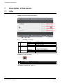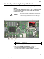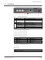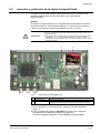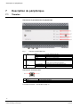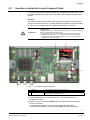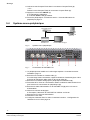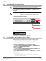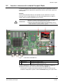
1
SISTORE CX1
Intelligent digital Video Codec
Inbetriebnahmeanleitung (DE)
Startup Manual (EN)
Manual de inicio (ES)
Manuel de mise en service (FR)
Manuale per iniziare (IT)
V3.6
Building Technologies
Fire Safety & Security Products
Data and design subject to change without notice.
Supply subject to availability.
© 2008 Copyright by Siemens Schweiz AG
We reserve all rights in this document and in the subject thereof. By acceptance of the document the recipient acknowledges these rights
and undertakes not to publish the document nor the subject thereof in full or in part, nor to make them available to any third party without our
prior express written authorization, nor to use it for any purpose other than for which it was delivered to him/her.
SISTORE CX1
Intelligent digital Video Codec
Inbetriebnahmeanleitung
V3.6
Building Technologies
Fire Safety & Security Products
Liefermöglichkeiten und technische Änderungen vorbehalten.
© 2008 Copyright by Siemens Schweiz AG
Wir behalten uns alle Rechte an diesem Dokument und an dem in ihm dargestellten Gegenstand vor. Der Empfänger erkennt diese Rechte
an und wird dieses Dokument nicht ohne unsere vorherige schriftliche Ermächtigung ganz oder teilweise Dritten zugänglich machen oder
außerhalb des Zweckes verwenden, zu dem es ihm übergeben worden ist.
1
Zu diesem Dokument..............................................................................5
2
2.1
2.2
2.2.1
2.2.2
2.2.3
2.2.4
2.3
2.4
Sicherheit.................................................................................................6
Zielgruppe .................................................................................................6
Allgemeine Sicherheitshinweise ...............................................................6
Transport...................................................................................................6
Montage ....................................................................................................6
Inbetriebnahme .........................................................................................7
Installation .................................................................................................7
Bedeutung von Signalwörtern...................................................................7
Bedeutung von Gefahrensymbolen ..........................................................7
3
Richtlinien und Normen .........................................................................8
4
Technische Daten ...................................................................................8
5
Bestellangaben........................................................................................9
6
Lieferumfang ...........................................................................................9
7
7.1
7.2
Gerätebeschreibung .............................................................................10
Anzeigen .................................................................................................10
Anschlüsse..............................................................................................11
8
Montage .................................................................................................12
9
9.1
9.2
9.3
9.4
9.5
9.6
9.7
Inbetriebnahme .....................................................................................13
Gerät öffnen oder schließen ...................................................................13
Gerät hoch- oder herunterfahren ............................................................14
Compact Flash Karte ein- und ausbauen ...............................................15
Anlagenbetrieb mit einem Gerät .............................................................16
Anlagenbetrieb mit mehreren Geräten ...................................................17
Ferritkern anbringen................................................................................18
IP-Adresse des Client-PCs einstellen .....................................................18
10
10.1
10.2
10.3
Konfiguration.........................................................................................19
Software installieren................................................................................19
Software SISTORE CX Config aufrufen .................................................19
SISTORE CX Konfigurationshandbuch aufrufen ....................................20
11
Entsorgung ............................................................................................20
3
Fire Safety & Security Products
Siemens Building Technologies
03.2009
Zu diesem Dokument
1
Zu diesem Dokument
In dieser Inbetriebnahmeanleitung finden Sie Anweisungen zur Montage und
Inbetriebnahme.
Anweisungen zur Konfiguration und Bedienung finden Sie im
Konfigurationshandbuch und dem Benutzerhandbuch auf der mitgelieferten CD.
Warenzeichen
Alle Produkte oder Firmennamen, die namentlich in diesem Handbuch erwähnt
werden, dienen nur zum Zwecke der Identifikation oder der Beschreibung und
können Warenzeichen oder eingetragene Warenzeichen der jeweiligen Eigentümer
sein.
SISTORE ist ein Warenzeichen der Fire & Security Products GmbH & Co. oHG.
Microsoft ist ein eingetragenes Warenzeichen und Windows ist ein Warenzeichen
der Microsoft Corporation.
Kontaktaufnahme
Wenn Sie Fragen oder Anregungen zum Produkt oder zu diesem Dokument
haben, wenden Sie sich bitte an Ihre örtliche SIEMENS-Niederlassung.
Siemens Building Technologies
Fire & Security Products GmbH & Co. oHG
D-76181 Karlsruhe
Besuchen Sie uns auch im Internet unter:
www.buildingtechnologies.siemens.com/.
Schulungen
Siemens Fire Safety & Security Products bietet für alle Produkte Schulungskurse
an.
5
Fire Safety & Security Products
Siemens Building Technologies
03.2009
Sicherheit
2
Sicherheit
2.1
Zielgruppe
Die Anweisungen in diesem Dokument richten sich nur an die folgende Zielgruppe:
Zielgruppe
Inbetriebsetzer
2.2
Qualifikation
Besitzt Fachkenntnisse
im Bereich
Gebäudeinstallationstechnik oder
Elektroinstallationen.
Tätigkeit
Zustand des Produkts
Nimmt das Produkt zum Produkt ist noch nicht
ersten Mal in Betrieb.
installiert und
konfiguriert.
Allgemeine Sicherheitshinweise
z
z
z
z
Lesen Sie vor der Bedienung des Gerätes die allgemeinen Sicherheitshinweise.
Bewahren Sie dieses Dokument zum Nachschlagen auf.
Geben Sie dieses Dokument bei der Weitergabe des Produktes mit.
Beachten Sie zusätzlich die landesspezifischen oder ortsüblichen
Sicherheitsnormen oder Gesetze für die Planung, die Konzeption, die
Installation, den Betrieb und die Entsorgung des Produktes.
Funkstörungen umliegender Geräte
z Dies ist eine Einrichtung der Klasse A. Diese Einrichtung kann im Wohnbereich
Funkstörungen verursachen; in diesem Fall kann vom Betreiber verlangt
werden, angemessene Maßnahmen durchzuführen.
Haftungsanspruch
z Schließen Sie das Gerät nur an, wenn es unbeschädigt ist und wenn der
Lieferumfang vollständig ist.
z Nehmen Sie nur Veränderungen am Gerät vor, die in diesem Dokument erwähnt
sind oder vom Hersteller genehmigt wurden.
z Verwenden Sie nur vom Hersteller genehmigte Ersatz- und Zubehörteile.
2.2.1
Transport
Geräteschaden bei Transport
z Bewahren Sie die Verpackung des Gerätes für den Weitertransport auf.
z Setzen Sie das Gerät keiner Erschütterung aus.
2.2.2
Montage
Kabelschaden durch Belastung
z Setzen Sie die Kabel keiner Zugbeanspruchung aus.
z Achten Sie darauf, dass Kabel nicht belastet, geknickt oder beschädigt werden.
6
Fire Safety & Security Products
Siemens Building Technologies
03.2009
Sicherheit
2.2.3
Inbetriebnahme
Geräteschaden durch den falschen Standort
z Halten Sie die vom Hersteller empfohlenen Umgebungsbedingungen ein (siehe
Kap. 4: Technische Daten).
z Betreiben Sie das Gerät nicht in der Nähe einer stark elektromagnetischen
Strahlungsquelle.
z Schützen Sie das Gerät vor Feuchtigkeit und Nässe.
z Betreiben Sie das Gerät nicht an staubigen Orten.
z Setzen Sie das Gerät keiner Erschütterung aus.
Geräteschaden durch unzureichende Belüftung
z Blockieren Sie nicht die Belüftungsöffnungen des Gerätes.
Geräteschaden durch überhöhte Spannung
z Schließen Sie das Gerät nur an Stromquellen mit der angegebenen Spannung
an. Auf dem Typenschild finden Sie Hinweise zur Spannungsversorgung.
2.2.4
Installation
Datenverlust bei Aktualisierung der Software
z Sichern Sie alle Daten bevor Sie die Software auf dem Gerät aktualisieren.
2.3
Bedeutung von Signalwörtern
Auf die Schwere der Gefahr wird mit Signalworten hingewiesen.
VORSICHT
WICHTIG
2.4
Gefahr von mittlerer bzw. leichter Körperverletzung oder Sachschaden
Gefahr von Funktionsstörungen
Bedeutung von Gefahrensymbolen
Warnung vor einer Gefahrenstelle
Warnung vor gefährlicher elektrischer Spannung
7
Fire Safety & Security Products
Siemens Building Technologies
03.2009
Richtlinien und Normen
3
Richtlinien und Normen
Die EG-Richtlinie 2004/108/EC „Elektromagnetische Verträglichkeit” wird nur mit einem Ferritkern
erfüllt (siehe Kap. 9.6: Ferritkern anbringen).
Das Produkt erfüllt die Anforderungen der nachfolgenden EG-Richtlinien.
Die EG-Konformitätserklärung wird zur Verfügung gestellt bei:
Siemens Building Technologies
Fire & Security Products GmbH & Co. oHG
76181 Karlsruhe
EG-Richtlinie 2004/108/EC „Elektromagnetische Verträglichkeit”
Die Konformität mit der EG-Richtlinie 2004/108/EC wird nachgewiesen durch die
Einhaltung folgender Normen:
Störaussendung:
Störfestigkeit:
4
EN 61000-6-4
EN 50130-4
Technische Daten
Anwendung
Umgebungstemperatur (Tmra)
Relative Luftfeuchtigkeit
Gewicht
Spannungsversorgung
Leistungsaufnahme
Steckplatz für Compact-Flash-Karte
Compact Flash Karte
Digitale Eingänge
Digitale Ausgänge
Batterietyp
Hutschiene
Abmessungen (B x H x T)
CX1
Codieren und decodieren von Videosignalen, Videoübertragung,
Videoaufzeichnung und Videoauswertung
-10 bis +50 °C
20 – 80 % ohne Kondensation
0,95 kg
12 – 24 V DC oder 24 V AC, max. 1,25 A
Die Spannungsversorgung für das Gerät muss den
Spezifikationen SELV (Safety Extra Low Voltage) und LPS
(Limited Power Source) der Norm EN 60950-1 entsprechen.
Max. 15 W
CF-Typ I: 42.8 x 36.4 x 3.3 mm
Empfohlene Compact Flash Karte: SanDisk Extreme® IV
Zulässiger Temperaturbereich: 0 – 70 °C
Minimale Übertragungsgeschwindigkeit: 1 MB/s r/w
Minimale Speicherkapazität: 4 GB
2
2
Varta 6032
Tragschiene 35 x 7,5 mm nach DIN EN 50022
192 x 44 x 110 mm
8
Fire Safety & Security Products
Siemens Building Technologies
03.2009
Bestellangaben
5
Bestellangaben
Typ
CX1 0/25
Art-Nr.
S24245-F5104-A1
CX1 EDS
S24245-P5101-A1
CX1 ODR
P54565-P1-A1
6
Bezeichnung
SISTORE CX1 Intelligent Digital Video Codec
1 Kamera – 25 ips
Zubehör, nicht im Lieferumfang enthalten!
EDS – Enhanced Detection Solution
Bewegungserkennung und Objektverfolgung
ODR – Object Detection/Removal
Erkennung zurückgelassener und entfernter
Objekte
Gewicht
0,95 kg
–
–
Lieferumfang
z
z
z
z
z
z
SISTORE CX1 in der bestellten Ausbauvariante
Software CD mit Konfigurationshandbuch und Benutzerhandbuch
Inbetriebnahmeanleitung
Spannungsversorgungsstecker
I/O Stecker
Klappferritkern Typ 74271132 der Firma Würth
9
Fire Safety & Security Products
Siemens Building Technologies
03.2009
Gerätebeschreibung
7
Gerätebeschreibung
7.1
Anzeigen
Anzeigen an der Gerätevorderseite
Fig. 1
Anzeigen SISTORE CX1
1
Video
2
3
Network
Storage
4
Power
Anzeige aus:
Rot:
Grün:
Orange:
Grün blinkend:
Anzeige aus:
Grün blinkend:
Anzeige aus:
Grün leuchtend:
Keine Kamera angeschlossen
Alarm, Initialisierung, Überhitzung
Kamerasignal liegt an
Livebild oder Aufnahme
Datenübertragung
Keine Videoaufzeichnung auf Compact Flash Karte ––
– oder –
keine Compact Flash Karte vorhanden
Aufnahme auf Compact Flash Karte
Gerät ist heruntergefahren
Gerät ist betriebsbereit
Anzeigen am LAN-Anschluss
1
2
Grün blinkend:
Anzeige aus:
Gelb leuchtend:
Datenübertragung
Physikalische Verbindung besteht nicht
Physikalische Verbindung besteht
Vergleichen Sie hierzu Kap.: "Anschlüsse", Seite 11.
10
Fire Safety & Security Products
Siemens Building Technologies
03.2009
Gerätebeschreibung
7.2
Anschlüsse
Fig. 2
Anschlüsse SISTORE CX1
1
2
3
4
1 Videoeingang
1 Videoausgang
1 Videoschleife
1 Abschlusswiderstand
5
6
7
USB 2.0
Ethernet RJ45
I/O Anschluss:
2 Digitale Eingänge
2 Digitale Ausgänge
8
Anschluss von 75 Ohm-BNC-Kabel (PAL)
Anschluss von 75 Ohm-BNC-Kabel (PAL)
Anschluss von 75 Ohm-BNC-Kabel
On: Videosignal nicht durchschleifen
Off: Videosignal zu anderem Videoeingang durchschleifen
max. 500 mA
10/100 Mbit Netzwerkanschluss
Schalten durch Relaiskontakte
Potential getrennt, Open-Collector-Ausgänge, 5 – 24 V,
max. 50 mA
RS485
Transparenter Datenkanal, PTZ Steuerung
Audio Eingänge/Ausgänge
Nicht unterstützt
Stromversorgungsanschluss 12 – 24 V DC oder 24 V AC, 15 W
Pinbelegung Anschlussblock 7
1
2
3
4
5
6
7
8
Audio Eingang (-)
Audio Eingang (+)
Audio Ausgang (-)
Audio Ausgang (+)
Nicht unterstützt
Nicht unterstützt
Digitaler Ausgang #1 (+)
Digitaler Ausgang #1 (-)
9
10
11
12
13
14
15
16
Digitaler Ausgang #2 (+)
Digitaler Ausgang #2 (-)
Digitaler Eingang #1 (+)
Digitaler Eingang #1 (-)
Digitaler Eingang #2 (+)
Digitaler Eingang #2 (-)
RS485 (D+)
RS485 (D-)
Pinbelegung Anschlussblock 8
1
2
3
GND / Erdung
12 – 24 V DC (-) oder 24 V AC
12 – 24 V DC (+) oder 24 V AC
11
Fire Safety & Security Products
Siemens Building Technologies
03.2009
Montage
8
Montage
WICHTIG
Überhitzung des Gerätes
Bei Überhitzung wird das Gerät automatisch heruntergefahren.
Î Die LED 1 an der Vorderseite des Gerätes leuchtet rot.
z Prüfen Sie den Mindestabstand von 10 cm zu den Belüftungslöchern am
Gehäusedeckel.
z Prüfen Sie die Umgebungstemperatur. Vergleichen Sie hierzu Kap.:
"Technische Daten", Seite 8.
Î Bei ausreichender Abkühlung wird das Gerät automatisch hochgefahren.
Gerät an die Hutschiene montieren
1. Schrauben Sie die empfohlene Hutschiene an die Wand.
Vergleichen Sie hierzu Kap.: "Technische Daten", Seite 8.
Geräte-/Anlagen- oder Personenschäden durch falsche Montage
Bei falscher Montage besteht die Gefahr, dass das Gerät herunterfällt.
VORSICHT
1. Achten Sie bei der Montage darauf, dass das Gerät an der Hutschiene richtig
einrastet.
2. Sichern Sie das Gerät mit Hilfe von Hutschienen-Endhaltern auf beiden
Seiten gegen seitliches Verschieben.
2. Hängen Sie das Gerät von oben in die Hutschiene ein.
3. Klappen Sie das Gerät herunter.
4. Sichern Sie das Gerät mit Hilfe von Hutschienen-Endhaltern auf beiden Seiten
gegen seitliches Verschieben.
Î Das Gerät ist montiert.
Gerät von der Hutschiene abmontieren
1. Ziehen Sie mit einem Schraubendreher die Lasche in der unteren Mitte des
Gerätes nach unten.
2. Entfernen Sie das Gerät.
Î Das Gerät ist abmontiert.
12
Fire Safety & Security Products
Siemens Building Technologies
03.2009
Inbetriebnahme
9
Inbetriebnahme
9.1
Gerät öffnen oder schließen
Fig. 3
SISTORE CX1 – Schrauben an der Gerätevorderseite
Gerät öffnen
1. Lösen Sie die Schrauben an der Gerätevorderseite.
2. Ziehen Sie den Gehäusedeckel vom Gerät.
Gerät schließen
1. Stecken Sie den Gehäusedeckel auf das Gerät.
2. Ziehen Sie die Schrauben an der Gerätevorderseite fest.
13
Fire Safety & Security Products
Siemens Building Technologies
03.2009
Inbetriebnahme
9.2
Gerät hoch- oder herunterfahren
Fig. 4
SISTORE CX1 – ON/OFF Schalter
1. Öffnen Sie das Gerät. Vergleichen Sie hierzu Kap.: "Gerät öffnen oder
schließen", Seite 13.
2. Halten Sie zum Herunterfahren des Gerätes die ON/OFF-Taste (1) ca. zwei
Sekunden gedrückt.
Î Das Gerät fährt herunter, dies kann einige Sekunden dauern.
Î Die Power LED (2) leuchtet nicht mehr, wenn das Gerät heruntergefahren ist.
3. Drücken Sie die ON/OFF-Taste (1).
Î Das Gerät fährt hoch.
Î Die Power LED (2) leuchtet.
4. Schließen Sie das Gerät. Vergleichen Sie hierzu Kap.: "Gerät öffnen oder
schließen", Seite 13.
14
Fire Safety & Security Products
Siemens Building Technologies
03.2009
Inbetriebnahme
9.3
Compact Flash Karte ein- und ausbauen
Die Compact Flash Karte ermöglicht eine lokale Videoaufzeichnung. Die
Aufzeichnungsdauer hängt vom Video-Stream und der Speicherkapazität ab.
Beispiel
Bei einer Speicherkapazität der Compact Flash Karte von 4 GB, einem Bildformat
von 4CIF bei Standard Qualität und einer Übertragungsgeschwindigkeit von
1 MB/s kann der Video-Stream ca. 2,5 Stunden aufgezeichnet werden.
Aufzeichnungsfehler bei falscher Compact Flash Karte
Bei nicht geeigneter Compact Flash Karte kann es zu Fehlern bei der
Aufzeichnung von Videodaten kommen.
z Achten Sie auf den zulässigen Temperaturbereich von 0 – 70 °C, auf die
minimal notwendige Übertragungsgeschwindigkeit von 1 MB/s und die
minimale Speicherkapazität von 4 GB. Vergleichen Sie hierzu Kap.:
"Technische Daten", Seite 8.
WICHTIG
Fig. 5
1
2
3
SISTORE CX1 Innenansicht
ON/OFF
Compact Flash
Power
An- oder Austaste
Compact Flash Slot
Anzeige aus: Gerät ist heruntergefahren
Anzeige an: Gerät ist betriebsbereit
1. Öffnen Sie das Gerät. Vergleichen Sie hierzu Kap.: "Gerät öffnen oder
schließen", Seite 13.
2. Halten Sie die ON/OFF-Taste (1) ca. zwei Sekunden gedrückt.
Î Das Gerät fährt herunter, dies kann einige Sekunden dauern.
Î Die Power LED (3) leuchtet nicht mehr, wenn das Gerät heruntergefahren ist.
15
Fire Safety & Security Products
Siemens Building Technologies
03.2009
Inbetriebnahme
3. Stecken Sie die Compact Flash Karte in den Compact Flash Slot (2).
– oder –
Ziehen Sie die Compact Flash Karte aus dem Compact Flash Slot (2).
4. Drücken Sie die ON/OFF-Taste (1).
Î Das Gerät fährt hoch.
Î Die Power LED (3) leuchtet.
5. Schließen Sie das Gerät. Vergleichen Sie hierzu Kap.: "Gerät öffnen oder
schließen", Seite 13.
9.4
Anlagenbetrieb mit einem Gerät
Fig. 6
Anlagenbetrieb mit einem Gerät
Fig. 7
Anschlüsse SISTORE CX1
1. Betreiben Sie das Gerät an der Hutschiene. Vergleichen Sie hierzu Kap.:
"Montage", Seite 12.
2. Schießen Sie eine Kamera an den Videoeingang (1) an.
Falls Durchschleifen erforderlich ist, stellen Sie den Abschlusswiderstand (4) auf
Off und schließen Sie weiterführende Videokabel an der Videoschleife (3) an.
3. Schließen Sie einen analogen Monitor an das SISTORE CX Gerät (2) an.
4. Schließen Sie den Client-PC an den Netzwerk-Switch und diesen mit dem
Netzwerkkabel an das Gerät (6) an.
5. Schließen Sie das Spannungsversorgungskabel zuerst an den SISTORE CX (8)
und danach an die Spannungsversorgung an.
6. Schalten Sie den analogen Monitor ein.
Î Es erscheint nach kurzer Zeit die IP-Adresse des SISTORE CX.
7. Schließen Sie den Client-PC an die Spannungsversorgung an.
8. Starten Sie den Client-PC.
9. Stellen Sie die IP-Adresse des Client-PCs ein. Vergleichen Sie hierzu Kap.: "IPAdresse des Client-PCs einstellen", Seite 18.
16
Fire Safety & Security Products
Siemens Building Technologies
03.2009
Inbetriebnahme
9.5
Anlagenbetrieb mit mehreren Geräten
Netzwerk-Switch
1 Kamera
SISTORE CX1
Client-PC
1 Kamera
SISTORE CX1
•
•
•
1 Kamera
SISTORE
CX1 / CX4 / CX8
Analoger Monitor
SISTORE CX1
Fig. 8
Anlagenbetrieb mit mehreren Geräten
Fig. 9
Anschlüsse SISTORE CX1
1. Betreiben Sie das Gerät an der Hutschiene. Vergleichen Sie hierzu Kap.:
"Montage", Seite 12.
2. Schließen Sie die Kamera an den Videoeingang (1) an.
Falls Durchschleifen erforderlich ist, stellen Sie den Abschlusswiderstand (4) auf
Off und schließen Sie weiterführende Videokabel an der Videoschleife (3) an.
3. Verbinden Sie alle SISTORE CX Geräte mit dem Netzwerk-Switch (6).
4. Schließen Sie einen oder mehrere Client-PCs mit dem Netzwerkkabel an den
Netzwerk-Switch an.
5. Schließen Sie Monitore an die Client-PCs an.
6. Um die IP-Adresse eines SISTORE CX Gerätes auszulesen, schließen Sie
einen analogen Monitor an das entsprechende Gerät (2) an.
7. Schließen Sie die Spannungsversorgungskabel zuerst an den SISTORE CX (8)
und danach an die Spannungsversorgungen an.
8. Schalten Sie den analogen Monitor ein.
Î Es erscheint nach kurzer Zeit die IP-Adresse des SISTORE CX.
9. Schließen Sie den Client-PC an die Spannungsversorgung an.
10.Starten Sie den Client-PC.
11.Stellen Sie die IP-Adresse des Client-PCs ein. Vergleichen Sie hierzu Kap.: "IPAdresse des Client-PCs einstellen", Seite 18.
17
Fire Safety & Security Products
Siemens Building Technologies
03.2009
Inbetriebnahme
9.6
Ferritkern anbringen
Die EG-Richtlinie 2004/108/EC „Elektromagnetische Verträglichkeit” wird nur mit einem Ferritkern
erfüllt.
Der Klappferritkern Typ 74271132 der Firma Würth ist im Lieferumfang enthalten.
z Der Abstand zwischen Ferritkern und Gerät darf max. 100 mm betragen.
z Falls das verwendete I/O Kabel nicht in den mitgelieferten Klappferritkern
WICHTIG
passt, verwenden Sie einen anderen Ferritkern mit den entsprechenden
elektrischen Eigenschaften.
1. Schließen Sie das I/O Kabel am I/O Anschluss an.
Fig. 10
1
2
3
Ferritkern um I/O Kabel
I/O Anschluss
I/O Kabel
Ferritkern
2. Bringen Sie um das I/O Kabel den Ferritkern an.
9.7
IP-Adresse des Client-PCs einstellen
Vorraussetzung:
Das System ist nicht an einen DHCP-Server angeschlossen.
1. Klicken Sie im Windows Start Menü auf Start > Einstellungen >
Systemsteuerung > Netzwerkverbindungen.
2. Klicken Sie mit der rechten Maustaste auf die ausgewählte Netzwerkverbindung.
3. Wählen Sie aus dem Kontextmenü den Menüpunkt Eigenschaften aus.
Î Das Dialogfenster Eigenschaften von Local Area Connection öffnet sich.
4. Wählen Sie ein Internetprotokoll (TCP/IP) aus.
5. Klicken Sie auf die Schaltfläche Eigenschaften.
Î Das Dialogfenster Eigenschaften von Internetprotokoll (TCP/IP) öffnet
sich.
6. Aktivieren Sie das Optionsfeld Folgende IP-Adresse verwenden.
7. Geben Sie IP-Adresse 169.254.xxx.xxx und Subnetzmaske 255.255.0.0 ein.
8. Klicken Sie auf die Schaltfläche OK.
9. Starten Sie Ihren Client-PC neu.
Î Das Gerät ist bereit für die Softwareinstallation. Vergleichen Sie hierzu Kap.:
"Software installieren", Seite 19.
18
Fire Safety & Security Products
Siemens Building Technologies
03.2009
Konfiguration
10
Konfiguration
10.1
Software installieren
Systemvoraussetzungen für den Client-PC
Für den Betrieb der SISTORE Client Software auf dem Client-PC empfehlen wir
Ihnen:
Prozessor
Arbeitsspeicher
Freie Festplattenkapazität
Betriebssystem
Grafikkarte
Bildschirmauflösung
Farbtiefe
Dual Core Prozessor
1 GB
5 GB
Windows XP SP2 oder Windows Vista
mit Unterstützung für DirectX 8 oder höher
min. 1024 x 768 Pixel
16 Bit oder 32 Bit (24 Bit nicht unterstützt)
Software installieren
1. Legen Sie die mitgelieferte CD in das CD-Laufwerk des Client-PCs ein.
Î Das Installationsprogramm wird automatisch gestartet.
2. Folgen Sie den Anweisungen des Installationsprogammes.
Î Die folgenden Softwareanwendungen werden installiert:
– SISTORE CX Config
– SISTORE CX Swap-Out Config
– SISTORE CX Client
– SISTORE CX Player
3. Starten Sie den Client-PC neu, wenn Sie dazu aufgefordert werden.
10.2
Software SISTORE CX Config aufrufen
1. Wählen Sie im Windows Start Menü Start > Programme > SIEMENS Video
Software Suite > SISTORE CX Config.
Fig. 11
SISTORE CX Startmenü
– oder –
Doppelklicken Sie auf die Desktop-Verknüpfung SISTORE CX Config.
Fig. 12
SISTORE CX Desktop-Verknüpfung
19
Fire Safety & Security Products
Siemens Building Technologies
03.2009
Entsorgung
2. Melden Sie sich folgendermaßen an:
Benutzername: admin Kennwort: admin
Î Die Software SISTORE CX Config ist aufgerufen.
10.3
SISTORE CX Konfigurationshandbuch aufrufen
Weitere Anweisungen zur Konfiguration finden Sie im SISTORE CX
Konfigurationshandbuch.
1. Wählen Sie im Windows Start Menü Start > Programme > SIEMENS Video
Software Suite > SISTORE CX Konfigurationshandbuch (vgl. Fig. 11).
Î Das SISTORE CX Konfigurationshandbuch ist aufgerufen.
11
Entsorgung
Alle Elektro- und Elektronikgeräte sind getrennt vom allgemeinen Hausmüll über dafür
staatlich vorgesehene Stellen zu entsorgen.
Wenn dieses Symbol eines durchgestrichenen Abfalleimers auf einem Produkt
angebracht ist, unterliegt dieses Produkt der europäischen Richtlinie 2002/96/EC.
Die sachgemäße Entsorgung und getrennte Sammlung von Altgeräten dienen der
Vorbeugung von potenziellen Umwelt- und Gesundheitsschäden. Sie sind eine
Voraussetzung für die Wiederverwendung und das Recycling gebrauchter Elektro- und
Elektronikgeräte. Ausführlichere Informationen zur Entsorgung Ihrer Altgeräte erhalten
Sie bei Ihrer Kommune, Ihrem Müllentsorgungsdienst oder dem Fachhändler, bei dem
Sie das Produkt erworben haben.
20
Fire Safety & Security Products
Siemens Building Technologies
03.2009
Herausgegeben von
Siemens Building Technologies Fire & Security Products
GmbH & Co. oHG
D-76181 Karlsruhe
www. buildingtechnologies.siemens.com
Dokument Nr.
A6V10059819
Ausgabe
26.03.2009
© 2009 Copyright by Siemens Schweiz AG
Liefermöglichkeiten und technische Änderungen vorbehalten.
Gedruckt in der Bundesrepublik Deutschland
auf umweltfreundlich chlorfrei gebleichtem Papier.
Inbetriebnahmeanleitung
SISTORE CX1
Intelligent digital Video Codec
Startup Manual
V3.6
Building Technologies
Fire Safety & Security Products
Data and design subject to change without notice.
Supply subject to availability.
© 2008 Copyright by Siemens Schweiz AG
We reserve all rights in this document and in the subject thereof. By acceptance of the document the recipient acknowledges these rights
and undertakes not to publish the document nor the subject thereof in full or in part, nor to make them available to any third party without our
prior express written authorization, nor to use it for any purpose other than for which it was delivered to him/her.
1
About this document ..............................................................................5
2
2.1
2.2
2.2.1
2.2.2
2.2.3
2.2.4
2.3
2.4
Safety .......................................................................................................6
Target readers...........................................................................................6
Work safety information ............................................................................6
Transport...................................................................................................6
Installation .................................................................................................6
Setup.........................................................................................................7
Installation .................................................................................................7
Meaning of the written warning notices ....................................................7
Meaning of the hazard symbols ................................................................7
3
Directives and standards .......................................................................8
4
Technical data .........................................................................................8
5
Details for ordering .................................................................................9
6
Scope of delivery ....................................................................................9
7
7.1
7.2
Description of the device .....................................................................10
LEDs .......................................................................................................10
Connections ............................................................................................11
8
Installation .............................................................................................12
9
9.1
9.2
9.3
9.4
9.5
9.6
9.7
Setup ......................................................................................................13
Opening/closing the device.....................................................................13
Switching the device on or off .................................................................14
Inserting and removing the Compact Flash card ....................................15
Single-device system ..............................................................................16
Multiple-device system............................................................................17
Installing the ferrite core..........................................................................18
Setting the IP address of the client PC ...................................................18
10
10.1
10.2
10.3
Configuration.........................................................................................19
Installing the software .............................................................................19
Starting the SISTORE CX Config software.............................................19
Opening the SISTORE CX Configuration Manual ..................................20
11
Disposal .................................................................................................20
3
Fire Safety & Security Products
Siemens Building Technologies
03.2009
About this document
1
About this document
This Startup Manual contains instructions for installation and setup.
For information on configuration and operation please refer to the Configuration
Manual and the User Manual on the accompanying CD.
Trademarks
All products or company names referred to explicitly in this manual are mentioned
only for purposes of identification or description and may be trademarks or
registered trademarks of their respective owners.
SISTORE is a trademark of Fire & Security Products GmbH & Co. oHG.
Microsoft is a registered trademark and Windows a trademark of Microsoft
Corporation.
Contacting us
If you have questions or suggestions regarding the product or this documentation,
please contact your local SIEMENS representative.
Siemens Building Technologies
Fire & Security Products GmbH & Co. oHG
D-76181 Karlsruhe
You can also visit our Web site at:www.buildingtechnologies.siemens.com/.
Training courses
Siemens Fire Safety & Security Products provides training courses for all products.
5
Fire Safety & Security Products
Siemens Building Technologies
03.2009
Safety
2
Safety
2.1
Target readers
The instructions in this document are designed only for the following target
readers:
2.2
Target readers
Qualification
Activity
Operational startup
personnel
Technical training for
building or electrical
installations.
Puts the product into
operation for the first
time.
Condition of the
product
The product is not yet
installed and
configured.
Work safety information
z
z
z
z
Read the general safety precautions before operating the device.
Keep this document for reference.
Always pass this document on together with the product.
Any national or local safety standards or laws that apply to the development,
design, installation, operation or disposal of a product must be adhered to in
addition to the instructions in the product documentation.
Radio interference with other devices in the environment
z This is a Class A device. This equipment may cause radio interference in a
residential installation. In this case the user is encouraged to perform
appropriate measures to correct the interference.
Liability claim
z Do not connect the device if it is damaged or any parts are missing.
z Do not make any changes or modifications to the device unless they are
expressly mentioned in this manual and have been approved by the
manufacturer.
z Use only spare parts and accessories that have been approved by the
manufacturer.
2.2.1
Transport
Damage during transport
z Keep the packaging material for future transportation.
z Do not expose the device to mechanical vibrations or shocks.
2.2.2
Installation
Cable damage due to mechanical load
z Do not apply tensile force on the cable.
z Make sure that cables are not under stress, kinked or damaged.
6
Fire Safety & Security Products
Siemens Building Technologies
03.2009
Safety
2.2.3
Setup
Damage due to unsuitable mounting location
z The environmental conditions recommended by the manufacturer must be
observed (see Section 4 Technical data).
z Do not operate the device close to sources of powerful electromagnetic
radiation.
z Protect the device against moisture.
z Do not operate the device in dusty places.
z Do not expose the device to mechanical vibrations or shocks.
Damage to the device due to lack of ventilation
z Do not block or cover the ventilation openings of the device.
Damage to the device due to overvoltage
z Connect the device only to power sources with the specified voltage. Voltage
supply requirements can be found on the type label.
2.2.4
Installation
Data loss after software update
z Make sure to backup all data before updating the software.
2.3
Meaning of the written warning notices
The severity of a hazard is indicated by the following written warning notices.
CAUTION
IMPORTANT
2.4
There is a risk of minor injuries or damage to property.
Malfunctioning may result
Meaning of the hazard symbols
Caution - Dangerous area!
Caution - Dangerous electrical voltage!
7
Fire Safety & Security Products
Siemens Building Technologies
03.2009
Directives and standards
3
Directives and standards
Compliance with the European Directive 2004/108/EC „Electromagnetic Compatibility” is achieved
only if the device is equipped with a ferrite core (see Section 9.6: Installing the ferrite core).
This product complies with the requirements of the following European directives.
The EU declaration of conformity is available to the responsible agencies at:
Siemens Building Technologies
Fire & Security Products GmbH & Co. oHG
76181 Karlsruhe
European Directive 2004/108/EC „Electromagnetic Compatibility”
Compliance with the European Directive 2004/108/EC has been proven by testing
according to the following standards:
Emitted interference:
Interference resistance:
4
EN 61000-6-4
EN 50130-4
Technical data
Application
Environmental temperature (TMRA)
Relative humidity
Weight
Power supply
Power consumption
Compact flash slot
Compact flash card
Digital inputs
Digital outputs
Battery
Top-hat rail
Dimensions (W x H x D)
CX1
Encoding and decoding of video signals, transmission, recording
and evaluation
-10 – +50 °C,
20 – 80 % without condensation
0.95 kg
12 – 24 V DC or 24 V AC, max. 1.25 A
The power supply for the device must comply with SELV (Safety
Extra Low Voltage) and LPS (Limited Power Source) requirements
and with the EN 60950-1 standard.
Max. 15 W
CF-type I: 42.8 x 36.4 x 3.3 mm
Recommended Compact flash card: SanDisk Extreme® IV
Permissible temperature range: 0 – 70 °C
Min. transmission speed: 1 MB/s r/w
Min. storage capacity: 4 GB
2
2
Varta 6032
Mounting rail 35 x 7.5 mm to DIN EN 50022
192 x 44 x 110 mm
8
Fire Safety & Security Products
Siemens Building Technologies
03.2009
Details for ordering
5
Details for ordering
Type
CX1 0/25
Order No.
S24245-F5104-A1
CX1 EDS
S24245–P5101–A1
CX1 ODR
P54565-P1-A1
6
Designation
SISTORE CX1 Intelligent Digital Video Codec
1 camera – 25 ips
Accessories, not included in the delivery!
EDS – Enhanced Detection Solution
Motion detection and object tracking
ODR – Object Detection/Removal
Detection of removed or left objects
Weight
0.95 kg
–
–
Scope of delivery
z
z
z
z
z
z
SISTORE CX1 model as ordered
Software CD with configuration manual and user manual
Startup manual
Voltage supply connector
I/O connector
Snap-on ferrite core type 74271132, manufacturer: Würth
9
Fire Safety & Security Products
Siemens Building Technologies
03.2009
Description of the device
7
Description of the device
7.1
LEDs
Displays on the front side of the device
Fig. 1
SISTORE CX1 displays
1
Video
2
3
Network
Storage
4
Power
No indicator:
Red:
Green:
Orange:
Blinking green:
No indicator:
Blinking green:
No indicator:
Lit green:
No camera connected
Alarm, initializing, overheated
Receiving camera signal
Live image or recording
Data transmission
No video recording on Compact Flash card
– or –
No Compact Flash card present
Recording on Compact Flash card
Device is switched off
Device is ready for operation
Displays on LAN connection
1
2
Blinking green:
No indicator:
Lit yellow:
Data transmission
No physical connection
Physical connection exists
See Section: "Connections", page 11.
10
Fire Safety & Security Products
Siemens Building Technologies
03.2009
Description of the device
7.2
Connections
Fig. 2
Connections of SISTORE CX1
1
2
3
4
1 video input
1 video output
1 video loop
1 terminating resistor
5
6
7
USB 2.0
Ethernet RJ45
I/O connector
2 digital inputs
2 digital outputs
8
RS485
Audio inputs/outputs
Power supply
Connection for 75 Ω BNC cable (PAL)
Connection for 75 Ω BNC cable (PAL)
Connection for 75 Ω BNC cable
On: no video signal loop-through
Off: video signal loops through to another video input
max. 500 mA
10/100 Mbit network connection
Switch via relay contacts
Potential disconnected, Open-Collector outputs, 5 – 24 V,
max. 50 mA
Transparent data channel, PTZ control
Not supported
12 – 24 V DC or 24 V AC, 15 W
Pin assignment terminal block 7
1
2
3
4
5
6
7
8
Audio input (-)
Audio input (+)
Audio output (-)
Audio output (+)
Not supported
Not supported
Digital output #1 (+)
Digital output #1 (-)
9
10
11
12
13
14
15
16
Digital output #2 (+)
Digital output #2 (-)
Digital input #1 (+)
Digital input #1 (-)
Digital input #2 (+)
Digital input #2 (-)
RS485 (D+)
RS485 (D-)
Pin assignment terminal block 8
1
2
3
GND
12 – 24 V DC (-) or 24 V AC
12 – 24 V DC (+) or 24 V AC
11
Fire Safety & Security Products
Siemens Building Technologies
03.2009
Installation
8
Installation
IMPORTANT
Overheating of the device
In case of overheating the device will shut down automatically.
Î LED 1 on the front of the device will be lit red.
z Check to ensure there is a minimum clearance of 10 cm to the ventilation
holes on the housing cover.
z Measure the ambient temperature. See Section: "Technical data", page 8.
Î When the device has cooled down sufficiently, it will boot up automatically.
Mounting the device to the top-hat rail
1. Screw the recommended top-hat rail to the wall.
See Section: "Technical data", page 8.
CAUTION
Risk of bodily injury or damage to the device/system due to incorrect
installation
If the device is not mounted correctly there is a risk that it will fall down.
1. Make sure that the device properly engages into the top-hat rail.
2. Secure the device against lateral displacement using rail stoppers on both
sides.
2. Hang the device in the top-hat rail from above.
3. Flip the device down.
4. Secure the device against lateral displacement using rail stoppers on both sides.
Î The device is now mounted.
Removing the device from the top-hat rail
1. Use a screwdriver to pull the tab in the middle of the bottom of the device down.
2. Remove the device.
Î The device is now dismounted.
12
Fire Safety & Security Products
Siemens Building Technologies
03.2009
Setup
9
Setup
9.1
Opening/closing the device
Fig. 3
SISTORE CX1 – Screws on the front side of the device
Opening the device
1. Remove the screws on the front side of the device.
2. Remove the housing cover.
Closing the device
1. Place the housing cover on the device.
2. Tighten the screws on the front side of the device.
13
Fire Safety & Security Products
Siemens Building Technologies
03.2009
Setup
9.2
Switching the device on or off
Fig. 4
SISTORE CX1 – ON/OFF switch
1. Open the device. See Section: "Opening/closing the device", page 13.
2. To shut down the device, press the ON/OFF key (1) for approx. 2 seconds.
Î The device switches off, which can take several seconds.
Î Once the device is switched off, the Power LED (2) will no longer be lit.
3. Press the ON/OFF key (1).
Î The device boots up.
Î The Power LED (2) lights up.
4. Close the device. See Section: "Opening/closing the device", page 13.
14
Fire Safety & Security Products
Siemens Building Technologies
03.2009
Setup
9.3
Inserting and removing the Compact Flash card
The Compact Flash card enables local video recording. The length of the recording
depends on the video stream and on the storage capacity.
Example
If the Compact Flash card has a storage capacity of 4 GB, an image format of 4CIF
at standard quality and a transfer rate of 1 MB/s, then the video stream can be
recorded for approx. 2.5 hours.
IMPORTANT
Fig. 5
1
2
3
Recording errors when using the wrong Compact Flash card
Using an improper Compact Flash card can cause errors upon recording video
data.
z Make sure the card meets the requirements for the permissible temperature
range of 0 – 70 °C, the minimum required transfer rate of 1 MB/s and the
minimum storage capacity of 4 GB. See Section: "Technical data", page 8.
SISTORE CX1 interior view
ON/OFF
Compact Flash
Power
Switch for turning on or off
Compact flash slot
Display off: Device is switched off
Display on: Device is ready for operation
1. Open the device. See Section: "Opening/closing the device", page 13.
2. Press and hold the ON/OFF switch (1) for approx. 2 seconds.
Î The device switches off, which can take several seconds.
Î Once the device is switched off, the Power LED (3) will no longer be lit.
15
Fire Safety & Security Products
Siemens Building Technologies
03.2009
Setup
3. Insert the Compact Flash card in the Compact Flash slot (2).
– OR –
Remove the Compact Flash card from the Compact Flash slot (2).
4. Press the ON/OFF key (1).
Î The device boots up.
Î The Power LED (3) lights up.
5. Close the device. See Section: "Opening/closing the device", page 13.
9.4
Single-device system
Network Switch
Client-PC
1 camera
SISTORE CX1
Fig. 6
Single-device system
Fig. 7
Connections of SISTORE CX1
Analog Monitor
1. Operate the device on the top-hat rail. See Section: "Installation", page 12.
2. Connect a camera to the video input (1).
If loop-through is necessary, set the terminating resistor (4) to Off and connect
the video cable extension to the video loop (3).
3. Connect an analog monitor to the SISTORE CX device (2).
4. Connect the client PC to the network switch, and use the network cable provided
to connect the switch to the device (6).
5. Connect the power supply cable to the SISTORE CX (8) first and then to the
power source.
6. Switch on the analog monitor.
Î After a short wait, the IP address of the SISTORE CX will appear on the
screen.
7. Connect the client PC to the power supply.
8. Start the client PC.
9. Set the IP address of the client PC. See Section: "Setting the IP address of the
client PC", page 18.
16
Fire Safety & Security Products
Siemens Building Technologies
03.2009
Setup
9.5
Multiple-device system
Network- Switch
1 Camera
SISTORE CX1
Client-PC
1 Camera
SISTORE CX1
•
•
•
1 Camera
SISTORE
CX 1 / CX 4 / CX8
Analog Monitor
SISTORE CX1
Fig. 8
Multiple-device system
Fig. 9
SISTORE CX1 connections
1. Operate the device on the top-hat rail. See Section: "Installation", page 12.
2. Connect the camera to the video input (1).
If loop-through is necessary, set the terminating resistor (4) to Off and connect
the video cable extension to the video loop (3).
3. Connect all the SISTORE CX devices to the network switch (6).
4. Connect one or more client PCs to the network switch using the network cable
provided.
5. Connect the monitors to the client PCs.
6. To display the IP address of a SISTORE CX device, connect an analog monitor
to the appropriate device (2).
7. Connect the power supply cables to the SISTORE CX (8) first and then to the
power sources.
8. Switch on the analog monitor.
Î After a short wait, the IP address of the SISTORE CX will appear on the
screen.
9. Connect the client PC to the power supply.
10.Start the client PC.
11.Set the IP address of the client PC. See Section: "Setting the IP address of the
client PC", page 18.
17
Fire Safety & Security Products
Siemens Building Technologies
03.2009
Setup
9.6
Installing the ferrite core
Compliance with the European Directive 2004/108/EC „Electromagnetic Compatibility” will be
achieved only if the device is equipped with a a ferrite core.
The snap-on ferrite core type 74271132 (manufacturer: Würth) is included in the
delivery.
z The distance between the ferrite core and the device must not exceed 100
IMPORTANT
mm.
z In case the I/O cable used should not fit into the snap-on ferrite core supplied,
another ferrite core with the same electrical properties has to be used.
1. Connect the I/O cable to the I/O port.
Fig. 10
1
2
3
Ferrite core snapped onto the I/O cable
I/O connector
I/O cable
Ferrite core
2. Snap the ferrite core onto the I/O cable.
9.7
Setting the IP address of the client PC
Prerequisite:
The system is not connected to a DHCP server.
1. Select Start > Settings >
Control Panel > Network Connections in the Windows Start menu.
2. Right-click on the selected network connection.
3. Select Properties in the context menu.
Î The Local Area Connection Properties dialog box appears.
4. Select an Internet protocol (TCP/IP).
5. Click on Properties.
Î The Internet Protocol (TCP/IP) Properties dialog box appears.
6. Activate the option Use the following IP address.
7. Enter 169.254.xxx.xxx for the IP address and 255.255.0.0 for the subnet
mask.
8. Click OK.
9. Restart your client PC.
Î The device is now ready for software installation. See Section: "Installing the
software", page 19.
18
Fire Safety & Security Products
Siemens Building Technologies
03.2009
Configuration
10
Configuration
10.1
Installing the software
System requirements for the client PC
The PC on which the SISTORE Client Software is installed should meet the
following requirements:
Processor
RAM
Available hard drive
capacity
Operating system
Graphics card
Screen resolution
Colour depth
Dual Core Prozessor
1 MB
5 GB
Windows XP or Windows Vista
with support for DirectX 8 (or later version)
min. 1024 x 768 pixels
16 bit or 32 bit (24 bit not supported)
Installing the software
1. Place the CD in the CD drive of the client PC.
Î The installation program is started automatically.
2. Follow the instructions of the installation program.
Î The following software applications will be installed:
– SISTORE CX Config
– SISTORE CX Swap-Out Config
– SISTORE CX Client
– SISTORE CX Player
3. Restart the client PC when you are prompted to do so.
10.2
Starting the SISTORE CX Config software
1. Select Start > Programs > SIEMENS Video Software Suite > SISTORE CX
Config in the Windows start menu.
Fig. 11
SISTORE CX start menu
– OR –
Double click on the desktop shortcut SISTORE CX Config.
Fig. 12
SISTORE CX desktop shortcut
19
Fire Safety & Security Products
Siemens Building Technologies
03.2009
Disposal
2. Log on to the server using the following user name and password.
User name: admin Password: admin
Î The SISTORE CX Config software has been started.
10.3
Opening the SISTORE CX Configuration Manual
For further information on configuration please refer to the SISTORE CX
Configuration Manual.
1. Select Start > Programs > SIEMENS Video Software Suite > SISTORE CX
Configuration Manual in the Windows start menu (see Fig. 11)
Î The SISTORE CX Configuration Manual is opened.
11
Disposal
All electrical and electronic products should be disposed of separately from the
municipal waste stream via designated collection facilities appointed by the
government or the local authorities.
This crossed-out wheeled bin symbol on the product means the product is covered by
the European Directive 2002/96/EC.
The correct disposal and separate collection of your old appliance will help prevent
potential negative consequences for the environment and human health. It is a
precondition for reuse and recycling of used electrical and electronic equipment. For
more detailed information about disposal of your old appliance, please contact your city
office, waste disposal service or the shop where you purchased the product.
20
Fire Safety & Security Products
Siemens Building Technologies
03.2009
Issued by
Siemens Building Technologies Fire & Security Products
GmbH & Co. oHG
D-76181 Karlsruhe
www.buildingtechnologies.siemens.com
Document No.
A6V10059819
Edition
26.03.2009
© 2008 Copyright by Siemens Schweiz AG
Data and design subject to change without notice.
Supply subject to availability.
Printed in the Federal Republic of Germany
on environment-friendly chlorine-free paper.
Startup manual
SISTORE CX1
Códec de vídeo digital
inteligente
Manual de inicio
V3.6
Building Technologies
Fire Safety & Security Products
Datos y diseño sujetos a modificación sin previo aviso. Suministro sujeto a existencias.
© 2008 Copyright Siemens Schweiz AG
El fabricante se reserva todos los derechos sobre este documento y el asunto en él tratado. Al aceptar este documento, el receptor
reconoce estos derechos y se compromete a no publicar el documento ni el asunto en él tratado ya sea total o parcialmente, y a no ponerlo
a disposición de terceros sin la previa autorización por escrito del fabricante ni a usarlo para otros fines que no sean los establecidos al
entregarle el documento.
1
Acerca de este documento ....................................................................5
2
2.1
2.2
2.2.1
2.2.2
2.2.3
2.2.4
2.3
2.4
Seguridad.................................................................................................6
A quién va destinado este documento......................................................6
Información sobre seguridad laboral.........................................................6
Transporte.................................................................................................6
Instalación .................................................................................................6
Preparación...............................................................................................7
Instalación .................................................................................................7
Significado de los avisos escritos .............................................................7
Significado de los símbolos de peligro .....................................................7
3
Directivas y normas................................................................................8
4
Datos técnicos.........................................................................................8
5
Referencias de pedido............................................................................9
6
Componentes ..........................................................................................9
7
7.1
7.2
Descripción del dispositivo .................................................................10
LED .........................................................................................................10
Conexiones .............................................................................................11
8
Instalación .............................................................................................12
9
9.1
9.2
9.3
9.4
9.5
9.6
9.7
Preparación ...........................................................................................13
Apertura / cierre del dispositivo...............................................................13
Encender o apagar el dispositivo............................................................14
Inserción y extracción de la tarjeta Compact Flash ................................15
Sistema de dispositivo único...................................................................16
Sistema de varios dispositivos................................................................17
Instalación del núcleo de ferrita ..............................................................18
Establecer la dirección IP del PC cliente ................................................18
10
10.1
10.2
10.3
Configuración........................................................................................19
Instalación del software ..........................................................................19
Inicio del software SISTORE CX Config.................................................19
Apertura del manual de configuración de SISTORE CX ........................20
11
Eliminación ............................................................................................20
3
Fire Safety & Security Products
Siemens Building Technologies
03.2009
Acerca de este documento
1
Acerca de este documento
Este manual de inicio contiene instrucciones de instalación y configuración.
Para obtener información sobre la configuración y el manejo, consulte el manual
de configuración y el manual de usuario en el CD incluido.
Marcas comerciales
Todos los nombres de productos o empresas mencionados de forma explícita en
este manual sólo aparecen a efectos de identificación o descripción, y pueden ser
marcas comerciales o registradas de sus respectivos propietarios.
SISTORE es una marca comercial de Fire & Security Products GmbH & Co. oHG.
Microsoft es una marca comercial registrada, y Windows es una marca comercial
de Microsoft Corporation.
Contacto
Si tiene preguntas o sugerencias con respecto al producto o a esta
documentación, póngase en contacto con su representante de SIEMENS local.
Siemens Building Technologies
Fire & Security Products GmbH & Co. oHG
D-76181 Karlsruhe
También puede visitar nuestro sitio Web en:
www.buildingtechnologies.siemens.com/.
Cursos de formación
Siemens Fire Safety & Security Products ofrece cursos de formación para todos
los productos.
5
Fire Safety & Security Products
Siemens Building Technologies
03.2009
Seguridad
2
Seguridad
2.1
A quién va destinado este documento
Las instrucciones de este documento están destinadas sólo a los siguientes
lectores:
A quién va destinado
este documento
Personal de puesta en
funcionamiento
2.2
Cualificación
Actividad
Formación técnica para
instalaciones eléctricas
o de edificios.
Realiza la primera
puesta en
funcionamiento del
producto.
Condición del
producto
El producto aún no está
instalado y configurado.
Información sobre seguridad laboral
z
z
z
z
Lea las precauciones de seguridad generales antes de utilizar el dispositivo.
Guarde este documento como referencia.
Este documento siempre debe acompañar al producto.
Cualesquiera normas de seguridad nacionales o locales que sean de
cumplimiento en el desarrollo, el diseño, la instalación, el manejo o el
desechado de un producto, deben cumplirse junto con las mencionadas en la
documentación del producto.
Interferencias de radio con otros dispositivos del entorno
z Este dispositivo es de Clase A. Este equipo puede originar interferencias de
radio en una instalación residencial. En ese caso, se recomienda al usuario que
adopte las medidas adecuadas para corregir dichas interferencias.
Declaración de responsabilidad
z No conecte el dispositivo si está dañado o faltan piezas.
z No realice cambios ni modificaciones en el dispositivo a no ser que se
mencionen expresamente en este manual y los haya aprobado el fabricante.
z Utilice sólo piezas de recambio o accesorios aprobados por el fabricante.
2.2.1
Transporte
Daños durante el transporte
z Guarde el material de embalaje para futuros transportes.
z No exponga el dispositivo a las vibraciones mecánicas o golpes.
2.2.2
Instalación
Daño en los cables por carga mecánica
z No tense los cables.
z Asegúrese de que los cables no quedan tirantes, enrollados o dañados.
6
Fire Safety & Security Products
Siemens Building Technologies
03.2009
Seguridad
2.2.3
Preparación
Daños por una ubicación de instalación inadecuada
z Se deben respetar las condiciones ambientales recomendadas por el fabricante
(consulte la sección 4 Datos técnicos).
z No utilice el dispositivo cerca de fuentes de radiación electromagnética
potentes.
z Proteja el dispositivo de la humedad.
z No utilice el dispositivo en lugares polvorientos.
z No exponga el dispositivo a las vibraciones mecánicas o golpes.
Daños en el dispositivo por falta de ventilación
z No bloquee ni cubra las aberturas de ventilación del dispositivo.
Daños en el dispositivo por sobretensión
z Conecte el dispositivo sólo a fuentes de corriente con el voltaje especificado. En
la etiqueta de tipo pueden leerse los requisitos de suministro de voltaje.
2.2.4
Instalación
Pérdida de datos tras la actualización del software
z Asegúrese de realizar copias de seguridad de todos los datos antes de
actualizar el software.
2.3
Significado de los avisos escritos
Los siguientes avisos escritos indican la gravedad de un peligro.
PRECAUCIÓN
IMPORTANTE
2.4
Existe un riesgo de daños físicos menores o daños materiales.
Puede producir un mal funcionamiento.
Significado de los símbolos de peligro
Precaución: área peligrosa
Precaución: voltaje peligroso
7
Fire Safety & Security Products
Siemens Building Technologies
03.2009
Directivas y normas
3
Directivas y normas
La conformidad con la Directiva europea 2004/108/EC "Compatibilidad electromagnética” se cumple
únicamente si el dispositivo está equipado con un núcleo de ferrita (consulte la
sección 9.6: Instalación del núcleo de ferrita).
Este producto cumple los requisitos de las siguientes directivas europeas:
La declaración de conformidad de la UE está disponible para las agencias
responsables en:
Siemens Building Technologies
Fire & Security Products GmbH & Co. oHG
76181 Karlsruhe
Directiva europea 2004/108/EC "Compatibilidad electromagnética"
La conformidad con la directiva europea 2004/108/EC ha sido probada según las
normas siguientes:
Interferencia emitida:
Resistencia de la
interferencia:
4
EN 61000-6-4
EN 50130-4
Datos técnicos
Aplicación
CX1
Codificación y descodificación de señales de vídeo, transmisión,
grabación y evaluación
Temperatura ambiente
-10 – +50 °C,
Humedad relativa
Peso
20 – 80 % sin condensación
0,95 kg
Alimentación
12 – 24 V CC o 24 V CA, máx. 1,25 A
La fuente de alimentación del dispositivo debe cumplir con los
requisitos de SELV (Voltaje extra-bajo de seguridad) y LPS (Fuente
de alimentación limitada), y con la norma EN 60950-1.
Consumo de energía
Máx. 15 W
Ranura Compact Flash
CF tipo I: 42,8 x 36,4 x 3,3 mm
Tarjeta Compact Flash
Tarjeta Compact Flash recomendada: SanDisk Extreme® IV
Rango de temperaturas permisibles: 0 – 70 °C
Velocidad de transmisión mín.: 1 MB/s l/e
Capacidad de almacenamiento mínima: 4 GB
Entradas digitales
2
Salidas digitales
2
Batería
Varta 6032
Raíl simétrico
Raíl de montaje 35 x 7,5 mm conforme a DIN EN 50022
Dimensiones (An. x Al. x Pr.)
192 x 44 x 110 mm
8
Fire Safety & Security Products
Siemens Building Technologies
03.2009
Referencias de pedido
5
Referencias de pedido
Tipo
CX1 0/25
Nº de pedido
S24245-F5104-A1
CX1 EDS
S24245–P5101–A1
CX1 ODR
P54565-P1-A1
6
Nombre
Códec de vídeo digital inteligente SISTORE CX1
1 cámara – 25 ips
Los accesorios no se incluyen en la entrega
EDS – Enhanced Detection Solution
Detección de movimiento y seguimiento de objetos
Peso
0,95 kg
ODR – Detección y eliminación de objetos
Detección de objetos retirados o abandonados
–
–
Componentes
z
z
z
z
z
z
Modelo SISTORE CX1 pedido
CD de software con manual de configuración y manual de usuario
Manual de inicio
Conector de alimentación
Conector E/S
Núcleo de ferrita de arandela 74271132, fabricante: Würth
9
Fire Safety & Security Products
Siemens Building Technologies
03.2009
Descripción del dispositivo
7
Descripción del dispositivo
7.1
LED
Indicadores del lado delantero del dispositivo
Fig. 1
1
Indicadores de SISTORE CX1
Vídeo
2
3
Sin indicador:
Rojo:
Verde:
Naranja:
Red
Verde intermitente
Almacenamiento Sin indicador:
4
Alimentación
Verde intermitente
Sin indicador:
Verde fijo:
Ninguna cámara conectada
Alarma, iniciando, sobrecalentamiento
Recibiendo señal de la cámara
Imagen o grabación en directo
Transmisión de datos
No hay grabación de vídeo en Compact Flash — o –
No hay tarjeta Compact Flash
Grabación en tarjeta Compact Flash
Dispositivo apagado
Dispositivo preparado para el funcionamiento
Indicadores de conexión LAN
1
2
Verde intermitente
Sin indicador:
Luz amarilla:
Transmisión de datos
No hay conexión física
Existe conexión física
Consulte la sección: "Conexiones", página 11.
10
Fire Safety & Security Products
Siemens Building Technologies
03.2009
Descripción del dispositivo
7.2
Conexiones
Fig. 2
Conexiones de SISTORE CX1
1
2
3
4
1 entrada de vídeo
1 salida de vídeo
1 interconexión de vídeo
1 resistor de terminación
5
6
7
USB 2.0
Ethernet RJ45
Conector E/S
2 entradas digitales
2 salidas digitales
8
RS485
Entradas/salidas de audio
Alimentación
Conexión para cable BNC de 75 Ω (PAL)
Conexión para cable BNC de 75 Ω (PAL)
Conexión para cable BNC de 75 Ω
Act.: no hay interconexión de señal de vídeo
Desact.: hay interconexión de la señal de vídeo a otra entrada
de vídeo
máx. 500 mA
Conexión de red de 10/100 Mbits
Conmutación mediante contactos de relé
Potencial desconectado, salidas de colector abierto, 5 – 24 V,
máx. 50 mA
Canal de datos transparente, control PTZ
No se admite
12 – 24 V CC o 24 V CA, 15 W
Asignación de contactos bloque terminal 7
1
2
3
4
5
6
7
8
Entrada de audio (-)
Entrada de audio (+)
Salida de audio (-)
Salida de audio (+)
No se admite
No se admite
Salida digital nº 1 (+)
Salida digital nº 1 (-)
9
10
11
12
13
14
15
16
Salida digital nº 2 (+)
Salida digital nº 2 (-)
Entrada digital nº 1 (+)
Entrada digital nº 1 (-)
Entrada digital nº 2 (+)
Entrada digital nº 2 (-)
RS485 (D+)
RS485 (D-)
Asignación de contactos bloque terminal 8
1
2
3
Masa
12 – 24 V CC (-) o 24 V CA
12 – 24 V CC (+) o 24 V CA
11
Fire Safety & Security Products
Siemens Building Technologies
03.2009
Instalación
8
Instalación
IMPORTANTE
Sobrecalentamiento del dispositivo
En caso de sobrecalentamiento el dispositivo se apaga automáticamente.
Î El LED 1 en la parte delantera del dispositivo se encenderá en rojo.
z Asegúrese de que hay un espacio mínimo de 10 cm alrededor de los orificios
de ventilación de la cubierta de la carcasa.
z Mida la temperatura ambiente. Consulte la sección: "Datos técnicos", página
8.
Î Cuando el dispositivo se haya enfriado lo suficiente, se iniciará de forma
automática.
Montaje del dispositivo en el raíl simétrico
1. Atornille el raíl simétrico recomendado a la pared.
Consulte la sección: "Datos técnicos", página 8.
PRECAUCIÓN
Existe riesgo de lesiones corporales o daños en el dispositivo/sistema si
no se instala correctamente
Si el dispositivo no se instala correctamente, existe el riesgo de que caiga.
1. Asegúrese de que el dispositivo está correctamente fijado al raíl simétrico.
2. Coloque topes a ambos lados del dispositivo para evitar que se desplace
lateralmente.
2. Cuelgue el dispositivo de la parte superior del raíl simétrico.
3. Dé la vuelta al dispositivo.
4. Coloque topes a ambos lados del dispositivo para evitar que se desplace
lateralmente.
Î El dispositivo ya está instalado.
Desmontaje del dispositivo del raíl simétrico.
1. Use un destornillador para presionar la pestaña en el centro de la base del
dispositivo.
2. Retire el dispositivo.
Î El dispositivo ya está desinstalado.
12
Fire Safety & Security Products
Siemens Building Technologies
03.2009
Preparación
9
Preparación
9.1
Apertura / cierre del dispositivo
Fig. 3
SISTORE CX1 – Tornillos en la parte delantera del dispositivo
Apertura del dispositivo
1. Quite los tornillos de la parte delantera del dispositivo.
2. Quite la cubierta de la carcasa.
Cierre del dispositivo
1. Coloque la cubierta de la carcasa del dispositivo.
2. Apriete los tornillos en la parte delantera del dispositivo.
13
Fire Safety & Security Products
Siemens Building Technologies
03.2009
Preparación
9.2
Encender o apagar el dispositivo
Fig. 4
SISTORE CX1 – Interruptor ACT/DES
1. Abra el dispositivo. Consulte la sección: "Apertura / cierre del dispositivo",
página 13.
2. Para apagar el dispositivo, pulse el interruptor ACT/DES (1) durante unos 2
segundos.
Î El dispositivo se apaga transcurridos unos segundos.
Î Una vez apagado el dispositivo, el LED Power (2) estará apagado.
3. Pulse el interruptor ACT/DES (1).
Î El dispositivo se inicia.
Î El LED Power (2) se ilumina.
4. Cierre el dispositivo. Consulte la sección: "Apertura / cierre del dispositivo",
página 13.
14
Fire Safety & Security Products
Siemens Building Technologies
03.2009
Preparación
9.3
Inserción y extracción de la tarjeta Compact Flash
La tarjeta Compact Flash permite grabar vídeo localmente. La duración de la
grabación depende de la secuencia de vídeo y de la capacidad de
almacenamiento.
Ejemplo
Si la tarjeta Compact Flash tiene una capacidad de almacenamiento de 4 GB, el
formato de imagen es 4CIF en calidad estándar y la velocidad de transferencia
1 MB/s, la secuencia de vídeo se puede grabar en aprox. 2,5 horas.
IMPORTANTE
Fig. 5
1
2
3
Errores de grabación al usar una tarjeta Compact Flash incorrecta
El uso de una tarjeta Compact Flash inadecuada puede producir errores en la
grabación de vídeo.
z Asegúrese de que la tarjeta cumple los requisitos de rango de temperaturas
permisibles 0 – 70 °C, velocidad de transferencia mínima de 1 MB/s y
capacidad de almacenamiento mínima de 4 GB. Consulte la sección: "Datos
técnicos", página 8.
Vista interior de SISTORE CX1
ACT/DES
Compact Flash
Alimentación
Interruptor de encendido y apagado
Ranura Compact Flash
Indicador apagado: Dispositivo apagado
Indicador encendido: Dispositivo preparado para el funcionamiento
1. Abra el dispositivo. Consulte la sección: "Apertura / cierre del dispositivo",
página 13.
2. Pulse y mantenga el interruptor ACT/DES (1) durante unos 2 segundos.
Î El dispositivo se apaga transcurridos unos segundos.
Î Una vez apagado el dispositivo, el LED Power (3) estará apagado.
15
Fire Safety & Security Products
Siemens Building Technologies
03.2009
Preparación
3. Inserte la tarjeta Compact Flash en la ranura Compact Flash (2).
–O–
Extraiga la tarjeta Compact Flash de la ranura Compact Flash (2).
4. Pulse el interruptor ACT/DES (1).
Î El dispositivo se inicia.
Î El LED Power (3) se ilumina.
5. Cierre el dispositivo. Consulte la sección: "Apertura / cierre del dispositivo",
página 13.
9.4
Sistema de dispositivo único
Conmutador de la red
Client -PC
1 cámara
SISTORE CX 1
Fig. 6
Sistema de dispositivo único
Fig. 7
Conexiones de SISTORE CX1
Monitor analógico
1. Funcionamiento del dispositivo montado en el raíl simétrico. Consulte la
sección: "Instalación", página 12.
2. Conecte una cámara a la entrada de vídeo (1).
Si es necesario realizar alguna interconexión, coloque el resistor de terminación
4 en la posición Desact. y conecte la extensión del cable de vídeo a la
interconexión de vídeo (3).
3. Conecte un monitor analógico al dispositivo SISTORE CX (2).
4. Conecte el PC cliente al conmutador de la red y utilice el cable de red incluido
para conectar el conmutador al dispositivo (6).
5. Conecte el cable de alimentación primero a SISTORE CX8 (8) y luego al
enchufe de alimentación.
6. Encienda el monitor analógico.
Î En breves momentos, la dirección IP de SISTORE CX aparecerá en la
pantalla.
7. Conecte el PC cliente a la corriente.
8. Inicie el PC cliente.
9. Establezca la dirección IP del PC cliente. Consulte la sección: "Establecer la
dirección IP del PC cliente", página 18.
16
Fire Safety & Security Products
Siemens Building Technologies
03.2009
Preparación
9.5
Sistema de varios dispositivos
Conmutador de la red
1 cámara
SISTORE CX 1
Client - PC
1 cámara
SISTORE CX 1
•
•
•
1 cámara
SISTORE
CX 1 / CX 4 / CX8
Monitor analógico
SISTORE CX 1
Fig. 8
Sistema de varios dispositivos
Fig. 9
Conexiones de SISTORE CX1
1. Funcionamiento del dispositivo montado en el raíl simétrico. Consulte la
sección: "Instalación", página 12.
2. Conecte la cámara a la entrada de vídeo (1).
Si es necesario realizar alguna interconexión, coloque el resistor de terminación
4 en la posición Desact. y conecte la extensión del cable de vídeo a la
interconexión de vídeo (3).
3. Conecte todos los dispositivos SISTORE al conmutador de la red (6).
4. Conecte uno o varios PC clientes al conmutador de red mediante el cable de
red suministrado.
5. Conecte los monitores a los PC clientes.
6. Para mostrar la dirección IP de un dispositivo SISTORE CX, conecte un monitor
analógico al dispositivo (2).
7. Conecte los cables de alimentación primero al SISTORE CX (8) y luego a los
enchufes de alimentación.
8. Encienda el monitor analógico.
Î En breves momentos, la dirección IP de SISTORE CX aparecerá en la
pantalla.
9. Conecte el PC cliente a la corriente.
10.Inicie el PC cliente.
11.Establezca la dirección IP del PC cliente. Consulte la sección: "Establecer la
dirección IP del PC cliente", página 18.
17
Fire Safety & Security Products
Siemens Building Technologies
03.2009
Preparación
9.6
Instalación del núcleo de ferrita
La conformidad con la Directiva europea 2004/108/EC "Compatibilidad electromagnética” se cumple
únicamente si el dispositivo está equipado con un núcleo de ferrita.
El núcleo de ferrita de arandela 74271132 (fabricante: Würth) se incluye en la
entrega.
z La distancia entre el núcleo de ferrita y el dispositivo no debe superar los 100
mm.
IMPORTANTE
z En caso de que el cable de E/S no encaje en el núcleo de ferrita
suministrado, debe utilizar otro núcleo con las mismas propiedades
eléctricas.
1. Conecte el cable de E/S al puerto de E/S.
Fig. 10
1
2
3
Núcleo de ferrita instalado en el cable de E/S.
Conector de E/S
Cable de E/S
Núcleo de ferrita
2. Coloque el núcleo de ferrita en el cable de E/S.
9.7
Establecer la dirección IP del PC cliente
Requisito previo:
El sistema no está conectado a un servidor DHCP.
1. Seleccione Inicio > Configuración >
Panel de control > Conexiones de red en el menú Inicio de Windows.
2. Haga clic con el botón derecho en la conexión de red seleccionada.
3. Seleccione Propiedades en el menú contextual.
Î Aparece el cuadro de diálogo Propiedades de Conexión de área local.
4. Seleccione el protocolo Internet (TCP/IP).
5. Haga clic en Propiedades.
Î Aparece el cuadro de diálogo Propiedades de protocolo Internet (TCP/IP).
6. Active la opción Utilizar la siguiente dirección IP.
7. Introduzca 169.254.xxx.xxx para la dirección IP y 255.255.0.0 para la máscara
de subred.
8. Haga clic en Aceptar.
9. Reinicie el PC cliente.
Î El dispositivo está listo para instalar el software. Consulte la sección:
"Instalación del software", página 19.
18
Fire Safety & Security Products
Siemens Building Technologies
03.2009
Configuración
10
Configuración
10.1
Instalación del software
Requisitos del sistema para el PC cliente
El PC en que instale el software cliente SISTORE debe cumplir con los siguientes
requisitos:
Procesador
RAM
Capacidad de disco duro
Sistema operativo
Tarjeta gráfica
Resolución de pantalla
Profundidad de color
Dual Core Prozessor
1 MB
5 GB
Windows XP SP2 oder Windows Vista
compatible con DirectX 8 (o posterior)
mín. 1024 x 768 píxeles
16 bits o 32 bits (no se admiten 24 bits)
Instalación del software
1. Inserte el CD en la unidad de CD del PC cliente.
Î El programa de instalación se inicia automáticamente.
2. Siga las instrucciones del programa de instalación.
Î Se instalarán las aplicaciones siguientes:
– SISTORE CX Config
– SISTORE CX Swap-Out Config
– SISTORE CX Client
– SISTORE CX Player
3. Reinicie el PC cliente cuando se le indique.
10.2
Inicio del software SISTORE CX Config
1. Seleccione Inicio > Programas > SIEMENS Video Software Suite > SISTORE
CX Config en el menú Inicio de Windows.
Fig. 11
Menú de inicio de SISTORE CX
–O–
Haga doble clic en el acceso directo del escritorio SISTORE CX Config.
Fig. 12
Acceso directo a SISTORE CX
19
Fire Safety & Security Products
Siemens Building Technologies
03.2009
Eliminación
2. Inicie sesión en el servidor usando el nombre de usuario y la contraseña
siguientes.
Nombre de usuario: admin Contraseña: admin
Î El software SISTORE CX Config se ha iniciado.
10.3
Apertura del manual de configuración de SISTORE CX
Para obtener información adicional sobre configuración, consulte el manual de
configuración de SISTORE CX.
1. Seleccione Inicio > Programas > SIEMENS Video Software Suite > SISTORE
CX Configuration Manual en el menú Inicio de Windows (consulte Fig. 11)
Î Se abre el manual de configuración de SISTORE CX.
11
Eliminación
Todos los productos eléctricos y electrónicos deben ser desechados por separado de
la red de recogida de residuos municipal en los puntos de recogida designados por el
gobierno o las autoridades locales.
Este símbolo del contenedor de reciclaje con ruedas tachado significa que el producto
está incluido en la directiva europea 2002/96/EC.
La correcta eliminación y recogida separada de su dispositivo antiguo impedirá las
consecuencias potenciales negativas para el entorno y la salud humana. Se trata de
una condición previa para la reutilización y reciclado de equipos eléctricos y
electrónicos utilizados. Para una información más detallada sobre la eliminación de su
dispositivo antiguo, contacte con la oficina municipal, el servicio de eliminación de
residuos o con la tienda en la que compró el producto.
20
Fire Safety & Security Products
Siemens Building Technologies
03.2009
Publicado por
Siemens Building Technologies Fire & Security Products
GmbH & Co. oHG
D-76181 Karlsruhe
www.buildingtechnologies.siemens.com
Documento nº.
A6V10059819
Edición
26.03.2009
© 2008 Copyright Siemens Schweiz AG
Datos y diseño sujetos a modificación sin previo aviso.
Suministro sujeto a existencias.
Impreso en la República Federal de Alemania
en papel ecológico sin cloro.
Manual de inicio
SISTORE CX1
Codec vidéo numérique
intelligent
Manuel de mise en service
V3.6
Building Technologies
Fire Safety & Security Products
Les données et la conception peuvent être modifiées sans préavis. La fourniture du produit dépend de sa disponibilité.
© 2008 Copyright par Siemens Schweiz AG
Nous nous réservons tous les droits sur ce document et le sujet traité dans ce dernier. En acceptant le document, l'utilisateur reconnaît ces
droits et accepte de ne pas publier le document ni de divulguer le sujet dont il traite en tout ou partie, de ne pas le remettre à une tierce
partie quelle qu'elle soit sans notre accord préalable écrit et de ne pas l'utiliser à d'autres fins que celles pour lesquelles il lui a été fourni.
1
À propos de ce document......................................................................5
2
2.1
2.2
2.2.1
2.2.2
2.2.3
2.2.4
2.3
2.4
Sécurité ....................................................................................................6
Lecteurs ciblés ..........................................................................................6
Informations sur la sécurité de travail .......................................................6
Transport...................................................................................................6
Installation .................................................................................................6
Montage ....................................................................................................7
Installation .................................................................................................7
Signification des avertissements écrits .....................................................7
Signification des symboles indicateurs de danger....................................7
3
Directives et standards ..........................................................................8
4
Spécifications techniques......................................................................8
5
Informations pour passer commande...................................................9
6
Contenu de l'emballage..........................................................................9
7
7.1
7.2
Description du périphérique ................................................................10
Témoins ..................................................................................................10
Connecteurs............................................................................................11
8
Installation .............................................................................................12
9
9.1
9.2
9.3
9.4
9.5
9.6
9.7
Montage .................................................................................................13
Ouverture/fermeture du périphérique......................................................13
Mise sous ou hors tension du périphérique ............................................14
Insertion et retrait de la carte Compact Flash.........................................15
Système mono-périphérique...................................................................16
Système multi-périphérique ....................................................................17
Installation du tore magnétique...............................................................18
Configuration de l'adresse IP du PC client .............................................18
10
10.1
10.2
10.3
Configuration.........................................................................................19
Installation des logiciels ..........................................................................19
Démarrage du logiciel SISTORE CX Config...........................................19
Ouverture du manuel de configuration de SISTORE CX .......................20
11
Mise au rebut .........................................................................................20
3
Fire Safety & Security Products
Siemens Building Technologies
03.2009
À propos de ce document
1
À propos de ce document
Le présent manuel de démarrage contient des instructions d'installation et de
configuration.
Pour de plus amples informations sur la configuration et le fonctionnement de ce
produit, veuillez vous reporter au manuel de configuration et au manuel de
l'utilisateur hébergés sur le CD qui l'accompagne.
Marques commerciales
Tous les noms de produit ou de société explicitement mentionnés dans ce manuel
ne sont utilisés qu'à des fins d'identification ou des fins descriptives et peuvent être
les marques commerciales ou déposées de leurs détenteurs respectifs.
SISTORE est une marque commerciale de Fire & Security Products GmbH & Co.
oHG.
Microsoft est une marque déposée et Windows une marque commerciale de
Microsoft Corporation.
Comment nous contacter
En cas de questions ou de suggestions concernant le produit ou cette
documentation, veuillez contacter votre représentant SIEMENS.
Siemens Building Technologies
Fire & Security Products GmbH & Co. oHG
D-76181 Karlsruhe
Vous pouvez également visiter notre site Web :
www.buildingtechnologies.siemens.com/.
Cours de formation
Siemens Fire Safety & Security Products assure des cours de formation pour tous
ses produits.
5
Fire Safety & Security Products
Siemens Building Technologies
03.2009
Sécurité
2
Sécurité
2.1
Lecteurs ciblés
Les instructions fournies dans ce document sont uniquement destinées aux
lecteurs suivants :
Lecteurs ciblés
Personnel chargé de la
mise en service
2.2
Qualification
Activité
Formation technique
Première mise en
dans le domaine de
service du produit.
l'immotique ou des
installations électriques.
État du produit
Le produit n'est pas
encore installé, ni
configuré.
Informations sur la sécurité de travail
z
z
z
z
Lisez les consignes de sécurité générales avant d'utiliser le périphérique.
Conservez ce document pour pouvoir vous y référer ultérieurement.
Joignez systématiquement ce document au produit.
Tout standard de sécurité national ou local ou toute loi applicable au
développement, à la conception, à l'installation, à l'utilisation ou à la mise au
rebut d'un produit doit être respecté en sus des instructions fournies dans la
documentation du produit.
Interférences radioélectriques avec d'autres périphériques installés dans le
même environnement
z Ce produit est un appareil de classe A. Il peut générer des interférences
radioélectriques dans les installations résidentielles. Le cas échéant, l'utilisateur
doit tenter d'y remédier en appliquant les mesures appropriées.
Responsabilité
z Ne branchez pas le périphérique s'il est endommagé ou si l'un quelconque de
ses composants manque.
z N'apportez au périphérique aucune modification autre que celles expressément
mentionnées dans le présent manuel et approuvées par le fabricant.
z N'utilisez que des pièces de rechange et accessoires approuvés par le fabricant.
2.2.1
Transport
Dommages lors du transport
z Conservez les matériaux d'emballage pour pouvoir transporter le périphérique
ultérieurement.
z N'exposez pas le périphérique à des vibrations mécaniques ou chocs.
2.2.2
Installation
Endommagement des câbles résultant d'une charge mécanique
z N'appliquez aucune force de traction au câble.
z Assurez-vous que les câbles ne font l'objet d'aucune contrainte et ne sont ni
entortillés ni endommagés.
6
Fire Safety & Security Products
Siemens Building Technologies
03.2009
Sécurité
2.2.3
Montage
Dommages résultant d'un emplacement de montage inapproprié
z Les spécifications environnementales recommandées par le fabricant doivent
être respectées (consultez la section 4 Spécifications techniques).
z N'utilisez pas le périphérique près de sources générant de puissants
rayonnements électromagnétiques.
z Protégez le périphérique de l'humidité.
z N'utilisez pas le périphérique dans des endroits poussiéreux.
z N'exposez pas le périphérique à des vibrations mécaniques ou chocs.
Dommages résultant d'un manque de ventilation
z Ne bouchez pas et ne couvrez pas les orifices de ventilation du périphérique.
Dommages résultant d'une surtension
z Ne branchez le périphérique que sur des sources d'alimentation présentant la
tension spécifiée. La tension requise est indiquée sur l'étiquette signalétique.
2.2.4
Installation
Perte de données après une mise à jour du logiciel
z Assurez-vous de sauvegarder toutes les données avant de mettre à jour le
logiciel.
2.3
Signification des avertissements écrits
La gravité d'un danger est indiquée par les avertissements écrits suivants.
ATTENTION Peut provoquer des blessures mineures ou des dégâts matériels
IMPORTANT Peut entraîner un dysfonctionnement.
2.4
Signification des symboles indicateurs de danger
Attention - Zone dangereuse !
Attention - Tension électrique dangereuse !
7
Fire Safety & Security Products
Siemens Building Technologies
03.2009
Directives et standards
3
Directives et standards
La conformité aux exigences de la directive européenne 2004/108/EC sur la compatibilité
électromagnétique n'est assurée que si le périphérique est équipé d'un tore magnétique (consultez la
section 9.6 : Installation du tore magnétique).
Ce produit est conforme aux exigences des directives européennes suivantes.
La déclaration de conformité aux directives européennes est disponible pour les
autorités compétentes auprès de :
Siemens Building Technologies
Fire & Security Products GmbH & Co. oHG
76181 Karlsruhe
Directive européenne 2004/108/EC sur la compatibilité électromagnétique
Le produit a été testé conformément aux standards suivants afin de démontrer sa
conformité aux exigences de la directive européenne 2004/108/EC :
Interférences émises :
Résistance aux
interférences :
4
EN 61000-6-4
EN 50130-4
Spécifications techniques
Application
CX1
Codage et décodage de signaux vidéo, transmission, enregistrement
et évaluation
Température ambiante (TMRA)
-10 – +50°C
Humidité relative
Poids
20 – 80% sans condensation
0,95 kg
Alimentation
12 – 24 Vcc ou 24 Vca, 1,25 A max.
L'alimentation du périphérique doit être conforme aux exigences SELV
(Safety Extra Low Voltage) et LPS (Limited Power Source) et au
standard EN 60950-1.
Consommation électrique
15 W max.
Connecteur Compact Flash
CF de type I : 42,8 x 36,4 x 3,3 mm
Carte Compact Flash
Carte Compact Flash recommandée : SanDisk Extreme® IV
Plage de températures autorisées : 0 – 70°C
Vitesse de transmission min. : 1 Mo/s en lecture/écriture
Capacité de stockage min. : 4 Go
Entrées numériques
2
Sorties numériques
2
Batterie
Varta 6032
Rail oméga supérieur
Rail de montage de 35 x 7,5 mm conformément au standard DIN EN
50022
Dimensions (l x h x p)
192 x 44 x 110 mm
8
Fire Safety & Security Products
Siemens Building Technologies
03.2009
Informations pour passer commande
5
Informations pour passer commande
Type
CX1 0/25
N° d'article
S24245-F5104-A1
CX1 EDS
S24245–P5101–A1
CX1 ODR
P54565-P1-A1
6
Désignation
Codec vidéo numérique intelligent SISTORE CX1
1 caméra – 25 images/s
Accessoires, non inclus dans la livraison !
EDS – Enhanced Detection Solution (Solution de
détection améliorée)
Solution de détection et de suivi d'objets
Poids
0,95 kg
ODR – Object Detection/Removal
(Détection/suppression d'objets)
Détection des objets retirés ou abandonnés
–
–
Contenu de l'emballage
z
z
z
z
z
z
Modèle SISTORE CX1 commandé
CD des logiciels avec manuel de configuration et manuel de l'utilisateur
Manuel de démarrage
Connecteur d'alimentation
Connecteur d'E/S
Tore magnétique encastrable 74271132, fabricant : Würth
9
Fire Safety & Security Products
Siemens Building Technologies
03.2009
Description du périphérique
7
Description du périphérique
7.1
Témoins
Témoins sur le panneau avant du périphérique
Fig. 1
Témoins du SISTORE CX1
1
Video
2
3
Network
Storage
4
Power
Éteint :
Rouge :
Vert :
Orange :
Vert et clignotant :
Éteint :
Vert et clignotant :
Éteint :
Vert :
Aucune caméra connectée
Alarme, initialisation, surchauffe
Réception de signaux en provenance de caméras
Image live ou enregistrement
Transmission de données
Pas d'enregistrement vidéo sur la carte Compact Flash
– ou –
Aucune carte Compact Flash présente
Enregistrement sur la carte Compact Flash
Périphérique hors tension
Périphérique prêt
Témoins de connexion LAN
1
2
Vert et clignotant :
Éteint :
Jaune :
Transmission de données
Pas de connexion physique
Connexion physique existante
Consultez la section : 'Connecteurs' page 11.
10
Fire Safety & Security Products
Siemens Building Technologies
03.2009
Description du périphérique
7.2
Connecteurs
Fig. 2
Connecteurs du SISTORE CX1
1
2
3
4
1 entrée vidéo
1 sortie vidéo
1 boucle vidéo
1 résistance d'extrémité
5
6
7
USB 2.0
Ethernet RJ45
Connecteur d'E/S
2 entrées numériques
2 sorties numériques
8
RS485
Entrées/sorties audio
Alimentation
Branchement d'un câble BNC de 75 Ω (PAL)
Branchement d'un câble BNC de 75 Ω (PAL)
Branchement d'un câble BNC de 75 Ω
On : pas de boucle de signal vidéo
Off : boucles de signal vidéo vers une autre entrée vidéo
500 mA max.
Connexion réseau 10/100 Mbits
Commutation via contacts de relais
Potentiel déconnecté, sorties de collecteur ouvert, 5 – 24 V,
50 mA max.
Canal de données transparent, commande PIZ
Non prises en charge
12 – 24 Vcc or 24 Vca, 15 W
Affectation des broches de la plaquette de connexions 7
1
2
3
4
5
6
7
8
Entrée audio (-)
Entrée audio (+)
Sortie audio (-)
Sortie audio (+)
Non pris en charge
Non pris en charge
Sortie numérique 1 (+)
Sortie numérique 1 (-)
9
10
11
12
13
14
15
16
Sortie numérique 2 (+)
Sortie numérique 2 (-)
Entrée numérique 1 (+)
Entrée numérique 1 (-)
Entrée numérique 2 (+)
Entrée numérique 2 (-)
RS485 (D+)
RS485 (D-)
Affectation des broches de la plaquette de connexions 8
1
2
3
TERRE
12 – 24 Vcc (-) ou 24 Vca
12 – 24 Vcc (+) ou 24 Vca
11
Fire Safety & Security Products
Siemens Building Technologies
03.2009
Installation
8
Installation
IMPORTANT
Surchauffe du périphérique
En cas de surchauffe, le périphérique s'éteint automatiquement.
Î Le témoin 1 situé sur le panneau avant du périphérique devient rouge.
z Assurez-vous qu'un espace minimum de 10 cm entoure les orifices d'aération
du caisson.
z Mesurez la température ambiante. Consultez la section : 'Spécifications
techniques' page 8.
Î Une fois le périphérique suffisamment refroidi, il s'amorce automatiquement.
Montage du périphérique sur le rail oméga supérieur
1. Vissez le rail oméga supérieur recommandé au mur.
Consultez la section : 'Spécifications techniques' page 8.
Risque de blessures corporelles ou d'endommagement du
périphérique/système résultant d'une installation inappropriée
Si le périphérique n'est pas correctement monté, il risque de tomber.
ATTENTION
1. Assurez-vous que le périphérique s'engage correctement dans le rail oméga
supérieur.
2. Installez des butées de rail de chaque côté du périphérique afin de prévenir
tout déplacement latéral de ce dernier.
2. Suspendez le périphérique au rail oméga supérieur par le dessus.
3. Retournez le périphérique.
4. Installez des butées de rail de chaque côté du périphérique afin de prévenir tout
déplacement latéral de ce dernier.
Î Le périphérique est monté.
Retrait du périphérique du rail oméga supérieur
1. Utilisez un tournevis pour tirer vers le bas la languette située au centre du
panneau inférieur du périphérique.
2. Retirez le périphérique.
Î Le périphérique est démonté.
12
Fire Safety & Security Products
Siemens Building Technologies
03.2009
Montage
9
Montage
9.1
Ouverture/fermeture du périphérique
Fig. 3
SISTORE CX1 – Vis sur le panneau avant du périphérique
Ouverture du périphérique
1. Retirez les vis situées sur le panneau avant du périphérique.
2. Retirez le caisson.
Fermeture du périphérique
1. Placez le caisson sur périphérique.
2. Serrez les vis sur le panneau avant du périphérique.
13
Fire Safety & Security Products
Siemens Building Technologies
03.2009
Montage
9.2
Mise sous ou hors tension du périphérique
Fig. 4
SISTORE CX1 – Commutateur ON/OFF
1. Ouvrez le périphérique. Consultez la section : 'Ouverture/fermeture du
périphérique' page 13.
2. Pour éteindre le périphérique, appuyez sur le bouton ON/OFF (1) pendant
environ 2 secondes.
Î Le périphérique s'éteint, ce qui peut prendre plusieurs secondes.
Î Une fois le périphérique éteint, le témoin Power (2) s'éteint également.
3. Appuyez sur le bouton ON/OFF (1).
Î Le périphérique redémarre.
Î Le témoin Power LED (2) s'allume.
4. Fermez le périphérique. Consultez la section : 'Ouverture/fermeture du
périphérique' page 13.
14
Fire Safety & Security Products
Siemens Building Technologies
03.2009
Montage
9.3
Insertion et retrait de la carte Compact Flash
La carte Compact Flash permet d'effectuer des enregistrements vidéo locaux. La
durée des enregistrements dépend du flux vidéo et de la capacité de stockage de
la carte.
Exemple
Si la carte Compact Flash présente une capacité de stockage de 4 Go, prend en
charge le format d'image 4CIF en qualité standard et présente un taux de transfert
de 1 Mo/s, le flux vidéo peut être enregistré pendant environ 2,5 heures.
IMPORTANT
Fig. 5
1
2
3
Erreurs d'enregistrement lors de l'utilisation de la mauvaise carte
Compact Flash
L'utilisation d'une carte Compact Flash inappropriée peut provoquer des erreurs
lors de l'enregistrement de données vidéo.
z Assurez-vous que la carte répond aux exigences en matière de plage de
températures autorisées (0 – 70°C), de taux de transfert minimum requis
(1 Mo/s) et de capacité de stockage minimum (4 Go). Consultez la section :
'Spécifications techniques' page 8.
Vue interne du SISTORE CX1
ON/OFF
Compact Flash
Power
Commutateur de mise sous ou hors tension
Connecteur Compact Flash
Témoin éteint : périphérique hors tension
Témoin allumé : périphérique prêt
1. Ouvrez le périphérique. Consultez la section : 'Ouverture/fermeture du
périphérique' page 13.
2. Appuyez sur le commutateur ON/OFF (1) et maintenez-le enfoncé pendant
environ 2 secondes.
Î Le périphérique s'éteint, ce qui peut prendre plusieurs secondes.
Î Une fois le périphérique éteint, le témoin Power (3) s'éteint également.
15
Fire Safety & Security Products
Siemens Building Technologies
03.2009
Montage
3. Insérez la carte Compact Flash dans le connecteur Compact Flash (2).
– OU –
Retirez la carte Compact Flash du connecteur Compact Flash (2).
4. Appuyez sur le bouton ON/OFF (1).
Î Le périphérique redémarre.
Î Le témoin Power LED (3) s'allume.
5. Fermez le périphérique. Consultez la section : 'Ouverture/fermeture du
périphérique' page 13.
9.4
Système mono-périphérique
Commutateur réseau
Client - PC
1 caméra
SISTORE CX 1
Fig. 6
Système mono-périphérique
Fig. 7
Connecteurs du SISTORE CX1
Moniteur vidéo analogique
1. Le périphérique est installé sur le rail oméga supérieur. Consultez la section :
Installation' page 12.
2. Branchez une caméra sur l'entrée vidéo (1).
Si un bouclage s'avère nécessaire, réglez la résistance d'extrémité (4) sur Off et
branchez la rallonge de câble vidéo sur la boucle vidéo (3).
3. Branchez un moniteur analogique au périphérique SISTORE CX (2).
4. Raccordez le PC client au commutateur réseau et utilisez le câble réseau fourni
pour brancher le commutateur au périphérique (6).
5. Branchez le câble d'alimentation sur le SISTORE CX (8) puis sur la source
d'alimentation.
6. Allumez le moniteur analogique.
Î Peu après, l'adresse IP du SISTORE CX s'affiche sur l'écran.
7. Branchez le PC client sur l'alimentation.
8. Démarrez le PC client.
9. Configurez l'adresse IP du PC client. Consultez la section : 'Configuration de
l'adresse IP du PC client' page 18.
16
Fire Safety & Security Products
Siemens Building Technologies
03.2009
Montage
9.5
Système multi-périphérique
Commutateur réseau
1 caméra
SISTORE CX 1
Client - PC
1 caméra
SISTORE CX 1
•
•
•
1 caméra
SISTORE
CX 1 / CX 4 / CX8
Moniteur vidéo analogique
SISTORE CX 1
Fig. 8
Système multi-périphérique
Fig. 9
Connecteurs du SISTORE CX1
1. Le périphérique est installé sur le rail oméga supérieur. Consultez la section :
'Installation' page 12.
2. Branchez la caméra sur l'entrée vidéo (1).
Si un bouclage s'avère nécessaire, réglez la résistance d'extrémité (4) sur Off et
branchez la rallonge de câble vidéo sur la boucle vidéo (3).
3. Raccordez tous les périphériques SISTORE CX au commutateur réseau (6).
4. Raccordez un ou plusieurs PC clients au commutateur réseau au moyen du
câble réseau fourni.
5. Branchez les moniteurs aux PC clients.
6. Pour afficher l'adresse IP d'un périphérique SISTORE CX, branchez un moniteur
analogique au périphérique approprié (2).
7. Branchez les câbles d'alimentation sur le SISTORE CX (8) puis sur les sources
d'alimentation.
8. Allumez le moniteur analogique.
Î Peu après, l'adresse IP du SISTORE CX s'affiche sur l'écran.
9. Branchez le PC client sur l'alimentation.
10.Démarrez le PC client.
11.Configurez l'adresse IP du PC client. Consultez la section : 'Configuration de
l'adresse IP du PC client' page 18.
17
Fire Safety & Security Products
Siemens Building Technologies
03.2009
Montage
9.6
Installation du tore magnétique
La conformité aux exigences de la directive européenne 2004/108/EC sur la compatibilité
électromagnétique n'est assurée que si le périphérique est équipé d'un tore magnétique.
Le tore magnétique encastrable 74271132 (fabricant : Würth) est fourni dans
l'emballage.
z La distance entre le tore magnétique et le périphérique ne doit pas excéder
100 mm.
IMPORTANT
z Si le câble d'E/S utilisé n'est pas compatible avec le tore magnétique
encastrable fourni, un autre tore magnétique présentant les mêmes
propriétés électriques doit être utilisé.
1. Branchez le câble d'E/S au port d'E/S.
Fig. 10
1
2
3
Tore magnétique encastré sur le câble d'E/S
Connecteur d'E/S
Câble d'E/S
Tore magnétique
2. Encastrez le tore magnétique sur le câble d'E/S.
9.7
Configuration de l'adresse IP du PC client
Exigence préalable : Le système n'est pas connecté à un serveur DHCP.
1. Sélectionnez Démarrer > Paramètres > Panneau de configuration >
Connexions réseau dans le menu Démarrer de Windows.
2. Cliquez avec le bouton droit de votre souris sur la connexion réseau de votre
choix.
3. Sélectionnez Propriétés dans le menu contextuel qui s'affiche.
Î La boîte de dialogue Propriétés de Connexion au réseau local s'ouvre.
4. Sélectionnez un protocole Internet (TCP/IP).
5. Cliquez sur Propriétés.
Î La boîte de dialogue Propriétés de Protocole Internet (TPC/IP) s'ouvre.
6. Activez l'option Utiliser l'adresse IP suivante.
7. Entrez 169.254.xxx.xxx pour l'adresse IP et 255.255.0.0 pour le masque de
sous-réseau.
8. Cliquez sur OK.
9. Redémarrez le PC client.
Î Vous pouvez maintenant installer les logiciels. Consultez la section :
'Installation des logiciels' page 19.
18
Fire Safety & Security Products
Siemens Building Technologies
03.2009
Configuration
10
Configuration
10.1
Installation des logiciels
Configuration requise pour le PC client
Le PC sur lequel le logiciel SISTORE Client est installé doit satisfaire les exigences
suivantes :
Processeur
RAM
Espace disponible sur le
disque dur
Système d’exploitation
Carte graphique
Résolution de l'écran
Profondeur des couleurs
Dual Core Prozessor
1 Mo
5 Go
Windows XP SP2 ou Windows Vista
Avec prise en charge de DirectX version 8 (ou ultérieure)
1024 x 768 pixels minimum
16 ou 32 bits (profondeur de 24 bits non prise en charge)
Installation des logiciels
1. Insérez le CD dans le lecteur de CD du PC client.
Î Le programme d'installation démarre automatiquement.
2. Conformez-vous aux instructions fournies par le programme d'installation.
Î Les applications suivantes sont installées :
– SISTORE CX Config
– SISTORE CX Swap-Out Config
– SISTORE CX Client
– SISTORE CX Player
3. À l'invite, redémarrez le PC client.
10.2
Démarrage du logiciel SISTORE CX Config
1. Sélectionnez Démarrer > Programmes > SIEMENS Video Software Suite >
SISTORE CX Config dans le menu Démarrer de Windows.
Fig. 11
Menu de démarrage de SISTORE CX
– OU –
Cliquez deux fois sur le raccourci SISTORE CX Config situé sur le bureau.
Fig. 12
Raccourci SISTORE CX du bureau
19
Fire Safety & Security Products
Siemens Building Technologies
03.2009
Mise au rebut
2. Connectez-vous au serveur au moyen du nom d'utilisateur et du mot de passe
suivants.
Nom d'utilisateur : admin Mot de passe : admin
Î Le logiciel SISTORE CX Config démarre.
10.3
Ouverture du manuel de configuration de SISTORE CX
Veuillez vous reporter au manuel de configuration de SISTORE CX pour de plus
amples informations de configuration.
1. Sélectionnez Démarrer > Programmes > SIEMENS Video Software Suite >
SISTORE CX Configuration Manual dans le menu Démarrer de Windows
(cf. Fig. 11)
Î Le manuel de configuration de SISTORE CX s'ouvre.
11
Mise au rebut
Tous les produits électriques et électroniques doivent être détruits séparément des
ordures ménagères par le biais d'entreprises de collecte désignées par le
gouvernement ou les autorités locales.
Le symbole représentant une poubelle sur roulettes barrée d'une croix apposé sur le
produit signifie que ce dernier est couvert par la directive européenne 2002/96/EC.
Votre ancien appareil doit être détruit correctement et collecté séparément afin de
prévenir les conséquences négatives éventuelles qu'il pourrait avoir sur
l'environnement et la santé publique. Il s'agit d'une condition préalable pour la
réutilisation et le recyclage des équipements électriques et électroniques usagés. Pour
des informations plus détaillées sur la mise au rebut de votre ancien appareil, veuillez
contacter la mairie dont vous dépendez, le service d'élimination des déchets de votre
ville ou le magasin dans lequel vous avez acheté le produit.
20
Fire Safety & Security Products
Siemens Building Technologies
03.2009
Publié par
Siemens Building Technologies Fire & Security Products
GmbH & Co. oHG
D-76181 Karlsruhe
www.buildingtechnologies.siemens.com
Document n°
A6V10059819
Édition
26.03.2009
© 2008 Copyright par Siemens Schweiz AG
Les données et la conception peuvent être modifiées sans préavis.
La fourniture du produit dépend de sa disponibilité.
Imprimé en République Fédérale d'Allemagne
sur du papier écologique exempt de chlore.
Manuel de démarrage
SISTORE CX1
Codec video digitale
intelligente
Manuale per iniziare
V3.6
Building Technologies
Fire Safety & Security Products
Dati e design soggetti a modifiche senza preavviso. Fornitura soggetta alla disponibilità del prodotto.
© 2008 Copyright Siemens Schweiz AG
Il produttore si riserva tutti i diritti sulla presente documentazione e sugli argomenti trattati. Accettando la presente documentazione l'utente
riconosce e prende atto di tali diritti e si impegna a non pubblicare, in toto od in parte, questo documento né gli argomenti ivi trattati, né di
renderli disponibili a terze parti, senza previa autorizzazione esplicita in forma scritta, né di utilizzare tale documentazione per altri scopi che
esulano dai fini secondo i quali la documentazione è stata consegnata all'utente stesso.
1
Informazioni sul presente documento ..................................................5
2
2.1
2.2
2.2.1
2.2.2
2.2.3
2.2.4
2.3
2.4
Sicurezza..................................................................................................6
Figure professionali...................................................................................6
Informazioni sulla sicurezza......................................................................6
Trasporto...................................................................................................6
Installazione ..............................................................................................6
Messa in opera..........................................................................................7
Installazione ..............................................................................................7
Significato degli avvisi e avvertenze scritte ..............................................7
Significato dei simboli di pericolo ..............................................................7
3
Direttive e standard ................................................................................8
4
Specifiche tecniche ................................................................................8
5
Codici ordinazione ..................................................................................9
6
Fornitura ..................................................................................................9
7
7.1
7.2
Descrizione del dispositivo..................................................................10
LED .........................................................................................................10
Connessioni ............................................................................................11
8
Installazione...........................................................................................12
9
9.1
9.2
9.3
9.4
9.5
9.6
9.7
Messa in opera ......................................................................................13
Aprire/chiudere il dispositivo ...................................................................13
Accendere e spegnere il dispositivo .......................................................14
Inserire e rimuovere la scheda Compact Flash ......................................15
Sistema mono dispositivo .......................................................................16
Sistema multi dispositivo.........................................................................17
Installare l'anello in ferrite .......................................................................18
Impostare l'indirizzo IP del PC client.......................................................18
10
10.1
10.2
10.3
Configurazione ......................................................................................19
Installare il software ................................................................................19
Avviare il software SISTORE CX Config ................................................19
Consultare il manuale di configurazione di SISTORE CX ......................20
11
Smaltimento...........................................................................................20
3
Fire Safety & Security Products
Siemens Building Technologies
03.2009
Informazioni sul presente documento
1
Informazioni sul presente documento
Questo manuale Per iniziare contiene le istruzioni per l'installazione e la
configurazione del prodotto.
Per informazioni sulle procedure di configurazione ed uso, consultare il Manuale di
configurazione e il Manuale utente sul CD a corredo.
Marchi
Tutti i nomi di aziende o prodotti indicati esplicitamente in questo manuale di
prodotto sono menzionati solo a scopo identificativo o descrittivo e potrebbero
essere marchi di fabbrica o marchi registrati dei rispettivi depositari.
SISTORE è un marchio di Fire & Security Products GmbH & Co. oHG.
Microsoft è un marchio registrato e Windows è un marchio di fabbrica di Microsoft
Corporation.
Per contattarci
Per qualsiasi quesito o suggerimento in merito al prodotto, o alla sua
documentazione, contattate il rappresentante SIEMENS di zona.
Siemens Building Technologies
Fire & Security Products GmbH & Co. oHG
D-76181 Karlsruhe
E' anche possibile visitare il nostro sito Web
all'indirizzo:www.buildingtechnologies.siemens.com/.
Corsi di addestramento
Siemens Fire Safety & Security Products eroga corsi di formazione su tutti i
prodotti.
5
Fire Safety & Security Products
Siemens Building Technologies
03.2009
Sicurezza
2
Sicurezza
2.1
Figure professionali
Le istruzioni contenute in questo documento sono rivolte esclusivamente alle
seguenti figure professionali:
Figure professionali
Personale dedicato alla
installazione e messa a
punto
2.2
Qualifica
Formazione tecnica nel
campo delle
installazioni elettriche o
edilizie.
Attività
Messa in funzione
iniziale del prodotto.
Stato prodotto
Il prodotto non è stato
già installato né
configurato.
Informazioni sulla sicurezza
z
z
z
z
Leggere le precauzioni per la sicurezza generali prima di utilizzare il dispositivo.
Conservare questo documento per consultarlo successivamente.
Consegnare sempre questo documento con il prodotto.
E' necessario adempiere a tutte le norme imposte dagli standard di sicurezza e
dalle leggi locali o nazionali relativamente allo sviluppo, design, progettazione,
installazione, utilizzo o smaltimento del prodotto, oltre alle istruzioni contenute
nella documentazione del prodotto.
Interferenze radio con altri dispositivi nell'ambiente
z Questo è un dispositivo di Classe A. L'apparecchio potrebbe generare radio
interferenza in un'installazione residenziale. In questo caso l'utente è inviato a
prendere le misure appropriate per correggere l'interferenza.
Attestazione di responsabilità
z Non collegare il dispositivo qualora alcuni componenti siano mancanti o
danneggiati.
z Non apportare modifiche al dispositivo salvo quelle espressamente indicate nel
presente manuale o approvate dal produttore.
z Utilizzare esclusivamente parti di ricambio e accessori certificati dal produttore.
2.2.1
Trasporto
Danni durante il trasporto
z Conservare il materiale d'imballaggio per trasportare il dispositivo in futuro.
z Non esporre il dispositivo a vibrazioni meccaniche o colpi.
2.2.2
Installazione
Danni al cavo derivanti da carico meccanico
z Non tendere il cavo.
z Assicurarsi che non sia in tensione, non venga piegato, attorcigliato o
danneggiato.
6
Fire Safety & Security Products
Siemens Building Technologies
03.2009
Sicurezza
2.2.3
Messa in opera
Danni derivanti dal montaggio in una posizione inappropriata
z Osservare le raccomandazioni del produttore circa le condizioni ambientali
(vedo sezione 4 Specifiche tecniche).
z Non utilizzare il dispositivo in prossimità di sorgenti di radiazioni
elettromagnetiche di forte intensità.
z Proteggere il dispositivo dall'umidità.
z Non utilizzare il dispositivo in luoghi polverosi.
z Non esporre il dispositivo a vibrazioni meccaniche o colpi.
Danni al prodotto derivanti da aerazione inadeguata
z Non ostruire né coprire le aperture di aerazione del dispositivo.
Danni al prodotto derivanti da sovracorrente
z Collegare il dispositivo solo a sorgenti di alimentazione con la tensione
specificata. I requisiti di tensione sono indicati sulla targhetta del modello.
2.2.4
Installazione
Perdita di dati a seguito di un aggiornamento del software
z Realizzare un backup di tutti i dati prima di aggiornare il software.
2.3
Significato degli avvisi e avvertenze scritte
La severità del pericolo è indicata dai seguenti avvisi scritti.
CAUTELA
IMPORTANTE
2.4
Rischio di lesioni minori o danni agli oggetti.
Rischio di mal funzionamento
Significato dei simboli di pericolo
Cautela - Area pericolosa!
Cautela - Pericolo di tensioni elettriche!
7
Fire Safety & Security Products
Siemens Building Technologies
03.2009
Direttive e standard
3
Direttive e standard
La conformità con la Direttiva Europea 2004/108/CE sulla "compatibilità elettromagnetica" viene
soddisfatta solo se il dispositivo è equipaggiato con un anello in ferrite (vedi sezione 9.6: Installare
l'anello in ferrite).
Questo prodotto è conforme con i requisiti delle Direttive europee seguenti:
La dichiarazione di conformità UE è disponibile alle agenzie di pertinenza presso:
Siemens Building Technologies
Fire & Security Products GmbH & Co. oHG
76181 Karlsruhe
Direttiva europea 2004/108/CE "Compatibilità elettromagnetica"
La conformità con la Direttiva europea 2004/108/CE è stata convalidata e verificata
in base ai seguenti standard:
Interferenza emessa:
Resistenza alle
interferenze:
4
EN 61000-6-4
EN 50130-4
Specifiche tecniche
Applicazioni
Temperatura ambiente (TMRA)
Umidità relativa
Peso
Alimentazione
Consumo
Slot Compact Flash
Scheda Compact Flash
Ingressi digitali
Uscite digitali
Batteria
Guida custodia a cilindro
Dimensioni (L x A x P)
CX1
Encoding e decoding di segnali video, trasmissione registrazione e
valutazione
-10 – +50 °C,
20 – 80 % in assenza di condensa
0,95 kg
12 – 24 V CC o 24 V CA, max. 1,25 A
L'alimentatore del dispositivo deve essere conforme ai requisiti SELV
(Safety Extra Low Voltage) e LPS (Limited Power Source) e allo
standard EN 60950-1.
Max. 15 W
CF Tipo I: 42,8 x 36,4 x 3,3 mm
Scheda Compact Flash raccommandata: SanDisk Extreme® IV
Gamma temperature ammesse: 0 – 70 °C
Velocità di trasmissione min.: 1 MB/s l/s
Capacità di archiviazione min.: 4 GB
2
2
Varta 6032
Guida di montaggio 35 x 7,5 mm DIN EN 50022
192 x 44 x 110 mm
8
Fire Safety & Security Products
Siemens Building Technologies
03.2009
Codici ordinazione
5
Codici ordinazione
Modello
CX1 0/25
Codice
S24245-F5104-A1
CX1 EDS
S24245–P5101–A1
CX1 ODR
P54565-P1-A1
6
Descrizione
SISTORE CX1 Codec video digitale intelligente
1 telecamera – 25 ips
Accessori, non inclusi nella fornitura!
EDS – Enhanced Detection Solution
Rilevazione movimento e tracciamento oggetti
Peso
0,95 kg
ODR – Object Detection/Removal
Rilevazione oggetti rimossi o abbandonati
–
–
Fornitura
z
z
z
z
z
z
Modello SISTORE CX1 ordinato
CD del software con manuale utente e di configurazione
Manuale Per iniziare
Connettore alimentazione
Connettore I/O
Nucleo di ferrite con guscio a scatto codice 74271132, produttore: Würth
9
Fire Safety & Security Products
Siemens Building Technologies
03.2009
Descrizione del dispositivo
7
Descrizione del dispositivo
7.1
LED
Indicatori del pannello frontale del dispositivo
Fig. 1
Indicatori SISTORE CX1
1
Video
2
3
Rete
Archiviazione
4
Alimentazione
Spento:
Rosso:
Verde:
Arancione:
Verde lampeggiante:
Spento:
Nessuna telecamera collegata
Allarme, inizializzazione, surriscaldamento
Ricezione segnale telecamera
Immagine live o registrazione
Trasmissione dati
Nessuna registrazione video sulla Compact Flash –––
o–
Scheda Compact Flash non presente
Verde lampeggiante: Registrazione su scheda Compact Flash
Spento:
Dispositivo spento
Verde fisso:
Dispositivo pronto per l'uso
Indicatori sulla connessione LAN
1
2
Verde lampeggiante:
Spento:
Giallo fisso:
Trasmissione dati
Connessione fisica assente
Connessione fisica presente
Vedi sezione: "Connessioni", pagina 11.
10
Fire Safety & Security Products
Siemens Building Technologies
03.2009
Descrizione del dispositivo
7.2
Connessioni
Fig. 2
Connessioni di SISTORE CX1
1
2
3
4
1 ingresso video
1 uscita video
1 loop video
1 resistore di terminazione
5
6
7
USB 2.0
Ethernet RJ45
Connettore I/O
2 ingressi digitali
2 uscite digitali
8
RS485
Ingressi/Uscite audio
Alimentazione
Connessione per cavo BNC da 75 Ω (PAL)
Connessione per cavo BNC da 75 Ω (PAL)
Connessione per cavo BNC da 75 Ω
On: loop-through segnale video non presente
Off: segnale video collegato in modo passante (loop-through)
ad un altro ingresso video
500 mA max.
Connessione di rete a 10/100 Mbit
Commutazione via contatti a relè
Uscite a collettore aperto, potenziale separato 5 – 24 V,
50 mA max.
Canale dati trasparente, Controllo PTZ
Non supportato
12 – 24 V CC o 24 V CA, 15 W
Piedinatura blocco terminali a 7 pin
1
2
3
4
5
6
7
8
Ingresso audio (-)
Ingresso audio (+)
Uscita audio (-)
Uscita audio (+)
Non supportato
Non supportato
Uscita digitale 1 (+)
Uscita digitale 1 (-)
9
10
11
12
13
14
15
16
Uscita digitale 2 (+)
Uscita digitale 2 (-)
Ingresso digitale 1 (+)
Ingresso digitale 1 (-)
Ingresso digitale 2 (+)
Ingresso digitale 2 (-)
RS485 (D+)
RS485 (D-)
Piedinatura blocco terminali a 8 pin
1
2
3
GND
12 – 24 V CC (-) o 24 V CA
12 – 24 V CC (+) o 24 V CA
11
Fire Safety & Security Products
Siemens Building Technologies
03.2009
Installazione
8
Installazione
IMPORTANTE
Surriscaldamento del dispositivo
In caso di surriscaldamento il dispositivo si spegne automaticamente.
Î Il LED 1 sul pannello frontale del dispositivo si illuminerà in rosso.
z Verificare che attorno alle fessure di aerazione della custodia del dispositivo
vi sia uno spazio di almeno 10 cm.
z Controllare la temperatura ambiente. Vedi sezione: "Specifiche tecniche",
pagina 8.
Î Quando il dispositivo si è sufficiente ente raffreddato,si riavvierà
automaticamente.
Installare il dispositivo sulla guida della custodia a cilindro
1. Fissare la guida della custodia a cilindro alla parete.
Vedi sezione: "Specifiche tecniche", pagina 8.
CAUTELA
Rischio di lesioni alla persona o danni al dispositivo/sistema in caso di
installazione incorretta
Si il dispositivo non viene montato correttamente, rischia di cadere.
1. Verificare che il dispositivo sia correttamente agganciato alla guida della
custodia a cilindro.
2. Fissare il dispositivo sulla guida serrando i fermi ad entrambi i lati.
2. Agganciare il dispositivo alla guida della custodia a cilindro.
3. Capovolgere il dispositivo.
4. Fissare il dispositivo sulla guida serrando i fermi ad entrambi i lati.
Î Il montaggio del dispositivo è concluso.
Rimuovere il dispositivo dalla guida della custodia a cilindro
1. Utilizzare un cacciavite per tirare la linguetta al centro della parte inferiore del
dispositivo.
2. Rimuovere il dispositivo.
Î Il dispositivo è ora smontato.
12
Fire Safety & Security Products
Siemens Building Technologies
03.2009
Messa in opera
9
Messa in opera
9.1
Aprire/chiudere il dispositivo
Fig. 3
SISTORE CX1 – Viti del pannello frontale del dispositivo
Aprire i dispositivo
1. Rimuovere le viti sul pannello frontale del dispositivo.
2. Rimuovere il coperchio della custodia.
Chiudere il dispositivo
1. Collocare il coperchio della custodia sul dispositivo.
2. Stringere le viti del pannello frontale del dispositivo.
13
Fire Safety & Security Products
Siemens Building Technologies
03.2009
Messa in opera
9.2
Accendere e spegnere il dispositivo
Fig. 4
SISTORE CX1 – Selettore ON/OFF
1. Aprire il dispositivo. Vedi sezione: "Aprire/chiudere il dispositivo", pagina 13.
2. Per spegnere il dispositivo, premere l'interruttore ON/OFF (1) per circa 2
secondi.
Î Il dispositivo si spegne (l'operazione potrebbe richiedere svariati secondi).
Î Quando il dispositivo è spento, il LED di alimentazione (2) non è più acceso.
3. Premere l'interruttore ON/OFF (1).
Î Il dispositivo si avvia.
Î Il LED di alimentazione (2) si illumina.
4. Chiudere il dispositivo. Vedi sezione: "Aprire/chiudere il dispositivo", pagina 13.
14
Fire Safety & Security Products
Siemens Building Technologies
03.2009
Messa in opera
9.3
Inserire e rimuovere la scheda Compact Flash
La scheda Compact Flash consente di svolgere le attività di registrazione video in
locale. La durata delle registrazioni dipende dallo stream video e dalla capacità di
archiviazione.
Esempio
Se la scheda Compact Flash ha una capacità di 4 GB, utilizzando un formato
immagine 4CIF in qualità standard e una velocità di trasferimento di 1 MB/s, lo
stream video può essere registrato per circa 2,5 ore.
IMPORTANTE
Fig. 5
1
2
3
Errori di registrazione se si utilizza una scheda Compact Flash sbagliata
Utilizzando un modello di scheda Compact Flash non corretto, è possibile
incorrere in errori nel corso della registrazione dei dati video.
z Verificare che la scheda soddisfi le specifiche di: temperatura (0 – 70 °C),
velocità di trasferimento minima (1 MB/s) e capacità di archiviazione minima
(4 GB). Vedi sezione: "Specifiche tecniche", pagina 8.
Vista interno SISTORE CX1
ON/ OFF
Compact Flash
Alimentazione
Premere per accendere e spegnere
Slot Compact Flash
Indicatore off: Dispositivo spento
Indicatore on: Dispositivo pronto per l'uso
1. Aprire il dispositivo. Vedi sezione: "Aprire/chiudere il dispositivo", pagina 13.
2. Mantenere premuto per circa 2 secondi l'interruttore ON/OFF (1).
Î Il dispositivo si spegne (l'operazione potrebbe richiedere svariati secondi).
Î Quando il dispositivo è spento, il LED di alimentazione (3) non è più acceso.
15
Fire Safety & Security Products
Siemens Building Technologies
03.2009
Messa in opera
3. Inserire la scheda Compact Flash nello slot Compact Flash (2).
– OPPURE –
Rimuovere la scheda Compact Flash dallo slot Compact Flash (2).
4. Premere l'interruttore ON/OFF (1).
Î Il dispositivo si avvia.
Î Il LED di alimentazione (3) si illumina.
5. Chiudere il dispositivo. Vedi sezione: "Aprire/chiudere il dispositivo", pagina 13.
9.4
Sistema mono dispositivo
Switch di rete
Client -PC
1 telecamere
SISTORE CX 1
Fig. 6
Sistema mono dispositivo
Fig. 7
Connessioni di SISTORE CX1
Monitor analogico
1. Agire sul dispositivo sulla guida della custodia a cilindro. Vedi sezione:
"Installazione", pagina 12.
2. Collegare una telecamera all'ingresso video (1).
Se sono necessarie delle connessioni passanti (loop-through), impostare il
resistore di terminazione (4) su Off e collegare la prolunga video alla
connessione video loop (3).
3. Collegare il monitor analogico al dispositivo SISTORE (2).
4. Collegare il PC client allo switch di rete ed utilizzare il cavo di rete in dotazione
per collegare lo switch al dispositivo (6).
5. Collegare il cavo di alimentazione a SISTORE CX (8), poi alla presa elettrica.
6. Accendere il monitor analogico.
Î Dopo alcuni istanti, sullo schermo compare l'indirizzo IP di SISTORE CX.
7. Collegare il PC client all'alimentatore.
8. Avviare il PC client.
9. Impostare l'indirizzo IP del PC client. Vedi sezione: "Impostare l'indirizzo IP del
PC client", pagina 18.
16
Fire Safety & Security Products
Siemens Building Technologies
03.2009
Messa in opera
9.5
Sistema multi dispositivo
Switch di rete
1 telecamere
SISTORE CX 1
Client -PC
1 telecamere
SISTORE CX 1
•
•
•
1 telecamere
SISTORE
CX 1 / CX 4 / CX 8
Monitor analogico
SISTORE CX 1
Fig. 8
Sistema multi dispositivo
Fig. 9
Connessioni di SISTORE CX1
1. Agire sul dispositivo sulla guida della custodia a cilindro. Vedi sezione:
"Installazione", pagina 12.
2. Collegare la telecamera all'ingresso video (1).
Se sono necessarie delle connessioni passanti (loop-through), impostare il
resistore di terminazione (4) su Off e collegare la prolunga video alla
connessione video loop (3).
3. Collegare tutti i dispositivi SISTORE CX allo switch di rete (6).
4. Collegare uno o più PC client allo switch di rete tramite il cavo di rete in
dotazione.
5. Collegare i monitor ai PC client.
6. Per visualizzare l'indirizzo IP di un dispositivo SISTORE CX, collegare al
dispositivo un monitor analogico (2).
7. Collegare i cavi di alimentazione a SISTORE CX (8), poi alle prese elettriche.
8. Accendere il monitor analogico.
Î Dopo alcuni istanti, sullo schermo compare l'indirizzo IP di SISTORE CX.
9. Collegare il PC client all'alimentatore.
10.Avviare il PC client.
11.Impostare l'indirizzo IP del PC client. Vedi sezione: "Impostare l'indirizzo IP del
PC client", pagina 18.
17
Fire Safety & Security Products
Siemens Building Technologies
03.2009
Messa in opera
9.6
Installare l'anello in ferrite
La conformità con la Direttiva Europea 2004/108/CE sulla "compatibilità elettromagnetica" viene
soddisfatta solo se il dispositivo è equipaggiato con un anello in ferrite.
Il nucleo di ferrite con guscio a scatto codice 74271132 (produttore: Würth) è
incluso nella fornitura.
IMPORTANTE
z La distanza tra il nucleo di ferrite e il dispositivo non deve eccedere i 100 mm.
z Se il cavo I/O utilizzato non è adatto all'anello di ferrite fornito, utilizzare un
altro anello in ferrite con le medesime proprietà elettriche.
1. Collegare il cavo di I/O alla porta I/O.
Fig. 10
1
2
3
Richiudere il nucleo di ferrite sul cavo I/O.
Connettore I/O
Cavo I/O
Anello in ferrite
2. Richiudere il nucleo di ferrite sul cavo I/O.
9.7
Impostare l'indirizzo IP del PC client
Prerequisiti:
Il sistema non è collegato ad un server DHCP.
1. Nel menu Start di Windows, selezionare Start > Impostazioni >
Pannello di controllo > Connessioni di rete.
2. Fare un clic destro sulla connessione di rete desiderata.
3. Selezionare Proprietà nel menu contestuale.
Î Compare la finestra di dialogo Proprietà della connessione di rete locale.
4. Selezionare un Protocollo Internet (TCP/IP).
5. Fare clic su Proprietà.
Î Compare la finestra di dialogo Proprietà protocollo Internet (TCP/IP).
6. Attivare l'opzione Utilizza il seguente indirizzo IP.
7. Inserire 169.254.xxx.xxx come indirizzo IP e 255.255.0.0 come subnet mask.
8. Fare clic su OK.
9. Riavviare il PC client.
Î Il dispositivo è ora pronto per l'installazione del software. Vedi sezione:
"Installare il software", pagina 19.
18
Fire Safety & Security Products
Siemens Building Technologies
03.2009
Configurazione
10
Configurazione
10.1
Installare il software
Requisiti di sistema per il PC client
Il PC sul quale è installato il software SISTORE Client deve soddisfare i seguenti
requisiti:
Processore
RAM
Spazio disponibile
sull'hard disk
Sistema operativo
Scheda grafica
Risoluzione schermo
Profondità colore
Dual Core Prozessor
1 MB
5 GB
Windows 2000 SP2 o Windows XP
con supporto per DirectX 8 (o versione successiva)
min. 1024 x 768 pixel
16 bit o 32 bit (24 bit non supportati)
Installare il software
1. Inserire il CD nell'unità CD del PC client.
Î Il programma d'installazione si avvia automaticamente.
2. Seguire le istruzioni del programma d'installazione.
Î Verranno installati i seguenti programmi:
– SISTORE CX Config
– SISTORE CX Swap-Out Config
– SISTORE CX Client
– SISTORE CX Player
3. Riavviare il PC quando richiesto.
10.2
Avviare il software SISTORE CX Config
1. Selezionare Start > Programmi > SIEMENS Video Software Suite > SISTORE
CX Config nel menu Start di Windows.
Fig. 11
Menu di avvio di SISTORE CX
– OPPURE –
Fare doppio clic sull'icona SISTORE CX Config sul desktop.
Fig. 12
Icona di SISTORE CX sul desktop
19
Fire Safety & Security Products
Siemens Building Technologies
03.2009
Smaltimento
2. Accedere al server utilizzando il nome utente e la password indicati di seguito.
Nome utente: admin Password: admin
Î Il software SISTORE CX Config viene aperto.
10.3
Consultare il manuale di configurazione di SISTORE CX
Per maggiori informazioni sulle procedure di configurazione, consultare il Manuale
di configurazione di SISTORE CX.
1. Selezionare Start > Programmi > SIEMENS Video Software Suite > SISTORE
CX Manuale di configurazione nel menu Start di Windows (vedi Fig. 11)
Î Il manuale di configurazione di SISTORE CX viene aperto.
11
Smaltimento
Tutti i prodotti elettrici ed elettronici devono essere smaltiti separatamente dai rifiuti
domestici, presso le stazioni di raccolta differenziata indicate alle autorità locali.
Questo simbolo di un cestino con una X impresso sul prodotto indica che tale prodotto
è coperto dalla Direttiva europea 2002/96/CE.
Lo smaltimento corretto e la raccolta differenziata di apparecchiature obsolete aiuta a
prevenire conseguenze potenzialmente negative sull'ambiente e la salute dell'uomo. Si
tratta di una misura preventiva per il riutilizzo e il riciclaggio di apparecchiature
elettriche e elettroniche. Per informazioni dettagliate sullo smaltimento di
apparecchiature obsolete, contattate il vostro comune, il servizio di smaltimento rifiuti o
il negozio presso cui avete acquistato il prodotto.
20
Fire Safety & Security Products
Siemens Building Technologies
03.2009
Edito da
Siemens Building Technologies Fire & Security Products
GmbH & Co. oHG
D-76181 Karlsruhe
www.buildingtechnologies.siemens.com
Documento Nr.
A6V10059819
Edizione
26.03.2009
© 2008 Copyright Siemens Schweiz AG
Dati e design soggetti a modifiche senza preavviso.
Fornitura soggetta alla disponibilità del prodotto.
Stampato nella Repubblica Federale di Germania
su carta ecologica non contenente cloro.
Manuale per iniziare
Issued by
Siemens Building Technologies Fire & Security Products
GmbH & Co. oHG
D-76181 Karlsruhe
www.buildingtechnologies.siemens.com
Document No.
A6V10059819
Edition
26.03.2009
© 2008 Copyright by Siemens Schweiz AG
Data and design subject to change without notice.
Supply subject to availability.
Printed in the Federal Republic of Germany
on environment-friendly chlorine-free paper.
Startup manual