1
D! WARNING
When working on air system components the following precautions should be
observed.
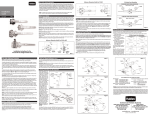
Step 1. To remove the purge cap, first
release the pressure from the unit by
slowly loosening the hose fitting from
the outlet port (check valve). Then
remove the two top retaining nuts with
an adjustable wrench. Next, pull the
cap off with a twisting, upward motion.
Seal
Washers
1. Stop engine when working under a vehicle. Always block the vehicle wheels
to prevent a fore or aft roll. Bleeding off system pressure may cause the
vehicle to roll. Keep hands away from brake chamber push rods and brake
adjusters; they may apply as system pressure drops.
Date Code
2. Never connect or disconnect a hose or line containing air pressure. It may
whip as air escapes. Never remove a component or a pipe plug unless you
are certain all system air pressure has been exhausted.
3. Never exceed recommended working air pressure and always wear safety
glasses when working with air pressure. Never look directly into component
ports or direct a pressurized air flow at anyone.
Step 1.
Step 2. Using an adjustable wrench
on the flats, unscrew the center shaft
by turning it counterclockwise. This
shaft has a heavy spring load and will
release as the shaft is unthreaded.
Remove the shaft from the purge
plate and lift the purge plate and
desiccant spring off the filter cartridge.
O-Ring
Seal
4. Never attempt to disassemble a component until you have read and
understood all recommended procedures. Some components contain
powerful springs and injury can result if not properly disassembled. Use only
proper tools and observe all precautions pertaining to the use of those tools.
Step 2.
Disassembly
When necessary, replacement of the purge valve in your Aerofiner II unit is easy.
In most cases, the Aerofiner II Air Dryer does not have to be removed from the
vehicle or equipment to replace the purge valve. The only tools necessary are an
adjustable wrench and a screwdriver. The RN970 Purge Valve Kit includes
replacement O-Rings, seals, valve and springs.
Prying
Groove
RN970 PURGE VALVE KIT CONTENTS
Item
1
2
3
4
5
6
7
8
9
10
11
12
Part No.
FF9276-19
22550-348
22550-341
22550-338
22550-334
N-11728-CW
22550-113
FF9860-05
FF9860-0402
FF9860-0401
FF9860-03
N-11728-HT
Qty.
1
1
1
1
1
1
1
1
1
1
2
1
Description
10 9
8
Seal, U-Cup (Purge Valve)
O-Ring - 4 3/4 (Housing)
O-Ring - 3 7/8 (Canister)
O-Ring - 3 1/2 (Purge Plate)
11
O-Ring - 3 (Purge Plate Check)
O-Ring - 1 1/2 (Shaft Assembly)
O-Ring - 3/4 (Purge Valve)
Valve
Spring - Small
3
Spring - Large
5
1
2
Seal Washer
O-Ring - 1 7/8 (Purge Valve/Housing) - Not Shown
Step 3.
4
6
7
Step 3. Remove the desiccant
canister from the Aerofiner II housing.
It may be necessary to loosen the
canister from the housing by prying
upward with a srewdriver inserted in
the canister outer slot (prying groove).
Then remove the center post, being
careful not to apply a sideload which
may bend the shaft.
Note: During reassembly, rotate the
canister while inserting and be sure
that the canister O-Ring (lubricate
prior to assembly) seats below the
housing shoulder.
Step 4. Turn the center post counterclockwise using a wrench. Do not use
a collapsible wrench such as a pipe
wrench or damage to the internal
thread port will occur. Loosen the
post several turns until it rotates
freely by hand.
Step 4.
DISASSEMBLY CONTINUED ON BACK SIDE


![Web Only [L31123W] Nov-2001](http://vs1.manualzilla.com/store/data/006261811_1-4af033c8ff7f86bb4ac91ee243d7e1f2-150x150.png)