1
Electronic key reader
Lector de llave electrónica
DS80DK50-001B LBT80086
DK500M-E
DK500M-E/B
3
4
ENGLISH
ESPANOL
WARNING: This document provides only some
essential product information.
Refer to the MP500 control panel manuals for more detailed
information.
GENERAL DESCRIPTION
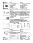
DK500M-E is a connecting device set for use with DK50 keys.
It comes in the following colours:
• DK500M-E: black front
• DK500M-E/B white front
The following adapters are available for domestic series:
• DKA/A - (KT2500111) 5 pieces for AVE® Sistema 45
• DKA/G - (KT2400111) 5 pieces for Gewiss® Playbus
• DKA/I - (KT2200111) 5 pieces for B-ticino® Light and International
• DKA/L - (KT2300111) 5 pieces for B-ticino® Living
For the use of readers in the series Vimar® Idea and Vimar®
8000 you must use the adapters available on the market:
Art. 16544 for Vimar® Idea and Art. 08324 for Vimar® 8000.
POSITIONING
ATENCIÓN: en este documento solo se citan algunas
indicaciones esenciales del producto.
Para más
información detallada, remitirse a los manuales de las
centrales MP500.
DESCRIPCIÓN GENERAL
El DK500M-E es un dispositivo de conexión preparado para el
uso de llaves DK50. Disponible en los sig. colores:
• DK500M-E: parte frontal negra
• DK500M-E/B: parte frontal blanca
Se encuentran disponibles los siguientes adaptadores para las
series civiles:
• DKA/A - (KT2500111) 5 piezas para AVE® Sistema 45
• DKA/G - (KT2400111) 5 piezas para Gewiss® Playbus
• DKA/I - (KT2200111) 5 piezas para B-ticino® Light e International
• DKA/L - (KT2300111) 5 piezas para B-ticino® Living
Para usar los lectores en las series Vimar® Idea y Vimar® 8000,
se deben utilizar los adaptadores existentes en el mercado:
Art. 16544 para Vimar® Idea y Art. 08324 para Vimar® 8000.
POSICIONAMIENTO
WARNING: In accordance with EN50131 standards, the
electronic key readers installed outside the protected zone must
be protected by devices to prevent tampering. EN50131
certification cannot be achieved if these devices are missing.
The Electronic key reader must be placed in an enclosed space
far from water and moisture sources.
CABLING
The Electronic key reader is connected to the bus MP500
control panel. The overall length of all the bus sections must not
exceed 400 m.
CONNECTING THE INPUTS
Connect the anti-tamper device to input 1 of the reader (yellow
wire: interrupt the wire by cutting it and connect the two pieces
to the anti-tamper device. The TAMPER is the factory setting.
ATENCIÓN: De acuerdo con las normas EN50131, los
lectores montados en el exterior de la zona protegida se deben
proteger mediante dispositivos antisabotaje (tamper); la falta de
los mismos provoca la pérdida de la certificación EN50131.
El lector de llave electrónica debe estar ubicado en un
ambiente resguardado y protegido del agua y la humedad.
CABLEADO
El lector de llave se debe conectar en el bus de la central
MP500. La longitud global de todos los tramos del bus no debe
superar los 400 metros.
CONEXIÓN ENTRADAS
Conectar el tamper a la entrada 1 del lector (cable amarillo:
interrumpir el cable, cortándolo y conectar los dos fragmentos
al tamper). La entrada viene de fábrica ya programada como
WARNING: “Double balance” is the only EN50131 SABOTAJE.
compliant connection mode. Refer to the manuals of MP500
units for further, more detailed information.
ATENCIÓN: El único modo de conexión de conformidad
con la norma EN50131 es la de “Doble Balanceado”. Para más
DOUBLE
SINGLE
NC
información detallada consultar los manuales de las centralitas
BALACING
BALACING
MP500.
READER
READER
READER
NC
LECTOR
MONO
BALANCEADO
LECTOR
DOBLE
BALANCEADO
LECTOR
5
6
ELKRON
TEL. +39.011.3986711 – FAX +39.011.3986703
www.elkron.com – mail to: [email protected]
ELKRON is a trademark of URMET S.p.A.
ELKRON es una marca registrada de URMET S.p.A
Bologna, 188/C - 10154 Torino (TO) – Italy
www.urmet.com
EN50131
ACQUISITION
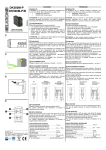
The reader can be acquired by pressing the dedicate button
(Fig.5) following the instructions inside the control panel
installation manual.
To display the reader address, press the button and count the
blink of the lateral yellow LED.
FRONT VIEW
The device features four green LEDs (A-B-C-D) used to indicate
the status of the controller sectors, plus one red LED (E) used
to indicate system information and reading key.
“F” corresponds to the insertion hole for the key.
USE
Total Arming and disarming
Insert the key and remove it when the red LED E blinks.
The 4 green LED (A-B-C-D) indicate the status of the controlled
sectors: LED ON indicate an armed sector.
If a LED is associated to more sectors, when they are not all
armed the LED blinks.
The possibility of activation of each sector depends on the
programming of the reader and the key used.
Partial arming
Insert the key; after a while the reader shows the possible
combinations of partialisation starting with the last made.
To confirm the choice remove the key.
The LEDs indicate the armed sectors.
NOTE: If you use a key is not acquired (key not recognized),
the 4 green LED will blink rapidly.
TECHNICAL CHARACTERISTICS
Rated supply voltage ........................................... 13,8 Vdc
(picked by the control panel through the bus)
Operating voltage min/max .................................. 9 Vdc ÷ 15 Vdc
Rated current absorption at 12V:
LEDs OFF............................................................ 6 mA
All LEDs ON......................................................... 56 mA
EN50131
ADQUISICIÓN
Adquirir el lector presionando el botón correspondiente (Fig.5)
siguiendo las instrucciones presentes en el manual de instalación
de la central. Para visualizar el número del lector, presionar el
botón y contar el número de parpadeos del LED amarillo lateral.
VISTA FRONTAL
El dispositivo presenta 4 LED de color verde (A-B-C-D), utilizados
para indicar el estado de los sectores controlados, y 1 LED de
color rojo (E) para indicar señalizaciones del sistema y llave
presente. “F” corresponde al agujero de la inserción de la llave.
USO
Activación y desactivación total
Introducir la llave y extraerla cuando el LED rojo E parpadea.
Los 4 LED de color verde (A-B-C-D) indican el estado de los
sensores controlados: LED encendido corresponde a sector
activado. Si a un LED se asocian varios sectores, cuando no están
todos activados, el LED parpadea. La posibilidad de activación de
cada sector depende de la programación del lector y de la llave
utilizada.
Activación parcial
Inserte la llave; después de algunos instantes, el lector presenta
las posibles combinaciones de parcialización iniciando por la
última realizada.
Para confirmar la elección, extraer la llave: se encienden los
LED de los sectores activados.
NOTA: Si se usa una llave no adquirida (llave no reconocida),
parpadean rápidamente los 4 LED verdes.
CARACTERÍSTICAS TÉCNICAS
Tensión nominal de alimentación......................... 13,8 Vcc
(tomados de la central mediante bus)
Tensión de funcionamiento mín./máx .................. 9 Vcc ÷ 15 Vcc
Corriente nominal absorbida a 12V:
LED apagados ..................................................... 6 mA
LED encendidos (todos) ...................................... 56 mA