1
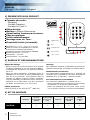
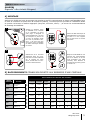
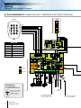
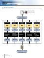
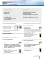
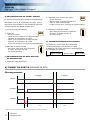
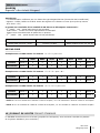
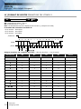
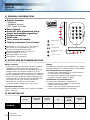
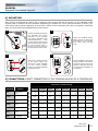
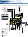
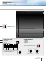
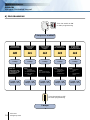
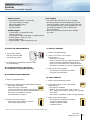
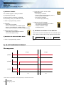
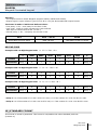
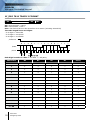
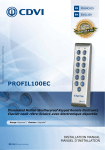
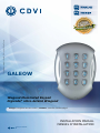
* Voir conditions de garantie à vie limitée. / Refer to Limited Lifetime Warranty.
FR
FRANCAIS
EN
ENGLISH
GALEOW
Wiegand Illuminated Keypad
Digicode® rétro-éclairé Wiegand
Range: Integrated access control / Gamme: Contrôle d’accès intégré
INSTALLATION MANUAL
MANUEL D’INSTALLATION
Group Products
MANUEL D’INSTALLATION
GALEOW
Digicode® rétro-éclairé Wiegand
1] PRESENTATION DU PRODUIT
Formats de sortie :
- Wiegand,
- Format Standard,
- Format Iso Track 2.
Rétro-éclairé.
Matière : Alliage d’aluminium.
Signalisation lumineuse et sonore.
Pose en applique.
Faible encombrement.
Montage avec vis Torx®.
Etanchéité totale (surmoulé).
TANCE
HAUTE RESIS
ISME
AU VANDAL
DEEE & RoHS
IP64
Dimensions (L x l x P) : 110 x 75 x 15 mm.
Switch à l’arrière du GALEOW pour l’entrée
et la sortie du mode programmation.
Sauvegarde mémoire permanente E2PROM.
Nombre de termes : 4, 5 ou 6.
Alimentation : 12 V DC.
Consommation : 100 mA max.
Certification CE
Test vibrations
-25°C à +70°C
2] RAPPELS ET RECOMMANDATIONS
Rappel de câblage
- Dans le cas d’une connexion directe à la centrale
CT-V900-A (CENTAUR) ou une des centrales LINKNET,
le GALEOW doit être placé à une distance maximale
de 50 m.
- Dans les autres situations, la distance entre le
GALEOW et le contrôleur de porte (INTBUSW) doit
être de 50 m maximum. et la distance entre la
centrale ou platine jusqu’au dernier contrôleur
de porte (INTBUSW) peut atteindre 1200 m maximum.
- Attention de ne pas passer vos fils à proximité
de câbles «Courant fort» (ex: 230 V AC).
Câbles préconisés
Câbles 2 paires (4 fils) SYT1 8/10ème (AWG 20).
Montage
Afin d’optimiser la fixation du GALEOW et de prévenir les
tentatives d’arrachage, privilégiez les surfaces planes.
Alimentations préconisées
Une alimentation indépendante de la centrale est
nécessaire pour le GALEOW. Il existe deux alimentations
adaptées pour ce Digicode® : ARD12 ou BS60
Recommandations d’installation
Pour sécuriser l’installation, n’oubliez pas de :
- placer la varistance sur le système de verrouillage,
en parallèle, au niveau de l’alimentation.
- placer une résistance de 120 ohms, entre A et B,
sur le dernier contrôleur de porte du BUS RS485.
3] KIT DE MONTAGE
GALEOW
2
cdvi.com
cdvigroup.com
Varistance
Vis Torx®
à tête fraisée
(M4x10)
Clé mâle coudée
pour vis Torx®
(T20)
Cache vis
Vis cruciforme
à tête fraisée
M4x30
Cheville
plastique
S5
1
1
1
2
2
2
MANUEL D’INSTALLATION
GALEOW
Digicode® rétro-éclairé Wiegand
4] MONTAGE
Après avoir vérifié que le kit de montage est complet et opéré le raccordement du clavier codé GALEOW (avec
ou sans le contrôleur de porte selon la centrale ou platine), vous allez pouvoir procéder à l’installation finale
du produit. Réunissez le matériel approprié (Perçeuse, tournevis, mètre,...) et suivez les recommandations
de montage du GALEOW :
1
3
Vérifiez la distance entre
le GALEOW et la centrale
ou le contrôleur de porte
(Voir page 3 «Rappels et
recommandations»). Prenez
les marques et percez les
2 trous de fixation (forêt
Ø 5 mm et profondeur minimum. = 35 mm) ainsi que
l’ouverture pour le passage
du câble électrique destiné
au clavier.
Passez le câble électrique du
GALEOW dans son ouverture
et fixez le à son support
par le haut avec le crochet
supérieur.
2
4
Positionnez les 2 chevilles
plastiques dans les trous.
Puis Fixez le fond du GALEOW
sur le support de votre
choix, à l’aide des vis cruciformes à têtes fraisées.
Bloquez le GALEOW sur son
support par l’intermédiaire
de la vis TORX® et de son
outil spécifique (clé mâle
coudée). Pour finaliser le
montage de ce produit, placez
le cache-vis.
5] RACCORDEMENTS CONNEXION DIRECTE AUX BORNIERS D’UNE CENTRALE
Raccordement aux bornier des centrales
Câbles
GALEOW
Sorties
CT-V900-A
LT20PB
LT20PBIP
LT20AC
LT20IP
ROUGE
Alimentation
12 V DC
+12V
12VDC
12VDC
NOIR
Alimentation
12 V DC
R2/0V
0V
0V
MARRON
Commande
extérieur du buzzer
VERT
DATA 0
R2/D0
CL
CL
BLANC
DATA 1
R2/D1
DA
DA
BLEU
CLOCK
GRIS
COMMUN 0V
UCA3
PROMI1000
PROMI1000PC
PROMI500
DGPROX
DG502
6 et 10
1
1
1
1 et 6
5 et 9
M
M
M
4
OUT5/6
cdvi.com
cdvigroup.com
3
MANUEL D’INSTALLATION
GALEOW
Digicode® rétro-éclairé Wiegand
6] RACCORDEMENTS CONNEXION AVEC CONTRÔLEUR DE PORTE (INTBUSW)
GALEOW
Blanc
vert
Bleu
Rouge
Noir
Gris
GALEOW
ROUGE
Alimentation 12 V DC
NOIR
0V
BLEU
Clock
VERT
Data 0
BLANC
Data 1
MARRON
Buzzer
GRIS
INTBUSW
Commun 0V
Gâche
Ventouse
Varistance
Alimentation
Pour l’alimentation,
il y a deux modes possibles :
Câble
blindage
12 V DC uniquement
(Configuration usine)
Coupez le strap
12 V AC ou 24 V DC
4
cdvi.com
cdvigroup.com
Si vous ne souhaitez
pas de gestion de l’etat
porte : Relier E et M
Vers d’autres contrôleur
de portes (INTBUSW)
MANUEL D’INSTALLATION
GALEOW
Digicode® rétro-éclairé Wiegand
INTBUSW (Contrôleur de porte)
Bornier 5 points : Carte mère
V
Alimentation -
12
Alimentation +
1
Data O
2
Clock
3
Data 1
Bornier 16 points : Carte mère
R
Contact N.F porte Ventouse (+)
C
Contact commun + Alimentation
T
Contact N.O porte Gâche
R
Contact N.F alarme
C
Contact commun
T
Contact N.O alarme
+ ~ - Alimentation DC ou AC 12 V ou 24 V DC
Sans cavalier : sans clock
Avec cavalier : avec clock
P1
Bouton poussoir intérieur
M
Masse commune ( P1 et P2 )
P2
Bouton poussoir extérieur
E
Contact fermeture porte, N.F. (Porte fermée) et N.O. (Porte ouverte)
L
Contact autorisation lecture du badge (N.O) autorisée et (N.F) interdite
M
Masse commune ( E et M ) ou (E et L)
A
Bus RS485 (tous les A doivent être reliés entre eux sous la forme d’une chaîne)
B
Bus RS485 (tous les B doivent être reliés entre eux sous la forme d’une chaîne)
Bornier 3 points : Carte fille
7
Signalisation > couleur rouge
8
Signalisation > couleur verte
9
Buzzer
MODE AUTONOME
MODE CENTRALISÉ
TELACCESS
-
- Programmation de l’adresse par dipswitch
- Dip4 = ON
Adressage DIPSWITCH
1
2
3
4
Mode
ON
ON
ON
ON
Façade
OFF
ON
ON
ON
Lecteur 1
ON
OFF
ON
ON
Lecteur 2
OFF
OFF
ON
ON
Lecteur 3
ON
ON
OFF
ON
Lecteur 4
TERENA,
UGM-UGL,
UGP/40
PDN345BUSPROX
- Programmation de l’adresse par installation
- Dip4 = OFF
ST1 (Cavalier de programmation)
ST1 (Cavalier de programmation) : Normal
Normal (Config. usine)
Installation
cdvi.com
cdvigroup.com
5
MANUEL D’INSTALLATION
GALEOW
Digicode® rétro-éclairé Wiegand
8] PROGRAMMATION
Basculez le switch
sur ON pour entrer
en programmation
2 bips sonores
Programmation
de l’éclairage
Programmation
du format
de sortie
Programmation
du nombre
de termes
Programmation
du signal sonore
Programmation
du mode décimal
ou héxadécimal
A0
A1
A2
A3
A4
1 bips
1 bips
1 bips
1 bips
1 bips
Tapez :
- 1 = Wiegand
26 bits
- 2 = Format Standard
- 3 = Format ISO
Track 2
Tapez 4, 5 ou 6
pour définir le
nombre de termes
Tapez :
- 0 = suppression
du bip des touches
- 1 = Autorisation
du bip des touches
Tapez :
- 0 = mode décimal
- 1 = mode
hexadécimal
1 bips = OK
4 bips = Erreur
1 bips = OK
4 bips = Erreur
1 bips = OK
4 bips = Erreur
1 bips = OK
4 bips = Erreur
Tapez la durée
de commande en
secondes ou “OO”
pour un éclairage
permanent
1 bips = OK
4 bips = Erreur
2 bips sonores
6
cdvi.com
cdvigroup.com
MANUEL D’INSTALLATION
GALEOW
Digicode® rétro-éclairé Wiegand
Valeurs par défaut
- Tempo éclairage : 10 s.
- Nombre de termes : 5.
- Sortie Wiegand 26 bits.
- Buzzer inactif.
- Mode décimal.
Correspondance des signaux sonores
- 1 bip court > Mise sous tension et bip touche.
- 1 bip long > Validation d’une saisie
en programmation.
- 2 bips courts > Entrée et sortie
de programmation.
- 4 bips courts > Erreur de saisie.
A] ENTRÉE EN PROGRAMMATION
C] PROGRAMMATION DU FORMAT DE SORTIE
1. Entrez en programmation*.
1. Coupez l’alimentation.
Basculez le switch sur ON.
Rétablir l’alimentation.
A1
2. Deux bips sont émis pour confirmer l’entrée
en programmation.
La commande extérieure du buzzer ne fonctionne
pas en programmation.
B] PROGRAMMATION DE L’ÉCLAIRAGE
2. Tapez A1 pour choisir
le format de sortie :
- Un bip est émis.
- Tapez 1 pour une sortie au format Wiegand 26 bits.
- Tapez 2 pour une sortie au format Standard.
- Tapez 3 pour une sortie au format ISO Track 2.
- Un bip de validation est émis.
3. Basculez le switch sur OFF :
- Deux bips sont émis pour confirmer
le retour au mode normal
de fonctionnement.
D] PROGRAMMATION DU NOMBRE DE TERMES
1. Entrez en programmation*.
1. Entrez en programmation*.
2. Tapez A0 pour la temporisation
d’éclairage du clavier :
- Un bip est émis.
- Tapez la durée de commande en secondes
(10 pour 10 secondes à 99 pour 99 secondes)
ou tapez 00 pour obtenir un éclairage permanent.
- Un bip de validation est émis.
A0
3. Basculez le switch sur OFF :
- Deux bips sont émis pour confirmer
le retour au mode normal
de fonctionnement.
Termes utilisés
- Les codes utilisateurs doivent être composés
de 4,5 ou 6 termes.
- En mode décimal, seuls la touche B est
interdite pour composer les codes.
Touche B pour valider.
- En mode hexadécimal, seuls les touches
de 0 à 9 sont autorisées pour composer
les codes. Touche B pour valider.
- L’utilisateur doit composer son code
puis appuyer sur la touche B pour valider.
2. Tapez A2 pour la saisie du nombre
de termes des codes :
- Un bip est émis.
- Tapez 4,5 ou 6 pour le nombre de termes.
- Un bip est émis pour confirmer
la programmation.
A2
3. Basculez le switch sur OFF :
- Deux bips sont émis pour confirmer
le retour au mode normal
de fonctionnement.
* Référez-vous à la procédure d’entrée en programmation en début de chapitre.
cdvi.com
cdvigroup.com
7
MANUEL D’INSTALLATION
GALEOW
Digicode® rétro-éclairé Wiegand
E] PROGRAMMATION DU SIGNAL SONORE
Le signal sonore est toujours audible en programmation.
Par défaut, lors de la composition du code, aucun
bip touche n’est audible. Il est possible d’autoriser
les bips touches en faisant comme suit :
1. Entrez en programmation*.
A3
2. Tapez A3 :
- Un bip est émis.
- Tapez 0 pour supprimer les bips touches
pendant la composition du code.
- Tapez 1 pour autoriser les bips touches
pendant la composition du code.
- Un bip est émis pour confirmer la programmation.
3. Basculez le switch sur OFF :
- Deux bips sont émis pour confirmer
le retour au mode normal
de fonctionnement.
A4
2. Tapez A4 pour la saisie du mode :
- Un bip est émis.
- Tapez 0 pour le mode décimal ou 1
pour le mode hexadécimal.
- Un bip est émis pour confirmer la programmation.
3. Basculez le switch sur OFF :
- Deux bips sont émis pour confirmer
le retour au mode normal de
fonctionnement.
G] COMMANDE EXTÉRIEURE DU BUZZER
Le buzzer du clavier peut être commandé
extérieurement par une centrale. Il suffit
d’appliquer un signal logique sur l’entrée Buzzer
du GALEOW (Fil marron).
Buzzer inactif
F] PROGRAMMATION DU MODE DÉCIMAL
OU HEXADÉCIMAL
Buzzer actif
OV
1. Entrez en programmation*.
9] FORMAT DE SORTIE WIEGAND 26 BITS
Chronogrammes
0 logique
1 logique
\DATA1
\CLOCK
\DATA0
50 μs
2ms
* Référez-vous à la procédure d’entrée en programmation en début de chapitre.
8
cdvi.com
cdvigroup.com
50 μs
2ms
Buzzer inactif
MANUEL D’INSTALLATION
GALEOW
Digicode® rétro-éclairé Wiegand
Interfaçage
- La communication s’effectue par une liaison de type Wiegand 26 bits (Format 26 bits hexadécimal).
- Signaux : DATA1, DATA0 et CLOCK. Sortie des signaux en collecteur ouvert (avec pulls up interne
de 2.2K au +5V)
La trame est constituée d’une totalité de 26 bits et se décompose comme suit :
- 1ère parité : 1 bit – parité paire des 12 bits suivants.
Code clavier : 3 mots d’un octet représentant le code tapé.
Chaque mot est transmis bit de poids fort en premier.
- 2ème parité : 1 bit – parité impaire des 12 bits précédents.
Bit 1
Bit 2 … bit 25
Bit 26
Parité paire sur bit 2… bit13
Donnée (24 bits)
Parité impaire sur bit 14… bit 25
KEYPAD CODE
Exemple avec un code clavier à 4 termes: « 1 3 7 5 » puis « B »
1
0000
0000
0001
0011
0111
0101
0
Décimal
Parité 1
0
0
1
3
7
5
Parité 2
Hexadécimal
Parité 1
0
0
0
5
5
F
Parité 2
Exemple avec un code clavier à 5 termes: « 7 1 3 7 5 » puis « B »
Décimal
Parité 1
0
7
1
3
7
5
Parité 2
Hexadécimal
Parité 1
0
1
1
6
C
F
Parité 2
Exemple avec un code clavier à 6 termes: « 6 7 1 3 7 5 » puis « B »
Décimal
Parité 1
6
7
1
3
7
5
Parité 2
Hexadécimal
Parité 1
0
A
3
E
8
F
Parité 2
- Parité 1 : «0» si le nombre de 1 dans bit 2 à bit 13 est paire, «1» si le nombre de 1 dans bit 2 à bit 13 est impaire.
- Parité 2 : «0» si le nombre de 1 dans bit 14 à bit 25 est impaire, «1» si le nombre de 1 dans bit 14 à bit 25 est paire.
10] FORMAT DE SORTIE FORMAT STANDARD
Le GALEOW fonctionne sous ce format (propriété de l’entreprise) avec certaines centrales ou platines
de la gamme Standard (nous consulter).
cdvi.com
cdvigroup.com
9
MANUEL D’INSTALLATION
GALEOW
Digicode® rétro-éclairé Wiegand
11] FORMAT DE SORTIE FORMAT ISO 7811 TRACK 2
SS
Caractères
ES
LRC
SS : Sentinelle de début > Hex B
ES : Sentinelle de fin > Hex F
LRC : Ou Exclusif de tous les caractères de la trame (y compris SS et ES)
Le nombre de caractères est fixé à 8 :
- En 4 termes – 00001234
- En 5 termes – 00012345
- En 6 termes - 00123456
/Présence
/Data
/Clock
Chaque caractère est composé de 5 bits : 4 bits de données + 1 bit de parité.
Caractères
10
B4
B3
B2
B1
Parité
0
0
0
0
0
1
1
0
0
0
1
0
2
0
0
1
0
0
3
0
0
1
1
1
4
0
1
0
0
0
5
0
1
0
1
1
6
0
1
1
0
1
7
0
1
1
1
0
8
1
0
0
0
0
9
1
0
0
1
1
A
1
0
1
0
1
B = SS
1
0
1
1
0
C
1
1
0
0
1
D = FD
1
1
0
1
0
E
1
1
1
0
0
F = ES
1
1
1
1
1
cdvi.com
cdvigroup.com
MANUEL D’INSTALLATION
GALEOW
Digicode® rétro-éclairé Wiegand
8] CONDITIONS DE GARANTIE À VIE LIMITÉE [EXTRAIT]*
Les sociétés CDVI garantissent que ce produit est dépourvu de tout vice caché, tant dans les matériaux
que dans sa fabrication, à la condition, qu’il soit installé conformément aux préconisations du fabricant
et qu’il n’y ait pas eu d’interventions ou de modifications sur le produit. La responsabilité de CDVI se limite
à la réparation ou à l’échange du produit. CDVI n’assume aucune responsabilité concernant les dommages
sur les biens ou les personnes. Un produit reconnu défectueux par CDVI doit être retourné au serviceaprès-vente de CDVI, après l’obtention du numéro d’autorisation de Retour de Produit(s) Défectueux (RMA).
La responsabilité de CDVI se limite à la réparation ou au remplacement d’un produit ou pièces défectueuses,
en ses ateliers. L’une ou l’autre de ces interventions sont définis par le service-après-vente de CDVI.
Le préjudice imputable à CDVI ne saurait en aucun cas dépasser la valeur du produit. La responsabilité
de CDVI ne peut être engagée auprès de l’acheteur, installateur, client final ou qui que ce soit, lors de dommages
consécutifs à des imperfections ou mauvais fonctionnement du produit. Cette garantie prend effet
à la date d’enregistrement du produit auprès de CDVI, à partir de l’instant ou la date d’enregistrement est
dûment complétée, dans la limite d’un mois, après la date de livraison au client final. Pour obtenir les détails complets de cette garantie et enregistrer votre/vos produit(s) pour bénéficier de cette « Garantie à Vie
limitée ». Veuillez compléter la carte d’enregistrement présente dans la boite du produit et nous la retourner,
par email ou par courrier, à l’adresse de l’entité CDVI la plus proche ou vous enregistrer en ligne à l’adresse
www.cdvigroup.com. Les contacts des entités CDVI sont accessibles en ligne à l’adresse www.cdvigroup.com
ou au dos de la notice d’installation.
EXCLUSIONS DE LA GARANTIE : A l’EXCEPTION DES POINTS EVOQUES PRECEDEMMENT, CDVI N’APPLIQUE
AUCUNE GARANTIE, NI DELIBEREE NI TACITE, A TOUS LES PROBLEMES INCLUANT LE CONDITIONNEMENT,
LE TRANSPORT, LEUR COMMERCIALISATION OU LES CONDITIONS D’UTILISATIONS PARTICULIÈRES.
12] NOTES
*Voir conditions de garantie à vie limitée
cdvi.com
cdvigroup.com
11
INSTALLATION MANUAL
GALEOW
Wiegand illuminated keypad
1] GENERAL INFORMATION
Output formats:
- Wiegand,
- Standard format,
- ISO Track 2 format.
Back-lighted.
Material: Cast aluminium alloy.
Visual and audible signalling.
Surface mounting.
Small size.
Torx® screw assembly.
Totally waterproof (cast body).
TANCE
HIGH RESIS
ISM
TO VANDAL
WEEE & RoHS
IP64
Dimensions (L x W x D): 110 x 75 x 15 mm.
Rear switch on the GALEOW for entry to
and exit from programming mode.
Permanent E2PROM memory back-up.
Number of digits: 4, 5 or 6.
Operating voltage: 12 V DC.
Consumption: 100 mA max.
CE Certification
Envrionmental tests:
vibrations
-25°C to +70°C
2] NOTES AND RECOMMENDATIONS
Wiring reminder
- In the case of direct connection to the CT-V900-A
(CENTAUR) central controller or one of the
LINKNET door controllers, the GALEOW must be
installed within a maximum distance of 50 m.
- In other cases, the distance between the GALEOW
and the (INTBUSW) door controller must be within a
maximum of 50 m and the distance between the
central controller or panel and the last (INTBUSW door
controller may be up to 1200 m maximum.
- Take care not to pass your wires close
to «High voltage» cables (e.g.: 230 V AC).
Recommended cables
2 pairs of cables (4 strand) SYT1 8/10ths (Shielded
cables - AWG 20).
Fitting
To optimise the mounting of the GALEOW and to combat
attempted tampering, it should be fitted on a flat surface.
Recommended power supplies
- A power supply independent of the central controller
is necessary for the GALEOW.
- There are two suitable power supplies for this
Digicode® keypad: ARD12 or BS60
Installation recommendations
To protect the installation, remember to:
- install the varistor in parallel on the locking
system power supply side,
- install a 120 ohm resistor between A and B
on the last BUS RS485 door controller.
3] MOUNTING KIT
GALEOW
12
cdvi.com
cdvigroup.com
Varistor
Torx® screw
(M4x10)
T20 Torx®
spanner
Cap
mounting
screw
(M4x30)
S5 plastic
anchor
1
1
1
2
2
2
INSTALLATION MANUAL
GALEOW
Wiegand illuminated keypad
4] MOUNTING
After having verified that the fitting kit is complete and having made the connection of the GALEOW coded
keypad (with or without the door controller depending on whether you use a central controller or panel), you
can proceed with the final installation of the product. Collect up the necessary tools (drill, screwdriver, measuring
tape, etc) and follow the GALEOW fitting instructions:
1
3
Confirm the distance between
the GALEOW and central
controller or door controller
(see page 3 «Reminders and
recommendations»).
Mark
out the locations and drill two
mounting holes (Ø 5 mm drill
bit and minimum depth =
35 mm) as well as the hole
for the keypad’s electric cable.
Insert the GALEOW electric
cable through its cable hole
and attach it to its support
from above with the top
hook.
2
4
Insert the 2 plastic anchors
in the holes. Mount the
back plate of the GALEOW
on your chosen support
using the supplied (M4x30)
mounting screws.
Fix the GALEOW on its support
using the TORX® screw and its
special tool (elbow male screw
spanner). Apply the screw cap
to complete the installation of
this product.
5] CONNECTIONS: DIRECT CONNECTION TO THE TERMINAL BLOCKS OF A CONTROLLER
Controller terminal wirings
GALEOW
Outputs
CT-V900-A
LT20PB
LT20PBIP
LT20AC
LT20IP
RED
Input voltage
12VDC
+12V
12VDC
12VDC
BLACK
0V
R2/0V
0V
0V
BROWN
Buzzer command
input
GREEN
DATA 0
R2/D0
CL
CL
WHITE
DATA 1
R2/D1
DA
DA
BLUE
CLOCK
GREY
0V COMMON
UCA3
PROMI1000
PROMI1000PC
PROMI500
DGPROX
DG502
6 and 10
1
1
1
1 and 6
5 and 9
M
M
M
4
OUT5/6
cdvi.com
cdvigroup.com
13
INSTALLATION MANUAL
GALEOW
Wiegand illuminated keypad
6] CONNECTIONS: CONNECTION WITH THE (INTBUSW) DOOR CONTROLLER
GALEOW
White
Green
Blue
Red
Black
Grey
GALEOW
RED
12VDC
BLACK
BLUE
0V
Clock
GREEN
Data 0
WHITE
Data 1
BROWN
Buzzer
GREY
INTBUSW
0V commun
Strike
Magnet
Varistor
Power supply
Two different configurations,
are possible:
Shielded
cable
12VDC only
(As standard)
Cut the strap
12VAC or 24VDC
Door contact (not used)
Connect E and M
14
cdvi.com
cdvigroup.com
To other door controllers
(INTBUSW)
INSTALLATION MANUAL
GALEOW
Wiegand illuminated keypad
INTBUSW (Door controller)
Terminal block : Motherboard
V
Input voltage -
12
Input voltage +
1
Data O
2
Clock
3
Data 1
Terminal block : Motherboard
R
N/C contact eletromagnetic lock (+)
C
Common contact power supply (+)
T
N/O contact electric release
R
N/C contact alarm
C
Common
T
N/O contact alarm
+ ~ - Input voltage DC or AC, 12V or 24V
Without jumper : without clock
With jumper : with clock
P1
Request-to-enter input
M
Common ( P1 et P2 )
P2
Request-to-enter input
E
Door contact, N/C (Door closed) and N/O (Door open)
L
Reader activation imput (N/O) reader enabled and (N/C) reader disabled
M
Common ( E and M ) or (E and L)
A
RS485 Bus (All the A must be connected together in daisy chain)
B
RS485 Bus (All the B must be connected together in daisy chain)
Terminal block - 3 points : Piggyback board
7
LED > Red color
8
LED > Green color
9
Buzzer
STAND ALONE MODE
CENTRALIZED MODE
TELACCESS
-
- Dipswitch address set up
- Dip4 = ON
DIP SWITCH adressing
1
2
3
4
Mode
ON
ON
ON
ON
Front plate
OFF
ON
ON
ON
Reader 1
ON
OFF
ON
ON
Reader 2
OFF
OFF
ON
ON
Reader 3
ON
ON
OFF
ON
Reader 4
TERENA,
UGM-UGL,
UGP/40
PDN345BUSPROX
- Address programming during installation
- Dip4 = OFF
ST1 (Programming jumper)
ST1 (Programming jumper) : Normal
Normal (As standard)
Installation
cdvi.com
cdvigroup.com
15
INSTALLATION MANUAL
GALEOW
Wiegand illuminated keypad
8] PROGRAMMING
Turn the switch to ON
to start programming
2 beeps are emitted
Programming
the illumination
Programming
the output
format
Programming
the number
of digits
Programming
the audible signal
Programming
for decimal or
hexadecimal mode
A0
A1
A2
A3
A4
1 beep
1 beep
1 beep
1 beep
1 beep
Enter the
illumination time
in seconds or “00”
for a permanent
illumination.
Enter:
- 1 = Wiegand
26-bit format
- 2 = Standard format
- 3 = ISO Track 2
format
Enter:
4, 5 or 6 to specify
the number of digits.
1 beep = OK
4 beeps = Error
1 beep = OK
4 beeps = Error
1 beep = OK
4 beeps = Error
Enter:
- 0 = disable the
keypad beeps
- 1 = Enable the
keypad beeps
1 beep = OK
4 beeps = Error
Turn the switch to OFF
to finish programming
2 beeps
16
cdvi.com
cdvigroup.com
Enter:
- 0 = for decimal
mode
- 1 = for
hexadecimal
mode
1 beep = OK
4 beeps = Error
INSTALLATION MANUAL
GALEOW
Wiegand illuminated keypad
Default values
- Illumination duration: 10 seconds,
User code lenght: 5 digits,
26 bit wiegand output,
Buzzer disabled,
Decimal mode.
Audible Signal
- 1 short beep > keypad powered
and key presses,
- 1 long beep > data computing in programming,
- 2 short beeps > Entry or Exit
from programming,
- 4 short beeps > data computing error.
A] ENTRY IN PROGRAMMING
Code Length
- The user code must be in 4, 5 or 6 digits,
- In decimal mode, all the keypad keys can be
used to program a user code except the B key,
- In hexadecimal mode, all the keypad keys can
be used to program a user code except
the A and B key,
- Enter the user code and then B to validate
the code.
C] OUTPUT FORMAT
1. Enter in programming*.
1. Turn off the power.
Put the switch to ON.
Put back the power.
2. Press A1 to enter in the output
format menu :
- One beep is emitted.
- Press 1 to select 26-bit wiegand output format
- Press 2 to select Standard output format
- Press 3 to select ISO Track 2 output format
- One beep is emitted to confirm programming.
A1
2. Two beeps are emitted to confirm entry
in programming.
The command control of the buzzer
is not possible in programming mode.
3. Remove the ST1 jumper:
- Two beeps are emitted to confirm
exit from programming.
B] ILLUMINATION DURATION
D] CODE LENGTH
1. Enter in programming*.
1. Enter in programming mode*.
A2
2. Enter A0 to program the illumination duration :
- One beep is emitted.
- Enter the time in seconds,
10 for 10 seconds to 99 for 99 seconds
or enter 00 for a permanent illumination.
- One beep is emitted to confirm
the illumination duration.
2. Press A2 to enter in the code length
setting menu:
- One beep is emitted.
- Press 4 for a 4-digit user code, press 5
for a 5-digit user code or press 6 for a 6-digit
user code.
- One beep is emitted to confirm programming.
3. Remove the ST1 jumper :
- Two beeps are emitted to confirm
exit from programming.
3. Remove the ST1 jumper:
- Two beeps are emitted to confirm
exit from programming.
- 4 beeps indicate a data
computing error.
A0
* Please refer to the procedure to start programming at the start of this section
cdvi.com
cdvigroup.com
17
INSTALLATION MANUAL
GALEOW
Wiegand illuminated keypad
E] AUDIBLE SIGNAL
2. Press A4 to enter in the mode
setting menu:
- One beep is emitted.
- Press 0 for a decimal mode, press 1
for a hexadecimal mode.
- One beep is emitted
to confirm programming
The audible signal is always enabled
in programming mode.
In factory default, the buzzer is disabled
when pressing a key. To enable the buzzer:
1. Enter in programming mode*.
2. Press A3:
- One beep is emitted.
- Press 0 to disable the audible signal.
- Press 1 to enable the audible signal.
- One beep is emitted to confirm programming.
A3
3. Remove the ST1 jumper:
- Two beeps are emitted to confirm
exit from programming.
3. Remove the ST1 jumper:
- Two beeps are emitted to confirm
exit from programming.
- 4 beeps indicate a data
computing error.
G] EXTERNAL CONTROL OF THE BUZZER
The buzzer can be activated from an external input.
The control is done with a logic signal on the input.
F] DECIMAL OR HEXADECIMAL MODE
Buzzer OFF
1. Enter in programming mode*.
Buzzer ON
OV
9] 26-BIT WIEGAND FORMAT
Chronograms
0 logic
1 logic
\DATA1
\CLOCK
\DATA0
50 μs
2ms
* Please refer to the procedure to start programming at the start of this section
18
cdvi.com
cdvigroup.com
A4
50 μs
2ms
Buzzer OFF
INSTALLATION MANUAL
GALEOW
Wiegand illuminated keypad
Interface
- The output format is 26-bit Wiegand (Signals: DATA1, DATA0 and CLOCK),
- Output signal in open collectors (pull up of 2.2K in +5V) 26-bit hexadecimal output format.
The frame is made of 26-bit and built as follow:
- First parity: 1-bit – even parity for the first 12-bit,
- User Code: 3 half of a byte represent the code entered.
Each byte is transferred from bit 7 to bit 0,
- Second parity: 1-bit – odd parity for the last 12-bit.
Bit 1
Bit 2 … bit 25
Bit 26
Even parity on bit 2…bit13
Data (24 bits)
Odd parity on bit 14…bit 25
KEYPAD CODE
Example with a 4-Digit keypad code: « 1 3 7 5 » Then « B »
1
0000
0000
0001
0011
0111
0101
0
Decimal
Parity 1
0
0
1
3
7
5
Parity 2
Hexadecimal
Parity 1
0
0
0
5
5
F
Parity 2
Example with a 5-Digit keypad code: « 7 1 3 7 5 » Then « B »
Decimal
Parity 1
0
7
1
3
7
5
Parity 2
Hexadecimal
Parity 1
0
1
1
6
C
F
Parity 2
Example with a 6-Digit keypad code: « 6 7 1 3 7 5 » Then « B »
Decimal
Parity 1
6
7
1
3
7
5
Parity 2
Hexadecimal
Parity 1
0
A
3
E
8
F
Parity 2
- Parity 1: «0» if the number of 1 in bit 2 to bit 13 is even, «1» if the number of 1 in bit 2 to bit 13 is odd.
- Parity 2: «0» if the number of 1 in bit 14 to bit 25 is odd, «1» if the number of 1 in bit 14 to bit 25 is even.
10] STANDARD FORMAT
This format is owned by Standard. This format is compatible with other Standard products.
(Contact us)
cdvi.com
cdvigroup.com
19
INSTALLATION MANUAL
GALEOW
Wiegand illuminated keypad
11] ISO 7811 TRACK 2 FORMAT
SS
Characters
ES
LRC
SS = start sentinel > Hex B
ES = end sentinel > Hex F
LRC = Ou Exclusif de tous les caractères de la trame (including SS and ES)
The code length is set at 8 digits:
- In 4 digits > 00001234
- In 5-digits > 00012345
- In 6-digits > 00123456
/Présence
/Data
/Clock
Each digit is made of 5 bits: 4 bits data + 1 bit parity
Characters
20
B4
B3
B2
B1
Parity
0
0
0
0
0
1
1
0
0
0
1
0
2
0
0
1
0
0
3
0
0
1
1
1
4
0
1
0
0
0
5
0
1
0
1
1
6
0
1
1
0
1
7
0
1
1
1
0
8
1
0
0
0
0
9
1
0
0
1
1
A
1
0
1
0
1
B = SS
1
0
1
1
0
C
1
1
0
0
1
D = FD
1
1
0
1
0
E
1
1
1
0
0
F = ES
1
1
1
1
1
cdvi.com
cdvigroup.com
INSTALLATION MANUAL
GALEOW
Wiegand illuminated keypad
8] LIMITED LIFETIME WARRANTY [EXTRACT]*
CDVI warrants this product to be free from defects in material and workmanship, when it has been installed
in accordance with the manufacturer’s instructions and has not been modified or tampered with. Only product
recognized by CDVI to be defective should be returned under these warranty terms if accompanied
by an RMA (Return Material Authorization Number) provided by CDVI. CDVI, at its option, shall repair
or replace the defective product at CDVI premises or at any CDVI approved service center. This warranty
does not cover any damage due to accident, misuse, abuse or negligence. This warranty is valid only
if the product is registered, within 1 month from delivery to the final costumer. To obtain full details of this
warranty and to register the product to commence the “Limited Lifetime Warranty”, complete the enclosed
registration card and return it, either by e-mail or post, to the relevant CDVI address or completion of the
on line registration at www.cdvigroup.com. Repair or replacement of the defective product is the exclusive
remedy. CDVI shall not be liable for any incidental or consequential damages arising from any defect in, or
malfunction of, its product. In no event the entire liability can not exceed the purchase price of the product.
The CDVI local country contact details can be found on line by visiting www.cdvigroup.com or on the back
cover of the installation manual.
DISCLAIMER OF WARRANTY: EXCEPT AS STATED ABOVE, CDVI MAKES NO WARRANTIES, EITHER
EXPRESS OR IMPLIED, AS TO ANY MATTER WHATSOEVER, INCLUDING THE CONDITION OF ITS PRODUCTS,
THE TRANSPORTATION, THEIR MERCHANTABILITY OR FITNESS FOR ANY PARTICULAR PURPOSE.
12] NOTES
*Refer to Limited Lifetime Warranty conditions
cdvi.com
cdvigroup.com
21
MANUEL D’INSTALLATION
GALEOW
Digicode® rétro-éclairé Wiegand
NOTES
22
cdvi.com
cdvigroup.com
MANUEL D’INSTALLATION
GALEOW
Digicode® rétro-éclairé Wiegand
NOTES
cdvi.com
cdvigroup.com
23
Reference : G0301FR0266V06
Extranet : EXE-CDVI_IM GALEOW CMYK A5 EN-FR 05
Manufacturing Access Control since 1985
CDVI Group
FRANCE (Headquarter/Siège social)
Phone: +33 (0)1 48 91 01 02
Fax: +33 (0)1 48 91 21 21
CDVI IBÉRICA
CDVI SWEDEN
[SPAIN - PORTUGAL]
[SWEDEN - DENMARK - NORWAY - FINLAND]
Phone: +34 (0)935 390 966
Fax: +34 (0)935 390 970
Phone: +46 (0)31 760 19 30
Fax: +46 (0)31 748 09 30
CDVI
SUISSE
Phone: +41 (0)21 882 18 41
Fax: +41 (0)21 882 18 42
CDVI
ITALIA
Phone: +39 0331 97 38 08
Fax: +39 0331 97 39 70
CDVI UK
CDVI
CHINA
Phone: +86 (0)10 62414516
Fax: +86 (0)10 62414519
CDVI
MAROC
Phone: +212 (0)5 22 48 09 40
Fax: +212 (0)5 22 48 34 69
DIGIT
FRANCE
Phone: +33 (0)1 41 71 06 85
Fax: +33 (0)1 41 71 06 86
CDVI
FRANCE + EXPORT
Phone: +33 (0)1 48 91 01 02
Fax: +33 (0)1 48 91 21 21
CDVI
TAIWAN
Phone: +886 (0)42471 2188
Fax: +886 (0)42471 2131
CDVI AMERICAS
[CANADA - USA]
Phone: +1 (450) 682 7945
Fax: +1 (450) 682 9590
CDVI BENELUX
[BELGIUM - NETHERLAND - LUXEMBOURG]
Phone: +32 (0) 56 73 93 00
Fax: +32 (0) 56 73 93 05
Toutes les informations mentionnées à titre indicatif sur le présent document (photos, dessins, caractéristiques
techniques et dimensions) peuvent varier et sont susceptibles de modifications sans notification préalable.
All the information contained within this document (photos, drawing, features, specifications and dimensions)
could be perceptibly different and can be changed without prior notice.
G0301FR0266V06
cdvigroup.com
[UNITED KINGDOM - IRELAND]
Phone: +44 (0)1628 531300
Fax: +44 (0)1628 531003