1
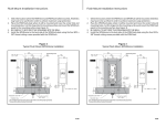
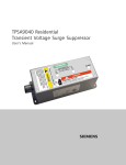
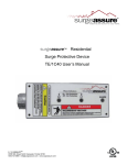
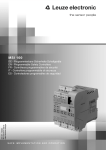
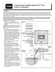
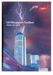
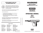
SPD4home
User Manual
Manuel d’ Installation
s
Total Home Surge Protection
SPD4home
Surge Protection for Point-of-Entry
User Manual - USA (English)
www.usa.siemens.com/spd
Features and Benefits
▪▪
▪▪
▪▪
▪▪
▪▪
▪▪
▪▪
UL listed
Rated for single phase panels up to 400 amps
Installation flexibility
Audible Alarm
Internal diagnostics keep you informed
Guaranteed lightning protection
10-year product warranty*
Siemens SPD4home shields motor-driven appliances in residential and light commercial
applications against electrical power surge damage, including lightning, from entering
through the main electrical service panel.
Multiple MOV technology with thermal disconnect to prevent catastrophic failure. The
two LED lights indicate protection status. The audible alarm alerts you when protection
is disrupted.
Technical Specifications
AC SURGE PROTECTION
Thermal Fusing
Catastrophic Surge Circuit
Single Pulse Energy Dissipation
Spike Capacity
Line Voltage
VPR MCOV
Rated Voltage
Response Time
Short Cicuit Rating
NEMA 4X Enclosure
AGENCY APPROVALS & WARRANTY
UL/cUL Listings**
Meets IEEE C62.41.1 Requirements
Product Warranty
CATALOG NUMBER
SPD4home
UL Model No. - TPSA9040
* See www.usa.siemens.com/spd for warranty details.
1
Yes
Yes
1080 Joules
40,000A
120/240 1 Phase 50/60 Hz
700V
150V
<1 nanosecond
25,000A
Standard
1449 SPD
Yes
10 Years
Point-of-Entry Protector
Installation Instructions:
DO NOT INSTALL DURING ACTIVE STORM CONDITIONS.
Note: It is important to keep all connecting leads as short as
possible. Additionally, conductors should be twisted together
for as much of the wire run as possible.
1. Ensure power to the panelboard has been removed.
2. Remove the screws securing the outer panelboard
cover to the panelboard (see Figure 1).
3. If SPD has optional flush mount kit (FMKITC)
please follow instructions provided with the
SPD4Flush and then proceed to #4 in this manual.
4. Select the location where the SPD4home will
be mounted (should be based on the internal
configuration of the panelboard and the
physical surroundings outside the panelboard).
Note that the SPD4home’s lead length must be
minimized to achieve maximum performance.
Once the location and threaded connection has
been determined, drill or punch an appropriate
size hole in the top, bottom or side surface of
the panelboard. The ideal mounting location
will also allow the SPD4home to be secured to
the wall or panel in addition to using a chase
nipple or short threaded pipe.
5. Push the leads from the SPD4home through
the hole toward the inside of the panelboard.
Secure the SPD4home to the panelboard.
6. If possible, to provide extra rigidity in the
installation, attach the SPD4home to the wall or
panel using installer supplied hardware.
7. Trim the leads from the SPD4home as short
as possible, but still allowing the following
connections to be made (see Figure 1):
▪▪ Black wires go to the nearest free 20 Amp 2
pole circuit breaker. The phase of each lead is
marked with a white band and letter designator (L1 or L2). Connect the SPD4home leads
to the appropriate phases. (In all installations,
Always install the SPD4home on the load
side of the main disconnect
Figure 1: SPD4home
Mounting Screws
(4 places, not supplied)
Installation Wiring Diagram
for WYE Applications
Interconnecting Wiring
· Minimize length
· Avoid Sharp Bends
Integral Chase Nipple
(nut installed)
Chase Nipple Nut
20 Amp
Breaker
Wiring to Breaker:
L1- Black
L2- Black
Outer Breaker Panel
Cover Screws
(6 places, typical)
Panelboard
Wiring to Neutral or
Ground Bus:
Ground - Green
Neutral - White (if used)
it is not critical which black wire goes to the
positions on the circuit breaker.)
▪▪ Connect the white Neutral wire to the neutral
bar using a set screw (in some applications,
this connection may not be required).
▪▪ Connect the green Ground wire to the panelboard ground.
8. Install the panelboard cover. Note: Conducting
dielectric and/or high potential testing will
cause internal damage to the SPD4home
unit. DO NOT perform dielectric or high
potential tests with the phase or neutral
SPD4home wires connected.
9. Apply power to the panelboard. The two
LEDs will illuminate on the SPD4home. If
any connected phase LED on the SPD4home
does not illuminate, remove power, check all
connections and test again. If any connected
phase LED still does not illuminate, contact
Siemens Technical Support 1-888-333-3545.
Operation
The Siemens Residential surge suppressor normally
requires no remedial action. However in the event of
a power anomaly or a malfunction, the operational
status may change and may require action.
The table below outlines the operating conditions of
the TPSA9040 and any correction action if required.
Light
1
Light
2
Alarm
Red
Audible
Alarm
Corrective
Action
Out
Out
Out
Off
Reset Breaker if Breaker
Trips Replace Unit
Green
Green
Out
Green
Blinks
Sounds
Replace Unit
Green
Out
Blinks
Sounds
Replace Unit
Green
Green
Blinks
Sounds
Check Neutral to
Ground Connection
before Replacing Unit
No Action
This device features internal circuitry that will
disconnect the surge protective component at the
end of its useful life. Power will maintain to the load,
however the load is now unprotected. Follow the
manufacturer’s instructions for replacing the device.
Siemens Industry, Inc.
5400 Triangle Parkway
Norcross, GA 30092
888-333-3545
[email protected]
www.usa.siemens.com/spd
Metal Wall of Panelboard
2
Total Home Surge Protection
SPD4home
Surge Protection for Point-of-Entry
User Manual - Canada (English / Anglais)
www.purgethesurge.ca
Features and Benefits
▪▪
▪▪
▪▪
▪▪
▪▪
▪▪
▪▪
cUL listed
Rated for single phase panels up to 400 amps
Installation flexibility
Audible Alarm
Internal diagnostics keep you informed
Guaranteed lightning protection
10-year product warranty*
Siemens SPD4home shields motor-driven appliances in residential and light commercial
applications against electrical power surge damage, including lightning, from entering
through the main electrical service panel.
Multiple MOV technology with thermal disconnect to prevent catastrophic failure. The
two LED lights indicate protection status. The audible alarm alerts you when protection
is disrupted.
Technical Specifications
AC SURGE PROTECTION
Thermal Fusing
Catastrophic Surge Circuit
Single Pulse Energy Dissipation
Spike Capacity
Line Voltage
VPR MCOV
Rated Voltage
Response Time
Short Cicuit Rating
NEMA 4X Enclosure
AGENCY APPROVALS & WARRANTY
UL/cUL Listings**
Meets IEEE C62.41.1 Requirements
Product Warranty
CATALOG NUMBER
SPD4home
UL Model No. - TPSA9040
* See www.purgethesurge.ca for warranty details.
3
Yes
Yes
1080 Joules
40,000A
120/240 1 Phase 50/60 Hz
700V
150V
<1 nanosecond
25,000A
Standard
1449 SPD
Yes
10 Years
Point-of-Entry Protector
Installation Instructions:
DO NOT INSTALL DURING ACTIVE STORM CONDITIONS.
Note: It is important to keep all connecting leads as short as
possible. Additionally, conductors should be twisted together
for as much of the wire run as possible.
1. Ensure power to the panelboard has been removed.
2. Remove the screws securing the outer panelboard
cover to the panelboard (see Figure 1).
3. If SPD has optional flush mount kit (FMKITC)
please follow instructions provided with the
SPD4Flush and then proceed to #4 in this manual.
4. Select the location where the SPD4home will
be mounted (should be based on the internal
configuration of the panelboard and the
physical surroundings outside the panelboard).
Note that the SPD4home’s lead length must be
minimized to achieve maximum performance.
Once the location and threaded connection has
been determined, drill or punch an appropriate
size hole in the top, bottom or side surface of
the panelboard. The ideal mounting location
will also allow the SPD4home to be secured to
the wall or panel in addition to using a chase
nipple or short threaded pipe.
5. Push the leads from the SPD4home through
the hole toward the inside of the panelboard.
Secure the SPD4home to the panelboard.
6. If possible, to provide extra rigidity in the
installation, attach the SPD4home to the wall or
panel using installer supplied hardware.
7. Trim the leads from the SPD4home as short
as possible, but still allowing the following
connections to be made (see Figure 1):
▪▪ Black wires go to the nearest free 20 Amp 2
pole circuit breaker. The phase of each lead is
marked with a white band and letter designator (L1 or L2). Connect the SPD4home leads
to the appropriate phases. (In all installations,
Always install the SPD4home on the load
side of the main disconnect
Figure 1: SPD4home
Mounting Screws
(4 places, not supplied)
Installation Wiring Diagram
for WYE Applications
Interconnecting Wiring
· Minimize length
· Avoid Sharp Bends
Integral Chase Nipple
(nut installed)
Chase Nipple Nut
20 Amp
Breaker
Wiring to Breaker:
L1- Black
L2- Black
Outer Breaker Panel
Cover Screws
(6 places, typical)
Panelboard
Wiring to Neutral or
Ground Bus:
Ground - Green
Neutral - White (if used)
it is not critical which black wire goes to the
positions on the circuit breaker.)
▪▪ Connect the white Neutral wire to the neutral
bar using a set screw (in some applications,
this connection may not be required).
▪▪ Connect the green Ground wire to the panelboard ground.
8. Install the panelboard cover. Note: Conducting
dielectric and/or high potential testing will
cause internal damage to the SPD4home
unit. DO NOT perform dielectric or high
potential tests with the phase or neutral
SPD4home wires connected.
9. Apply power to the panelboard. The two
LEDs will illuminate on the SPD4home. If
any connected phase LED on the SPD4home
does not illuminate, remove power, check all
connections and test again. If any connected
phase LED still does not illuminate, contact
Siemens Technical Support 1-888-333-3545.
Operation
The Siemens Residential surge suppressor normally
requires no remedial action. However in the event of
a power anomaly or a malfunction, the operational
status may change and may require action.
The table below outlines the operating conditions of
the TPSA9040 and any correction action if required.
Light
1
Light
2
Alarm
Red
Audible
Alarm
Corrective
Action
Out
Out
Out
Off
Reset Breaker if Breaker
Trips Replace Unit
Green
Green
Out
Green
Blinks
Sounds
Replace Unit
Green
Out
Blinks
Sounds
Replace Unit
Green
Green
Blinks
Sounds
Check Neutral to
Ground Connection
before Replacing Unit
No Action
This device features internal circuitry that will
disconnect the surge protective component at the
end of its useful life. Power will maintain to the load,
however the load is now unprotected. Follow the
manufacturer’s instructions for replacing the device.
Siemens Canada Limited
2 Kenview Boulevard
Brampton, Ontario L6T 5E4, Canada
SPD Hotline : 1-888-333-3545
[email protected]
www.purgethesurge.ca
Metal Wall of Panelboard
4
Limiteur général de surtension
SPD4home
SPD4home pour tableau résidentiel
Manuel d’installation - Canada (Français/
French)
www.purgethesurge.ca
Caractéristiques et avantages
▪▪
▪▪
▪▪
▪▪
▪▪
▪▪
▪▪
Homologation cUL
Capacité nominale : tableaux monophasés, maximum de 400 A
Souplesse d’installation
Alarme sonore
Mode diagnostic interne pour transmission de l’information
Protection garantie contre la foudre
Produit garanti 10 ans*
Le suppresseur de surtensions Siemens SPD4home protège les appareils à moteur en
service résidentiel ou commercial léger contre les dommages causés par les surtensions,
y compris la foudre, pouvant traverser le tableau d’alimentation principal.
Dispositifs MOV (varistance à oxyde métallique) multiples, avec coupe-circuit thermique,
pour éviter les défaillances catastrophiques. Deux voyants à DEL indiquent l’état de
protection. L’alarme sonore prévient lorsque la protection est perturbée.
Données techniques
PROTECTION CONTRE LES SURTENSIONS C.A.
Fusible thermique
Oui
Circuit antisurtension catastrophique
Oui
Dissipation d’énergie monoimpulsion
1080 Joules
Capacité transitoire
40,000A
Tension secteur
120/240 1 Phase 50/60 Hz
VPR MCOV
700V
Tension nominale
150V
Temps de réponse
<1 nanoseconde
Tenue au court-circuit
25,000A
Boîtier NEMA 4X
Standard
HOMOLOGATIONS ET GARANTIE
UL/cUL Listings**
Meets IEEE C62.41.1 Requirements
Product Warranty
NUMERO DE PIÈCE
SPD4home
UL Model No. - TPSA9040
* See www.purgethesurge.ca for warranty details.
5
1449 SPD
Oui
10 ans
Au point d’entrée
Instructions d’installation
NE PAS INSTALLER PENDANT UN ORAGE.
Remarque : Il est important que tous les fils de connexion
soient aussi courts que possible. De plus, les conducteurs
doivent être torsadés sur tout leur parcours, si possible.
1. S’assurer que l’alimentation du tableau a été coupée.
2. Retirer les vis de fixation du couvercle du tableau
3.
4.
5.
6.
7.
▪▪
(v. Ill. 1).
Si vous allez installer un montage encastré
(optionnel) veuillez suivre les instructions du
manuel qui est fourni avec le FMKITC. Ensuite
veuillez procéder au #4 de ce manuel.
Choisir l’endroit où le SPD4home sera installé (selon
la configuration des composants internes du tableau
et celle des éléments qui l’entourent). Noter que la
longueur des fils de connexion du SPD4home doit
être réduite au minimum pour obtenir un rendement
maximum. Apres avoir déterminé l’endroit d’installation
et le mamelon de traversée de cloison installé, percer
ou découper un trou d’une taille appropriée au dessus,
au dessous, ou sur un côté du tableau. L’emplacement
idéal de montage permettra de fixer le SPD4home au
mur ou au tableau, en plus d’un mamelon de traversée
de cloison ou un équivalent.
Passer les fils du SPD4home dans le trou vers l’intérieur
du tableau. Fixer le SPD4home au tableau.
Si possible, afin de rendre l’installation plus rigide,
fixer le SPD4home au mur ou au tableau à l’aide du
matériel fourni
Raccourcir le plus possible les fils du SPD4home, tout en
permettant les connexions suivantes (v. Ill. 1).
Les fils noirs se raccordent au coupe-circuit
bipolaire de 20 A libre le plus près. La phase de
chaque fil est indiquée par une bande blanche et
un code (L1 ou L2). Brancher les fils du SPD4home
aux phases qui conviennent (l’un ou l’autre des
fils noirs peut être raccordé à l’une ou l’autre des
bornes du coupe-circuit).
Toujours installer un SPD4home au
sectionneur du côté charge
III. 1: SPD4home
Vis de montage (4)
non fournies
Schéma de câblage pour
installations en étoile
Câblage d’interconnexion
-Minimiser la longueur
-Éviter les angles prononcés
20 Amp
Breaker
Mamelon de
traversée de cloison
(écrou posé)
Écrou de mamelon de
traversée de cloison
Câblage vers
coupe-circuit
L1- Noir
L2- Noir
Vis de fixation du
couvercle du tableau
(ordinairement 6)
Panelboard
Parci métallique du tableau
Câblage vers neutre
ou barre de masse:
Moooo - Vert
Neutre - Blanc
(s’il y a lieu)
▪▪
▪▪
8.
9.
Connecter le conducteur neutre blanc à la barre
neutre au moyen d’une vis de blocage (cette
connexion n’est pas nécessaire dans certaines
installations).
Raccorder le conducteur de masse vert à la
masse du tableau.
Poser le couvercle du tableau. Note : L’exécution
d’essais diélectriques endommagera le
SPD4home. NE PAS effectuer d’essais
diélectriques lorsque les conducteurs de phase
ou neutres du SPD4home sont connectés.
Réalimenter le tableau. Les deux voyants à DEL
du SPD4home s’allumeront. Si l’un ou l’autre
des voyants de phase à DEL du SPD4home ne
s’allume pas, couper l’alimentation, vérifier tous les
branchements et réessayer. Si, de nouveau, l’un ou
l’autre des voyants de phase à DEL ne s’allume pas,
communiquer avec le service d’assistance Siemens
au 1-888-333-3545.
Operación
El supresor de sobretensiones Siemens Residencial
normalmente no requiere ninguna acción correctiva.
Sin embargo, en el caso de una anomalía de potencia
o un mal funcionamiento, el estado operativo puede
cambiar y puede requerir una acción preventiva.
El siguiente cuadro muestra las condiciones de
funcionamiento del TPSA9040 y cualquier acción
correctiva si es necesario.
Luz
1
Luz
2
Alarma
Rojo
Alarma
Audible
Acción
Correctiva
Apagado
Apagado
Apagado
Apagado
Resetear el interruptor,
si falla, cambie la unidad
Verde
Verde
Apagado
Verde
Parpadeo
Sonidos
Reemplazar la unidad
Verde
Apagado
Parpadeo
Sonidos
Reemplazar la unidad
Verde
Verde
Parpadeo
Sonidos
Revise la conexión del
neutro a tierra, antes de
reemplazar la unidad
No acción
Este dispositivo cuenta con un circuito interno que
desconectará el componente de protección contra
sobretensiones al final de su vida útil. La Potencia
se mantendrá en la carga, sin embargo, la carga se
encontrará sin protección. Siga las instrucciones del
fabricante para la sustitución del dispositivo.
Siemens Canada Limitée
2 Kenview Boulevard
Brampton, Ontario L6T 5E4, Canada
SPD Hotline : 1-888-333-3545
[email protected]
www.purgethesurge.ca
6
s
888-333-3545
12.28.12.lh #8035