1
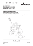
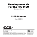
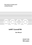
IO-Link USB Master
USB-2-IOL-0001
BEDIENUNGSANLEITUNG
INSTRUCTION
MANUAL
MODE D'EMPLOI
Hans Turck GmbH & Co.KG • D–45466 Mülheim an der Ruhr • Germany • www.turck.com
S 1810/01
1 /0709
USB Master USB-2-IOL-0001
2 /0709
Hans Turck GmbH & Co.KG • D–45466 Mülheim an der Ruhr • Germany • www.turck.com
Inhaltsverzeichnis/Table of Contents/Table des matières
Seite/page
1
Gerätekurzbeschreibung/Short description/Description brève
4
2
USB-Anschluss/USB connection/Raccordement USB
4
3
IO-Link-Anschluss/IO-Link connection/Raccordement IO-Link
4
4
Anschluss des Steckernetzteils/Connection of the wall power supply/
Raccordement de l‘alimentation externe
5
5
LED-Anzeigen/LED indications/Indications par LED
6
6
Abmessungen/Dimensions/Dimensions
7
Installation/Installation/Installation
7
7.1
Installation der Software/Installing the software/Installation du logiciel
7
7.2
Installation von USB-Treiber und CommDTM/How to install the USB driver and
CommDTM/Installation du pilote USB et du CommDTM
8
7.3
Installation der Hardware/How to install the hardware/Installation du matériel
8
7.4
Starten von PACTware™/How to start PACTware™/Démarrer le PACTware™
8
7.5
Gerätekatalog aktualisieren/How to actualize the device catalog/Actualiser le catalogue d‘appareils
8
7.6
IO-Link CommDTM auswählen/Selecting IO-Link CommDTM/Sélectionner le CommDTM IO-Link
8
7.7
CommDTM in das Projekt (HOST PC) übernehmen/How to add the CommDTM to
the project (HOST PC)/Reprendre le CommDTM dans le projet (HOST PC)
9
7.8
Verbindung zum CommDTM aufbauen/How to setup connection to the CommDTM/
Etablir la connexion CommDTM
10
Online-Parameter des CommDTM aufrufen/How to request the online parameters of the
CommDTM/Appeler les paramètres en ligne du CommDTM
11
Online-Parameter des IO-Link-USB-Masters/How to request the online parameters of the
IO-Link USB master/Paramètres en ligne du IO-Link USB master
12
7.11
Geräte-DTM installieren/How to install the Device DTM/Installer le DTM d‘appareil
13
7.12
Gerätekatalog aktualisieren/How to actualize the device catalog/Actualiser le catalogue d‘appareils
13
7.13
Projekt öffnen/How to open a project/Ouvrir le projet
13
7.14
Geräte-DTM auswählen/Select device DTM/Sélectionner le DTM d‘appareils
13
7.15
Geräte-DTM in das Projekt übernehmen/How to request the online
parameters of the device DTM/Reprendre le DTM d‘appareil dans le projet
14
Online-Parameter des Geräte-DTM aufrufen/How to request the online parameters
of the deviceDTM/Appeler les paramètres en ligne du DTM d‘appareil
15
Änderung der Geräte-Parameter im Onlinemodus/How to change the device parameters
online/Modification des paramètres des appareils dans le mode en ligne
16
7.9
7.10
7.16
7.17
Hans Turck GmbH & Co.KG • D–45466 Mülheim an der Ruhr • Germany • www.turck.com
3 /0709
USB Master USB-2-IOL-0001
1 Gerätekurzbeschreibung
1 Short description
1 Description brève
Der IO-Link-USB-Master stellt
die Schnittstelle zur überlagerten
Steuerung zur Verfügung und
steuert die Kommunikation mit
den angeschlossenen IO-LinkGeräten.
The IO-Link USB master is the
interface to the higher lever control
unit and controls the communication with the connected IO-Link
devices.
Le IO-Link USB master sert de
l‘interface à la commande supérieure et règle la communication
avec les appareils IO-Link raccordés.
2 USB-Anschluss
2 USB connection
2 Raccordement USB
Der USB-Anschluss dient als
Kommunikationsschnittstelle
zwischen dem Interface und dem
PC. Die Verbindung kann mit Hilfe
des beigelegten Kabels realisiert
werden.
Die Pinbelegung ist unten in Fig.
1 dargestellt.
The USB connection serves as
communication interface between
the interface and the PC.
The connection is established with
the supplied cable.
Le raccordement USB sert d‘interface de communication entre
l‘interface et le PC. Le raccordement peut être réalisé par le
câble qui fait partie de la livraison.
Le raccordement des broches est
visualisé dans le schéma Fig. 1
ci-dessous.
Fig. 1
2 1
3 4
The pin assignment is demonstrated below in Fig. 1.
Pin
Signal
Funktion/Function/Fonction
1
5 VDC
VBUS 5 VDC/500 mA
2
D–
Data –
3
D+
Data +
4
GND
0V
3 IO-Link-Anschluss
3 IO-Link connection
3 Raccordement IO-Link
Ein Kabel mit beidseitiger M12Kupplung (A-codiert) dient als
Schnittstelle zu einem IO-Linkfähigem Sensor/Aktor
(Kabel nicht im Lieferumfang).
Die Pinbelegung ist unten in
Fig. 2 dargestellt.
Cable with M12 female connector
(A-coded) on both ends, used as
interface to an I/O-Link capable
sensor/actor with IO-Link
(cable not included in delivery).
The pin assignment is shown
below in Fig. 2.
Un câble avec connecteur femelle M12 aux deux extrémités
(codage A) sert d’interface à un
détecteur/actuateur IO-Link
(le câble n’est pas inclu).
La Fig. 2 montre le raccordement
des broches.
Fig. 2
2
3
1
5
4 /0709
4
Pin
Signal
Funktion/Function/Fonction
1
24 VDC
24 VDC/1,6 A/40 mA
2
–
n. c.
3
GND
0V
4
C/Q (IO-Link)
Communication/Switching (IO-Link)
5
–
n. c.
Hans Turck GmbH & Co.KG • D–45466 Mülheim an der Ruhr • Germany • www.turck.com
4 Anschluss des Steckernetzteils
4 Connection of the wall
power supply
4 Raccordement de l‘alimentation externe
ì ACHTUNG
Möglicher Laptopschaden
Benötigt das IO-Link-Gerät
mehr als 40 mA, muss das
Steckernetzteil verwendet
werden!
Beachten Sie, dass manche
Laptops insbesondere auf
Anlaufströme besonders
empfindlich reagieren.
Verwenden Sie im Zweifelsfall das Steckernetzteil.
ì ATTENTION
Risk of notebook defect
If the IO-Link device
needs more than 40 mA,
it has to be used the
plug-in supply!
Please consider that some
notebooks react sensitivly
to starting current. In case
of doubt, please use the
plug-in power supply.
ì ATTENTION
Dommage éventuel à
l‘ordinateur portable
Si l‘appareil IO-Link consomme plus de 40 mA, l‘alimentation externe doit être utili sée! Notez que beaucoup
d‘ordinateurs portables réagissent de manière sensible aux courants de démarrage. En cas de doute, il est
recommandé d‘utiliser l‘alimentation externe.
Ein USB-Port liefert standardmäßig 500 mA bei 5 V.
Ohne Steckernetzteil liefert der
IO-Link-Master ca. 40 mA bei
24 V. Damit können bereits viele
IO-Link-Geräte betrieben werden.
An USB port provides as standard 500 mA with 5 V. Without
plug-in power supply the IO-Link
master provides approx. 40 mA
with 24 V. Enough to operatemany IO-Link devices.
Un port USB fournit 500 mA
en standard à 5 V. Sans alimentation externe, le maître IO-Link
fournit env. 40 mA à 24 V ce qui
permet déjà d‘utiliser beaucoup
d‘appareils IO-Link.
Wird für das IO-Link-Gerät mehr
Strom (auch Anlaufstrom) benötigt, muss das Steckernetzteil
verwendet werden.
If more power (also starting current) is needed, for the IO-Link
device, use the plug-in power
supply.
Si l‘appareil IO-Link nécessite
plus de courant (incl. courant de
démarrage), l‘alimentation externe doit être utilisée.
Die Pinbelegung des Netzteils ist
unten in Fig. 3 dargestellt.
The pin assignment of the plug-in
power supply is shown below in
Fig. 3.
La Fig. 3 montre le raccordement
des broches de l‘alimentation.
Fig. 3
1
2
3
Pin
Signal
1
24 VDC
2
GND
3
GND
Hans Turck GmbH & Co.KG • D–45466 Mülheim an der Ruhr • Germany • www.turck.com
5 /0709
USB Master USB-2-IOL-0001
5 LED-Anzeigen
5 LED indications
5 Indications par LED
Die LEDs am IO-Link-USBMaster haben die folgende Bedeutung:
The LEDs on the IO-Link USB
master have the following meaning:
Les LEDs du IO-Link USB master
ont la signification suivante:
Bezeichnung/
Description/Description
Farbe/Color/
Couleur
Bedeutung/Meaning/Signification
IO-Link
Grün/
green/
vert
Die LED blinkt, wenn keine IO-Link-Verbindung vorhanden ist, und leuchtet, wenn die IO-Link-Verbindung aktiv
ist./
The LED flashes if there is no IO-Link connection and
lights if the IO-Link connection is active./
Le LED clignote s‘il n‘y a pas de raccordement IO-Link
et est allumée en continu si le raccordement IO-Link est
actif.
USB
Gelb/
yellow/
jaune
Während einer Datenübertragung blinkt die LED./
During a data transmission the LED flashes./
La LED clignote pendant la transmission de données.
Error
Rot/
red/
rouge
Leuchtet, wenn ein Fehler aufgetreten ist.
(Kurzschluss, Datenübertragungsfehler)/
Lights in case of errors.
(short circuit, errors in data transmission)/
S‘allume en cas d‘erreur (court-circuit,
erreur de transmission de données)
6 Abmessungen/Dimensions/Dimensions
Fig. 4
Error
USB
IO-Link
DC 24V
USB-B
24
69
M12 x 1
6 /0709
54
12
Hans Turck GmbH & Co.KG • D–45466 Mülheim an der Ruhr • Germany • www.turck.com
7
Installation
7
Installation
7.1 Installation der Software
Mit der Softwarekombination aus
FDT-Rahmenapplikation (bspw.
PACTware™) und dem DTM
(Device Type Manager) können
kommunikationsfähige Feldgeräte
unterschiedlicher Hersteller unter
Verwendung der IO-Link-Kommunikationsschnittstelle konfiguriert und parametriert werden.
PACTware™ dient dabei entsprechend der FDT-Spezifikation
1.2.1 als Rahmenapplikation für
einzelne DTM. Diese werden von
den jeweiligen Geräteherstellern
bereitgestellt. PACTware™ ist mit
den DTM kompatibel, die nach
der FDT-Spezifikation 1.2 oder
1.2.1 implementiert wurden.
7.1 Installing the software
Communication-capable field
devices of different manufactures
are configured and parameterized
via the IO-Link interface using a
FDT frame application (e.g PACTware™) and the DTM (Device
Type Manager). PACTware™
is applied as frame application
for individual DTMs according
to the FDT specification 1.2.1.
The DTMs are provided by the
manufacturers. PACTware™ is
compatible to those DTMs that
are implemented according to the
FDT specification 1.2 or 1.2.1.
Über den CommDTM wird
die Kommunikation mit dem
Feldgerät unter Verwendung von
Protokollen wie bspw. IO-Link
oder PROFIBUS-DP hergestellt.
Der CommDTM ist auch auf anderen FDT-Rahmenapplikationen
lauffähig, da es sich um einen
firmenübergreifenden Standard
handelt.
The communication with the
field device is established via the
CommDTM using IO-Link or
PROFIBUS-DP protocols. The
CommDTM software works also
with other FDT frame applications
because it is a cross-company
standard.
Während der Installation der FDTRahmenapplikation PACTware™
folgen Sie bitte den Angaben der
Installationsroutine.
Nach der Installation der FDTRahmenapplikation können Sie
mit der Installation des CommDTM beginnen.
Please follow the setup routine
when installing the FDT frame
application PACTware™.
HINWEIS
Die FDT-Rahmenapplikation PACTware™, der
aktuelle CommDTM des
IO-Link-USB-Masters und
die jeweiligen Geräte-DTM
finden Sie auch auf unserer
Internet-Seite
www.turck.de/io-link.
After setting up the FDT frame
application please install CommDTM.
NOTE
The FDT frame application
PACTware™, the latest
CommDTM of the IO-Link
USB master and the related
device DTM can be downloaded from our website
www.turck.de/io-link.
7
Installation
7.1 Installation du logiciel
La combinaison de logiciel de
l‘application cadre FDT (par
exemple PACTware™) et le DTM
(Device Type Manager) permet de
configurer et de paramétrer des
appareils de terrain susceptibles
de communiquer de différents
constructeurs par l‘utilisation de
l‘interface de communication
IO-Link.
Conformément à la spécification
FDT 1.2.1, PACTware™ sert
d‘application cadre pour les DTM
individuels. Ceux-ci sont mis à
disposition par les constructeurs
d‘appareils respectifs.
PACTware™ est compatible avec
les DTM, qui ont été implémentés
suivant la spécification FDT 1.2
ou 1.2.1.
Le CommDTM permet d‘établir la
communication avec l‘appareil de
terrain en utilisant des protocoles
tels qu‘IO-Link ou PROFIBUS-DP.
Le CommDTM est également
utilisable sur d‘autres applications
cadre FDT, comme il s‘agit d‘une
norme universelle.
Veuillez suivre les instructions
de la routine d‘installation pour
l‘installation de l‘application cadre
FDT PACTware™.
Après l‘installation de l‘application
cadre FDT vous pouvez entamer
l‘installation du CommDTM.
NOTE
L‘application cadre FDT
PACTware™, le CommDTM
actuel du maître IO-Link
USB et les DTM d‘appareils
respectifs peuvent être
consultés sur le site web
www.turck.de/io-link.
Hans Turck GmbH & Co.KG • D–45466 Mülheim an der Ruhr • Germany • www.turck.com
7 /0709
USB Master USB-2-IOL-0001
7.2 Installation von USBTreiber und CommDTM
Installieren Sie bitte die mitgelieferte Software, bevor Sie den
IO-Link-USB-Master
mit dem Rechner verbinden.
➤ Starten Sie die „Setup.exe“
auf der beigefügten CD-ROM
und folgen Sie der Installationsroutine. Im Lieferumfang
des IO-Link-USB-Master
enthalten sind u. a. der USBTreiber und der CommDTM.
7.2 How to install the USB
driver and CommDTM
Please install the included software prior to connecting the
IO-Link USB master to the
computer.
➤ Start “Setup.exe“ on the
included CD-ROM and
follow the setup routine.
The USB driver and the
CommDTM are included
in the delivery of the IOLink USB master.
7.2 Installation du pilote USB
et du CommDTM
Installez d‘abord le logiciel inclu
avant de raccorder le IO-Link
USB master à l‘ordinateur.
7.3 Installation der Hardware
➤ Verbinden Sie den IO-LinkUSB-Master über das
mitgelieferte USB-Adapterkabel mit dem Rechner.
➤ Zur Verbindung des IO-LinkGerätes (bspw. IO-Link fähiger Sensor) mit dem IO-LinkUSB-Master verwenden Sie
eine beidseitig mit M12 x 1Steckverbindern konfektionierte 3- oder 4-polige Sensorleitung (siehe Fig. 2).
➤ Versorgen Sie anschließend
den IO-Link-USB-Master
über das mitgelieferte
24-VDC-Steckernetzteil mit
Energie. Das System ist jetzt
betriebsbereit (siehe Seite 5).
7.3 How to install the hard
ware
➤ Connect the IO-Link USB
master to the computer with
the supplied USB adapter
cable
➤ The IO-Link device (e.g. IOLink capable sensor) and
the IO-Link USB master
are connected with a 3 or
4-pole sensor cable featuring M12 x 1 connectors
on both ends.(see Fig. 2).
➤ Power the IO-Link USB
master via the 24 VDC
plug-in power supply.
The system is now ready
for use (see page 5).
7.3 Installation du matériel
➤ Raccordez le IO-Link USB
master à l‘ordinateur par
le câble d‘adaptateur USB
inclu.
➤ Utilisez un câble de raccordement de détecteurs
à 3 ou 4 pôles avec des
connecteurs M12 x 1 aux
deux extrémités pour lier
l‘appareil IO-Link (par exemple détecteur compatible
avec IO-Link) au IO-Link
USB master.
➤ Ensuite branchez le maître
IO-Link USB par l‘alimentation externe 24 VDC incluse.
Le système est maintenant
opérationnel (voir page 5).
7.4 Starten von PACTware™
➤ Starten Sie das
Programm „PACTware™“.
7.4 How to start PACTware™
➤ Start the program
“PACTware™“.
7.4 Démarrer le PACTware™
➤ Démarrez le programme
„PACTware™“.
7.5 Gerätekatalog aktualisieren (Fig. 5)
Um mit dem IO-Link-USB-Master
arbeiten zu können, muss der
Gerätekatalog der FDT-Rahmenapplikation aktualisiert werden.
Das Aktualisieren des Gerätekataloges ist nach jeder DTMNeuinstallation erforderlich.
➤ Hierzu öffnen Sie den
Gerätekatalog (bspw. über
F3) und aktualisieren Sie
diesen über die Schaltfläche
„Gerätekatalog aktualisieren“ (siehe Fig. 5).
Der CommDTM ist in den Gerätekatalog aufgenommen worden.
7.5 How to actualize the
device catalog (Fig. 5)
In order to work with the IO-Link
USB master, the device catalog
of the FDT frame application
must be actualized. The device
catalog must always be actualized after installing a new DTM.
7.5 Actualiser le catalogue
d‘appareils (Fig. 5)
Pour pouvoir travailler avec le
IO-Link USB master, il faut actualiser le catalogue d‘appareils de
l‘application cadre FDT.
La mise à jour du catalogue d‘appareils est requise après chaque
nouvelle installation du DTM.
➤ Ouvrez à cet effet le catalogue d‘appareils (par ex. par
F3) et actualisez-le par le
bouton „update device
catalog“ (voir Fig. 5).
8 /0709
➤
For this purpose open the
device catalog (press F3)
and actualize by clicking
on “update device
catalog“(see Fig. 5)
The CommDTM is now added to
the device catalog.
➤
Cliquez sur „Setup.
exe“ se trouvant sur le
CD-ROM inclu et suivez la
routine d‘installation.
Le pilote USB et le Comm
DTM font partie de la livraison du IO-Link USB master.
Le CommDTM est repris dans le
catalogue d‘appareils.
Hans Turck GmbH & Co.KG • D–45466 Mülheim an der Ruhr • Germany • www.turck.com
HINWEIS
Der Vorgang lässt sich nur
ausführen, wenn kein Projekt
geöffnet ist (ggf. aktuelles
Projekt vor dem Schließen
speichern).
NOTE
To execute this step, please
make sure that all projects
are saved and closed.
NOTE
Le procédé se laisse effectuer seulement si aucun projet
n‘est ouvert (éventuellement
mémoriser le projet actuel
avant la clôture).
7.6 IO-Link CommDTM auswählen
➤ Wählen Sie aus dem Gerätekatalog:
➔ IO-Link
➔ Treiber
➔ IO-Link-USB-Master
7.6 Selecting IO-Link
CommDTM
➤ Please select from the
device catalog
➔ IO-Link
➔ Driver
➔ IO-Link USB master
7.6 Sélectionner le CommDTM IO-Link
➤ Sélectionnez dans le catalogue d‘appareils
➔ IO-Link
➔ pilote
➔ IO-Link USB master
7.7 CommDTM in das Projekt
(HOST PC) übernehmen
(Fig. 5)
➤ Doppelklick auf den CommDTM IO-Link-USB-Master
(alternativ per Drag and
Drop bzw. rechte Maustaste
auf HOST PC und Gerät
hinzufügen).
7.7 How to add the Comm
DTM to the project
(HOST PC) (Fig. 5)
➤ Double-click on CommDTM
IO-Link USB master ( you
can also add a device with
drag and drop resp. rightclick on HOST PC).
7.7 Reprendre le CommDTM
dans le projet (HOST PC)
(Fig. 5)
➤ Double clic sur le CommDTM IO-Link USB master
(ou par drag and drop resp.
cliquez par la touche droite
de la souris sur le HOST PC
et ajouter l‘appareil.
Fig. 5
siehe/
see/voir
7.5
Hans Turck GmbH & Co.KG • D–45466 Mülheim an der Ruhr • Germany • www.turck.com
9 /0709
USB Master USB-2-IOL-0001
7.8 Verbindung zum Comm
DTM aufbauen (Fig. 6)
➤ Rechte Maustaste auf HOST
PC und Verbindung aufbauen (alternativ per Icon
innerhalb der Menüleiste
bzw. via Hauptmenü).
7.8 How to setup connection
to the CommDTM (Fig. 6)
➤ Right-click on HOST PC to
establish connection (alter
natively click on icon in the
menu bar resp. main menu.
7.8 Etablir la connexion
CommDTM (Fig. 6)
➤ Cliquer par la touche droite
de la souris sur le HOST PC
et établir la connexion (ou
par l‘icône dans la barre de
menus resp. par le menu
principal).
Fig. 6
10 /0709
Hans Turck GmbH & Co.KG • D–45466 Mülheim an der Ruhr • Germany • www.turck.com
7.9 Online-Parameter des
CommDTM aufrufen (Fig. 7)
➤ Rechte Maustaste auf
➔ IO-Link-USB-Master
➔ Weitere Funktionen
➔ Experten-Modus
7.9 How to request the online
parameters of the Comm
DTM (Fig. 7)
➤ Right-click on
➔ IO-Link USB master
➔ Additional functions
➔ Expert mode
7.9 Appeler les paramètres en
ligne du CommDTM (Fig. 7)
➤ La touche droite de la souris sur
➔ IO-Link USB master
➔ Additional functions
➔ Expert mode
Fig. 7
Hans Turck GmbH & Co.KG • D–45466 Mülheim an der Ruhr • Germany • www.turck.com
11 /0709
USB Master USB-2-IOL-0001
7.10 Online-Parameter des IOLink-USB-Masters (Fig. 8)
Mit dem Aufruf des ExpertenModus erhält der Anwender
Zugriff auf die Online-Parameter
des IO-Link-USB-Masters.
Hierzu zählen die unten aufgeführten Parametersätze:
■ Überblick
■ Geräte-Informationen
■ IO-Link-Daten
■ IO-Link-Parameter und
■ Info über
7.10 How to request the online
parameters of the IOLink USB master (Fig. 8)
Select the expert mode to access
the online parameters of the IOLink USB master. The following
parameter sets are available:
7.10 Paramètres en ligne du
IO-Link USB master (Fig. 8)
En appelant le mode expert, l‘utilisateur a accès aux paramètres
en ligne du IO-Link USB master.
Parmi ceux-ci se trouvent les
points suivants:
■
■
■
■
■
■
■
■
■
■
Die Online-Parametrierung des
angeschlossenen IO-Link-Gerätes (IO-Link Device) wird typischerweise über den InterpreterDTM bzw. über den speziellen
Geräte-DTM (DeviceDTM)
durchgeführt.
The online parameterization of
the connected IO-Link device is
typically executed via the interpreter DTM resp. via the special
DeviceDTM.
General
Device information
IO-Link data
IO-Link parameter and
About
General
Device information
IO-Link data
IO-Link parameter and
About
Les paramètres en ligne de l‘appareil IO-Link raccordé (IO-Link
device) se fait typiquement par le
DTM d‘interpréteur ou par le DTM
d‘appareil spécial (DeviceDTM).
Fig. 8
12 /0709
Hans Turck GmbH & Co.KG • D–45466 Mülheim an der Ruhr • Germany • www.turck.com
7.11 Geräte-DTM installieren
➤ Starten Sie hierzu die
Datei „Setup.exe“ des
Geräte-DTM und folgen der
Installationsroutine.
HINWEIS
Die jeweiligen Geräte-DTM
finden Sie auf unserer
Internet-Seite
www.turck.de/io-link.
7.12 Gerätekatalog aktualisieren (Fig. 5)
Das Aktualisieren des Gerätekataloges ist nach jeder DTM-Neuinstallation erforderlich.
➤ Hierzu öffnen Sie den
Gerätekatalog (bspw. über
F3) und aktualisieren Sie
diesen über die Schaltfläche
„Gerätekatalog aktualisieren“ (siehe Fig. 5).
Damit ist der Geräte-DTM in
den Gerätekatalog aufgenommen.
HINWEIS
Der Vorgang lässt sich nur
ausführen, wenn kein Projekt
geöffnet ist (ggf. aktuelles
Projekt vor dem Schließen
speichern).
7.11 How to install the Device
DTM
➤ Start “Setup.exe“ on the
included CD-ROM and
follow the setup routine.
NOTE
You find the related device
DTM on our website
www.turck.de/io-link.
7.12 How to actualize the
device catalog (Fig. 5)
The device catalog must always
be actualized after installing a
new DTM.
➤ For this purpose open the
device catalog (press F3)
and actualize by clicking
on “update device
catalog“ (see Fig. 5).
The CommDTM is now
added to the device catalog.
NOTE
To execute this step, please
make sure that all projects
are saved and closed.
7.11 Installer le DTM d‘appareil
➤ Démarrer le fichier „Setup.
exe“ du DTM d‘appareil et
suivre la routine d‘installation.
NOTE
Les DTM d‘appareils respectifs peuvent être consultés
sur le site web
www.turck.de/io-link.
7.12 Actualiser le catalogue
d‘appareils (Fig. 5)
La mise à jour du catalogue d‘appareils est requise après chaque
nouvelle installation du DTM.
➤ Ouvrir le catalogue d‘appareils (par ex. par F3) et
l‘actualiser par le bouton
“update device
catalog“ (voir Fig. 5).
Le DTM d‘appareil est ainsi
repris dans le catalogue
d‘appareils.
NOTE
Le procédé se laisse effectuer seulement si aucun
projet n‘est ouvert (éventuellement mémoriser le projet
actuel avant la clôture).
7.13 Projekt öffnen
➤ Öffnen Sie das Projekt
7.13 How to open a project
➤ Open the project
7.13 Ouvrir le projet
➤ Ouvrez le projet
7.14 Geräte-DTM auswählen
➤ Wählen Sie:
➔ Gerätekatalog
➔ Alle Geräte
➔ Turck
➔ Gerät (bspw.
PS025V-nnn-Li2UPN8X)
7.14 Select device DTM
➤ Select:
➔ Device catalog
➔ All devices
➔ Turck
➔ device (e.g.
PS025V-nnn-Li2UPN8X)
7.14 Sélectionner le DTM
d‘appareils
➤ Sélectionnez
➔ Device catalog
➔ All devices
➔ Turck
➔ device (par ex.
PS025V-nnn-Li2UPN8X)
Hans Turck GmbH & Co.KG • D–45466 Mülheim an der Ruhr • Germany • www.turck.com
13 /0709
USB Master USB-2-IOL-0001
7.15 Geräte-DTM in das Projekt übernehmen (Fig. 9)
➤ IO-Link-USB-Master im
Projekt markieren und
innerhalb des Gerätekataloges Doppelklick auf den
Geräte-DTM
„PS025V-nnn-Li2UPN8X“
(alternativ per Drag and Drop
bzw. rechte Maustaste auf
IO-Link-USB-Master innerhalb des Projektes und
Gerät hinzufügen).
7.15 How to copy the device
DTM to the project (Fig. 9)
➤ Mark IO-Link USB master in
the project and double-click
on the device DTM
“PS025V-nnn-Li2UPN8X“
in the device catalog (you
can also add a device per
drag and drop resp. rightclick on IO-Link USB master
in the project).
7.15 Reprendre le DTM d‘appareil dans le projet (Fig. 9)
➤ Marquer le IO-Link USB
master dans le projet et
double clic sur le DTM
d‘appareil dans le catalogue
d‘appareils
„PS025V-nnn-Li2UPN8X“
(ou par drag and drop resp.
cliquez par la touche droite
de la souris sur le IO-Link
USB master et ajouter l‘appareil).
Fig. 9
14 /0709
Hans Turck GmbH & Co.KG • D–45466 Mülheim an der Ruhr • Germany • www.turck.com
7.16 Online-Parameter des
Geräte-DTM aufrufen (Fig. 10)
➤ Das Gerät im Projekt
markieren (bspw. „PS025Vnnn-Li2UPN8X“), rechte
Maustaste betätigen und
Verbindung aufbauen.
➤ Durch einen Doppelklick
auf den Eintrag „PS025V
nnn-Li2UPN8X“ im Projekt
öffnet sich die Oberfläche
des Geräte-DTM und die
Online-Parameter des IOLink-Gerätes werden angezeigt.
7.16 How to request the online
parameters of the device
DTM (Fig. 10)
➤ Right-click on the device
in the project, (e.g. PS025Vnnn-Li2UPN8X), and establish connection.
➤ Double-click on PS025V
nnn-Li2UPN8X in the
project, the device DTM
window opens showing the
online parameters of the
IO-Link device.
HINWEIS
Mit dem Aufruf der OnlineParameter des IO-LinkGerätes erhält der Anwender
Zugriff auf die Sensorparameter.
NOTE
By selecting the online
parameters of the IO-Link
device, the user can access
the sensor parameters.
7.16 Appeler les paramètres
en ligne du DTM d‘appa reil (Fig. 10)
➤ Sélectionner l‘appareil dans
le projet (par ex. „PS025Vnnn-Li2UPN8X“), actionner
le bouton droit de la souris
et établir la connexion.
➤ Par un double clic sur l‘article „PS025Vnnn-Li2UPN8X“
dans le projet, l‘interface
du DTM d‘appareil s‘ouvre
et les paramètres en ligne
de l‘appareil IO-Link sont
visualisés.
NOTE
Par l‘appel des paramètres
en ligne de l‘appareil IOLink, l‘utilisateur a accès au
paramètres du détecteur.
Fig. 10
Hans Turck GmbH & Co.KG • D–45466 Mülheim an der Ruhr • Germany • www.turck.com
15 /0709
USB Master USB-2-IOL-0001
7.17 Änderung der GeräteParameter im Onlinemodus (Fig. 11)
Innerhalb des Geräte-DTM
werden die Geräteparameter
dargestellt.
7.17 How to change the device
parameters online (Fig.11)
The device parameters are displayed in the device DTM.
7.17 Modification des paramètres des appareils
dans le mode en ligne
(Fig. 11)
Les paramètres d‘appareil sont
visualisés dans le DTM d‘appareil.
➤
➤
➤
Durch Anwählen der einzelnen Parameter besteht nun
die Möglichkeit, diese nach
Applikationserfordernissen
zu verändern, wie am
Beispiel der Anzeigeneinstellung (Fig. 11) dargestellt.
To change parameters
according to the require
ments, just click on one
parameter and excute
the change, see example
(Fig. 11).
Par la sélection des paramètres individuels, il est possible de les modifier suivant
les exigences d‘application,
comme il est indiqué dans
l‘exemple de la Fig. 11.
Das Ändern des Parameters
wird durch das Bleistiftsymbol
vor dem geänderten Parameter
kenntlich gemacht.
The change is indicated with the
pen icon before the parameter
La modification du paramètre est
marquée par le symbole crayon
devant le paramètre modifié.
➤
➤
➤
➤
Wählen Sie „OK“.
Der Parametersatz wird in
das Gerät geschrieben und
das DTM schließt sich.
Wählen Sie „Übernehmen“
oder das Icon „Parameter
zum Gerät übertragen“.
Der Parametersatz wird in
das Gerät geschrieben und
der DTM bleibt geöffnet.
HINWEIS
Damit geänderte Parameter
an das Gerät übertragen
werden können, muss der
Schreibschutz aufgehoben
werden.
Das Setzen/Aufheben des
Schreibschutzes erfolgt über
das entsprechende Icon in
der Menüleiste des DTM.
16 /0709
➤
Click on “OK“. The para
meter set is now copied
to the device and the
DTM closes.
Click on “Accept“ or on
the icon “Transmit parameter to device“.
NOTE
In order to copy changed
parameters to the device,
the write protection has to
be disabled.
To enable/disable the write
protection, click on the
corresponding icon in the
menu bar of the DTM.
➤
Sélectionnez „OK“.
La valeur de paramètre est
écrite dans l‘appareil et le
DTM se ferme.
Sélectionnez „Accept“ ou
l‘icône „Transmit parameter to device“.
La valeur de paramètre est
écrite dans l‘appareil et le
DTM reste ouvert.
NOTE
Pour pouvoir transmettre
les paramètres modifiés
à l‘appareil, la protection
d‘écriture doit être annulée.
L‘activation/désactivation
de la protection d‘écriture
se fait pas l‘icône correspondante dans la barre des
menus du DTM.
Hans Turck GmbH & Co.KG • D–45466 Mülheim an der Ruhr • Germany • www.turck.com
Fig. 11
Hans Turck GmbH & Co.KG • D–45466 Mülheim an der Ruhr • Germany • www.turck.com
17 /0709
USB Master USB-2-IOL-0001
18 /0709
Hans Turck GmbH & Co.KG • D–45466 Mülheim an der Ruhr • Germany • www.turck.com
Hans Turck GmbH & Co.KG • D–45466 Mülheim an der Ruhr • Germany • www.turck.com
19 /0709
USB Master USB-2-IOL-0001
Hans Turck GmbH & Co. KG
Witzlebenstraße 7
45472 Mülheim an der Ruhr
Germany
Tel. +49 (0) 208 4952-0
20 /0709
Hans Turck GmbH & Co.KG • D–45466 Mülheim an der Ruhr • Germany • www.turck.com
Fax +49 (0) 208 4952-264
D101810 0709
*D101810ßß0709*
www.turck.com