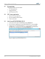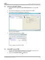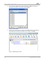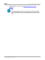
1
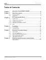
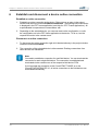
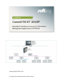
User Manual
CommDTM ET 200iSP
Extended Field Device Access for Plant Asset
Management Applications (FDT/DTM)
Version: EN-072015-1.00
© Copyright 2015 Softing Industrial Automation GmbH
Disclaimer of liability
The information contained in these instructions corresponds to the technical status at the time of printing of it and is
passed on with the best of our knowledge. The information in these instructions is in no event a basis for warranty
claims or contractual agreements concerning the described products, and may especially not be deemed as warranty
concerning the quality and durability pursuant to Sec. 443 German Civil Code. We reserve the right to make any
alterations or improvements to these instructions without prior notice. The actual design of products may deviate from
the information contained in the instructions if technical alterations and product improvements so require.
It may not, in part or in its entirety, be reproduced, copied, or transferred into electronic media.
Softing Industrial Automation GmbH
Richard-Reitzner-Allee 6
85540 Haar / Germany
Tel: + 49 89 4 56 56-0
Fax: + 49 89 4 56 56-488
Internet: http://industrial.softing.com
Email:
[email protected]
Support: [email protected]
The latest version of this manual is available in the Softing download area at: http://industrial.softing.com.
Table of Contents
Table of Contents
Chapter 1
About the
CommDTM ET 200iSP
..................................................................................4
Chapter 2
About this
manual
..................................................................................6
2.1
2.2
Chapter 3
Document history
................................................................................................ 6
Conventions ................................................................................................ 6
FDT frame
applications
..................................................................................7
3.1
3.1.1
Context menu ................................................................................................ 8
Change device
addresses
......................................................................................................
9
3.1.2
Change DTM
address
......................................................................................................
10
3.1.3
About the......................................................................................................
CommDTM ET 200iSP
11
3.1.4
Help
Chapter 4
4.1
4.2
Chapter 5
5.1
5.2
5.3
5.4
5.5
Chapter 6
...................................................................................................... 12
Licensing
..................................................................................13
License types................................................................................................ 13
Activate license
................................................................................................ 14
Example
of a project design
..................................................................................15
Prerequisites................................................................................................ 16
FDT frame application
................................................................................................ 16
Add CommDTM
................................................................................................
PROFIBUS DP-V1
16
Add CommDTM
................................................................................................
ET 200iSP
17
Add HART device
................................................................................................
DTM
17
Establish and disconnect a device online
..................................................................................20
connection
Com m DTM ET 200iSP - User Manual
3
Chapter 1 - About the Com m DTM ET 200iSP
1
About the CommDTM ET 200iSP
The SIMATIC® ET 200iSP Remote I/O, frequently used in process control plants, is an
essential structural element for the connection of HART devices to PROFIBUS. The
respective CommDTM ET 200iSP can be implemented into all FDT frame applications
according to FDT Specification 1.2 + Addendum. In this role the DTM acts as a device
driver enabling DP-V1 communication with HART devices at ET 200iSP peripheral
devices and their Device DTMs.
The CommDTM ET 200iSP considerably facilitates configuration, parameterization and
calibration, as well as commissioning, diagnosis and maintenance of field devices. You
can use the CommDTM ET 200iSP within one FDT frame application repeatedly and
concurrently (depending on the available ET 200iSP in the PROFIBUS network). To do so,
load the CommDTM ET 200iSP repeatedly into the project window. For the PROFIBUS
DP-V1 communication, a respective physical access to the PROFIBUS and a respective
CommDTM PROFIBUS DPV1 needs to be available. You can use the CommDTM
PROFIBUS DP-V1 with xEPI 2 hardware.
The CommDTM ET 200iSP is protected with a software key. You need to license the
software for unlimited use (see Licensing) 13 . CommDTM ET 200iSP functionalities can
be accessed through the context menu of the used FDT frame application.
4
Com m DTM ET 200iSP - User Manual
Chapter 1 - About the Com m DTM ET 200iSP
Figure 1: Example of a PROFIBUS network with several ET 200iSP
Com m DTM ET 200iSP - User Manual
5
Chapter 2 - About this m anual
2
About this manual
Read this manual before starting
For damages due to improper connection, implementation or operation Softing
refuses any liability according to our existing guarantee obligations.
2.1
2.2
Document history
Document version
Modifications compared to previous version
1.00
none
Conventions
The following conventions are used throughout Softing customer documentation:
Keys, buttons, menu items, commands and
other elements involving user interaction are
set in bold font and menu sequences are
separated by an arrow
Buttons from the user interface are enclosed
in brackets and set to bold typeface
Coding samples, file extracts and screen
output is set in Courier font type
Filenames and directories are written in italic
Open Start
Programs
Control Panel
Press [Start] to start the application
MaxDlsapAddressSupported=23
Device description files are located in
C:\StarterKit\delivery\software\Device
Description files
CAUTION
CAUTION indicates a potentially hazardous situation which, if not avoided, may
result in minor or moderate injury.
Note
This symbol is used to call attention to notable information that should be
followed during installation, use, or servicing of this device.
Hint
This symbol is used when providing you with helpful user hints.
6
Com m DTM ET 200iSP - User Manual
Chapter 3 - FDT fram e applications
3
FDT frame applications
The different FDT frame applications vary in functionality and naming of the individual
functions. In this User Manual the naming refers to the »FieldCare« frame application.
Complete functionality for the frame application is described in the FieldCare online help.
Figure 2: FieldCare
Com m DTM ET 200iSP - User Manual
7
Chapter 3 - FDT fram e applications
3.1
Context menu
Right-click an entry in the project window of the FDT frame application to open the context
menu. Its entries are default entries of the FDT frame application. Select Additional
functions in this window to display the entries to the respective DTM. Functionalities
displayed in gray are not supported or already opened. To select these functions, an online
connection might be required.
Integration of CommDTM ET 200iSP into a project is described in Section Example of a
project design 15 .
Figure 3: Context menu for the CommDTM ET 200iSP
8
Com m DTM ET 200iSP - User Manual
Chapter 3 - FDT fram e applications
3.1.1
Change device addresses
This functionality allows to display and change the device address of the field devices that
are connected to <%LINKNAME%>. This function is only available when being online. You
can only modify the address of field devices if the field devices support this functionality.
Figure 4: Modify device address
Proceed as follows:
1.
Right-click CommDTM ET 200iSP in the project window and select the function
Establish connection. The existing online connection is displayed in the FDT frame
application (see Help for »FDT Frame Application«).
2.
Right-click CommDTM ET 200iSP in the project window and select the function
Additional functions
Change device addresses.
3.
Click [Refresh] to start scanning for connected field devices. The field devices are
then listed in the window Change device addresses. Corresponding device names,
DTM vendors and DTM versions can only be displayed if this functionality is supported
by the frame applications.
4.
Mark the respective field device.
5.
Select a new address from the list box Current device address in the lower window
part and click [Accept]. Automatically, an online connection to the field device is
established, the address is modified, and the field device is disconnected again. In the
status bar of the window, information is displayed on whether this function has been
completed successfully, or whether the field device does not support this functionality.
Note
After changing the device address you need to set the DTM address of the
respective device DTM to the identical address.
Com m DTM ET 200iSP - User Manual
9
Chapter 3 - FDT fram e applications
Note
Not all devices support device address setting through the CommDTM ET
200iSP. Device addresses for some field devices can only be set directly at the
field device. Refer to the manual of the respective field device vendor for
detailed information.
3.1.2
Change DTM address
This functionality allows to display and to change the DTM addresses of the field device
DTMs. This function is only available when being offline. Make sure to use an identical
address both for the field device and for its respective DTM. The DTM address displayed
or set is used during connection establishment to the respective field device.
Figure 5: Change DTM address
Proceed as follows:
1.
Right-click CommDTM ET 200iSP in the project window and select the function
Additional functions
Change DTM addresses.
2.
Click [Refresh] to start scanning.
3.
The DTM addresses are then listed in the window Change DTM addresses.
Corresponding device names, DTM vendors and DTM versions can only be displayed
if this functionality is supported by the frame applications.
4.
Mark the respective DTM.
5.
Select a new address for the field device DTM from the list box Current device
address in the lower window part and click [Accept]. In the status bar of the window,
information is displayed on whether this function has been completed successfully, or
whether the DTM does not support this functionality.
Note
This function is not supported by all DTMs. You can only change the DTM
address directly through the field device DTM in the project.
10
Com m DTM ET 200iSP - User Manual
Chapter 3 - FDT fram e applications
3.1.3
About the CommDTM ET 200iSP
This functionality displays information about the installed CommDTM ET 200iSP.
Figure 6: About CommDTM ET 200iSP
Proceed as follows to open this window:
1.
In the project window right-click on CommDTM ET 200iSP.
2.
Select Additional functions
About CommDTM ET 200iSP. Information about
CommDTM ET 200iSP are displayed.
Com m DTM ET 200iSP - User Manual
11
Chapter 3 - FDT fram e applications
3.1.4
Help
In the context menu select Additional functions
Help. This function opens the User
Manual in PDF format. Adobe Acrobat Reader is required. The User Manual is available
after installing the DTM library locally on your system.
Figure 7: User Manual
12
Com m DTM ET 200iSP - User Manual
Chapter 4 - Licensing
4
Licensing
The CommDTM ET 200iSP is protected with a software key. You need to license the
software for unlimited use.
30-days demo license
Please contact our support to use the CommDTM ET 200iSP with a 30-day
trial license. Thus you obtain a test license key allowing you to use CommDTM
ET 200iSP up to 30 days with complete functionality after activation. After expiry
of the 30-days-demo version you will no longer be able to establish an online
connection. Online connections existing at the time of expiration will be
terminated.
License state
The license is generated for the current system only. A transfer to another
system is not possible. You can find the current license state in the About
CommDTM ET 200iSP window (context menu:
Additional functions
About CommDTM ET 200iSP).
Automatic licensing with Endress+Hauser frame application
If you are using an Endress+Hauser frame application, CommDTM ET 200iSP
is automatically licensed and activated and you can skip the following sections.
4.1
License types
There are two general license types:
Licensing on PC
Licensing on USB dongle (Hardlock)
Licensing on PC
The licensing on PC consists of a runtime license which activates the complete software
functionality on a PC.
Licensing on USB dongle (Hardlock)
Licensing on USB dongle activates the complete software functionality on that PC where
the dongle is connected to. The license is bound to the USB dongle. The dongle can be
used alternately with different PCs.
Com m DTM ET 200iSP - User Manual
13
Chapter 4 - Licensing
4.2
Activate license
Online help
The License Manager includes an online help which gives you detailed
information about the licensing procedure and helps you to solve possible
problems. Click in the left part of the License Manager user interface on [Help]
and select the corresponding topic.
Licensing on PC - with internet access
1.
Start the License Manager with Start
Manager
License Manager V4.
All Programs
Softing
License
2.
Select Activate for this PC.
3.
Enter the license key in the following format XXXXX-XXXXX-XXXXX-XXXXX into the
field License Key.
4.
Click [Activate license].
5.
After a successful activation your license is displayed in the field Available licenses
on this PC.
Licensing on PC - without internet access
1.
Start the License Manager on the PC where you want to use the license. Select Start
All Programs
Softing License Manager
License Manager V4.
2.
Select Activate for this PC.
3.
Click Export PC-IDs...
4.
Select your PC and click [OK] in order to save the file.
5.
Transfer this file to a PC with internet access and License Manager installed in the
current version.
6.
Start the License Manager. Switch toGenerate license file for remote PC. Enter
the license key. Click Import PC-Id from remote PC.
7.
Select Generate and export license file... .
8.
Save this file and transfer the file to the original PC.
9.
Select Activate for this PC.
10. Click [Import license file] and import the file.
11. Then click [Activate license].
12. After a successful activation your license is displayed in the field Available licenses
on this PC.
14
Com m DTM ET 200iSP - User Manual
Chapter 5 - Exam ple of a project design
5
Example of a project design
The CommDTM ET 200iSP allows to access HART field devices. HART field devices do
not have a PROFIBUS address. Every device is operated through one channel of the
HART modules of the ET 200M. The PROFIBUS communicates acyclically via a MCL2
configuration master. For communication with field devices, the respective field device
DTM needs to be integrated into the project of the FDT frame application. Via this
integration, the field deviceDTM is assigned to the respective HART module channel of the
ET 200iSP.
Figure 8: Communication principle to field devices
Com m DTM ET 200iSP - User Manual
15
Chapter 5 - Exam ple of a project design
5.1
Prerequisites
The following software must be installed:
FDT frame application
Softing DTM Library
HART field device DTM
5.2
5.3
FDT frame application
1.
Start the FDT frame application.
2.
Open and update the device catalog.
3.
Create a new project.
Add CommDTM PROFIBUS DP-V1
1.
In the project window right-click Host PC and select Add device.
2.
From the device catalog select CommDTM PROFIBUS DP-V1 and click [OK].
3.
Configure the CommDTM PROFIBUS DP-V1. To do so open the CommDTM
PROFIBUS DP- V1 context menu and select Configuration. You can find more
information in the User Manual for CommDTM PROFIBUS DP-V1.
Figure 9: Added CommDTM PROFIBUS DP-V1
16
Com m DTM ET 200iSP - User Manual
Chapter 5 - Exam ple of a project design
5.4
Add CommDTM ET 200iSP
1.
In the project window right-click CommDTM PROFIBUS DP-V1 and select Add
device.
2.
From the device catalog select CommDTM ET 200iSP and click [OK].
3.
The window for setting DTM addresses is opened:</t2>
Figure 10: Set DTM address
4.
Set the DTM address and then click [OK].
Figure 11: Added CommDTM ET 200iSP
5.5
Add HART device DTM
1.
You can connect up to 128 HART field devices to a ET 200iSP. Likewise you can
integrate up to 128 HART field device DTMs into the project.
2.
Right-click CommDTM ET 200iSP
Com m DTM ET 200iSP - User Manual
Add device.
17
Chapter 5 - Exam ple of a project design
3.
From the device catalog select the device DTM and click [OK]. The window for
selecting the slot and the corresponding channel appears:
Figure 12: Select channel
4.
Select the slot with the respective channel for the HART field device (numeration of
slots/channels see Siemens documentation for ET 200iSP). Click [OK].
Figure 13: Added field device DTM
18
Com m DTM ET 200iSP - User Manual
Chapter 5 - Exam ple of a project design
5.
Establish an online connection (refer to Establish and disconnect an online
connection 20 ).
Note
You cannot modify the selected slot and the channel number for a HART field
device DTM afterwards. If you do have to change the slot or channel number,
remove the DTM from the project via context menu and then reinsert the DTM
again.
Com m DTM ET 200iSP - User Manual
19
Chapter 6 - Establish and disconnect a device online connection
6
Establish and disconnect a device online connection
Establish an online connection
1.
Establish an online connection to the device. Right-click on an entry in the project
window and select the function Establish connection. The existing online connection
is displayed in the FDT frame application (see Help for »FDT Frame Application«). All
superordinated components are connected as well.
2.
Depending on the selected device, you can now read out the configuration, or write
the configuration set in the FDT frame application to the device. To do so, use the
respective function in the context menu.
Disconnect an online connection
1.
To disconnect the online connection right-click the desired entry in the project window.
Select the function Go offline.
2.
The connection of the selected device is disconnected. Existing connections from
other devices are maintained.
Note
You need to establish a connection for each field device. You can terminate the
connection for each single field device. The connection is established and
terminated via the context menu of the respective field device DTM.
If you terminate the connection to the CommDTM ET 200iSP or to the
CommDTM PROFIBUS DP-V1, all online connections to the field devices are
terminated automatically.
20
Com m DTM ET 200iSP - User Manual
Softing Industrial Automation GmbH
Richard-Reitzner-Allee 6
85540 Haar / Germany
Tel: + 49 89 4 56 56-0
Fax: + 49 89 4 56 56-488
Internet: http://industrial.softing.com
Email:
[email protected]
Support: [email protected]