1
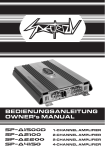
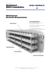
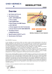
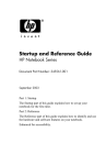
Version: 2015-01-29 Quickstart BACS Installation BACS-System Hardware Components: BACS WEBMANAGER BACS Modules BACS WEBMANAGER BUDGET External + BACS BUS CONVERTER BACS WEBMANAGER BUDGET Slot version + BACS BUS CONVERTER BACS WEBMANAGER BUDGET_III (with integrated BACS BUS CONVERTER) BACS Measuring Cables BACS Bus Cables BACS SPLITTING BOX GENEREX Systems Computervertriebsgesellschaft mbH - www.generex.de - 1 GENEREX Systems Inc. - www.generex.us Overview General Safety Precautions - Working with Batteries Warning and Safety Indication – BACS Safety Precautions Safety – BACS® Configuration and Installation 1. 1.1. 1.2. 1.3. 1.4. 1.5. Installation BACS Hardware Installation and cleaning of the batteries Installation BACS Measuring Cables Installation BACS Modules and Temperature Sensors Installation BACS Bus Cables Connection cable between BACS BUS CONVERTER & BACS WEBMANAGER 2. 2.1. 2.2. 2.3. 2.3.1. 2.3.2. 2.3.3. 2.3.4. 2.4. 2.4.1. 2.4.2. 2.5. 2.6. BACS Module Configuration BACS II Programmer Tool Buscabling Check - Line Check Addressing the BACS Modules Automatic Mode Manual Mode Module Search Scanning Module Address BACS SETUP PAGE for Addressing the BACS Modules Addressing BACS Modules via Automatic Mode Addressing BACS Modules via Manual Mode Expert Mode BACS Reader Tool 3. 3.1. 3.1.1. 3.1.2. 3.1.3 3.1.4. 3.1.5. 3.1.6. 3.1.7. BACS WEBMANAGER Configuration Setup and Network Configuration Installation/Network-Integration of the BACS WEBMANAGER Switch to Operation Mode Network Configuration of the IP-Adress Connection via HTTP and Login Connection of the UPS or other devices Enter Battery Information Network Configuration of the BACS WEBMANAGER 4. Starting BACS for the first time GENEREX Systems Computervertriebsgesellschaft mbH - www.generex.de GENEREX Systems Inc. - www.generex.us 2 General Safety Precautions - Working with Batteries Improper use of the products described in this manual may lead to personal injury and/or property damage. GENEREX is not liable for injuries or damages that result from improper handling these products. Risks associated with improper use include: explosion, fire, and short circuits. Attention! Battery terminals are always live, so never place metal objects or tools on top of the batteries. Battery electrolyte solutions are highly corrosive. Should you observe leaks of electrolyte from a battery, be aware that these fluids are harmful to both eyes and skin. Installation, maintenance, and repair of batteries and battery equipment should be performed only by trained specialists (or personnel authorized by battery manufacturers to perform such services). Persons who have not been trained in battery safety or the proper handling of batteries (or who have not been authorized to work on them) must not handle batteries. Observe the following regulations (IEEE standards USA only): 1. 2. 3. 4. 5. 6. 7. 8. 9. ZVEI publication "Instructions for the Safe Handling of Electrolyte for Lead-acid Accumulators." ZVEI publication "Safety Data Sheet on Accumulator Acid (Diluted Sulfu-ric Acid)." VDE 0510 Part 2: 2001-12, in accordance with EN 50272-2:2001: "Safety Requirements for Secondary Batteries and Battery Installations - Part 2: Stationary Batteries". IEEE Standard 450-2002: "Recommended Practice for Maintenance, Testing and Replacement of Vented Lead Acid Batteries for Stationary Appli-cation." IEEE Standard 1375-1998: "Guide for Protection of Stationary Battery Systems Observe also the following safety rules: Ensure that all electrical loads and power supplies/charging devices (including separators, fuses, and switches) are switched off. This must be carried out by qualified personnel. Remove all wrist watches, rings, chains, jewelry and other metal objects before working with batteries. Use insulated tools only. Wear insulating rubber gloves and rubber shoes. Never place tools or metal components on top of the batteries. Make sure that the battery or batteries are not mistakenly grounded. (The consequences of an accidental or incorrect connec-tion can be mitigated reduced by terminating the ground connection.) If the system is grounded, terminate the connection. Touching a grounded battery by mistake can result in severe electric shock. Before establishing connections, make sure to verify polarity. (Better one too many times than one too few.) Filled lead-acid batteries contain highly explosive gas (hydrogen/air mixture). Never smoke, handle open flames or create sparks near the batteries. Always avoid electrostatic discharge; wear cotton clothing and ground yourself if necessary. Wear the appropriate safety clothing and equipment. For further information refer to the battery makers instructions for installation, maintenance, and operation of their battery products. GENEREX Systems Computervertriebsgesellschaft mbH - www.generex.de - 3 GENEREX Systems Inc. - www.generex.us Warning and Safety Indication – BACS Safety Precautions Attention HIGH VOLTAGE WARNING Do not open the BACS® sensor modules. Do not attach any kind of objects to the battery or the BACS® modules itself apart from the connecting cables! The BACS® modules and cables could be live! MAGNETIC EMISSIONS Do not put any materials or equipment sensitive to magnetic emissions near the BACS® WEBMANAGER (For example, monitors, disk drives, memory chips or magnetic tapes.) INSTALLATION BY QUALIFIED PERSONNEL ONLY! ! The BACS® installation should only be installed by qualified personnel. BACS® is installed on batteries where high voltages could cause injuries or even death if not handled properly! The BACS® connection cables (temperature cable, bus cable, measuring cable) could be live! To avoid short circuits, do not touch, replace, or cut BACS® cables, before having disconnected the system from the batteries! WARNING! BACS® modules must NOT be mounted on a damaged battery! If a battery is damaged and its internal resistance is high, charging current (or current being discharged) may follow the path of least resistance and flow through the BACS® module, not the battery. Overheating and destruction of the BACS® module can result from this. For this reason, never use batteries that are damaged or show high internal resistances CHECK MODULES DURING INSTALLATION AND INITIAL CHARGING The GENEREX service technician should monitor the BACS® modules and the initial charge during the installation. Excessive heat created by the BACS® may be indication of a damaged battery or incorrectly mounted cables. The installer should not leave the installation site before installation of the BACS® system is complete and the battery has had 60 minutes to charge. Once this has taken place, if the BACS® system shows stable voltages and normal internal resistance values, it may be considered safe and can be monitored remotely. Observe battery temperature for up to 12 hours after a discharge period Observe battery temperature for up to 12 hours after a discharge period! For VRLA batteries, the risk of thermal runaways is greatly elevated during the 12 hours following discharge. Rising temperatures in damaged battery cells and blocs can cause fire. React immediately if battery cell or bloc temperatures rise after a discharge phase. GENEREX Systems Computervertriebsgesellschaft mbH - www.generex.de GENEREX Systems Inc. - www.generex.us 4 Safety – BACS® Configuration and Installation AVOID INSTALLATIONS IN CERTAIN AREAS Do not install BACS® in the following areas: Wet or dusty places, or rooms that are not protected from water or high humidity Areas with a constantly high concentration of salted or oxidizing gases Areas close to sources of extreme heat, open flames, or sparks, or having high variations in temperature Areas prone to physical vibrations Areas with high gas concentration or flammable materials MONITORING SYSTEM - MONITORING AND ALARMS BACS® is a monitoring system and should be used accordingly. Ensure proper setting of the alarm threshold and proper time frame for reaction to alarms! BACS® is a tool designed to increase the durability of accumulators, but its most important function is to monitor the battery in order to avoid breakdowns. For this reason, it is recommended that situations that trigger alarms be attended to within two hours of alarm notification. BACS® may not be able to eliminate altogether the risk of battery or charger failures, but through its advance warning system and patented Equalization process, it gives the user the ability to prevent the issues that can result from such failures Never mix and match different BACS® C Module versions or BACS® Measuring cable types! (For example: using BACS® C Modules with REV 2 and 3 on the same battery system, using BACS® BC2 and BC5 cables in the same battery system.) This practice can damage modules and lead to inaccurate measurements. For questions and comments refer to: www.generex.de or [email protected] GENEREX Systems Computervertriebsgesellschaft mbH - www.generex.de - 5 GENEREX Systems Inc. - www.generex.us 1. Quickstart - Installation BACS Hardware The installation of BACS consits of 4 major steps. The most important steps are described in this „Quickstart“ as follows. (Please refer to the BACS® User Manual und BACS® Viewer Software manual for further information.) 1.1. Installation and cleaning of the batteries 1. Cleaning the surface to get an optimal fixing of the BACS Velcro glued surface. 2. Use only cleanser, which are recommended from the battery manufacturer. 3. If you are unsure, use simply soapy water and clean and dry the surface carefully. 1.2. Installation BACS Measuring Cables 1. Assemble the supply and measuring cables type BCxxxx on the battery terminals. 2. The ringterminal should be mounted nearly the battery pole, but above the battery connecting bridge (please take a look at drawings below). 3. Pay attention to the correct polarity: red cable to Order No.: BC5xx plus pole (+), black cable to the minus pole (-). 4. Tighten the terminal and monitoring screws to the torque which is recommended by the battery manufacturer. Order No.: BC4axx GENEREX Systems Computervertriebsgesellschaft mbH - www.generex.de GENEREX Systems Inc. - www.generex.us 6 Connection of the BACS Measuring Cables 6V – 16V battery + BC5 measuring cable 1.2V-2V battery with 2 poles BC4a/b measuring cable + GENEREX Systems Computervertriebsgesellschaft mbH - www.generex.de - 7 GENEREX Systems Inc. - www.generex.us 1.2V-2V battery with 4 or more poles + BC4a/b measuring cable Finished the installation of the BC4x measuring cables! Finished the installation of the BC5x measuring cables! GENEREX Systems Computervertriebsgesellschaft mbH - www.generex.de GENEREX Systems Inc. - www.generex.us 8 1.3. Installation BACS Modules and (optional) Temperature Sensors BACS Module REV.3 with integrated temperature sensor (standard) BACS Module REV.3 optional available with external temperature sensor Order No.: BACSC20 BACSC23 BACSC30 BACSC40 1. Module bottom side: a) Remove lower part of Velcro b) Remove the foil from the lower part 2. Mount the lower Velcro on the battery surface: Keep pressure at least for 5 seconds! 3. Module bottom side: Remove the foil of the temperature sensor 4. Optional external temperature sensor: Remove the foil of the external temperature sensor GENEREX Systems Computervertriebsgesellschaft mbH - www.generex.de - 9 GENEREX Systems Inc. - www.generex.us Connecting BCx Measuring Cable to the BACS Module 1. Connect the BACS measuring cable to the rear port of the BACS module. 2. Put the connector of the measuring cable into the plug till the limit stop. Remember the right position, the connector has a reverse voltage protection! 3. Push the BACS module on the already fixed Velcro on the battery. Finshed the installation of the BACS modules and measuring cables! GENEREX Systems Computervertriebsgesellschaft mbH - www.generex.de GENEREX Systems Inc. - www.generex.us 10 Important information before installing the BACS Module! 1. Do not install the BACS modules on cooling fins or cell vent plugs! 2. At wet– or maintenance-free cells, please keep a distance of at least 10cm to the cell vent plugs! 10 cm 3. If there‘s not enough space to mount the BACS module on the top of the battery, it‘s also possible to mount it on the front side. 4. BACS module with external temperature sensor (optional) For BACS modules REV.3.xx, an external temperature sensor is available. This sensor will be mounted on the end of a 23cm = 9 in. long cable. This sensor could be already mounted or delivered for self installation. The sensor will be mounted on the surface of the battery (at all batteries on the same position)! GENEREX Systems Computervertriebsgesellschaft mbH - www.generex.de - 11 GENEREX Systems Inc. - www.generex.us 1.4. Installation BACS Bus Cables „side by side“: Order No.: B2BCRJXX The BACS bus cable are special made components (twisted cable, special coat). If other cables will be use, the function of the system could not be warranted. To avoid needless cable length, the bus cable are available in different length. 1a Important features for correct function: 1. The maximum cable length between the last module and the BACS WEBMANAGER may not be longer more than 60 m = 2364 in. (also by using a SPLITTING BOX). 2. Don‘t connect more than 60 modules at one bus string. 1b 3. The modules could be connected in any sequential arrangement to the bus. It‘s not required to connect the modules by adresses. „behind“: 4. To get a higher safeguarding against failure, the bus cabling should be done as loop. If there‘s one interruption, the communication is still warranted. 5. For the loop cabling the last module has to be connected to the second bus port of the BACS BUS CONVERTER or BACS WEBMANAGER BUDGET III. (Section 1.5.) 2a 2b „among each other“: 3 Finished the installation of BACS C modules, measuring and bus cables! GENEREX Systems Computervertriebsgesellschaft mbH - www.generex.de GENEREX Systems Inc. - www.generex.us 12 1.5. Connection cable between BACS BUS CONVERTER & BACS WEBMANAGER The BACS WEBMANAGER BACS WEBMANAGER BUDGET_III with integrated Bus Converter Order No.: BACSKIT_BIII BACS WEBMANAGER BUDGET external + external BACS BUS CONVERTER Order No.: BACSKIT_B 6-pole special cable RJ12 (ca. 1m = 39 in.) BACS WEBMANAGER BUDGET Slot + external BACS BUS CONVERTER Order No.: BACSKIT_BSC 6-pole special cable RJ12 (ca. 1m = 39 in.) Attention! Do not connect any BACS® bus cable type labeled B2BCRJxxx to the COM3/AUX port of the BACS® WEBMANAGER BUDGET I! This port is designed for the use with the original 6-pin cable, which comes with every BACS® Bus Converter. The connection of any other cable to this port can damage the contacts and cause addressing and communications problems. The BACS® WEBMANAGER BUDGET COM3/AUX port comes sealed and labeled for precisely this reason! (The label should be removed before connecting the proper cable.) BACS WEBMANAGER BUDGET, COM3/AUX Port Warning Label The BACS BUS CONVERTER The BACS BUS CONVERTER provide the galvanic isolation between the battery bus and the BACS WEBMANAGER. Additionally the BACS BUS CONVERTER filter EMI and the BACS bus protocol will be convert to RS232 protocol. The activ EMI filter in the BACS BUS CONVERTER needs a stabilized and uninterrupted 12VDC power supply, which is included the shipment. Order No.: BUS_CONV_V GENEREX Systems Computervertriebsgesellschaft mbH - www.generex.de - 13 GENEREX Systems Inc. - www.generex.us Connection of the BACS WEBMANAGER BACS WEBMANAGER BUDGET III with integrated BUS CONVERTER BACS Bus Cable Power Supply BACS Bus Cable BACS BUS BACS WEBMANAGER BUDGET external with additionally BACS BUS CONVERTER BACS Bus Cable BACS BUS Power Supply Power Supply COM3/AUX Special Cable RJ12 GENEREX Systems Computervertriebsgesellschaft mbH - www.generex.de GENEREX Systems Inc. - www.generex.us 14 COM3/AUX BACS WEBMANAGER BUDGET Slot with additionally BACS BUS CONVERTER For usage with a UPS, inverter or other device with compatible slot. BACS Bus Cable Power Supply BACS BUS COM3/AUX Special Cable RJ12 GENEREX Systems Computervertriebsgesellschaft mbH - www.generex.de - 15 GENEREX Systems Inc. - www.generex.us COM3/AUX The BACS SPLITTING BOX OPTION : For systems with more than 60 batteries we recommend to use BACS SPLITTING BOX. With the BACS SPLITTING BOX the total bus cable length could be reduced and it allows a star layout of the bus cabling for an optimized installation. Order No.: BCII_SPLITT Connection Diagramm BACS SPLITTING BOX - BACS BUS CONVERTER – BACS WEBMANAGER BUDGET BACS Bus Cable Attention: Equal distribution of all BACS modules to the ports of the SPLITTING BOX! Maximum 60 BACS modules pro port! BACS Bus Cable BACS BUS Power Supply BACS BUS Power Supply BACS BUS COM3/AUX Special Cable RJ12 GENEREX Systems Computervertriebsgesellschaft mbH - www.generex.de GENEREX Systems Inc. - www.generex.us 16 COM3/AUX Connection Diagramm BACS SPLITTING BOX - BACS WEBMANAGER III BACS Bus Cable BACS Bus Cable Power Supply BACS BUS BACS BUS BACS BUS Finished installation of the BACS Hardware! At this point of time, the BACS modules are not functional! GENEREX Systems Computervertriebsgesellschaft mbH - www.generex.de - 17 GENEREX Systems Inc. - www.generex.us 2. Quickstart - BACS Module Configuration Programmer button for addressing the module Module LED for status notification LED Notification Special pen to press the programmer button Operation state module: LED notification: Not addressed (default delivery status) red blinking Programming modus activ fast red blinking Programmed & communication activ green statically Programmed & no activ communication green blinking Threshold overtravel/underrun red statically Search mode red / green alternating BACS Modules are available in following conditions: 1. Default delivery status not addressed There are two options to address the BACS modules: Status notification of the module LED: slowly red blinking! Standard address = 0 A) Via «BACS II Programmer Tool » = recommended! BEFORE starting the addressing, ALL modules have to be in this condition! If this is not the case, all modules have to be reset back into the status of delivery. Take a look at page 23. 2. Pre-Programmed by the supplier optional service - Order No. „BACS_PGM” Status notification of the module LED: Slowly green blinking! = no BACS communication or Statically green light! = normal operation Hinweis: At pre-adressed modules go on with section 3! - Software installation (Section 2.1.) - BACS cabling check (Section 2.2.) - Module addressing (Section 2.3.) B) Via BACS WEBMANAGER «Setup page» (Section 2.4.) Information: „Sleep Mode“ Status notification of the module LED: no activity Modules > Rev 3.xx are in «sleep mode» when they will be connect to the measuring cable. They wake up automatically, if the BACS WEBMANAGER, BACS Programmer or BACS Reader sends request. To wake up the modules, it‘s necessary to activate bus communication via connected BACS WEBMANAGER, BACS Programmer or BACS Reader. GENEREX Systems Computervertriebsgesellschaft mbH - www.generex.de GENEREX Systems Inc. - www.generex.us 18 2.1. BACS II Programmer Tool The BACS II Programmer Software is a Windows software, which can be used for the addressing and checking the BACS modules. Installation via BACS WEBMANAGER BUDGET III 1. Download and install the actually “BACS_Programmer“ Version 1.18 from the following link (BACS Utilities): The BACS modules could be addressed via notebook before the installation or directly on site. Addressing via BACS WEBMANAGER is not necessary. http://www.generex.de/download/bacs/windows/ cdimg/bacscd.zip BACS Service Port RS232-Port 2. Connect the „BACS WEBMANAGER BUDGET III“ via „Service Port“ to the RS232-port of your notebook. 3. Connect the BACS modules to the BACS bus ports of the „BACS WEBMANAGER BUDGET III“. BACS BUS BACS BUS Power Supply 4. Power up the „BACS WEBMANAGER BUDGET III“ via delivered power supply. 5. Start the actually “BACS_Programmer“, choose and „Open“ the „COM-Port“, which is connected to the „BACS WEBMNAGER BUDGET III“ GENEREX Systems Computervertriebsgesellschaft mbH - www.generex.de - 19 GENEREX Systems Inc. - www.generex.us Programming via BACS WEBMANAGER BUDGET and BACS BUS CONVERTER 1. Download and install the actually http://www.generex.de/download/bacs/windows/ cdimg/bacscd.zip “BACS_Programmer“ Version 1.18 from the following link (BACS Utilities): 2. Disconnect the special RJ12-cable between „BACS BUS_CONVERTER“ and COM3/AUX port of the “BACS WEBMANAGER_BUDGET“ . 3. Connect the RS232-Port of your notebook, via delivered RS232-cable, with the RS232-port of the “BACS BUS CONVERTER“. RS232-Port BACS BUS BACS BUS 4. Connect the BACS modules to the BACS bus ports of the “BACS BUS CONVERTERs“. Power Supply 5. Power up the „BACS BUS CONVERTER“ via delivered power supply. 6. Start the actually “BACS_Programmer“, choose and „Open“ the „COM-Port“, which is connected to the „BACS BUS CONVERTER“. GENEREX Systems Computervertriebsgesellschaft mbH - www.generex.de GENEREX Systems Inc. - www.generex.us 20 2.2. Buscabling Check - Line Check (BACS II Programmer >= Version 1.16) With the Line Check it’s possible to analyze the bus cabling quickly. If there are breaks or contact problems, with the Line Check it’s possible to find the fault position fast. If the Line Check will be used, the bus cabling has to be star layouted and if there are more than one bus string present, it has to be tested every bus string separately. You could solve the failure during the running Line Check and if it’s solved successfully, you’ll see it immediately. If the bus cabling is done as loop, it’s necessary to open the loop at the beginning or end at during the Line Check modus. The Line Check can be done only, if all modules are in default status with address 0. The Line Check provide two mode: “Send Line“ and “Receive Line“: 1. Send Line Both send lines (TX: pin 1+2) will be check 1. Start the actually „BACS_Programmer“. 2. Choose the button „Line Check“. 3. Choose the modus „Send Line“. 4. Press the „Start“-Button. 5. The connection is o.k., if all, to this bus string connected modules, are alternately Red / green flashing. 6. If this is not the case, you have to search for a failure at the first module which is not flashing, respectively ones before. GENEREX Systems Computervertriebsgesellschaft mbH - www.generex.de - 21 GENEREX Systems Inc. - www.generex.us 2. Receive Line Both receive lines (RX: pin 3+4) will be check 1. Start the actually „BACS_Programmer. 2. Choose the button „Line Check“. 3. Choose the modus „Receive Line“. 4. Disconnect the last module from the measuring cable, which is connected at the end of the busstring. 5. Press the address button on the module during the reconnection to measuring cable. 6. Press the „Start“-Button. 7. Now the counter should count down, beginning with 300. If this is the case, all connections are ok. You don’t have to wait until the counter reach the “0”, it’s enough when it counts down for 10-15 times. 8. If the counter don’t count down, there’s a fault position in the bus cabling. Detecting the fault position: Retry the test with a module, which is connected in the middle of the bus string. If the counter counts down now, the fault position is between the middle and the last module in the bus string and you have to retry the test in this area until you find the fault position. If the counter don’t counts down now, the fault position is between the first and the middle modul in the bus string and you have to retry the test in this area until you find the fault position. Please remember that also several faulty positions are possible. GENEREX Systems Computervertriebsgesellschaft mbH - www.generex.de GENEREX Systems Inc. - www.generex.us 22 2.3. Addressing of the BACS Modules Two modes are available: a) Automatic Mode - addresses will be set automatically b) Manual Mode - addresses will be set manual (Section 2.3.1.) (Section 2.3.2.) 2.3.1. Automatic Mode The addresses will be set automatically! 1. Choose the button „Automatic Mode“. 2. Enter „Start Address“ and „End Address“. It‘s also possible to program partial address ranges, to program the addresses in sections (e.g. first adress 1-32, then adresse 33-64, etc.). 3. Press the button „Start“ . Attention: If there‘s an error during the automatic mode, an error message will be shown and the automatic mode should be start again. Either from the beginning, after reset all modules to address „0“, or from the module before the error occurs. Example for an error on module „5“: A) Press button on the module „5“ for 10 seconds to set it to adress „0“ B) Restart the automatic mode C) Enter „5“ as start address D) Follow the instruction of the Programmer Tooll Set all addresses to „0“: If you enable the check box in the Automatic menu „Set all addresses to 0“ , all modules will be set in the default delivery condition (address „0“). Status notification of the module LEDs: slowly red blinking! GENEREX Systems Computervertriebsgesellschaft mbH - www.generex.de - 23 GENEREX Systems Inc. - www.generex.us 2.3.2. Manual Mode The addresses will be set manually! 1. Choose the button „Manual Mode“. 2. Enter the actually module address in the box „Current Address“ and in the box „New Address“ the new desired address. 3. Press the buttton „Set“. The address of the module will change and additionally shown in the display of the SW. 2.3.3. Module Search 1. With the function „Modul Search“ it‘s possible to find a module. 2. The wanted module will signalize it via the status notification of the module LED: red / green alternate! 3. By pressing the button on the module or pressing the stop button, it will be switch back to normal operation mode. Attention: : As long as the module search is not finished via buttons, the module will not answer the requests from the programmer tool or rather the BACS II Webmanager! 2.3.4. Scanning Module Address BACS BUS BACS BUS 1. Connect the accordant module via the bus cable to the BACS BUS CONVERTER/BACS WEBMANGER BUDGET III directly. Attention: Connect only one module to the bus! 2. Choose the function „Address Search“. 3. Press the„Start“ Button. The address will be shown in the display of the SW. GENEREX Systems Computervertriebsgesellschaft mbH - www.generex.de GENEREX Systems Inc. - www.generex.us 24 2.4. BACS SETUP PAGE for Addressing the BACS Modules 1. Click on „BACS Configuration“ in the configuration menu. 2. Click on button “To setup page”. 3. Click “Enable”. This will interrupt the operation mode of the BACS system. The polling and initialize of the modules will stop. The setup page provides the features for addressing the BACS modules. There are two options for the configuration: a) Automatic Mode - addresses will set automatically (Section 2.4.1) b) Manual Mode - single addresses will be set (Section 2.4.2.) 2.4.1. Addressing BACS Modules via Automatic Mode Addresses will be set automatically! 1. Press “Automatic Mode“ . GENEREX Systems Computervertriebsgesellschaft mbH - www.generex.de - 25 GENEREX Systems Inc. - www.generex.us 2. Enter „Start Address“ and „End Address“. Example: If you have 64 batteries, enter 1 for Start Address and 64 for End Address. It‘s also possible to program partial address ranges, to program the addresses in sections (e.g. first address 1-32, then adresse 33-64, etc.). 3. Press “Start”. 4. Addressing modus will start. ALL module status notification LEDs change from slowly red blinking to fast red blinking! Attention: If not all modules are fast red blinking, please take a look at section 2.3.1. „reset to factory settings“ 5. Press the programmer button on the module for a short time and the addressing will confirmed. Status notification of the module LEDs green = Adressing sucessfully! Start with the module 1 and go on until you addressed the last module. 6. Click the button “Stop”. The system will stop the addressing procedure. 7. The addressing was sucessfull, if all status notification of the Module LEDs are green lighting or green blinking! GENEREX Systems Computervertriebsgesellschaft mbH - www.generex.de GENEREX Systems Inc. - www.generex.us 26 2.4.2. Addressing BACS Modules via Manual Mode The module address will set individual! 1. Choose the button „Manual Mode“. 2. Enter the actually module address in the box „Current Address“ and in the box „New Address“ the new desired address. 3. Press the buttton „Set“. The address of the module will change and additionally shown in the display of the SW. 4. Press the button „Disable“. The operation mode will reactivated. The polling and initialize start is again and the BACS system start up. Tip: Automatic Mode, partial addressing Sometimes it‘s necessary to address the BACS modules step-by-step. Example: First the adresses from 1 till 32 and later from 33 till 64. If an error occurs during the automatic mode, a message will be displayed. Then it‘s necessary to restart the addressing, starting from the module on, where the error occours. It‘s possible to correct the address via „Manual Mode“. 5. Finish: By executing the „Save, Exit & Reboot „ function at the menu «Save Configuration», the BACS values will be measured the first time. GENEREX Systems Computervertriebsgesellschaft mbH - www.generex.de - 27 GENEREX Systems Inc. - www.generex.us 2.5. Expert Mode (from version 1.07) This mode is the optimal fitting for the pre-addressing of the modules 1. You can start the BACS II Programmer Software into the „Expert Mode“ with the command: bacs_programmer.exe –e . 2. During the manually addressing (Manual Mode), the next address will be started, if the last addressing was successful. The box „Modul Values“ will be started automatically too and the message boxes will be disabled. 3. You can open the box „Modul Values“ via the „Values“ button, to get the current measurement values additionally. The values will be automatically polled, if the addressing was succesful. From the module firmware 2.1.x it is required to start the modules first, before to get them out of the „Sleep Mode“. The Programmer sends a „Wake Signal“, will wait for 2 seconds and will then address the module (in Manual Mode only). GENEREX Systems Computervertriebsgesellschaft mbH - www.generex.de GENEREX Systems Inc. - www.generex.us 28 2.6. BACS Reader Tool With the “BACS_II_Reader_Tool” you have the possibility to read the battery data and BACS module parameters directly via RS232 connection. You can read the following data and parameters: battery voltage, battery temperature, battery resistance, module type, module software revision and module hardware revision. Installation via BACS WEBMANAGER BUDGET III 1. Download the actually “BACS_Reader“ version from the following link: Especially at the time of beginning the BACS operation you have so the possibility of a fast control and overview of all important battery measurements and module parameters. The addressing of the BACS modules must be done with the “BACS_Programmer” tool before! http://www.generex.de/download/bacs/windows/ cdimg/bacscd.zip BACS Service Port RS232-Port 2. Connect the „BACS WEBMANAGER BUDGET III“ via „Service Port“ to the RS232-port of your notebook. BACS BUS 3. Connect the BACS modules to the BACS bus ports of the „BACS WEBMANAGER BUDGET III“. BACS BUS Power Supply 4. „Power up the „BACS BUS CONVERTER“ via delivered power supply. Continue with step 6 on page 31! GENEREX Systems Computervertriebsgesellschaft mbH - www.generex.de - 29 GENEREX Systems Inc. - www.generex.us Procedure via BACS WEBMANAGER BUDGET and BACS BUS CONVERTER 1. Download the actually “BACS_Reader“ version from the following link: http://www.generex.de/download/bacs/windows/ cdimg/bacscd.zip 2. Disconnect the special RJ12-cable between „BACS BUS CONVERTER“ and COM3/AUX port of the “BACS WEBMANAGER_BUDGET“ . 3. Connect the RS232-Port of your notebook, via delivered RS232-cable, with the RS232-port of the “BACS BUS CONVERTER“. RS232-Port BACS BUS BACS BUS 4. Connect the BACS modules to the BACS bus port of the “BACS BUS CONVERTER“. Power Supply 5. Power up the „BACS BUS CONVERTER“ via delivered power supply. GENEREX Systems Computervertriebsgesellschaft mbH - www.generex.de GENEREX Systems Inc. - www.generex.us 30 6. Start the actually “BACS_Reader. „Open“ the „COM-Port“, which is connected via „BACS BUS CONVERTER“ or „BACS WEBMANGER BUDGET Typ III“. 7. Selection “Scan Mode”: With this mode you could make automatic request of a complete address range or sub address range. 8. Choose the “Start Address” and “End Address” of the connected BACS modules which you want to readout (Address range must be between 1-340). 9. Choose the “Pollrate” of the request . 10. If the check box “Clear old values at start“ is activated the values will be cleared after restarting the request, otherwise the old values will be overwritten. GENEREX Systems Computervertriebsgesellschaft mbH - www.generex.de - 31 GENEREX Systems Inc. - www.generex.us 11. If the check box “Next impedance measurement in xx minutes“ is activated the resistance will be measured after starting and lapse the time. Note: The impedance can be measured only every 15 min., within this time the showing value is the old measured value of the BACS CXX module memory. Tip: Shortly disconnecting and reconnecting of the BACS measuring cable from the BACS CXX module allows to measure the impedance immediately. 12. Click on the desired link and the module “Sub Screen” will open in a new window to show the values. 13. To start the “Scan Mode“ press the button “Start”. 14. To stop the “Scan Mode“ press the button ”Stop“. 15. Selection “Manual Mode”: With this mode you can make single requests of the connected BACS modules. The values will be shown in an extra window which will open automatically . GENEREX Systems Computervertriebsgesellschaft mbH - www.generex.de GENEREX Systems Inc. - www.generex.us 32 16. Insert the address of the BACS module which you want read in the “Address“ field (Address range must be between 0-340). 17. If you press the button of the desired value it will be shown in the field of the extra window. 18. With the function “Modul Search“ you have the possibility to find modules. For this insert the module “Address” in the field and press the button ”Set”. The LED on the module will now blink alternate red and green! Acknowledged the “Modul Search“ via click on the button “Reset” or pressing the switch on the module directly . 19. The requests and answer will be shown by colored LED‘s. If the answer is faulty the counter counts up. Press the button “Reset“ to reset the counter. 20. To end the „BACS_II_Reader_Tool“ close the COM port via pressing the button “Close“ and then ”Quit”. GENEREX Systems Computervertriebsgesellschaft mbH - www.generex.de - 33 GENEREX Systems Inc. - www.generex.us 3. Quickstart - BACS WEBMANAGER Configuration BACS WEBMANAGER BUDGET Slot 7 3 BACS WEBMANAGER BUDGET 7 3 2 6 2 1 7 4 3 6 BACS WEBMANAGER BUDGET III 2 6 5 9 8 1 5 1 Alarm Contact Description Function 1 COM1 Port Connection with an UPS or another end device via a RS232-cable. 2 COM2 Port Connection for optional devices like a modem, multi sensor SENSORMANAGER, temperature sensor, humidity, field busses (MODBUS, RS232, Profibus, LONBus, etc.). 3 LAN Port Ethernet 10/100 Mbit interface with integrated LEDs (green LED: connection to the network established, yellow LED: network-activity). 4 DC Input Power supply 12VDC/1A stabilized through external power supply, DC-connector inside (-) minus, outside (+) plus. 5 COM3/AUX For the connection to the BACS® CONVERTER (at BUDGET II/III internal), max.1m Rj12/6pole cable. 6 LEDs (red / green) Operation Status BACS WEBMANAGER LED Notification Start procedure 1, uploading of the OS red blinking Start procedure 2, booting of the OS red long on If the red and green LED shine at your BACS Webmanager during the red and green reboot, large broadcast traffic is present on your network „receive buffer during overflow“. The green LED is signalizing at the reboot, that the „traffic buf- the booting fer“ is full. Advice: You should filter broadcasts via your switch, because it comes to performance losing of the BACS Webmanager unnecessary. 7 DIP Switch 11 Normal operation green blinking UPS communication lost red blinking For the switch between configuration mode and normal mode . 1 + 2 position OFF : BACS® WEBMANAGER BUDGET in configuration mode and activated IP adress « 10.10.10.10. » after coldboot. . 1 + 2 position ON : Automatically IP addressing. DHCP is activated and IP adress will assigned automatically after coldboot. Check the MAC address of the BACS WEBMANAGER, to find the assigned IP address in the DHCP server table. . 1 position ON + 2 position OFF: Normal operation mode. Configured IP adress will be activated after coldboot. 8 Alarm LED BACS-Alarm LED of the integrated CONVERTER (BUDGET II/III only). 9 MUTE Button Button for the acknowledgement and mute of the horn. Alarm LED changes to yellow. 10 BACS Bus 2 x Rj10 ports for connection to the BACS C-Module / SPLITTINGBOX / BACS_CSXXX / GX_R_AUX devices. 11 BACS Service Port For connection to a PC/Laptop RS232-port, for adressing or readout the BACS modules via BACS_Programmer or BACS_Reader Software directly. GENEREX Systems Computervertriebsgesellschaft mbH - www.generex.de GENEREX Systems Inc. - www.generex.us 34 4 3.1 Setup and Network Configuration of the BACS WEBMANAGER 3.1.1 Installation/Network-Integration of the BACS® WEBMANAGER There are 2 options to network connection 1. Power up the BACS WEBMANAGER via power Power Supply supply. IP 10.10.10.10 DIP-Switch 1+2 = off 2A. Connect the BACS WEBMANAGER directly via network cable/cross cable to the notebook/PC. IP 10.10.10.11 Gateway 10.10.10.10 A network cross cable is a PC to PC network cable and needs no switch or hub between 2 network devices. Attention: For the installation we recommend the following network-configuration: Connect the notebool/PC via cross cable and configure the IP address of the notebook/PC to a address of the same network segment like the BACS WEBMANAGER, e.g.: „10.10.10.11“ AND Gateway 10.10.10.10 Ethernet cross cable IP 10.10.10.10 DIP-Switch 1+2 = off 2B. Connect the BACS WEBMANAGER via switch or hub and 2 ethernet cables to the notebook/PC. Ethernet cable IP 10.10.10.11 Gateway 10.10.10.10 Attention: The BACS WEBMANAGER BUDGET slot (slot card for UPS with SC-slot) will be supplied via internal power supply. This slot card could be connect/disconnect anytime without affecting the UPS function. To interrupt the power supply of the BACS WEBMANAGER, unplug the slot card. GENEREX Systems Computervertriebsgesellschaft mbH - www.generex.de - 35 GENEREX Systems Inc. - www.generex.us 3.1.2. Switch to Operation Mode Power Supply 1. Connect the BACS WEBMANAGER to the power supply and the BACS WEBMANAGER will start ( ca. 5-9 minutes) 2. The BACS WEBMANAGER is reachable via IPaddress: „10.10.10.10“. (DIP Switch 1+2: „off“) 3. To activate the operation mode the DIP Switch 1 has to be switch „on“ and the power supply has to be disconnect for a coldboot. 4. Connect the BACS WEBMANAGER to the power supply and he will start with the configured IP address and is now in operation mode. (Address „10.10.10.10“ is no longer available!) Power Supply 5. By connection to the configured IP address, it‘s possible to configure the device also. 3.1.3. Network Configuration of the IP-Adress 1. Open Command Window 2. Automatically search via „Netfinder“ Tool 1. Open a command prompt window or 2. enter “cmd.exe” in the command prompt 3. Enter the following command: „route add 10.10.10.10 <your local IP address>” (Example: “route add 10.10.10.10 192.168.222.54” ) The following link provides the „Netfinder“ software, which search for devices in your network automatically: http://www.generex.de/generex/download/software/ install/NetFinder.zip 4. Check the connection to the BACS WEBMANAGER via ping („ping 10.10.10.10“). Open the http website to start the configuration. Note: The internal web-server takes a while to get started. Approximate 3 to 5 minutes after the first start of the WEBMANAGER; the UPS status LED should change from static red (boot phase) to green flashing. This indicates that the web-server is ready now. . 3.1.4. Connection via HTTP and Login 1. Open the web browser „MS-Internet-Explorer“ or „Mozilla“. 2. Enter the IP address http://10.10.10.10. The configuration of the BACS WEBMANAGER via web interface is now available. 3. The standard user data for the access are „admin“ for user name and „cs121-snmp“ for the standard password. GENEREX Systems Computervertriebsgesellschaft mbH - www.generex.de GENEREX Systems Inc. - www.generex.us 36 3.1.5. Connection of the UPS or other devices Optional Only if a UPS or other device is connected to COM1 COM 1 1. Connect the UPS via original RS232-serial cable to the COM1-port of the BACS WEBMANAGER. For further information on how to set-up a UPS in the BACS Webmanager, we refer to the CS121 user manual, which is part of this documentation CD ROM or available as download from the UPS or BACS website of your supplier. The CS121 is fully integrated in the BACS WEBMANAGER. All UPS function and the general configuration are descripted in this manual deparately: COM 1 Follow this link to download the actually version of the CS121 manual: CS121 manual 2. Choose „UPS Model & System“ in the configuration menu. 3. Set your „UPS Model“, which is connected to the WEBMANAGER. 4. Click the “Apply” button to confirm your settings. Further informations of the UPS configuration, you will find in the CS121 manual. GENEREX Systems Computervertriebsgesellschaft mbH - www.generex.de - 37 GENEREX Systems Inc. - www.generex.us 3.1.6. Enter Battery Information 1. Go to “BACS Configuration” menu. 2. Enter the battery information Example: If you got 64 batteries in 2 strings, please enter 64 into the area “Number of batteries” and 2 into “Number of strings”. UPS with centre tapping / positive and negative strings If the battery system of your UPS is using « centre tapping » (where one string is the positive string and the other string negative string, both strings have their individual charger) than you have to configure your BACS system with at least 2 strings (or more). Explanation: It should be avoided that battery voltage between the 2 strings are not the same due to separate chargers for the positive and negative strings. To assure an ideal Equalisation at different string voltages (+ and – string), it is required to set the amount of strings into the BACS configuration to “2” or higher. By configuring more than 1 string, the BACS configuration will change the Equalisation process to work only within each string. Now every string is handled individually by the BACS system. (Examples: 2 parallel strings -> BACS configuration number of strings =4 3 parallel strings -> BACS configuration number of strings = 6; etc.) The following UPS types are well known to work with 2 strings or more and should not be configured as single string systems: NEWAVE Concept Power Series, AEG Protect Type 3. Modular, Socomec DIGIS, Rittal PMC Extension, INFORM Pyramid DSP. Please refer to your UPS manufacturer for further information about your UPS system if you are unsure how many strings to enter. 3. BACS Status Notification If you tick the box “List Module Numbers String wise”, the BACS STATUS screen will list the address number of the batteries string wise, e.g. At 2 Strings with total 64 batteries you will see at string 1 the addresses 1-32 and at string 2 the addresses 33 -64. 4. If you have enabled the feature “List modules numbers stringwise”, the BACS log file will identify the batteries per string with a text prefix like: “4S2” which means “module 4, string 2”. This makes the identification of the BACS module with an alarm easier for you. The following figure shows the alarm log file of a BACS Webmanager where a temperature alarm was present on several modules, here identified with their string number. GENEREX Systems Computervertriebsgesellschaft mbH - www.generex.de GENEREX Systems Inc. - www.generex.us 38 3.1.7. Network Configuration of the BACS WEBMANAGER Basic Network Configuration 1. Click on „Network & Security“ in the „Configuration“ menu. 2. Enter the local parameter for “Local Address”, “Gateway Address” und “Subnet Mask” (“DNSServer”, if desired). 3. Click on “Apply”, to acknowledge the entry. 4. Click on “Time Server” . 5. Enter the „IP Address“ for the timeserver. The timeserver settings are important. The logging data of events and alarms is derived using the timeserver service. (Note: if the web adapter is not able to reach a timeserver, the default time is 1 January 1970) 6. Changes on each configuration field, has to be acknowledge by pressing the button „Apply“, to save them. 7. Finally, click on “SAVE, EXIT & REBOOT” to save changes permanent and wait until the webbrowser releases the connection to the BACS® WEBMANAGER. (This can take up to 5-9 minutes.) GENEREX Systems Computervertriebsgesellschaft mbH - www.generex.de - 39 GENEREX Systems Inc. - www.generex.us 4. Starting BACS for the first time 1. BACS starting The following start-up screen is visible. Status: BACS Module initialized = Status ok BACS Module not reachable BACS Module still not initialized/polled If BACS has initialized all modules successful, you will see the BACS status page, with voltage and temperature of the batteries, equalisation power and the status LED. After 15 minutes the first measuring results of the impedance is made. Please wait until the first RI measuring is visible before you continue with chapter 4.3 “BACS Module & Alarm Threshold Setting”. Webbrowser BACS status page (6124modules) End of BACS QUICKSTART! For more information and instructions take a look at capitel 4.1 of the BACS user manual and the FAQs. GENEREX Systems Computervertriebsgesellschaft mbH - www.generex.de GENEREX Systems Inc. - www.generex.us 40