1
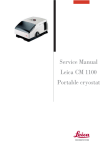
Service Manual
Leica CM3050 S
Cryostat
Revision Record
VERSION
DATE
VERSION
NUMBER
NEW PAGES
December 2000
1.00
First Version
AMENDMENT DETAIL
Service Documentation
Leica CM3050 S
Cryostat
Version 1.0
Produced by:
Leica Microsystems Nussloch GmbH
Postfach 1120
Heidelberger Str. 17-19
D-69222 Nussloch
Phone :
(06224) 143-0
Facsimile : (06224) 143-199
© Leica Microsystems Nussloch GmbH
Table of contents
Inhaltsverzeichnis
Chapter 1
Introduction
Kapitel 1
Einleitung
Chapter 2
Mechanics
Kapitel 2
Mechanik
Chapter 3
Electronic
Kapitel 3
Elektronik
Chapter 4
Cooling System
Kapitel 4
Kühltechnik
Chapter 5
Spare Parts
Kapitel 5
Ersatzteile
Chapter 6
Other
Kapitel 6
Sonstiges
Service Manual / Leica CM3050 S
Version 1.0 12/00 © Leica Microsystems
Page 4
Chapter 1
Introduction
Chapter 1
Kapitel 1
Introduction
Einleitung
Version 1.0
Version 1.0
Service Manual / Leica CM3050 S
Version 1.0 12/00 © Leica Microsystems
Page 1
Chapter 1
Introduction
Table of contents
Inhaltsverzeichnis
1.1
General Information ................................. 4
1.1.1 Dokumentation .............................. 4
1.1.2 Specified use and application.... 5
1.1.3 Ordering Spare Parts ................... 6
1.1.4 Warranty and Service .................. 7
1.2
Saftey instructions ................................... 8
1.2.1 Danger ............................................ 8
1.2.2 Qualified Personnel ...................... 9
1.2.3 Symbols used in the text
and their meanings ...................... 9
1.2.4 Liability ......................................... 10
1.2.5 Instructions .................................. 11
1.2.6 Instrument type ........................... 11
1.2.7 Transport and installation ......... 11
1.3
Instrument-specific information .......... 12
1.3.1 Information on instrument
design and safe handling .......... 12
1.3.2 Integrated safety devices ......... 12
1.3.3 Locking the handwheel ............. 13
1.3.4 Centering the handwheel grip.. 14
1.3.5 Emergency stop function .......... 14
1.3.6 Knife guard .................................. 15
1.3.7 Transport ...................................... 15
1.3.8 Site requirements ....................... 15
1.3.9 Electrical connections ............... 16
1.3.10 Handling microtome
knives/blades. ............................. 16
1.3.11 Knife guard/handwheel lock .... 16
1.3.12 Motorized sectioning ................. 17
1.3.13 Defrosting/Handling frozen
tissue ............................................ 17
1.3.14 Frozen parts of the instrument .....
and frozen accessories ............. 17
1.3.15 Infectious/
radioactive material ................... 18
1.3.16 Disinfection and cleaning ......... 18
1.3.17 Removing/reinstalling the .............
microtome .................................... 19
1.3.18 Display message
‘Dry microtome’........................... 19
Service Manual / Leica CM3050 S
1.1
Allgemeine Informationen ...................... 4
1.1.1 Dokumentation .............................. 4
1.1.2 Bestimmungsgemäße
Verwendung .................................. 5
1.1.3 Bestellen von Ersatzteilen .......... 6
1.1.4 Garantie und Service ................... 7
1.2.
Sicherheitshinweise ................................ 8
1.2.1 Gefahr ............................................. 8
1.2.2 Qualifiziertes Personal ................ 9
1.2.3 Symbole und ihre Bedeutung ..... 9
1.2.4 Haftung ......................................... 10
1.2.5 Gefahrenhinweise ...................... 11
1.2.6 Geräte - Typ ................................. 11
1.2.7 Transport und Aufstellung......... 11
1.3
Gerätespeziefische Informationen ...... 12
1.3.1 Allgemeine
Sicherheitshinweise .................. 12
1.3.2 Eingebaute
Sicherheitssysteme.................... 12
1.3.3 Handradverriegelung ................. 13
1.3.4 Zentrieren des Handradgriffs ... 14
1.3.5 Not-Aus-Funktion ....................... 14
1.3.6 Fingerschutz ................................ 15
1.3.7 Transport ...................................... 15
1.3.8 Standortbedingungen ................ 15
1.3.9 Elektrischer Anschluß ............... 16
1.3.10 Umgang mit Messern ................ 16
1.3.11 Fingerschutz/
Handradverriegelung ................. 16
1.3.12 Motorisches Schneiden ............ 17
1.3.13 Abtauung / Gefrorenes
Probematerial.............................. 17
1.3.14 Kalte Geräteteile ......................... 17
1.3.15 Infektiöses/
radioaktives Material ................. 18
1.3.16 Desinfektion und Reinigung...... 18
1.3.17 Ausbau/Einbau des Mikrotoms 19
1.3.18 Fehlermeldung
‘Trockne Mikrotom’ .................... 19
Version 1.0 12/00 © Leica Microsystems
Page 2
Chapter 1
Introduction
Table of contents
1.3.19
1.3.20
1.3.21
1.3.22
1.3.23
1.3.24
1.3.25
1.3.26
1.3.27
1.1.28
1.3.29
Inhaltsverzeichnis
Maintenance ............................... 20
Site requirements ....................... 20
General site requirements ........ 20
Electrical connections ............... 20
Unpacking and installation ....... 21
Repacking .................................... 21
Standard delivery ....................... 21
Installing the handwheel ........... 23
Inserting the accessories ......... 23
The footswitch ............................ 24
Prior to switching on the ...............
instrument .................................... 25
1.3.30 Overview ...................................... 26
1.3.31 Technical Data ............................ 30
Service Manual / Leica CM3050 S
1.3.19
1.3.20
1.3.21
1.3.22
1.3.23
1.3.24
1.3.25
1.3.26
1.3.27
1.3.28
1.3.29
1.3.30
1.3.31
Wartung........................................ 20
Standortbedingungen ................ 20
Allgemeines ................................. 20
Elektrische Anschlüsse ............. 20
Auspacken und Aufstellen ........ 21
Wiederverpacken ....................... 21
Standardlieferumfang ................ 21
Montage des Handrades .......... 23
Einsetzen des Zubehörs ............ 23
Der Fußschalter .......................... 24
Vor dem Einschalten .................. 25
Gerätegesamtübersicht ............ 28
Technische Daten ....................... 32
Version 1.0 12/00 © Leica Microsystems
Page 3
Chapter 1
Introduction
1.1 General Information
1.1.1 Dokumentation
1.1 Allgemeine Informationen
1.1.1 Dokumentation
The information, numerical data, notes and value
judgments contained in this manual represent the
current state of scientific knowledge and state-ofthe-art technology as we understand it following
thorough investigation in this field. We are under no
obligation to update the present manual periodically
and on an ongoing basis according to the latest
technical developments, nor to provide our
customers with additional copies, updates etc. of
this manual.
Die in der vorliegenden Dokumentation enthaltenen
Informationen, Zahlenangaben, Hinweise und
Werturteile stellen den uns nach gründlicher Recherche bekannt gewordenen derzeitigen Stand
der Wissenschaft und Technik dar. Wir sind nicht
verpflichtet, das vorliegende Handbuch in kontinuierlichen Zeitabständen neuen technischen Entwicklungen anzupassen und Nachlieferungen, Updates usw. dieses Handbuchs an unsere Kunden
nachzureichen.
For erroneous statements, drawings, technical
illustrations etc. contained in this manual we
exclude liability as far as permissible according to
the national legal system applicable in each
individual case. In particular, no liability whatsoever
is accepted for any financial loss or consequential
damage caused by or related to compliance with
statements or other information in this manual.
Für fehlerhafte Angaben, Skizzen, technische Abbildungen usw., die in diesem Handbuch enthalten
sind, ist unsere Haftung im Rahmen der Zulässigkeit
nach den jeweils einschlägigen nationalen Rechtsordnungen ausgeschlossen. Insbesondere besteht
keinerlei Haftung für Vermögensschäden oder sonstige Folgeschäden im Zusammenhang mit der Befolgung von Angaben oder sonstigen Informationen
in diesem Handbuch.
Statements, drawings, illustrations and other
information as regards contents or technical details
of the present manual are not to be considered as
warranted characteristics of our products. These
are determined only by the contract provisions
agreed between ourselves and our customers.
Leica reserves the right to change technical
specifications as well as manufacturing processes
without prior notice. Only in this way is it possible to
continuously improve the technology and
manufacturing techniques used in our products.
This document is protected under copyright laws.
Any copyrights of this document are retained by
Leica Microsystems Nussloch GmbH.
Any reproduction of text and illustrations (or of any
parts thereof) by means of print, photocopy,
microfiche, web cam or other methods – including
any electronic systems and media – requires
express prior permission in writing by Leica
Microsystems Nussloch GmbH.
For the instrument serial number and year of
manufacture, please refer to the name plate at the
back of the instrument.
ã Leica Microsystems Nussloch GmbH
Angaben, Skizzen, Abbildungen und sonstige Informationen inhaltlicher wie technischer Art in der
vorliegenden Bedienungsanleitung gelten nicht als
zugesicherte Eigenschaften unserer Produkte. Insoweit sind allein die vertraglichen Bestimmungen
zwischen uns und unseren Kunden maßgeblich.
Leica behält sich das Recht vor, Änderungen der
technischen Spezifikation sowie des Produktionsprozesses ohne vorherige Ankündigung vorzunehmen. Nur auf diese Weise ist ein kontinuierlicher
technischer wie produktionstechnischer Verbesserungsprozeß möglich.
Die vorliegende Dokumentation ist urheberrechtlich
geschützt. Alle Urheberrechte liegen bei der Leica
Microsystems Nussloch GmbH.
Vervielfältigungen von Text und Abbildungen (auch
von Teilen hiervon) durch Druck, Fotokopie, Microfilm, Web Cam oder andere Verfahren – einschließlich sämtlicher elektronischer Systeme und Medien
– ist nur mit ausdrücklicher vorheriger schriftlicher
Genehmigung von Leica Microsystems Nussloch
GmbH gestattet.
Die Seriennummer sowie das Herstellungsjahr entnehmen Sie bitte dem Typenschild an der Rückseite
des Geräts.
ãÿLeica Microsystems Nussloch GmbH
Service Manual / Leica CM3050 S
Version 1.0 12/00 © Leica Microsystems
Page 4
Chapter 1
Introduction
1.1.2 Specified use and application
1.1.2 BestimmungsgemäßeVerwendung
The Leica CM3050 S is a powerful cryostat for
routine as well as research applications in biology,
medicine and industry.
Der Leica CM3050 S ist ein leistungsfähiger Kryostat
für Routine- und Forschungsanwendungen in der
Biologie, Medizin und Industrie.
The instrument has been designed for rapid freezing
and sectioning of tissue samples.
Das Gerät dient dazu, Probenmaterial schnell zu gefrieren und zu schneiden.
The instrument has not been designed for
unattended storage of tissue material.
Das Gerät ist nicht zur unbeaufsichtigten Lagerung
von Probenmaterial ausgelegt.
The instrument may only be operated within the
scope of its designated use as described above and
as per the instructions given in this manual.
Das Gerät darf nur seiner oben beschriebenen Bestimmung gemäß und nach den Vorgaben in der
vorliegenden Gebrauchsanweisung betrieben werden.
Any other use of the instrument is considered
improper.
Service Manual / Leica CM3050 S
Jeder andere Gebrauch des Gerätes stellt eine unzulässige Betriebsweise dar.
Version 1.0 12/00 © Leica Microsystems
Page 5
Chapter 1
Introduction
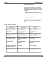
1.1.3 Ordering Spare Parts
1.1.3 Bestellen von Ersatzteilen
To order replacement parts or modules, specify the
following information for each part ordered:
Zum Bestellen von Einzelersatzteilen oder Ersatzteilkomponenten, sind für jede(s) bestellte Teil /
Komponente die folgenden Daten anzugeben:
1. Product model and serial number.
1. Gerätebezeichnung sowie Seriennummer.
2. Leica Part number.
2. Leica-Teilenummer
3. Part description.
3. Teilebeschreibung
4. Quantity required.
4. Gewünschte Teileanzahl
Spare parts can be obtained from your local Leica
office or from:
Ersatzteile können bestellt werden bei Ihrer
Leica-Vertretung vor Ort oder bei:
Leica Microsystems Nussloch GmbH
Leica Microsystems Nussloch GmbH
Postfach 1120
Postfach 1120
Heidelberger Str. 17-19
Heidelberger Str. 17-19
D-69222 Nussloch
D-69222 Nussloch
Germany
Germany
Technical Service - Hotline:
Hotline des Technischen Service:
There are two service hotlines for customer service
and requests.
Zwei Hotline-Nummern für eilige Serviceanfragen
stehen zu Ihrer Verfügung.
Information can be given regarding spare parts,
possibilities for repair, service documentation,
adjustment and alignment requests etc.
Folgende Informationen können über diese Nummern erfragt werden:
Erstzteilinformation, Reparaturmöglichkeiten, Service-Manuals, eilige Fragen zur Justierung einzelner Teile, etc.
( : ++ 6224 143 219
for electronical requests
( : ++ 6224 143 219
Anfragen zu Elektronik
( : ++ 6224 143 219
for mechanical requests
( : ++ 6224 143 219
Anfragen zur Mechanik
Fax:++ 6224 143 219
for electrical and
mechanical requests
Fax: ++ 6224 143 219
Anfragen zu Elektronik,
Kühltechnik, Mechanik
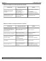
The agencies are obliged to send complete failure
statistics (monthly) to Nussloch for the first year
after instruments have been launched onto the
market. The results and necessary amendments can
be included immediately in the production.
Service Manual / Leica CM3050 S
Die Serviceorganisationen sind gegenüber Leica
Microsystems Nussloch
GmbH verpflichtet, jeweils während des ersten Jahrs nach einer Geräteneueinführung monatlich vollständige Fehlerstatistiken an die Serviceorganisation in Nussloch weiterzuleiten. Dies geschieht, damit notwendige Verbesserungen, die sich aus der Auswertung dieser Statistiken ergeben, unmittelbar in die Produktion einfließen können.
Version 1.0 12/00 © Leica Microsystems
Page 6
Chapter 1
Introduction
1.1.4 Warranty and Service
1.1.4 Garantie und Service
Leica Microsystems Nussloch GmbH guarantees
that the delivered product has been subjected to a
comprehensive quality control procedure based on
our strict in-house testing standards in order to
ensure that the product complies with its technical
specification.
Leica Microsystems Nussloch GmbH steht dafür
ein, daß das gelieferte Produkt einer umfassenden
Qualitätskontrolle nach unseren strengen hausinternen Prüfungsmaßstäben unterzogen wurde, um zu
gewährleisten, daß die technische Spezifikation
eingehalten ist.
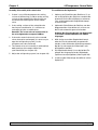
The warranty conditions depend on the contents of
the individual contract concluded, supplemented
by the warranty conditions of your local Leica sales
agency.
Die Gewährleistung richtet sich nach dem Inhalt
des abgeschlossenen Vertrages. Ergänzend gelten
die Garantiebedingungen Ihrer zuständigen LeicaVertriebsgesellschaft.
Any repairs and/or exchange of parts of the product
must be carried out by authorized Leica technical
service engineers. Otherwise, any warranty
becomes invalid and warranty claims can no longer
be made.
Reparaturen am Gerät sowie der Austausch von
Teilen dürfen nur durch von Leica autorisierte Service-Techniker ausgeführt werden. Geschieht dies
nicht, erlöschen Gewährleistungs- und Garantieansprüche.
The local Leica representative or the manufacturer
in Nussloch must be consulted prior to any handling
of or changes to the instrument beyond the scope of
this instruction manual as well as prior to any
modifications or any use of the instrument in
combination with non-Leica components not
expressly authorized by Leica.
Bei jedem Eingriff in das Gerät, bei Modifikationen
oder beim Betrieb in Kombination mit Nicht-LeicaKomponenten, die nicht ausdrücklich von Leica
autorisiert sind, muß die zuständige Leica-Vertretung oder der Hersteller in Nussloch konsultiert
werden.
Spare parts and accessories not supplied by Leica
can under no circumstances be considered as
inspected and/or approved by Leica.
Therefore, installation or use of any such parts may
impair the technical design features and thus
properties of the instrument.
Leica assumes no liability whatsoever for any
damage caused by the use of non-original spare
parts or non-original accessories.
The warranty is only valid and warranty claims can
only be made as long as the instrument has been
operated according to its designated use and
according to the instructions given in this manual.
Improper use of the product and/or faulty operation
invalidate the warranty and any claims based
thereon, and likewise Leica will not assume liability
for any consequential damage.
Service Manual / Leica CM3050 S
Ersatz- und Zubehörteile, die nicht von Leica geliefert wurden, gelten in keinem Falle als von Leica geprüft und freigegeben.
Der Einbau oder die Verwendung solcher Produkte
kann daher konstruktiv vorgegebene Eigenschaften
des Geräts negativ verändern.
Für Schäden, die durch die Verwendung von NichtOriginalteilen oder Nicht-Originalzubehör entstanden sind, ist die Haftung durch Leica ausgeschlossen.
Gewährleistungs- und Garantieansprüche können
nur geltend gemacht werden, wenn das Gerät seinem bestimmungsgemäßen Gebrauch entsprechend und unter Einhaltung der in der vorliegenden
Bedienungsanleitung gegebenen Hinweise betrieben wurde.
Bei unsachgemäßer Handhabung oder Fehlbedienung des Geräts erlöschen Gewährleistungs- und
Garantieansprüche. Für daraus entstandene Schäden übernehmen wir keine Haftung.
Version 1.0 12/00 © Leica Microsystems
Page 7
Chapter 1
Introduction
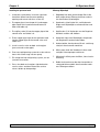
1.2 Saftey instructions
1.2.1 Danger
1.2. Sicherheitshinweise
1.2.1 Gefahr
While this instrument is in operation, certain components of the unit are inevitably live, carrying a
current which can cause severe injuries or death. It
is essential to use the precautions mentioned below, in order to reduce the risk of death and/or injury.
Beim Betrieb dieses Gerätes stehen zwangsläufig
bestimmte Geräteteile unter gefährlicher Spannung,
die zu schweren Körperverletzungen oder zum Tod
führen kann. Die folgenden Vorsichtsmaßnahmen
müssen unbedingt befolgt werden, um die Gefahr
für das Leben bzw. Veletzungsgefahr zu verringern.
1. Only qualified personnel (see following page),
who are familiar with both the instrument and
the instructions supplied together with the instrument, may search the instrument for faults
and trouble-shoot and/or repair the instrument.
1. Nur qualifiziertem Personal (siehe nächste Seite), das mit diesem Gerät und den mitgelieferten
Informationen vertraut ist, ist die Störungssuche, Störungsbeseitigung oder Reparatur dieses
Gerätes gestattet.
2. Installation of the instrument must be carried
out in compliance with the applicable safety regulations (e.g. DIN, VDE, UL) as well as with any
other pertinent national or local rules. Adequate
grounding, dimensioning of conductors and corresponding short-circuit protection must be provided, in order to ensure operational safety.
2. Die Aufstellung des Gerätes muß in Übereinstimmung mit den Sicherheitsvorschriften (z.B.
DIN, VDE, UL) sowie allen anderen relevanten
staatlichen oder örtlichen Vorschriften erfolgen.
Es muß für eine ordnungsgemäße Erdung, Leiterdimensionierung und entsprechenden Kurzschlußschutz gesorgt sein, um die Betriebssicherheit zu gewährleisten.
3. During normal operation, all covers have to be
installed and must remain closed.
3. Während des normalen Betriebes sind alle Abdeckungen anzubringen und geschlossen zu
halten.
4. Prior to doing visual inspections and/or maintenance work, make sure that the AC power supply is cut off.
Danger! - prior to cutting off the AC power supply, the instrument is live!
4. Vor der Durchführung von Sichtprüfungen und
Wartungsarbeiten sicherstellen, daß die Wechselstromversorgung abgeschaltet und verriegelt
ist. Das Gerät steht vor dem Abschalten der
Wechselstromversorgung unter gefährlicher
Spannung.
5. If certain measurings have to be done with the
current supply on, never touch the electrical
connections! The plastic cover at the power
supply unit must be installed. Remove all jewelry
from your wrists and fingers. Make sure the test
devices are in good, operationally safe working
order.
5. Wenn Messungen bei eingeschalteter Stromversorgung durchgeführt werden müssen, keinesfalls die elektrischen Anschlußstellen berühren.
Die Kunststoffabdeckung am Netzteil muß vorhanden sein. Allen Schmuck von Handgelenken
und Fingern abnehmen. Sicherstellen, daß die
Prüfmittel in gutem, betriebssicherem Zustand
sind.
6. When working on a live instrument, stand on insulated ground, i.e. make sure that there is no
grounding.
7. This list does not necessarily contain all measures that may be neccesary for safe operation of
the instrument. If you need further information
or if specific problems occur, please contact
your local Leica office.
Service Manual / Leica CM3050 S
6. Bei Arbeiten am eingeschalteten Gerät auf einem isolierten Untergrund stehen, also sicherstellen, daß keine Erdung vorliegt.
7. Diese Liste stellt keine vollständige Aufzählung
aller für den sicheren Betrieb des Gerätes erforderlichen Maßnahmen dar. Sollten Sie weitere
Informationen benötigen oder sollten spezielle
Probleme auftreten, wenden Sie sich bitte an
die örtliche Leica-Niederlassung.
Version 1.0 12/00 © Leica Microsystems
Page 8
Chapter 1
Introduction
1.2.2 Qualified Personnel
1.2.2 Qualifiziertes Personal
as defined in this service manual, are persons who
are familiar with installation, maintenance, repair
and operation of the product Leica DSC 1, and who
have received adequate training in order to carry
out their responsibilities. Adequate training is e.g.:
im Sinne dieser Service-Anleitung sind Personen,
die mit Aufstellung, Montage, Inbetriebsetzung und
Betrieb des Produktes vertraut sind und über die ihrer Tätigkeit entsprechenden Qualifikationen verfügen. Dies sind z.B. :
•
Professional training, or receiving specific instructions from a professional, or being licensed
to connect / disconnect, ground and label electric circuits and instruments / systems according to all applicable safety regulations.
•
Ausbildung oder Unterweisung bzw. Berechtigung, Stromkreise und Geräte/Systeme gemäß
den Standards der Sicherheitstechnik ein- und
auszuschalten, zu erden und zu kennzeichnen.
•
•
Professional training, or receiving specific instructions from a professional on how to use /
maintain applicable safety regulations, the training itself being carried out according to all applicable safety regulations.
Ausbildung oder Unterweisung gemäß den
Standards der Sicherheitstechnik in Pflege und
Gebrauch angemessener Sicherheitstechnik.
1.2.3 Symbole und ihre Bedeutung
Warnhinweise sind mit einem Warndreieck gekennzeichnet.
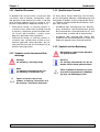
1.2.3 Symbols used in the text and their
meanings
Hinweise,
d.h. wichtige Informationen für den Anwender sind mit einem gekennzeichnet.
Warnings
are marked by a warning triangle
Notes,
i.e. important information for the user,
are marked by an information sign
(5)
(Fig. 5)
(5)
(Fig. 5)
Ziffern in Klammern beziehen sich erläuternd auf Positionsnummern in Abbildungen, bzw. auf Abbildungen selbst.
Figures in brackets refer to item
numbers in drawings / illustrations or to
the drawings / illustrations themselves.
Service Manual / Leica CM3050 S
Version 1.0 12/00 © Leica Microsystems
Page 9
Chapter 1
Introduction
1.2.4 Liability
1.2.4 Haftung
This document is strictly for the use of qualified
service engineers with the requisite technical skills.
Dieses Dokument richtet sich ausschließlich an
qualifizierte Servicetechniker und Servicetechnikerinnen, welche über die notwendigen Fachkenntnisse verfügen.
Only persons who have successfully completed the
appropriate service training provided by Leica Microsystems GmbH, Nussloch and are in the employ
of a company in the Leica Group or of an agency,
distributor, or service workshop duly authorized by
Leica Microsystems GmbH, Nussloch have the
status of qualified service engineer.
Leica Microsystems GmbH, Nussloch accepts no
liability whatever for direct or indirect damage that
may occur due to the unauthorized or improper use
or interpretation of this document by any person
who is not a qualified service engineer in accordance with the above definition.
Qualifizierte Servicetechniker und Servicetechnikerinnen sind solche, die den entsprechenden Servicekurs bei Leica Microsystems GmbH, Nussloch
erfolgreich besucht und der Leica Gruppe oder bei
von Leica Microsystems GmbH, Nussloch autorisierten Vertretung oder Servicewerkstätten tätig
sind.
Wird dieses Dokument von nicht qualifizierten Servicetechnikern und Servicetechnikerinnen verwendet, so lehnt Leica Microsystems GmbH, Nussloch
jegliche Haftung ab für direkte und indirekte Schäden, die durch nicht fachgemäße Anwendung und/
oder Interpretation dieses Dokumentes entstehen.
Service technicians have the following obligations:
•
•
•
To understand and follow the safety information
and instructions on the product and in the
user manual.
To be familiar with local regulations relating to
industrial and non-industrial accident p r e v e n tion in the knowledge that these regulations are
up to date.
Für die Servicetechniker und Servicetechnikerinnen
gelten folgende Pflichten:
•
Sie verstehen und befolgen die Sicherheitsinformationen und die Instruktionen auf dem Produkt
sowie in der Betriebsanleitung.
•
Sie kennen die ortsüblichen gesetzlichen, betrieblichen und außerbetrieblichen Unfallverhütungsvorschriften im Wissen, daß sich diese auf
dem aktuellesten Stand befinden.
•
Sie benachrichtigen Leica schriftlich, sobald an
der Ausrüstung Sicherheitsmängel auftreten.
To inform Leica immediately in writing if the
equipment becomes unsafe.
Service Manual / Leica CM3050 S
Version 1.0 12/00 © Leica Microsystems
Page 10
Chapter 1
Introduction
1.2.5 Instructions
1.2.5 Gefahrenhinweise
To ensure trouble-free operation of the instrument
at all times, the following instructions and warnings
should be observed:
Um eine einwandfreie Funktion des Gerätes zu gewährleisten, sind folgende Hinweise und Warnvermerke zu beachten :
•
The protective devices on the instrument and its
accessories must not be removed or modified.
•
Die Schutzeinrichtungen an Gerät und Zubehör
dürfen weder entfernt noch verändert werden.
•
Only service engineers authorized by Leica may
access, service and repair the internal components of the instrument.
•
Das Gerät darf nur durch von Leica autorisierte
Service-Techniker geöffnet und repariert bzw.
gewartet werden.
1.2.6 Instrument type
1.2.6 Geräte - Typ
All information in this service manual applies only to
the instrument type indicated on the title page.
A nameplate with the serial number is fixed on the
back of the instrument.
Alle Angaben in diesem Service-Manual gelten nur
für den Geräte-Typ, der auf dem Titelblatt angegeben ist. Ein Typenschild mit der Serien-Nr. ist an der
Rückseite des Gerätes befestigt.
1.2.7 Transport und Aufstellung
1.2.7 Transport and installation
• Do not operate the instrument in rooms where risk of
explosion exists!
• Do not expose the instrument to direct sunlight (windows)!
• Do not install the instrument above a heater!
• Install the instrument on an even laboratory bench
which must be absolutely level!
• Two people are needed to lift / carry the instrument!
• Before connecting the instrument to mains, make
sure the correct voltage setting, matching the nominal voltage at the site of installation, has been selected!
• Upon installing the drain hose make sure there is a
gradient from the drain outlet to the waste pipe.
• To protect the user from hazardous solvent fumes,
make sure to operate the instrument either with the
activated carbon filter or the exhaust air hose!
Service Manual / Leica CM3050 S
• Das Gerät darf nicht betrieben werden in Räumen, in
denen Explosionsgefahr besteht!
• Keine direkte Sonneneinstrahlung auf das Gerät
(Fenster)!
• Gerät nicht über einem Heizkörper aufstellen!
• Das Gerät waagerecht auf dem Labortisch aufstellen!
• Zum Hochheben bzw. Tragen des Gerätes sind 2
Personen erforderlich!
• Vor Inbetriebnahme des Gerätes den Spannungswähler entsprechend der Spannung am Aufstellungsort einstellen!
• Den Abflußschlauch mit Gefälle installieren!
• Zum Schutz des Anwenders vor Lösemitteldämpfen
das Gerät auf jeden Fall entweder mit Aktivkohlefilter
oder mit Abluftschlauch betreiben!
Version 1.0 12/00 © Leica Microsystems
Page 11
Chapter 1
1.3
Introduction
Gerätespezifische Informationen
1.3.1 Information on instrument design
and safe handling
This instrument has been built and tested in accordance with the following safety regulations on
electrical measuring, control, regulating and
laboratory devices:
• DIN EN 292
1.3
Gerätespeziefische Informationen
1.3.1 Allgemeine Sicherheitshinweise
Dieses Gerät ist gemäß den Sicherheitsbestimmungen für elektrische Meß-, Steuer-, Regel- und
Laborgeräte
• DIN EN 292,
• DIN EN 61010-1,
• EN 50082-1,
• DIN EN 61010-1
• EN 55011
• EN 50082-1
• IEC 1000-4
• EN 55011
• IEC 1000-4
sowie gemäß der Qualitätsnorm
as well as according to the international quality
standard
• DIN ISO 9001
gebaut und geprüft.
• DIN ISO 9001
In order to maintain this condition and to ensure
safe operation, the operator must observe the instructions and warnings contained in this instruction manual.
Um diesen Zustand zu erhalten und einen gefahrlosen Betrieb sicherzustellen, muß der Anwender
die Hinweise und Warnvermerke beachten, die in
dieser Gebrauchsanweisung enthalten sind.
1.3.2 Eingebaute Sicherheitssysteme
1.3.2 Integrated safety devices
The instrument is equipped with the following safety
devices:
Das Gerät ist mit den folgenden Sicherheitseinrichtungen ausgestattet :
• Handradverriegelung
• Handwheel lock
• Zentrieren des Handradgriffs
• Handwheel grip centering
• Not-Aus-Funktion
(nur bei Geräten mit Schneidemotor)
• Emergency stop function
• Fingerschutz am Messerhalter
(instruments with sectioning motor only)
• Knife holder equipped with knife guard
The safety devices installed by the manufactu-rer of
the instrument only constitute the basis of accident
prevention.
Mainly responsible for accident-free operation is
above all the institution which owns the instrument
and, in addition, the designated personnel who
operate, service or repair the instrument.
Service Manual / Leica CM3050 S
Die Sicherheitseinrichtungen, die vom Hersteller an
dem Gerät angebracht wurden, sind nur die Grundlage des Unfallschutzes.
Die Hauptverantwortung für einen unfallfreien
Arbeitsablauf tragen vor allem der Unternehmer,
der das Gerät betreibt und zusätzlich die von ihm
benannten Personen, die das Gerät bedienen,
warten oder reparieren.
Version 1.0 12/00 © Leica Microsystems
Page 12
Chapter 1
Introduction
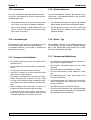
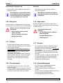
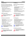
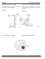
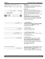
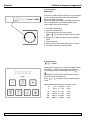
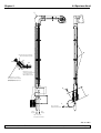
1.3.3 Handradverriegelung
1.3.3 Locking the handwheel
Always cover the cutting edge with the
knife guard and lock the handwheel:
Vor jeder Manipulation an Messer und
Objekt, vor jedem Objektwechsel und
während der Arbeitspausen:
• Prior to doing any work on knife
and / or specimen.
• Handrad verriegeln!
• Prior to exchanging specimens.
• Schneide mit Fingerschutz
abdecken!
• During work breaks.
The handwheel can be locked in 2 positions:
- with the grip in the uppermost position (left),
- with the grip in the lowest position (right).
Das Handrad läßt sich in 2 Positionen verriegeln:
- mit dem Griff nach oben (Abb. links)
- mit dem Griff nach unten (Abb. rechts)
2
2
Verriegeln
Locking
- Rotate handwheel, until grip (1) is in upper or
lower position.
- To lock, press pin (2) to the right into position
(2b). The upper locking position for pin (2) is
marked by a black dot (4).
Instruments with sectioning motor
- Handrad drehen, bis Griff (1) oben bzw. unten
steht.
- Zum Verriegeln Blockierstift (2) nach rechts in
Position (2b) drücken.
Die Verriegelungsposition für den Blockierstift (2)
ist oben durch einen schwarzen Punkt (4)
markiert.
Geräte mit Schneidemotor
The sectioning motor is now blocked.
Der Schneidemotor ist nun blockiert.
All instruments
Alle Gerätevarianten
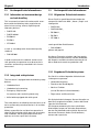
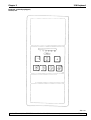
The message ‘LOCKED’ in the display of control
panel 1 indicates that the handwheel has been
locked:
C T - 3 0 ° C
O T - 3 5 ° C
L O C K E D
Die Handradverriegelung wird im Display des
Bedienfeldes 1 durch das Wort ‘SPERRE’ angezeigt:
C T - 3 0 ° C
O T - 3 5 ° C
L O C K E D
Unlocking
Entriegeln
- To unlock, push locking pin (2) to the left into
position (2a).
- Display indication ‘LOCKED’ disappears.
- Zum Entriegeln den Blockerstift (2) nach links in
Position (2a) drücken.
- Die Anzeige ‘SPERRE’ im Display erlischt.
Service Manual / Leica CM3050 S
Version 1.0 12/00 © Leica Microsystems
Page 13
Chapter 1
Introduction
Instruments with sectioning motor
Geräte mit Schneidemotor
The sectioning motor can now be activated again.
Der Schneidemotor kann nun wieder in Gang
gesetzt werden.
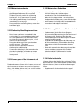
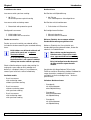
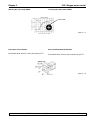
1.3.4 Centering the handwheel grip
1.3.4 Zentrieren des Handradgriffs
During motorized sectioning, for safety
reasons always center the handwheel
grip!
- To center grip (1), pull outwards and pivot into
center of handwheel.
- When released, the grip locks into position.
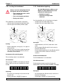
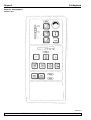
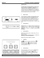
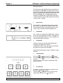
1.3.5 Emergency stop function
The emergency stop is activated via the red
emergency stop button in control panel 2 or via the
footswitch
Beim Arbeiten im motorischen
Schneidebetrieb:
• Handradgriff aus Sicherheitsgründen
zentrieren!
- Zum Zentrieren Griff (1) leicht nach außen ziehen
und ins Zentrum des Handrads schwenken.
- Beim Loslassen rastet der Griff ein.
1.3.5 Not-Aus-Funktion
Die Not-Aus-Funktion wird mit dem roten Not-AusSchalter am Bedienfeld 2 oder dem Fußschalter
aktiviert.
Control panel 2
Bedienfeld 2
Footswitch
Activating the emergency stop function
- Press emergency stop button or step on
footswitch forcefully.
STOP (red) lights up.
As soon as the emergency stop function is
activated, the sectioning motor stops.
Service Manual / Leica CM3050 S
Fußschalter
Aktivieren
- Not-Aus-Schalter drücken bzw. Fußschalter fest
durchdrücken.
STOP (rot) leuchtet.
Der Schneidemotor stoppt unmittelbar nach
Aktivierung der Not-Aus-Funktion.
Version 1.0 12/00 © Leica Microsystems
Page 14
Chapter 1
Introduction
Deactivating the emergency stop
Entriegeln
- To deactivate, rotate emergency stop button in
direction of arrow.
- Zum Deaktivieren den Not-Aus-Schalter in
Pfeilrichtung drehen.
If the emergency stop function has been
activated by the footswitch, unlocking is
not necessary (func-tion is unlocked as
soon as the footswitch is released).
Nach Aktivieren der Not-Aus-Funktion
über den Fußschalter ist kein Entriegeln
erforderlich.
1.3.6 Knife guard
1.3.6 Fingerschutz
All knife holders are equipped with a knife guard
(see separate instruction manuals on knife holders).
Alle Messerhalter sind mit einem Fingerschutz
versehen (siehe separate Gebrauchsanweisungen
für Messerhalter).
Always cover the cutting edge with the
knife guard:
• Prior to doing any work on knife
and/ or specimen.
Schneide mit Fingerschutz
abdecken:
• vor jeder Manipulation an Messerhalter oder Objekt
• Prior to exchanging specimens.
• vor jedem Objektwechsel
• During work breaks.
• in Arbeitspausen
1.3.7 Transport
1.3.7 Transport
- To avoid severe damage to the instrument by
running it while the compressor oil is displaced
from its regular position:
- Do not tilt the instrument, only transport in an
upright position.
- After transport, wait at least 4 hours before
turning the instrument on.
The compressor oil may have been displaced
during transport and must settle to its original
positin before switchingthe instrument on.
Otherwise, the instrument may be severely
damaged.
- Zur Vermeidung schwerer Schäden am Gerät
durch Betrieb bei verlagertem Verdichteröl:
- Gerät beim Transport nicht kippen, nur stehend
transportieren.
- Nach einem Transport eine Mindestwartezeit
von 4 Stunden vor Inbetriebnahme des Gerätes
einhalten!
Das beim Transport verlagerte Verdichteröl muß
vor Inbetriebnahme in seine Normalposition
zurückfließen. Andernfalls können schwere
Schäden am Gerät entstehen.
1.3.8 Site requirements
1.3.8 Standortbedingungen
- Do not operate the instrument in rooms with
explosion hazard.
- To ensure proper instrument function maintain a
minimum distance of 10 cm between walls and/
or furniture and all sides of the instrument!
- Das Gerät nicht in explosionsgefährdeten
Räumen aufstellen bzw. betreiben!
- Zur Gewährleistung einer einwandfreien
Funktion:
- An allen Seiten einen Mindestabstand von 10 cm
zwischen dem Gerät und Wänden/
Einrichtungsgegenständen einhalten!
Service Manual / Leica CM3050 S
Version 1.0 12/00 © Leica Microsystems
Page 15
Chapter 1
Introduction
1.3.9 Electrical connections
1.3.9 Elektrischer Anschluß
- Do not use extension cords for connecting the
instrument to mains.
Fire hazard!
Instrument malfunctions caused by voltage drop.
- During the start-up phase of the compressor, the
nominal voltage must not drop below the values
specified in chapter 1.3.31 ‘Technical data’!
The compressor needs a start-up current at
between 25 and 35 A .
- Ensure uniform current supply according to
specifications. Electrical power supply deviating
from specifications damages the instrument.
- Therefore, arrange for the electrical installations on site to be checked by a trained
professional and make sure any necessary
upgrades are installed!
- Have the circuit protected by a fuse of its own!
- Do not connect any other consumers to the
same circuit.
- Prior to connecting the instrument to mains,
make sure the electrical power supply in your
laboratory corresponds to the values
indicated on the instrument nameplate
(located at the rear of the instrument)!
- Keine Verlängerungsleitung zum Anschluß an
das Stromnetz benutzen.
Brandgefahr!
Funktionsstörungen am Gerät durch Spannungsabfall!
- Beim Anlaufen der Kälteanlage die nötige
Mindest-Nennspannung nicht unterschreiten!
Benötigter Verdichter-Anlaufstrom:
25 bis 35 A; (s. Kap. 1.3.31 ‘Technische Daten’)
- Spezifikationsgerechte, gleichbleibende Stromversorgung gewährleisten.Nicht spezifikationsgerechte Stromversorgung führt zu Schäden am
Gerät.
- Daher Elektroinstallation vor Ort durch einen
Fachmann überprüfen und ggfs. überarbeiten
lassen!
- Stromkreis separat absichern!
- Keine weiteren Verbraucher an den Stromkreis anschließen.
- Vor dem Anschließen des Gerätes an das
Stromnetz prüfen, ob die elektrischen
Anschlußwerte Ihres Labors mit den Angaben
auf dem Typenschild des Gerätes
übereinstimmen!
1.3.10 Handling microtome knives/blades.
1.3.10 Umgang mit Messern
Microtome knives and disposable
blades have extremely sharp cutting
edges and can cause serious injuries.
- Handle knives / blades with utmost care.
- Never leave any knives / blades in unprotected
places!
- Never place a knife, no matter where, with the
cutting edge facing upwards.
- Never try to catch a falling knife.
- Always insert the specimen before inserting the
knife.
Mikrotommesser/Einwegklingen haben
extrem scharfe Schneiden und können
schwere Verletzungen verursachen.
- Messer vorsichtig handhaben!
- Messer bzw. ausgebaute Messerhalter mit
eingesetztem Messer nicht offen liegen
lassen!
- Messer nie mit der Schneide nach oben abstellen!
- Niemals versuchen, fallende Messer aufzufangen!
- Stets zuerst das Objekt und danach das
Messer einspannen!
1.3.11 Knife guard/handwheel lock
1.3.11 Fingerschutz/Handradverriegelung
Always cover the cutting edge with the knife
guard andlock the handwheel:
- Prior to doing any work on knife and / or
specimen.
- Prior to exchanging specimens.
- During work breaks.
Service Manual / Leica CM3050 S
Den Fingerschutz über die Schneide legen sowie
das Handrad verriegeln:
- Vor jeder Manipulation an Messer und/oder
Objekt
- Vor jedem Objektwechsel
- Während der Arbeitspausen
Version 1.0 12/00 © Leica Microsystems
Page 16
Chapter 1
Introduction
1.3.12 Motorized sectioning
1.3.12 Motorisches Schneiden
- Do not interrupt sectioning / trimming by setting
the sliding potentiometer to zero speed!
This does not really switch the sectioning
function off - it only operates at ‘0’ speed.
If the sliding potentiometer is accidentally
moved, the instrument will resume sectioning
immediately (risk of injury)!
- During motorized sectioning, always center the
handwheel grip!
- Schneiden/Trimmen im Dauerhub nicht durch
Auf-Null-Stellen des Schiebereglers
unterbrechen! Der Schneidebetrieb wird
dadurch nicht abgeschaltet - versehentliches
Antippen des Schiebereglers setzt die Schneidebewegung wieder in Gang (Verletzungsgefahr!)
- Beim Arbeiten im motorischen Schneidebetrieb
immer den Handradgriff zentrieren!
1.3.13 Abtauung / Gefrorenes Probematerial
1.3.13 Defrosting/Handling frozen tissue
- Never leave specimens unattended in the
cryochamber over an extended period of time!
In case of power failure or instrument failure,
or during the automatic defrost cycle, tissue
material can be destroyed.
- During the defrost cycle the cryochamber is
partially warmed. - Therefore:
- Remove sensitive specimens from the
chamber prior to defrosting.
- If automatic defrosting is programmed to take
place during the night, remember to remove
all specimens from the cryo-chamber prior to
leaving work.
- Probenmaterial nicht über einen längeren
Zeitraum ohne Überwachung im Gerät belassen!
Bei Stromausfall, Defekt des Gerätes oder
während der zyklischen Abtauung kann Probenmaterial zerstört werden!
- Empfindliches Probengut vor der Abtauung aus
der Kammer nehmen. Während der Abtauung
findet eine partielle Erwärmung der Kammer
statt.
- Wenn die automatische Abtauung während der
Nacht stattfindet, vergessen Sie nicht, bei
Arbeitsende alles Probenmaterial aus der
Kammer zu nehmen!
1.3.14 Kalte Geräteteile
1.3.14 Frozen parts of the instrument and
frozen accessories
Prolonged contact of bare skin to frozen surfaces of
the instrument or to frozen accessories (specimen
discs, knife holder, shelves etc.) can cause frostbite.
- Wear protective gloves.
Service Manual / Leica CM3050 S
Längerer Kontakt der bloßen Haut mit kalten Teilen
des Gerätes bzw. mit kaltem Zubehör (Probenhalter,
Messerhalter etc.) kann zu Gefrierverbrennungen
führen.
- Gegebenenfalls Schutzhandschuhe tragen!
Version 1.0 12/00 © Leica Microsystems
Page 17
Chapter 1
Introduction
1.3.15 Infektiöses/radioaktives Material
1.3.15 Infectious/radioactive material
Use caution when working with
potentially infectious specimens - Risk
of infection!
When working with potentially infectious /
radioactive specimens:
- Wear protective clothes (gloves, protective
boots, mask, lab coat), in compliance with
radiation safety regulations and/or in-house
regulations on handling infectious /
radioactive material.
When working with radioactive specimens:
- Comply with applicable radiation safety
regulations!
- Dispose of radioactive specimen waste
according to applicable regulations.
Beim Arbeiten mit möglicherweise
infektiösem Probenmaterial Infektionsgefahr!
Beim Arbeiten mit infektiösem und/oder radioaktiv
kontaminiertem Probenmaterial:
- Schutzkleidung tragen (Handschuhe, Überschuhe, Gesichtsmaske, Schutzkleidung), gemäß
der Strahlenschutzverordnung bzw. den im
jeweiligen Labor gültigen Richtlinien für den
Umgang mit radioaktiv kontaminiertem/
infektiösem Material!
Beim Arbeiten mit radioaktiv kontaminiertem
Material:
- Strahlenschutzvorschriften beachten!
- Radioaktive Probenabfälle nach den jeweils
geltenden Vorschriften entsorgen!
1.3.16 Disinfection and cleaning
1.3.16 Desinfektion und Reinigung
- Prior to disinfection, switch the instrument off
and unplug it from mains.
- For removal of the microtome from the
cryochamber, see chapter 1.3.17 Removing
microtome.
- For disinfection, wear protective gear:
(gloves, mask, lab coat etc.)!
- For disinfection, only use alcohol-based
disinfectants!
- Do not use solvents (xylene, acetone etc.) for
cleaning or disinfection!
- Do not spray disinfectants into the evaporator!
Risk of icing!
- Explosion hazard when working with alcohol:
Make sure the premises are appropriately
ventilated!
- When using disinfectants and detergents,
comply with all safety instructions supplied by
the manufacturer of the product!
- Dispose of waste liquids from disinfection/
cleaning as well as of sectioning waste
according to applicable regulations on disposal
of special category waste!
- Disinfected accessories must be thoroughly dry
when reinserting them into the chamber!
Risk of icing!
- Make sure the chamber is completely dry before
switching the instrument back on:
Explosion hazard through alcohol vapors!
Risk of icing!
Service Manual / Leica CM3050 S
- Vor der Desinfektion Gerät ausschalten und
Netzstecker ziehen.
- Falls das Mikrotom ausgebaut wird: siehe
Kapitel 1.3.7 ‘Ausbau des Mikrotoms’.
- Bei Desinfektionsarbeiten
Personenschutzmaßnahmen beachten:
(Handschuhe, Mundschutz, Laborkittel etc.
tragen)!
- Zur Desinfektion nur Mittel auf alkoholischer
Basis verwenden!
- Keinesfalls mit Lösungsmitteln (Xylol, Aceton
etc.) Reinigungs- oder Desinfektionsarbeiten
durchführen!
- Desinfektionsmittel nicht in den Verdampfer
sprühen!
Vereisungsgefahr!
- Explosionsgefahr beim Umgang mit Alkohol: Für
ausreichende Belüftung sorgen!
- Beim Umgang mit Reinigungs- und Desinfektionsmitteln die Herstellervorschriften des
jeweiligen Mittels beachten!
- Desinfektions- bzw. Reinigungsflüssigkeiten
sowie Schnittabfälle nach den jeweils geltenden
Sondermüllvorschriften entsorgen!
- Desinfizierte Zubehörteile vor dem Wiedereinbau
gründlich trocknen. - Eisbildung!
- Gerät erst nach vollständiger Trocknung der
Kammer wieder einschalten:
Explosionsgefahr durch Alkoholdämpfe!
Vereisungsgefahr!
Version 1.0 12/00 © Leica Microsystems
Page 18
Chapter 1
Introduction
1.3.17 Removing/reinstalling the microtome
1.3.17 Ausbau/Einbau des Mikrotoms
Before removing the microtome
Vor Ausbau des Mikrotoms
- Switch instrument off.
- Unplug from mains.
- Place handwheel grip in lowest position and
lock.
When removing the microtome, the specimen
head must always be lok-ked in the lowest
position.
Otherwise the upper part of the slot cover
might be bent and consequently damaged!
- Gerät ausschalten.
- Netzstecker ziehen.
- Handradgriff in tiefste Position stellen und
Handrad verriegeln.
Beim Herausnehmen des Mikrotoms muß der
Objektkopf in der tiefsten Position stehen, damit
die Schlitzabdeckung des Mikrotoms oben nicht
abgeknickt wird!
Beim Herausnehmen des Mikrotoms
When removing the microtome
- Wear gloves when removing the microtome
while it is still frozen. Risk of frost bite!
- On instruments with specimen cooling: do not
distort the refrigerating tube!
If distorted it might break, causing extremely
cold refrigerant to escape. Risk of frost bite!
- Bei kaltem Mikrotom geeignete Schutzhandschuhe tragen Gefrierverbrennungen bei
längerem Kontakt mit kalten Teilen!
- Bei Geräten mit Objektkühlung beim Herausnehmen den Kühlschlauch nicht verdrehen!
Durch Verdrehen kann ein Leck entstehen, aus
dem extrem kaltes Kältemittel ausströmt.
Gefahr von Gefrierverbrennungen!
Before reinstalling the microtome
Vor dem Wiedereinbau
- Microtome must be completely dry.
Humidity in the interior of the microtome
freezes and causes microtome
malfunctions and/or damage to the
microtome.
- All accessories/tools removed from the
cryochamber must be thoroughly dry before
putting them back into the chamber!
Risk of icing!
- Mikrotom muß vollständig trocken sein.
Feuchtigkeit im Mikrotominneren gefriert und
führt zu Schäden am Mikrotom bzw. zu
Funktionsstörungen.
- Alle aus dem kalten Kryostaten entnommenen
Teile vor dem Zurücklegen in die Gefrierkammer
gründlich trocknen!
Bereifung!
1.3.18 Display message ‘Dry microtome’
1.3.18 Fehlermeldung ‘Trockne Mikrotom’
If the error message ‘Dry Microtome’ is displayed in
control panel 1, the following has happened:
Erscheint beim Einschalten des Geräts im Display in
Bedienfeld 1 die Meldung ‘Trockne Mikrotom’, dann
hat das folgende Ursache:
- Cryochamber refrigeration has been
interrupted for an extended period of time
(e.g. power failure), causing the chamber
temperature to rise into the positive digits.
- If this message appears, do not switch on the
instrument but remove the microtome from
the chamber, disinfect, if necessary, and dry
thoroughly before reinstalling it into the
chamber .
Service Manual / Leica CM3050 S
- längere Unterbrechung der Kammerkühlung
wobei die Kammertemperatur in den Plusbereich
gestiegen ist.
- In diesem Fall Gerät nicht einschalten sondern
Mikrotom ausbauen, gegebenenfalls
desinfizieren, gründlich trocknen und erst dann
wieder einbauen.
Version 1.0 12/00 © Leica Microsystems
Page 19
Chapter 1
Introduction
1.3.19 Maintenance
1.3.19 Wartung
Only technical service engineers authorized by
Leica may access the internal components of the
instrument for service and repair. The fluorescent
light lamp (chamber illumination), unless broken or
splintered, can be replaced by the user:
Das Gerät darf für Wartungs- und Reparaturarbeiten nur von autorisierten Servicetechnikern
geöffnet werden.
- Switch off mains switch!
- Unplug the instrument from mains!
- If the lamp is broken or splintered: Have
lamp replaced by Leica Technical Service!
Risk of injury!
- Use only those replacement lamps that
correspond to technical specification (see
chapter 1.3.31 ‘Technical Data’).
- Die Lampe kann im Normalfall vom Benutzer
ausgetauscht werden.
- Gerät mit dem Netzschalter ausschalten!
- Netzstecker ziehen!
- Bei abgebrochener/zerbrochener Lampe: Lampe
vom Kundendienst tauschen lassen!
Verletzungsgefahr!
- Ersatzleuchtstofflampen müssen der vorgegebenen technischen Spezifikation entsprechen!
(siehe. Kap. 1.3.31 ‘Technische Daten).
1.3.20 Site requirements
1.3.20 Standortbedingungen
Make sure to read and follow all safety
instructions in chapter 1.1.8 ‘Site
requirements’!
Sicherheitshinweise unter Kapitel 1.1.8
‘Standortbedingungen’ unbedingt lesen
und beachten!
1.3.21 General site requirements
1.3.21 Allgemeines
- No direct sunlight.
- Electrical power supply within distance (length
of power cord = approx. 4 meters - do not use
extension cords!).
- No draft (caused by air conditioning etc.).
- Even floor surface.
- Practically vibration-free floor.
- Handwheel easily accessible.
- Room temperature constantly below +22 °C.
- Relative humidity of air maximum 60 %.
- Keine direkte Sonneneinstrahlung
- Spannungsversorgung in angemessener Nähe.
Länge des Netzanschlußkabels ca. 4 m.
- Keine Zugluft (Klimaanlage etc.)
- Glatter, ebener Bodenbelag
- Weitgehend schwingungsfreier Boden
- Handrad frei und bequem zugänglich
- Raumtemperatur durchgängig unter 22 °C
- Relative Luftfeuchtigkeit maximal 60 %
High ambient temperature and/or high
air humidity negatively affect instrument
cooling performance!
Hohe Raumtemperaturen bzw. zu hohe
Luftfeuchtigkeit beeinträchtigen die
Kühlleistung!
1.3.22 Elektrische Anschlüsse
1.3.22 Electrical connections
Make sure to read and follow all safety
instructions in chapter 1.3.9 ‘Electrical
connections’!
Service Manual / Leica CM3050 S
Sicherheitshinweise unter Kapitel 1.3.9
‘Elektrischer Anschluß’ unbedingt lesen
und beachten!
Version 1.0 12/00 © Leica Microsystems
Page 20
Chapter 1
Introduction
1.3.23 Unpacking and installation
1.3.23 Auspacken und Aufstellen
Unpacking instructions are always located in a
transparent protective envelope on the outside of
the instrument shipping crate.
Die Auspackanleitung befindet sich außen an der
Transportbox, in der das Gerät geliefert wurde.
Make sure to read and follow all safety
instructions provided in chapter 1.3.7
‘Transport’ and on the unpacking
instructions!
Sicherheitshinweise unter Kapitel 1.3.7
‘Transport’ bzw. auf der
Auspackanleitung unbedingt lesen und
beachten!
1.3.24 Wiederverpacken
1.3.24 Repacking
We recommend to keep the original shipping crate
and the unpacking instructions for the Leica
CM3050 S. For repacking, proceed as per unpacking
instructions, in reverse order.
Wir empfehlen, die Auspackanleitung sowie evtl.
die Original-Transportverpackung des Leica CM3050
S aufzubewahren. Zum Wiederverpacken die auf
der Auspackanleitung angegebenen Schritte in
umgekehrter Reihenfolge durchführen.
1.3.25 Standard delivery
1.3.25 Standardlieferumfang
Together with the Leica CM3050 S instrument you
receive a box containing the following standard
accessories:
Mit dem Kryostaten CM3050 S erhalten Sie einen
Karton mit folgendem Standardzubehör:
1 Handwheel (including screw, spring washer
and cover disc)
1 Heat extractor, stationary
1 Low-temperature stabilizer for heat extractor
3 Specimen discs, 30 mm ø
1 Storage shelf, right
1 Storage shelf, left
1 Section waste tray
1 Rubber mat
1 Cover for quick-freeze shelf
2 Brushes (brush, fine and ‘Leica’ brush)
1 Shelf for brushes
1 Tool set
- 1 Allen key, size 4
- 1 Allen key, size 5
- 1 Allen key, size 6
- Single-ended open-jaw wrench
1 Bottle of embedding medium for
cryosectioning, 125 ml
1 Bottle of cryostat oil No. 407, 100 ml
1 Instruction manual
(German, English, French, Spanish)
Service Manual / Leica CM3050 S
1 Handrad (inkl. Schraube, Federscheibeund
Abdeckscheibe)
1 Wärmeableitblock, stationär
1 Tieftemperaturstabilisator für Wärmeableitblock
3 Objektplatten, 30 mm ø
1 Ablageblech rechts
1 Ablageblech links
1 Schnittabfallwanne
1 Gummimatte
1 Abdeckung für Schnellgefrierleiste
2 Pinsel (Pinsel, dünn; ‘Leica’-Pinsel)
1 Pinselablage
1 Werkzeugsatz
- 1 Innensechskantschlüssel, SW 4
- 1 Innensechskantschlüssel, SW 5
- 1 Innensechskantschlüssel, SW 6
- 1 Einmaulschlüssel, SW 16
1 Flasche Gefriereinbettmedium, 125 ml
1 Flasche Kryostatöl Nr. 407, 100 ml
1 Gebrauchsanweisung (Deutsch, Englisch,
Französisch, Spanisch)
Version 1.0 12/00 © Leica Microsystems
Page 21
Chapter 1
Introduction
In addition to the above
Darüber hinaus
Instruments with specimen cooling:
Bei Geräten mit Objektkühlung:
1 90° Prism
for low temperature quick freezing
1 90°-Prisma
zum Tieftemperatur-Schnellgefrieren
Instruments with sectioning motor:
Bei Geräten mit Schneidemotor:
1 Footswitch with protective guard
1 Fußschalter mit Trittschutz
Configured instruments:
Bei konfigurierten Geräten:
1 Knife holder base
1 Knife holder with accessories
1 Messerhalterbasis
1 Messerhalter mit Zubehör
Further accessories
Weiteres Zubehör, das zusammen mit dem
Standardlieferumfang ausgeliefert wird
Further accessories which you ordered will be
included in the box containing the standard delivery
items.
Knife holders are delivered with anti-roll
guide, knife guard, and a separate
instruction manual.
In case of non-configured instruments,
the knife holder is not a part of standard
delivery but must be ordered separately.
Check all delivered parts against the packing list
and against your order to verify whether the
delivery is complete! If there is any difference,
contact your local Leica office immediately.
Available models
- Basic instrument
with sectioning motor
without specimen cooling
- Basic instrument
without sectioning motor
with specimen cooling
- Basic instrument
with sectioning motor
with specimen cooling
Weiteres Zubehör, das Sie zusätzlich zum
Standardlieferumfang bestellt haben, finden Sie
ebenfalls im Zubehörkarton.
Messerhalter werden komplett mit
Schnittstrecker, Fingerschutz sowie
einer separaten Gebrauchsanweisung
ausgeliefert.
Bei nicht konfigurierten Geräten muß
der Messerhalter separat bestellt
werden.
Vergleichen Sie die gelieferten Teile mit der
Teileliste und Ihrer Bestellung. Sollten Sie Abweichungen feststellen, wenden Sie sich bitte unverzüglich an Ihre zuständige Leica - Verkaufsgesellschaft!
Lieferbare Gerätevarianten
- Grundgerät
mit Schneidemotor
ohne Objektkühlung
- Grundgerät
ohne Schneidemotor
mit Objektkühlung
- Grundgerät
mit Schneidemotor
mit Objektkühlung
Service Manual / Leica CM3050 S
Version 1.0 12/00 © Leica Microsystems
Page 22
Chapter 1
Introduction
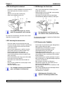
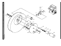
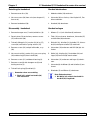
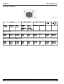
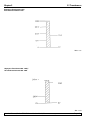
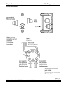
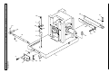
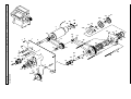
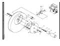
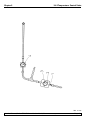
1.3.26 Installing the handwheel
1.3.26 Montage des Handrades
- Insert pin (1) of the handwheel shaft into hole (2).
- Place spring washer (3) onto screw (4) as
shown.
- Tighten screw (4) with an Allen key.
- Cover with selfadhesive disc (5).
- Stift (1) der Handradachse in Bohrung (2) des
Handrads einsetzen.
- Federscheibe (3) wie in der Abb. unten gezeigt
auf Schraube (4) aufsetzen.
- Schraube (4) mit Inbusschlüssel festziehen.
- Selbstklebende Abdeckscheibe (5) anbringen.
For purposes of transport (e.g. narrow
doors), the handwheel can be removed.
To remove the handwheel, proceed as described
above but in reverse order.
Das Handrad kann zum Transport, z.B.
bei schmalen Türen, demontiert werden.
Die Demontage erfolgt in umgekehrter Reihenfolge
wie oben beschrieben.
1.3.27 Inserting the accessories
1.3.27 Einsetzen des Zubehörs
- Place the rubber mat on top of the housing.
- Insert the storage shelves into the cryochamber.
-Install the stationary heat extractor into the
quick-freeze shelf .
- Insert the low temperature stabilizer into the
quick freeze shelf (it must be located in the
pivoting range of the heat extractor.
- Insert section waste tray and brush shelf.
- Install knife holder base onto microtome base
plate and clamp.
- Install knife holder and clamp (see knife holder
instruction manual for details).
- Place knife case with knife into chamber to
precool.
- Place all tools needed for section prepara-tion
into the chamber.
- Close the sliding window.
For a complete overview of all individual
parts, see Chapter 1.3.30 ‘Overview’.
- Gummimatte in die Vertiefung der Ablagefläche
oben auf dem Gehäuse legen.
- Ablagebleche in die Kammer einsetzen.
- Stationären Wärmeableitblock in die
Schnellgefrierleiste einschrauben.
- Tieftemperaturstabilisator in die
Schnellgefrierleiste einsetzen, so daß er sich im
Schwenkbereich des stationären Wärmeableitblocks befindet.
- Schnittabfallwanne und Pinselablage einsetzen.
- Messerhalterbasis auf die Mikrotomgrundplatte
aufsetzen und klemmen.
- Messerhalter aufsetzen und klemmen
(Einzelheiten finden Sie in der Gebrauchsanweisung zum Messerhalter).
- Messerkasten mit Messer zum Vorkühlen in die
Kammer stellen.
- Alle für die Objektpräparation benötigten Werkzeuge in die Kammer legen.
- Schiebefenster schließen.
Abbildungen der Einzelteile, siehe
Kapitel 1.3.30 Gerätegesamtübersicht.
Service Manual / Leica CM3050 S
Version 1.0 12/00 © Leica Microsystems
Page 23
Chapter 1
Introduction
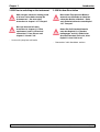
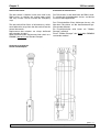
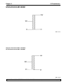
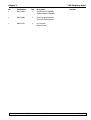
1.1.28 The footswitch
1.3.28 Der Fußschalter
Function
Funktion
The footswitch performs the same task as the RUN/
STOP and RUN/ENABLE keys (activating/
deactivating motorized sectioning / trimming). In
addition, the footswitch can be used to activate the
emergency stop function.
Der Fußschalter führt die Funktionen der RUN/STOP
und RUN/ENABLE-Tasten aus (Motorisches
Schneiden bzw. Trimmen ein- und ausschalten).
Zusätzlich kann über den Fußschalter auch die NotAus-Funktion ausgelöst werden.
Models with footswitch
Gerätvarianten mit Fußschalter
All instruments with sectioning motor.
Alle Geräte mit Schneidemotor.
In all instrument models that are
delivered with footswitch, the footswitch must be installed! - Otherwise the
instruments are not functional.
Bei den Gerätevarianten, die mit Fußschalter ausgeliefert werden, muß der
Fußschalter angeschlossen werden andernfalls ist das Gerät nicht betriebsbereit!
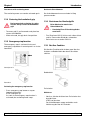
Connecting the footswitch
Fußschalter anschließen
- Insert footswitch into port (1) and secure.
- Fußschalter in Anschlußbuchse (1) stecken und
fixieren.
Service Manual / Leica CM3050 S
Version 1.0 12/00 © Leica Microsystems
Page 24
Chapter 1
Introduction
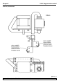
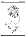
1.3.29 Prior to switching on the instrument
After transport, observe a waiting period
of at least 4 hours before turning the
instrument on! - See also safety
instructions in chapter 1.3.7 ‘Transport’.
Have you observed all safety
instructions in chapters 1.3.8 ‘Site
requirements’ and 1.3.9 ‘Electrical
connections’? If not, Please read
chapters 1.3.8 and 1.3.9!
1.3.29 Vor dem Einschalten
Nach einem Transport eine Mindestwartezeit von 4 Stunden vor Inbetriebnahme des Gerätes einhalten! - Siehe
auch Sicherheitshinweise unter Kapitel
1.3.7 ‘Transport’.
Haben Sie die Sicherheitshinweise
unter den Kapiteln 1.3.8 ‘Standortbedingungen’ und 1.3.9 ‘Elektrischer
Anschluß’ beachtet? Falls nein, bitte
Kapitel 1.3.8 und 1.3.9 lesen!
- Insert mains plug into wall outlet.
- Netzstecker in die Steckdose stecken.
Service Manual / Leica CM3050 S
Version 1.0 12/00 © Leica Microsystems
Page 25
Chapter 1
Introduction
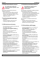
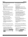
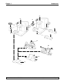
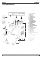
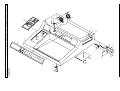
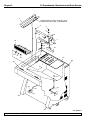
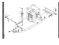
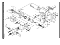
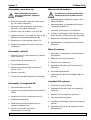
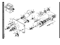
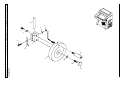
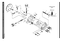
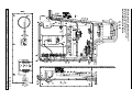
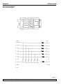
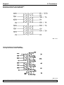
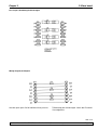
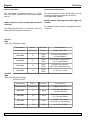
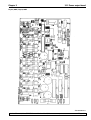
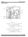
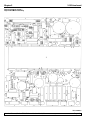
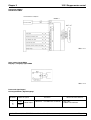
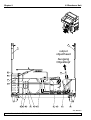
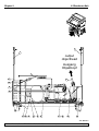
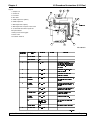
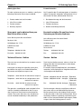
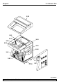
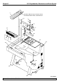
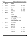
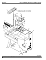
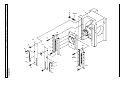
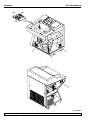
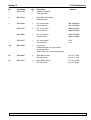
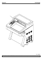
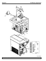
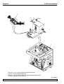
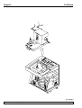
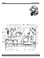
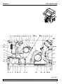
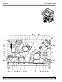
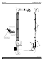
1.3.30 Overview
1
2
3
4
5
6
7
4
3
2
5
6
8
9
10
11
12
13
14
15
9
10
16
17
1
8
18
19
20
21
22
11
7
12
Cryostat CM3050 S
Control panel 1
Control panel 2
Storage shelf, left
Storage shelf, right
Rubber mat
Mains switch /
Automatic cutout for instrument,
Automatic cutout for sectioning
motor,
Footswitch port
Quick-freeze shelf
Stationary
heat extractor
Mobile heat extractor
Specimen disc
Thermoblock (optional)
Section waste tray
Brush shelf
Specimen head w/o specimen
cooling
Specimen head with
specimen cooling (Option)
90° Prism
(instruments withspecimen coo
ling only)
Knife holder base
Knife holder CE
Knife holder CN
Knife holder CS
Footswitch with
protective guard
22
Service Manual / Leica CM3050 S
Version 1.0 12/00 © Leica Microsystems
Page 26
Chapter 1
Introduction
15
16
11
11
13
17
14
21
20
19
18
Service Manual / Leica CM3050 S
Version 1.0 12/00 © Leica Microsystems
Page 27
Chapter 1
Introduction
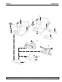
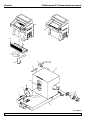
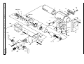
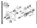
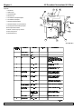
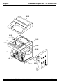
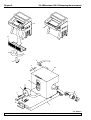
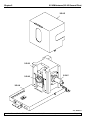
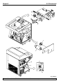
1.3.30 Gerätegesamtübersicht
4
3
2
5
6
1
2
3
4
5
6
7
8
9
10
11
12
13
14
15
9
10
16
17
18
19
20
21
22
1
8
11
7
Kryostat CM3050 S
Bedienfeld 1
Bedienfeld 2
Ablageblech links
Ablageblech rechts
Gummimatte
Netzschalter,
Sicherungsautomat,
Fußschalteranschluß
Schnellgefrierleiste
Stationärer
Wärmeableitblock
Mobiler Wärmeableitblock
Objektplatte
Thermoblock (Option)
Schnittabfallwanne
Pinselablage
Objektkopf ohne
Objektkühlung
Objektkopf mit Objektkühlung
(Option)
90° Prisma (Zubehör zu Geräten
mit Objektkühlung)
Messerhalterbasis
Messerhalter CE
Messerhalter CN
Messerhalter CS
Fußschalter mit
Trittschutz
12
22
Service Manual / Leica CM3050 S
Version 1.0 12/00 © Leica Microsystems
Page 28
Chapter 1
Introduction
15
16
11
11
13
17
14
21
20
19
18
Service Manual / Leica CM3050 S
Version 1.0 12/00 © Leica Microsystems
Page 29
Chapter 1
Introduction
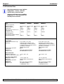
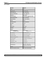
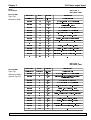
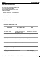
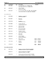
1.3.31 Technical Data
Operating temperature range (ambient
temperature): + 18°C to + 40°C. All
specifications related to temperature are valid only up to an ambient
temperature of + 22°C and relative air
humidity of less than 60%!
Type
Marks of conformity
Nominal voltage
Nominal frequency
Power draw
Max. start-up current for 5 sec
Protective fuse
Automatic cutout
Pollution degree
Overvoltage installation category
Heat emission (max.)
CM3050S-10
100 V AC ±10%
50 Hz
1800 VA
35 A eff.
I
T15A M3
2
II
1800 J/s
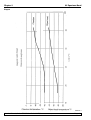
Refrigeration system
50 Hz
60 Hz
0° C to -40°C (+ 2 K / - 0 K)
Automatic hot-gas defrost cycle,
programmable in 15-min increments;
1 automatic defrost cycle per 24 hours.
Duration: 6 - 12 minutes
Manual defrost cycle
690 W
3
280 g ±5g refrigerant R 404A *
0.6 l EMKARATE RL-22S, ICI *
0° C to -40°C (+2 K / - 0 K)
Automatic hot-gas defrost cycle,
programmable in 15-min. increments;
1 automatic defrost cycle per 24 hours.
Duration: 6 - 12 minutes
Manual defrost cycle
690 W
3
280 g ±5g refrigerant R 404A*
0.6 l EMKARATE RL-22S, ICI *
Cryochamber
Temperature selection range
Defrosting
Refrigeration capacity
Safety factor
Refrigerant
Compressor oil
CM3050S-1
230 V AC ±10%
50 Hz
1800 VA
25 A eff.
I
T10A T1
2
II
1800 J/s
Quick-freeze shelf
Maximum temperature
- 43°C (+ 0 K / - 2 K)
Number of quick-freeze stations 10
Specimen cooling (Option)
Temperature range
Defrosting
Refrigeration capacity
Safety factor
Refrigerant
Compressor oil
-10° C to -50°C ±3K
Manual defrost cycle (electric)
320 W
3
185 g ±5g refrigerant R 404A *
0.4 l alpha 22, Kyodo *
or RENISO E22, Fuchs *
Service Manual / Leica CM3050 S
CM3050S-8
240 V AC ±10%
50 Hz
1800 VA
25 A eff.
I
T10A T1
2
II
1800 J/s
CM3050S-9
100 V AC ±10%
60 Hz
1800 VA
30 A eff.
I
T15A M3
2
II
1800 J/s
- 43°C (+ 0 K / - 2 K)
10
-10° C to -50°C ±3K
Manual defrost cycle (electric)
320 W
3
185 g ±5g refrigerant R 404A *
0.4 l alpha 22, Kyodo *
or RENISO E22, Fuchs *
Version 1.0 12/00 © Leica Microsystems
Page 30
Chapter 1
Introduction
*) Refrigerant and compressor oil to be
replaced only by trained and authorized
service personnel!
CM3050S-3
c-UL
120 V AC ±10%
60 Hz
1800 VA
35 A eff.
I
T15A T1
2
II
1800 J/s
CM3050S-6
208 V AC ±10%
60 Hz
1800 VA
30 A eff.
I
T12A T1
2
II
1800 J/s
CM3050S-7
230 V AC ±10%
60 Hz
1800 VA
25 A eff.
I
T10A T1
2
II
1800 J/s
Fluorescent light lamp (cryochamber illumination):
50 Hz version:
60 Hz version:
Osram Dulux S 11 W/21
Light color ‘LUMILUX hellweiß’
(brilliant white)
Osram Dulux S 13 W/21
Light color ‘LUMILUX hellweiß’
(brilliant white)
Microtome
Rotary microtome
Section thickness setting
0.5 - 300 µm
Overall specimen feed
25 mm
Vertical stroke
59 mm
Specimen retraction
50 µm
Maximum specimen size
40 x 55 mm
Specimen orientation
8° (x-, y-, z-axis)
Trimming (6 thickness settings)
5 - 150 µm
Motorized coarse feed
- slow
500 µm/s
- fast
1,000 µm/s
Sectioning motor (Option):
Sectioning speed
- slow
min.
max.
vmax
- fast
min.
max.
vmax
0.1 mm/s
100 mm/s
210 mm/s
0.1 mm/s
170 mm/s
210 mm/s
Cryocabinet
Dimensions
Width (w/o handwheel)
Width (including handwheel)
Depth
Height (arm rest level)
Overall height
800 mm
882 mm
766 mm
840 mm
1040 mm
Weight
(incl. microtome, w/o specimen cooling)
ca. 180 kg
Service Manual / Leica CM3050 S
1
according to IEC-1010, UL 3101
2
according to CECOMAF:
Liquid temperature 45°C
Evaporation temperature -25°C
Version 1.0 12/00 © Leica Microsystems
Page 31
Chapter 1
Introduction
1.3.31 Technische Daten
Betriebstemperaturbereich
(Umgebungstemperatur): +18°C bis +40°C
Alle Temperaturangaben beziehen sich
auf eine Umgebungstemperatur von
+22°C und eine relative Luftfeuchtigkeit
von maximal 60%!
Typ
Prüfzeichen
Nennspannung
Nennfrequenz
Aufnahmeleistung
Max. Anlaufstrom für 5 sec
Schutzklasse
Sicherungsautomat
Verschmutzungsgrad
Überspannungskategorie
Wärmemengeabgabe (max.)
CM3050S-10
100 V AC ±10%
50 Hz
1800 VA
35 A eff.
I
T15A M3
2
II
1800 J/s
Kälteanlage
50 Hz
60 Hz
Kälteleistung
Sicherheitsfaktor
Kältemittel
Verdichteröl
0° C bis -40°C (+ 2 K/- 0 K)
automatische Heißgasabtauung
programmierbar in 15-Minuten Schritten;
1 automatische Abtauung/24 Stunden,
Dauer: 6 - 12 Minuten
manuelle Bedarfsabtauung
690 W
3
280 g ±5g Kältemittel R 404A *
0,6 l EMKARATE RL-22S, ICI *
0° C bis -40°C (+2 K/- 0 K)
automatische Heißgasabtauung
programmierbar in 15-Minuten Schritten;
1 automatische Abtauung/24 Stunden,
Dauer: 6 - 12 Minuten
manuelle Bedarfsabtauung
690 W
3
280 g ±5g Kältemittel R 404A*
0,6 l EMKARATE RL-22S, ICI *
Schnellgefrierleiste
Maximale Temperatur
Anzahl der Gefrierstationen
- 43°C (+ 0 K/- 2 K)
10
- 43°C (+ 0 K/- 2 K)
10
-10° C bis -50°C ±3K
elektrisch
manuelle Bedarfsabtauung
320 W
3
185 g ±5g Kältemittel R 404A *
0,4 l alpha 22, Kyodo *
oder RENISO E22, Fuchs *
-10° C bis -50°C ±3K
elektrisch
manuelle Bedarfsabtauung
320 W
3
185 g ±5g Kältemittel R 404A *
0,4 l alpha 22, Kyodo *
oder RENISO E22, Fuchs *
Kryokammer
Temperaturbereich
Abtauung
Objektkühlung (Option)
Temperaturbereich
Abtauung
Kälteleistung
Sicherheitsfaktor
Kältemittel
Verdichteröl
Service Manual / Leica CM3050 S
CM3050S-1
230 V AC ±10%
50 Hz
1800 VA
25 A eff.
I
T10A T1
2
II
1800 J/s
CM3050S-8
240 V AC ±10%
50 Hz
1800 VA
25 A eff.
I
T10A T1
2
II
1800 J/s
CM3050S-9
100 V AC ±10%
60 Hz
1800 VA
30 A eff.
I
T15A M3
2
II
1800 J/s
Version 1.0 12/00 © Leica Microsystems
Page 32
Chapter 1
Introduction
*) Der Austausch des Kältemittels und
des Verdichteröls darf nur durch
autorisiertes Service Personal erfolgen!
CM3050S-3
c-UL
120 V AC ±10%
60 Hz
1800 VA
35 A eff.
I
T15A T1
2
II
1800 J/s
CM3050S-6
208 V AC ±10%
60 Hz
1800 VA
30 A eff.
I
T12A T1
2
II
1800 J/s
CM3050S-7
230 V AC ±10%
60 Hz
1800 VA
25 A eff.
I
T10A T1
2
II
1800 J/s
Leuchtstofflampe (Kammerbeleuchtung):
50 Hz-Version:
60 Hz-Version:
Osram Dulux S 11 W/21
Lichtfarbe LUMILUX hellweiß
Osram Dulux S 13 W/21
Lichtfarbe LUMILUX hellweiß
Mikrotom
Rotationsmikrotom
Schnittdickeneinstellung
0,5 - 300 µm
Objektgesamtvorschub
25 mm
Vertikalhub
59 mm
Objektrückzug
50 µm
Maximale Objektgröße
40 x 55 mm
Objektorientierung
8° (x-, y-, z-Achse)
Trimmen (in 6 Stufen)
5 - 150 µm
Elektrischer Grobtrieb
langsam
500 µm/s
schnell
1.000 µm/s
Schneidemotor (Option):
Schneidegeschwindigkeit
langsam
min.
max.
vmax
schnell
min.
max.
vmax
0,1 mm/s
100 mm/s
210 mm/s
0,1 mm/s
170 mm/s
210 mm/s
Kryostatgehäuse
Abmessungen
Breite (ohne Handrad)
Breite (mit Handrad)
Tiefe
Höhe (Armauflage)
Standhöhe
Gewicht
(inkl. Mikrotom, ohne Objektkühlung)
Service Manual / Leica CM3050 S
800 mm
882 mm
766 mm
840 mm
1040 mm
1
nach IEC-1010, UL 3101
2
nach CECOMAF
Flüssigkeitstemperatur 45°C
Verdampfungstemperatur -25°C
ca. 180 kg
Version 1.0 12/00 © Leica Microsystems
Page 33
Chapter 1
Service Manual / Leica CM3050 S
Introduction
Version 1.0 12/00 © Leica Microsystems
Page 34
Chapter 2
Chapter 2
Kapitel 2
Mechanics
Mechanik
Version 1.0
Version 1.0
Service Manual / Leica CM3050 S
Version 1.0 12/00 © Leica Microsystems
Page 1
Chapter 2
Table of Contents
Inhaltsverzeichnis
2.1 General Plan ................................................... 3
2.2 Lid ..................................................................... 4
2.3 Cryochamber, Illumination and Drain
System ............................................................. 6
2.4 Microtome ...................................................... 8
2.4.1 Removing the microtome ..................... 8
2.4.2 General plan ......................................... 10
2.4.3 Housing ................................................. 12
2.4.4 Base plate ............................................. 14
2.4.5 Cross roller bearings .......................... 16
2.4.6 Micrometer mechanism..................... 20
2.4.7 Shaft with bearing ............................... 30
2.5 Hand Drive .................................................... 32
2.6 Motor Drive .................................................. 38
2.7 Handwheel ................................................... 44
2.7.1 Handwheel - motor drive version ..... 44
2.7.2 Handwheel - hand drive version ...... 46
2.8 Orientation .................................................... 48
2.9 Heat Extractor .............................................. 52
2.1 Gesamtübersicht ........................................... 3
2.2 Haube .............................................................. 4
2.3 Kammer, Beleuchtung und Ablauf ............. 6
Service Manual / Leica CM3050 S
2.4 Mikrotom ......................................................... 8
2.4.1 Mikrotom ausbauen .............................. 8
2.4.2 Übersicht - 'Mikrotom' ....................... 10
2.4.3 Haube .................................................... 12
2.4.4 Grundplatte........................................... 14
2.4.5 Kreuzrollenführung ............................. 16
2.4.6 Mikrometerwerk .................................. 20
2.4.7 Schaft mit Lager .................................. 30
2.5 Handantrieb .................................................. 32
2.6 Motorantrieb ................................................ 38
2.7 Handrad ........................................................ 44
2.7.1 Handrad für Motorantrieb ................. 44
2.7.2 Handrad für manuellen Antrieb ........ 46
2.8 Orientierung ................................................. 48
2.9 Wärmeableitblock ....................................... 52
Version 1.0 12/00 © Leica Microsystems
Page 2
Chapter 2
2.1 General Plan
2.2
2.3
2.4
2.12
2.9
2.8
2.5
2.6
2.10
2.11
2.13
2.7
Abb.170700k1
Service Manual / Leica CM3050 S
Version 1.0 12/00 © Leica Microsystems
Page 3
19
2
12
12
11
9
3
21
6
4
20
S
50
12
13
11
13
9.2
22
ica
CM
30
Le
25
23
13
10
9.1
24
Version 1.0 12/00 © Leica Microsystems
1
11
27
19
26
Chapter 2
18
15
16
14
Service Manual / Leica CM3050 S
17
5
2.2 Lid
Page 4
Abb. 090999k1
7
Chapter 2
2..2 Lid
Disassembly - control panel, small (2)
Before performing any work on
electrical components, unplug the
instrument!
Flächentastatur, klein (2) ausbauen
Vor Arbeiten an elektrischen Bauteilen
unbedingt das Gerät vom Netz trennen.
1. Disconnect all cable connections of control
panel, small (2), see wiring diagram.
1. Sämtliche Kabelverbindungen von der Flächentastatur klein (2) trennen, siehe Kabelplan.
2. Remove nuts (12) together with tooth lock
washers (11) and washers (13).
2. Muttern (12) mit Zahnscheiben (11) und Scheiben (13) entfernen.
3. Remove the small keyboard (2) upwards.
3. Flächentastatur klein (2) nach oben abnehmen.
Disassembly - control panel, large (3)
Flächentastatur, groß (3) ausbauen
Before performing any work on
electrical components, unplug the
instrument!
1. Disconnect all cable connections of control
panel, large (3), see wiring diagram.
2. Remove nuts (12) together with tooth lock
washers (11) and washers (13).
Vor Arbeiten an elektrischen Bauteilen
unbedingt das Gerät vom Netz trennen.
1. Sämtliche Kabelverbindungen von der Flächentastatur, groß (3) trennen, siehe Kabelplan.
2. Muttern (12) mit Zahnscheiben (11) und Scheiben (13) entfernen.
3. Flächentastatur, groß (3) nach oben abnehmen.
3. Remove control panel, large (3) upwards.
Platte Netzschaltereinheit (4) ausbauen
Disassembly
- cover plate, mains switch unit (4)
Vor Arbeiten an elektrischen Bauteilen
unbedingt das Gerät vom Netz trennen.
Before performing any work on
electrical components, unplug the
instrument!
1. Unscrew screws (21) and remove cover (20).
2. Disconnect all cable connections of the mains
switch unit cover plate (4), see wiring diagram.
3. Remove nuts (12) together with tooth lock
washers (11) and washers (25).
4. Remove the mains switch unit cover plate (4)
forward.
5. Remove screws (22) and safety cutout (10).
6. Remove nut (9.2) and washer (9.1). Next, remove
safety cutout (9).
7. Remove distance bolt (24) with washers (13) and
take off filter board (23).
Service Manual / Leica CM3050 S
1. Schrauben (21) entfernen und Abdeckung (20)
abnehmen.
2. Sämtliche Kabelverbindungen an der Platte
Netzschaltereinheit (4) trennen, siehe Kabelplan.
3. Muttern (12) mit Zahnscheiben (11) und Scheiben (25) entfernen.
4. Platte Netzschaltereinheit (4) nach vorne abnehmen.
5. Schrauben (22) entfernen und Sicherungsautomat (10) abnehmen.
6. Mutter (9.2) mit Ring (9.1) entfernen und Sicherungsautomat (9) abnehmen.
7. Distanzbolzen (24) mit Scheiben (13) entfernen
und Filterplatine (23) abnehmen.
Version 1.0 12/00 © Leica Microsystems
Page 5
2.3 Cryochamber, Illumination and Drain System
Chapter 2
1
Armflex adhesive tape, thickness 3mm
Armflexband 3mm dick, selbstklebend
3
4
5
16
6
17
7
19
15
14
13
8
9
10
12
20
21
31
22
33
23
27
26
29
24
30
25
32
34
Service Manual / Leica CM3050 S
Version 1.0 12/00 © Leica Microsystems
Abb. 090999k2
Page 6
2.3 Cryochamber, Illumination and Drain System
Chapter 2
Disassembly - drain pan (19)
Ausbau Tauwasserwanne (19)
1. Remove screw (22) together with retaining
washer (21) and retaining ribbon (20).
1. Schraube (22) mit Scheibe (21) und Halteband (20) entfernen.
2. Remove the drain pan (19).
2. Tauwasserwanne (19) entnehmen.
Disassembly - guard plate (1)
Ausbau Schutzblech (1)
Before performing any work on
electrical components, unplug the
instrument!
1. Disconnect all cable connections located at the
guard plate (1), see wiring diagram.
Vor Arbeiten an elektrischen Bauteilen
unbedingt das Gerät vom Netz trennen.
1. Sämtliche Kabelverbindungen am Schutzblech
(1) trennen, siehe Kabelplan.
2. Schutzblech (1) nach oben abnehmen.
2. Remove the guard plate (1) upwards.
Ausbau Blattfeder (12)
Disassembly - leaf spring (12)
1. Schraube (14) mit Zahnscheibe (13) entfernen.
1. Remove screw (14) and tooth lock washer (13).
2. Blattfeder (12) abnehmen.
2. Take off leaf spring (12).
Ausbau Reflektor (7)
Disassembly - reflector (7)
Before performing any work on
electrical components, unplug the
instrument!
1. Disconnect all cable connections at socket (9),
see wiring diagram.
2. Remove fluorescent lamp (16) to the left.
3. Unscrew screws (3) and remove the reflector (7)
upwards.
4. Remove screws (4) and washers (5) as well as
insulating angle (10).
Vor Arbeiten an elektrischen Bauteilen
unbedingt das Gerät vom Netz trennen.
1. Sämtliche Kabelverbindungen an der Fassung
(9) trennen, siehe Kabelplan.
2. Leuchtstofflampe (16) nach links abziehen.
3. Schrauben (3) entfernen und Reflektor (7) nach
oben abnehmen.
4. Schrauben (4) mit Scheiben (5) entfernen und
Isolierwinkel (10) abnehmen.
5. Fassung (9), Halter (17) und Kabelbinder (8)
nach unten abnehmen.
5. Remove socket (9), holder (17) and cable clip (8)
downwards.
Service Manual / Leica CM3050 S
Version 1.0 12/00 © Leica Microsystems
Page 7
2.4 Microtome (2.4.1 Removing the microtome)
Chapter 2
14
13
12
4
6
11
5
16
15
4
8
1
2
3
7
Abb. 090999k3
Service Manual / Leica CM3050 S
Version 1.0 12/00 © Leica Microsystems
Page 8
2. 4 Microtome (2.4.1 Removing the microtome)
Chapter 2
Disassembly - microtome with base plate (7)
Ausbau Mikrotom mit Grundplatte (7)
1. Slightly lift the heated window (13) and pull it
out towards the front.
1. Scheibe (13) etwas anheben und nach vorne
herausziehen.
2. Pull off sensor (5) backwards.
Do not pull at the cable!
2. Sensor (5) nach hinten abziehen.
Nicht am Kabel ziehen!
3. Take the coarse feed cable (6) at the plug and
pull it to the left. Do not pull at the cable!
3. Grobtriebkabel (6) am Klinkenstecker nach
links abziehen. Nicht am Kabel ziehen!
4. On instruments with specimen cooling:
4. Bei Geräten mit Objektkühlung:
a) Remove screw (1).
a) Schraube (1) entfernen.
b) Slightly pull specimen head (4) forward.
b) Objektkopf, kpl. (4) ein wenig nach vorne
ziehen.
c) Use the specimen head fixture (11) to hang up
the specimen head (4) on the drain pan (12).
5. Remove screws (2) and saucer springs (3).
6. Turn the handwheel (14) to move the
specimen cylinder (15) to its lower end position.
7. Move the microtome with base plate (7) to the
left as far as it will go.
c) Objektkopf (4) mit Hilfe der Objektkopfhalterung (11) an der Tauwasserwanne (12)
einhängen.
5. Schrauben (2) mit Tellerfedern (3) entfernen.
6. Handrad (14) drehen, bis Zylinderführung (15)
in unterer Stellung ist.
8. Remove microtome / base plate (7) forward.
7. Mikrotom mit Grundplatte (7) nach links bis
zum Anschlag schieben.
Reinstallation - microtome / base plate (7)
8. Mikrotom / Grundplatte (7) nach vorne heraus
nehmen.
1. Reinstallation is done in reverse order.
Einbau Mikrotom mit Grundplatte (7)
2. To reconnect the components of the claw
coupling (8) the specimen cylinder (15) and the
handle of handwheel (14) must be each at their
lower end position.
Service Manual / Leica CM3050 S
1. Der Einbau erfolgt in umgekehrter Reihenfolge.
2. Beim Verbinden der Kupplungsteile (8)
müssen die Zylinderführung (15), sowie der
Griff des Handrads (14) in unterer Stellung
stehen.
Version 1.0 12/00 © Leica Microsystems
Page 9
2.4 Microtome (2.4.2 General plan)
Chapter 2
2.4.3
2.4.5
2.4.6
2.4.7
2.4.4
Abb. 090999k4
Service Manual / Leica CM3050 S
Version 1.0 12/00 © Leica Microsystems
Page 10
Chapter 2
Service Manual / Leica CM3050 S
Version 1.0 12/00 © Leica Microsystems
Page 11
Chapter 2
2.4 Mikrotome (2.4.3 Housing)
2
10
9
1
6
11
5
4
7
7
8
8
3
Abb. 090999k5
Service Manual / Leica CM3050 S
Version 1.0 12/00 © Leica Microsystems
Page 12
2.4 Mikrotome (2.4.3 Housing)
Chapter 2
Disassembly - housing (1)
Haube (1) ausbauen
1. Remove screw (3) and pull housing (1) forward
far enough so that slot cover (2) can be removed upwards.
1. Schraube (3) entfernen und Haube (1) soweit
nach vorne ziehen, bis Schlitzabdeckung (2)
nach oben entnommen werden kann.
2. Take off housing (1).
2. Haube (1) abnehmen.
Disassembly - sensor clip (6)
Sensorhalter (6) ausbauen
Before performing any work on
electrical components, unplug the
instrument!
Vor Arbeiten an elektrischen Bauteilen
unbedingt das Gerät vom Netz trennen.
1. Sensor (9) nach hinten abziehen.
Nicht am Kabel ziehen!
1. Pull off sensor (9) backwards.
Do not pull at the cable!
2. Schraube (4) mit Scheibe (5) entfernen.
2. Remove screw (4) and washer (5).
3. Sensorhalter (6) und Feder (11) abnehmen.
3. Remove sensor clip (6) and spring (11).
Sensor (9) ausbauen
Disassembly - sensor (9)
Before performing any work on
electrical components, unplug the
instrument!
1. Disconnect all cable connections at sensor (9),
see wiring diagram.
Vor Arbeiten an elektrischen Bauteilen
unbedingt das Gerät vom Netz trennen.
1. Sämtliche Kabelverbindungen am Sensor (9)
trennen, siehe Kabelplan.
2. Sensor (9) nach hinten abziehen.
Nicht am Kabel ziehen!
2. Pull off sensor (9) backwards.
Do not pull at the cable!
Grobtriebkabel (10) ausbauen
Disassembly - coarse feed cable (10)
Before performing any work on
electrical components, unplug the
instrument!
1. Disconnect all cable connections at coarse feed
cable (10), see wiring diagram.
Vor Arbeiten an elektrischen Bauteilen
unbedingt das Gerät vom Netz trennen.
1. Sämtliche Kabelverbindungen am Grobtriebkabel (10) trennen, siehe Kabelplan.
2. Grobtriebkabel (10) am Klinkenstecker nach
links abziehen. Nicht am Kabel ziehen!
2. Take coarse feed cable (10) by the jack plug and
pull it off backwards. Do not pull at the cable!
Service Manual / Leica CM3050 S
Version 1.0 12/00 © Leica Microsystems
Page 13
26
28
7
Service Manual / Leica CM3050 S
Chapter 2
23
15
19
11
6
4
2.4 Microtome (2.4.4 Base plate)
Page 14
Abb. 090999k6
5
20
28
22
13
28
8
27
14
Version 1.0 12/00 © Leica Microsystems
16
27
3
27
18
25
2.4 Microtome (2.4.4 Base plate)
Chapter 2
Disassembly - eccentric bolt (13)
Exzenterbolzen (13) ausbauen
1. Remove set screw (14).
1. Schaftschraube (14) entfernen.
2. Rotate clamping lever (16) either backward or
forward while at the same time pulling it out
sideways.
2. Spannhebel (16) nach vorne oder hinten drehen
und gleichzeitig seitlich herausziehen.
3. Remove clamping sleeve (15) and then clamping
lever (16).
3. Spannhülse (15) entfernen und Spannhebel (16)
abnehmen.
Spannbolzen (11) ausbauen
Disassembly - pulling bolt (11)
1. Remove screw (18) then remove clamping
device (23) and saucer springs (19).
1. Schraube (18) entfernen, Spannstück (23) und
Tellerfedern (19) abnehmen.
2. Exzenterbolzen (13) ausbauen, siehe oben.
2. Disassemble eccentric bolt (13), see above.
3. Spannbolzen (11) nach oben herausziehen.
3. Pull out pulling bolt (11) upwards.
4. Druckfeder (8) abnehmen.
4. Pull off pressure spring (8).
Winkel, kurz (5) ausbauen
Disassembling angle steel, short (5)
1. Detach screws (27) and remove washers (28).
1. Schrauben (27) entfernen und Scheiben (28)
abnehmen.
2. Detach screws (3), remove angle steel, short
(5) and washers (6).
2. Schrauben (3) entfernen, Winkel, kurz (5) und
Scheiben (6) abnehmen.
Disassembly - angle steel (25)
Winkel (25) ausbauen
1. Loosen screws (27) and remove washers (28).
1. Schrauben (27) entfernen und Scheiben (28)
abnehmen.
2. Remove angle steel (25) forward.
2. Winkel (25) nach vorne abnehmen.
3. Remove screws (27) and detach washers (28)
together with angle steel (26).
4. To adjust the microtome centrically to the motor
drive, move angle (25) up and down and angle
(26) back and forth. Tighten screw (22) just
slightly - it serves as a limit point.
Service Manual / Leica CM3050 S
3. Schrauben (27) entfernen, Scheiben (28)
mit Winkel (26) abnehmen.
4. Durch Verschieben des Winkels (25) auf und ab
und des Winkels (26) vor und zurück, wird das
Mikrotom zentrisch zum Motor Drive justiert. Die
Schraube (22) wird nur leicht angelegt und dient
als Ablagepunkt.
Version 1.0 12/00 © Leica Microsystems
Page 15
5Ncm
5
4
13
I
4
Version 1.0 12/00 © Leica Microsystems
6
16
III
15
6
3
3
14
Page 16
Abb. 090999k7
15
4
V
IV
2.4 Microtome (2.4.5 Cross roller bearings)
V
16
4
5Ncm
II
3
14
10
12
3
2
10
Chapter 2
1
Service Manual / Leica CM3050 S
8
2.4 Microtome (2.4.5 Cross roller bearings)
Chapter 2
Disassembly - cover plate, right (12) and
cover plate, left (13)
Abdeckblech, rechts (12) und Abdeckblech,
links (13) ausbauen
1. Unhook tensions springs (14).
1. Zugfedern (14) aushängen.
2. Detach screws (6) and remove spring
suspensions (16).
2. Schrauben (6) entfernen und Federarme (16)
abnehmen.
3. Remove spring hooks (15).
3. Federhaken (15) abnehmen.
4. Detach screws (3) and remove cover plate,
right (12) as well as cover plate, left (13).
4. Schrauben (3) entfernen; Abdeckblech rechts
(12) und Abdeckblech links (13) abnehmen.
Disassembly slider (2) and cross roller guides (10)
Ausbau des Gleitstücks (2) und der
Kreuzrollenführung (10)
1. Remove the housing (see chapter 2.4.3, item
no.1).
1. Haube kpl. entfernen, siehe Kapitel 2.4.3, Pos 1.
2. Remove specimen head (see chapter 2. 4.1, item
no. 4), slot cover (see chapter 2.4.3, item no. 2),
micrometer mechanism, assy. (see chapter 2.4.6)
and cover plates (13) and (12).
3. Place frame (1) with base plate (see chapter 2.4,
item no. 4) on its rear side. Support rear of frame
(1) with one hand while tilting it.
2. Objektkopf, siehe Kapitel 2.4.1, Pos 4, Schlitzabdeckung, siehe Kapitel 2.4.3, Pos 2, Mikrometerwerk kpl., siehe Kapitel 2.4.6 sowie Abdeckbleche kpl. (13) und (12) entfernen.
3. Gestell (1) mit Grundplatte, siehe Kapitel 2.4, Pos
4 auf die Rückseite legen. Gestell (1) dabei nach
unten abstützen.
4. Gewindestifte (5) und Sechskantmutter (8) lösen.
4. Detach setscrews (5) and hexagon nut (8).
5. Detach screws (4) which hold cross roller guide
rail (I) and remove slider (2) forward.
6. Next, remove screws (4), which hold cross roller
guide rails (II), (III) and (IV), from slider (2) and
frame (1).
Adjusting slider (2) and cross roller guides
(10)
1. Press cross roller guide rails (II) and (III) with
your fingers into the square angles at the front
side of the slider (2) and tighten screws (4).
Torque = 150 Ncm.
5. Schrauben (4) zur Kreuzrollenführungsschiene
(I) entfernen und das Gleitstück (2) kpl. nach vorne abnehmen.
6. Schrauben (4) zur Kreuzrollenführungsschienen
(II), (III) und (IV) können nun vom Gleitstück (2)
sowie Gestell (1) entfernt werden.
Justierung des Gleitstücks (2) und der
Kreuzrollenführung (10)
1. Kreuzrollenführungsschiene (II) und (III) mit den
Fingern gegen den Anschlag Innenseite Gleitstück (2) pressen und Befestigungsschrauben
(4) anziehen. Drehmoment = 150 Ncm.
2. Press cross roller guide rail (IV) into the square
angle at the front of frame (1) and fasten with
screws (4). - Torque = 150 Ncm.
2. Kreuzrollenführungsschiene (IV) gegen den Anschlag, Innenseite von Gestell (1) pressen und
Schrauben (4) anziehen. Drehmoment = 150
Ncm.
3. Place roller cages (V) in position.
3. Rollenkäfige (V) auf Position bringen.
Service Manual / Leica CM3050 S
Version 1.0 12/00 © Leica Microsystems
Page 17
5Ncm
5
4
13
I
4
Version 1.0 12/00 © Leica Microsystems
6
16
III
15
6
3
3
14
Page 18
Abb. 090999k7
15
4
V
IV
2.4 Microtome (2.4.5 Cross roller bearings)
V
16
4
5Ncm
II
3
14
10
12
3
2
10
Chapter 2
1
Service Manual / Leica CM3050 S
8
2.4 Microtome (2.4.5 Cross roller bearings)
Chapter 2
4. Insert cross roller guide rail (I) together with
slider (2).
4. Kreuzrollenführungsschiene (I) mit Gleitstück (2)
einsetzen.
5. Tighten screws (4) just slightly so they hold
cross roller guide rail (I) in position, and then
center roller cage (V).
5. Schrauben (4) zur Befestigung der Kreuzrollenführungsschiene (I) leicht anlegen und Rollenkäfig (V) vermitteln.
6. Setscrews (5) are for adjustment purposes.
The setscrews (5) are tightened using a
dynamometric key (Md = 0,5 Kpcm = 5 Ncm!).
Each time before tightening one of the
setscrews (5) make sure to position the slider (2)
right behind it so that sufficient back pressure is
provided.
6. Mit den Gewindestiften (5) wird die Einstellung
vorgenommen.
Das Anziehen der Gewindestifte (5) erfolgt mittels Drehmomentschlüssel (Md = 0,5 Kpcm = 5
Ncm!). Dabei muß das Gleitstück (2) immer hinter dem entsprechenden Gewindestift (5) stehen.
7. Tighten screws (4) which hold cross roller guide
rail (I). - Torque = 150 Ncm.
7. Schrauben (4) zu der Kreuzrollenführungsschiene (I) befestigen. Drehmoment = 150 Ncm.
Service Manual / Leica CM3050 S
Version 1.0 12/00 © Leica Microsystems
Page 19
24
3
30+- 5Ncm
4
II
30
41
200Ncm
29
12
I
30
37
13
14
26
28
9
100
27
102
16
350Ncm
15
101
32
22
31
42
8
38
34
110
38
1.1
11
Abb. 250899k1
Page 20
110
105
106
103
107
19
39
1
36
105b
11Ncm
40
34
43Ncm
200Ncm
105a
31
33
30
30
32
39
6
35
111
102
III + IV
1.2
21
2.4 Microtome (2.4.6 Micrometer mechanism)
Version 1.0 12/00 © Leica Microsystems
5
15
103
Chapter 2
Service Manual / Leica CM3050 S
29
3
Chapter 2
2.4 Microtome (2.4.6 Micrometer mechanism)
Disassembly - micrometer mechanism
Demontage des Mikrometerwerkes
1. Remove the microtome (see chapter 2.4.1).
1. Mikrotom ausbauen (siehe Kapitel 2.4.1).
2. Remove the housing (see chapter 2.4.3).
2. Haube entfernen (siehe Kapitel 2.4.3).
3. Remove six screws (26) from the front of slider
(21), pull out the entire micrometer mechanism
backwards.
3. Sechs Schrauben (26) an der Frontseite des
Gleitstücks (21) entfernen, Mikrometerwerk
komplett nach hinten herausziehen.
4. Unhook spring (19).
4. Feder (19) aushängen.
5. Loosen clamping screw (12) from the flexible
membrane coupling which clamps the stepper
motor shaft.
5. Klemmschraube von der Elast. Membrankupplung (12), welche die Schrittmotorwelle klemmt,
öffnen.
6. Remove screws (31) and washers (32), which
hold the microswitches, as well as screws (38)
and washers (39), which hold cable clamps (42
and 40).
6. Schrauben (31), Scheiben (32) zum Befestigen
der Mikroschalter sowie Schrauben (38) und
Scheiben (39) zum Befestigen der Kabelschellen (42 und 40) entfernen.
7. Remove screws (35), washers (30) and spacer
(11). Then detach the feed mechanism assembly
(2).
7. Schrauben (35), Scheiben (30), Distanzrolle (11)
entfernen und die Zustelleinheit komplett (2)
abnehmen.
8. Loosen the clamping screw of flexible
membrane coupling (12), which clamp spindle
shank (1.1).
8. Klemmschraube von der Elast. Membrankupplung (12), welche den Spindelschaft (1.1) klemmt,
öffnen.
9. Remove flexible membrane coupling (12) from
spindle shank (1.1).
9. Elast. Membrankupplung (12) von dem Spindelschaft (1.1) abziehen.
10. Loosen screw (37) and remove clamping ring
(13); saucer spring (14) and deep groove ball
bearing (15).
10. Schraube (37) öffnen und Klemmring (13) ; Tellerfeder (14), Rillenkugellager (15) abnehmen.
11. Remove screws (29) and washer (30); detach
bearing washer (5) from spindle shank (1.1).
11. Schrauben (29) und Scheibe (30) entfernen und
die Lagerscheibe (5) von dem Spindelschaft (1.1)
abnehmen.
12. Pull off deep groove ball bearing (15).
12. Rillenkugellager (15) abziehen.
13. Unscrew (9) V-ring.
13. V-Ring (9) herausdrehen.
14. Pull spindle (1.1) - together with nut (1.2), needle
bearing (16) and bushing (8) - out of cylinder (3).
14. Spindel (1.1) mit Mutter (1.2), Nadellager (16) und
Hülse (8) aus dem Zylinder (3) herausziehen.
15. Remove screw (33) and washer (34); then
remove shifting block (6).
15. Schraube (33) mit Scheibe (34) entfernen und
Schaltklotz (6) abnehmen.
16. Remove screws (27) and washers (28) and pull
ellipse (22) out of cylinder guide (4).
16. Schrauben (27) mit Scheiben (28) entfernen und
Ellipsenstück (22) aus der Zylinderführung (4)
herausziehen.
17. Pull cylinder (3) out of cylinder guide (4).
18. Remove screws (29) and washers (30); then
remove bar (24).
Service Manual / Leica CM3050 S
17. Zylinder (3) aus der Zylinderführung (4) ziehen.
18. Schrauben (29) und Scheiben (30) entfernen und
Leiste (24) abnehmen.
Version 1.0 12/00 © Leica Microsystems
Page 21
24
3
30+- 5Ncm
4
II
30
41
200Ncm
29
12
I
30
37
13
14
26
28
9
100
27
102
16
350Ncm
15
101
32
22
31
42
8
38
34
110
38
1.1
11
Abb. 250899k1
Page 22
110
105
106
103
107
19
39
1
36
105b
11Ncm
40
34
43Ncm
200Ncm
105a
31
33
30
30
32
39
6
35
111
102
III + IV
1.2
21
2.4 Microtome (2.4.6 Micrometer mechanism)
Version 1.0 12/00 © Leica Microsystems
5
15
103
Chapter 2
Service Manual / Leica CM3050 S
29
3
Chapter 2
2.4 Microtome (2.4.6 Micrometer mechanism)
Adjustment - sliding block (41)
Justierung des Kulissensteins (41)
1. Place bar (24) in its correct position; add screws
(29) and washers (30) - tighten just slightly.
1. Leiste (24) an Position bringen und die Schrauben (29) mit Scheiben (30) leicht auflegen.
2. Place sliding blocks (41) in their guide rail.
2. Kulissensteine (41) in die Führung einlegen.
Attention! Make sure the sliding blocks are
positioned correctly. The wide facet must face
downward and be located on the right; the
mark on sliding block (41) must be on the top
right.
3.) Move bar (24) up and down to adjust the
coefficient of friction.
At an ambient temperature of +23 °C the
coefficient of friction should be about 2600 g.
The coefficient of friction if temperaturedependent.
Achtung! Richtige Lage beachten. Die breite
Facette muß rechts unten sein und die Markierung an Kulissenstein (41) nach oben und rechts
schauen.
3.) Durch Verschieben der Leiste (24) nach oben
und unten wird der Reibwert justiert.
Der Reibwert soll bei einer Raumtemperatur
von +23 °C ca. 2600 g betragen. Dieser Wert ist
temperaturabhängig.
4.) Schrauben (29) festziehen, Drehmoment = 350
Ncm.
4.) Tighten screws (29). - Torque = 350 Ncm.
Montage des Mikrometerwerkes
Assembly - micrometer mechanism
1. Zylinder (3) und Zylinderführung (4) reinigen.
1. Clean cylinder (3) and cylinder guide (4).
2. Insert spindle (1.1) and nut (1.2) into cylinder (3)
and push them inward as far as they will go.
Attention! Checking the clearance of the
spindle. This check can be done only with a
completely assembled microtome. The check
should be performed at a cryochamber
temperature of approx. –25 °C.
2. Spindel (1.1) und Mutter (1.2) in den Zylinder (3)
einführen und bis zum Anschlag drücken.
Achtung! Überprüfung des Spindelspiels. Diese
Überprüfung kann nur bei einem komplett montiertem Mikrotom durchgeführt werden. Die
Boxentemperatur soll hierbei ca. –25 °C betragen.
-
Fasten the dial gauge of 0.001mm scale
division, part. no. 0178 11205, with its holder,
part no. 0800 35114, to slider (21).
Mikrometeruhr mit 0,001 mm Teilung, PartNr. 0178 11205 und Mikrometeruhrhalterung
Part- Nr. 0800 35114 am Gleitstück (21) befestigen.
-
Establish contact between the dial gauge
and cylinder (3).
Kontakt Zwischen Mikrometeruhr sowie
Zylinder (3) herstellen.
-
Press a force measuring device from the
front against cylinder (3) (with a force of
5000 g) and hold that value.
Mit einem Kraftmessgerät wird nun mit
5000 g von vorne gegen den Zylinder (3)
gedrückt und den Wert gehalten.
-
Wert auf der Mikrometeruhr notieren.
-
Log the measured value into the dial gauge.
-
-
Now use the force measuring device to pull
cylinder (3) forward at a value of 5000 g and
hold.
Mit dem Kraftmessgerät wird nun, mit einem Wert von 5000g, der Zylinder (3) nach
vorne herausgezogen, und den Wert gehalten.
-
Log that value into the dial gauge as well.
-
Wert auf der Mikrometeruhr notieren.
-
-
The difference between the two logged
values must be in the range from 5mm to
35mm
Die Differenz beider Werte soll zwischen
5mm – 35mm betragen.
-
Diese Überprüfung soll an verschiedenen
Spindel- / Mutterpositionen wiederholt
werden.
-
-
-
This check has to be repeated at several
different spindle / nut positions.
Service Manual / Leica CM3050 S
Version 1.0 12/00 © Leica Microsystems
Page 23
24
3
30+- 5Ncm
4
II
30
41
200Ncm
29
12
I
30
37
13
26
5
28
15
9
100
27
102
16
350Ncm
15
101
32
22
31
42
8
38
34
110
38
1.1
11
Abb. 250899k1
Page 24
110
105
106
103
107
19
39
1
36
105b
11Ncm
40
34
43Ncm
200Ncm
105a
31
33
30
30
32
39
6
35
111
102
III + IV
1.2
21
2.4 Microtome (2.4.6 Micrometer mechanism)
Version 1.0 12/00 © Leica Microsystems
14
103
Chapter 2
Service Manual / Leica CM3050 S
29
3
Chapter 2
2.4 Microtome (2.4.6 Micrometer mechanism)
3. Assemble bushing (8) and needle bearing (16)
and insert as far as it will go.
3. Hülse (8) und Nadellager (16) montieren und bis
zum Anschlag einführen.
4. Use tool part no. 0800 29276 to screw V-Ring (9)
into cylinder (3) as far as it will go.
4. V-Ring (9) mit einem Werkzeug
Part-Nr. 0800 29276 bis zum Anschlag in den
Zylinder (3) eindrehen.
5. Clean and lubricate the bearing surface of
cylinder guide (4).
6. Clean and lubricate the bearing surface of
cylinder (3) and insert cylinder (3) into cylinder
guide (4).
5. Lauffläche von der Zylinderführung (4) reinigen
und einfetten.
6. Zylinderlauffläche (3) reinigen, fetten und Zylinder (3) in die Zylinderführung (4) einführen.
7. Fasten shifting block (6), screw (33) and washer
(34) to cylinder (3) such that they are parallel to
the opening for the cylinder guide. - Torque = 43
± 1Ncm.
7. Schaltklotz (6) mit der Schraube (33) und Scheibe (34) an den Zylinder (3) parallel zur Zylinderführaussparung befestigen, Drehmoment = 43 ±
1Ncm.
8. Place ellipse (22) in correct position. Tighten
screws (27) and washers (28) just slightly: ellipse
(22) must still be movable.
8. Ellipsenstück (22) an Position bringen. Schrauben (27) und Scheiben (28) leicht anlegen, das
Ellipsenstück (22) muß sich noch bewegen lassen.
9. Adjust the ellipse (rotate counterclockwise as
far as it will go), so that a friction of 2.2 to 2.7 kg
can be measured, (friction I). Measuring point:
cylinder.
10. Tighten screws (27). Torque = 350 Ncm.
11. Lubricate ball bearing (15) and slide onto spindle
(1.1) as far as it will go.
12. Position bearing washer (5) correctly and fasten
screws (29) and washers (30) just slightly.
13. Slide tool, part no. 0800 29274, onto the shank of
spindle (1.1) and center bearing washer (5).
Tighten screws (29) crosswise. - Torque = 200
Ncm.
14. Slide ball bearing (15) (lubricated) and saucer
springs (14) onto the shank of spindle (1.1); use
tool, part no. 0800 29273 to screw clamping ring
(13) onto spindle (1.1).
Attention! The clamping ring has to be
tightened at a torque of 30 ± 5Ncm.
Torque value II. Make sure the saucer springs
are positioned correctly.
9. Ellipsenstück justieren (gegen Uhrzeigersinn bis
Anschlag drehen), so daß man einen Reibwert
von 2,2 bis 2,7 kg messen kann, (Reibwert I). Messpunkt: Zylinder.
10. Schrauben (27) anziehen. Drehmoment = 350 Ncm.
11. Kugellager (15) fetten und auf Spindel (1.1) bis
Anschlag schieben.
12. Lagerscheibe (5) an Position bringen und
Schrauben (29) und Scheiben (30) leicht anlegen.
13. Werkzeug Part-Nr. 0800 29274 auf den Schaft der
Spindel (1.1) schieben und die Lagerscheibe (5)
zentrisch justieren. Schrauben (29) über Kreuz
festziehen. Drehmoment = 200 Ncm.
14. Kugellager (15) gefettet und Tellerfedern (14)
über den Schaft der Spindel (1.1) schieben und
mit dem Werkzeug Part-Nr. 0800 29273 den
Klemmring (13) auf die Spindel (1.1) drehen.
Achtung! Der Klemmring muß mit einem Drehmoment von 30 ± 5Ncm. angezogen werden.
Drehmomentwert II. Auf korrekte Lage der
Tellerfedern ist zu achten.
15. Tighten screw (37).
16. Torque of spindle rotation may be 6 Ncm max.!
Measuring point: hexagon socket inside the
spindle shank. - Torque value III.
17. Install flexible membrane coupling (12) (push
against limit stop) and fasten with screw.
18. Place feed mechanism assembly (2) in correct
position.
15. Schraube (37) festziehen.
16. Der Drehmoment der Spindeldrehung darf max.
6 Ncm. betragen . Messpunkt: Innensechskant
im Spindelschaft. Drehmomentwert III.
17. Elast. Membrankupplung (12) montieren (gegen
Anschlag drücken) und mit der Schraube befestigen.
18. Zustelleinheit kpl. (2) an Position bringen.
Service Manual / Leica CM3050 S
Version 1.0 12/00 © Leica Microsystems
Page 25
24
3
30+- 5Ncm
4
II
30
41
200Ncm
29
12
I
30
37
13
14
26
28
9
100
27
102
16
350Ncm
15
101
32
22
31
42
8
38
34
110
38
1.1
11
Abb. 250899k1
Page 26
110
105
106
103
107
19
39
1
36
105b
11Ncm
40
34
43Ncm
200Ncm
105a
31
33
30
30
32
39
6
35
111
102
III + IV
1.2
21
2.4 Microtome (2.4.6 Micrometer mechanism)
Version 1.0 12/00 © Leica Microsystems
5
15
103
Chapter 2
Service Manual / Leica CM3050 S
29
3
Chapter 2
2.4 Microtome (2.4.6 Micrometer mechanism)
19. Assemble spacers (11) and fasten screws (35)
and washers (30) just slightly.
19. Distanzrollen (11) montieren und Schrauben (35)
Scheiben (30) leicht anlegen.
20. Center feed mechanism assembly (2) (shift
until centered) and tighten screws (35)
crosswise. Torque = 200 Ncm.
20. Zustelleinheit kpl. (2) durch Verschieben zentrisch justieren und die Schrauben (35) über
Kreuz anziehen, Drehmoment = 200 Ncm.
21. Tighten the screws of the flexible membrane
coupling.
21. Schrauben der Elast. Membrankupplung festziehen.
22. Install both microswitches (2.2) parallel to the
cylinder guide (4) and fasten with screws (31)
and washers (32). - Torque = 11 ± 1 Ncm.
22. Beide Mikroschalter (2.2) parallel zur Zylinderführung (4) montieren und den Schrauben (31) und
Scheiben (32) befestigen, Drehmoment = 11 ± 1
Ncm.
23. Put cable clamps (40 and 42) in correct position
and fasten with screws (38) and washers (39).
24. Hook in tension spring (19).
25. Measure torque IV.
23. Kabelschelle (40 und 42) an Position bringen und
mit den Schrauben (38) und Scheiben (39) befestigen.
24. Zugfeder (19) einhängen.
Attention! Torque IV is temperature-dependent
and may be max. (see table below).
25. Drehmoment IV messen.
- 25°C
-> 12Ncm
Achtung! Der Drehmoment IV ist temperaturabhängig und darf max. bei bestimmten Temperatur betragen.
- 35°C
-> 15Ncm
+ 23°C -> 10Ncm
+ 23°C -> 10Ncm
It is absolutely necessary to verify these values,
as values exceeding those listed above may
lead to problems in the feed mechanism.
26. Insert the micrometer mechanism assembly
from the back into the opening in slider (21) and
fasten it with screws (26).
- 25°C
-> 12Ncm
- 35°C
-> 15Ncm
Diese Werte müssen unbedingt überprüft werden, da bei einem erhöhten Wert Zustellprobleme auftreten können.
Attention! Make sure the micrometer
mechanism is exactly centered (adjust if
necessary)!
26. Mikrometerwerk kpl. von hinten in die Bohrung
des Gleitstücks (21) einführen und mit den sechs
Schrauben (26) befestigen.
27. Install the microtome in the chamber and cool
down.
Achtung! Auf eine zentrische Justierung ist zu
achten.
28. Do final check.
27. Mikrotom einbauen und abkühlen.
Attention! The final check must be performed at
a cryochamber temperature of approx. -25°C
and must include the following steps:
Service Manual / Leica CM3050 S
28. Endtest durchführen.
Achtung! Beim Endtest müssen unbedingt
folgende Werte überprüft werden.
Voraussetzung dafür ist eine Boxtemperatur von
ca. – 25°C.
Version 1.0 12/00 © Leica Microsystems
Page 27
24
3
30+- 5Ncm
4
II
30
41
200Ncm
29
12
I
30
37
13
26
5
28
15
9
100
27
102
16
350Ncm
15
101
32
22
31
42
8
38
34
110
38
1.1
11
Abb. 250899k1
Page 28
110
105
106
103
107
19
39
1
36
105b
11Ncm
40
34
43Ncm
200Ncm
105a
31
33
30
30
32
39
6
35
111
102
III + IV
1.2
21
2.4 Microtome (2.4.6 Micrometer mechanism)
Version 1.0 12/00 © Leica Microsystems
14
103
Chapter 2
Service Manual / Leica CM3050 S
29
3
2.4 Microtome (2.4.6 Micrometer mechanism)
Chapter 2
- Check the feed mechanism. For that purpose,
mount dial gauge, part no. 0178 11205 and dial
gauge holder, part no. 0800 35114. Subsequently
(via the electronics), set the feed thickness
values listed below. Perform 10 handwheel
rotations at each setting. After each sequence
of 10 rotations, the following feed values have to
be measured:
- Überprüfung der Zustellung . Dafür muß die
Mikrometeruhr Part-Nr 0178 11205, sowie der
Mikrometeruhrhalter Part-Nr 0800 35114
montiert werden. Über die Elektronik werden
hiernach folgende Zustellwerte einzeln eingestellt. Bei jeweils 10 Umdrehungen mit
dem Handrad müssen folgende Zustellwerte
gemessen werden.
1µm
->
14
-
16µm
1µm
->
14
-
16µm
2µm
->
23
-
27µm
2µm
->
23
-
27µm
5µm
->
45
-
55µm
5µm
->
45
-
55µm
10µm
->
90
- 110µm
10µm
->
90
- 110µm
When doing these measurements, the specimen
cooling must be “OFF”.
Bei diesen Messungen muß die Objektkopfkühlung “AUS” sein.
-
Retraction of the micrometer mechanism
has to be 50µm ± 20µm.
-
Der Rückzug des Mikrometerwerkes soll
50µm ± 20µm betragen.
-
Coarse feed travel time 'Fast forward/
backward' from 'Home' to 'Stop' has to be
20 - 24sec.
-
Die schnelle Vor/Rücklauf-Geschwindigkeit
des Grobtriebes von Home bis Stopposition
soll 20 - 24sek betragen.
Service Manual / Leica CM3050 S
Version 1.0 12/00 © Leica Microsystems
Page 29
Chapter 2
6
8
10
9
14
15.2
5
2.4 Microtome (2.4.7 Shaft with bearing)
11
Version 1.0 12/00 © Leica Microsystems
3
Page 30
Abb. 141200k1
1
14
13
15.1
17
15.3
Service Manual / Leica CM3050 S
2
15
7
4
7
12
2.4 Microtome (2.4.7 Shaft with bearing)
Chapter 2
Disassembly - shaft, assy. (6)
Welle, kpl. (6) ausbauen
1. Detach screws (14) and remove clutch (15)
together with clutch components (15.1) and
(15.2).
1. Schrauben (14) öffnen und Kupplung (15) mit
Kupplungsteilen (15.1) und (15.2) abnehmen.
2. Remove dowel pin (13) and then ring (18)
together with washer (7).
2. Spannstift (13) entfernen und Ring (18) mit
Scheibe (7) abnehmen.
3. Schrauben (11) mit Scheiben (10) entfernen.
3. Remove screws (11) with washers (10).
4. Pull off bearing flange (9). Slide bearing (12) is
friction-set into bearing flange (9).
4. Lagerflansch (9) abziehen. Gleitlager (12) ist in
Lagerflansch (9) eingepresst.
5. Kugellager (8) und Scheibe (7) abziehen.
5. Pull off deep groove ball bearing (8) and washer
(7).
6. Pull out shaft, assy. (6) sideways, then remove
pin (17) and sliding block (5).
7. See chapter 2.4.6 on how to adjust sliding block
(5).
6. Welle (6) seitlich herausziehen, Stift (17) und Kulissenstein (5) entfernen.
7. Justierung des Kulissensteins (5), siehe Kapitel
2.4.6.
8. Die Montage erfolgt in umgekehrter Reihenfolge.
8. To reassemble, proceed in reverse order.
Gestell (4) ausbauen
Disassembly - frame (4)
1. Schraube (3) und Federscheibe (2) entfernen.
1. Remove screw (3) and spring washer (2).
2. Gestell (4) abnehmen.
2. Detach frame (4).
Service Manual / Leica CM3050 S
Version 1.0 12/00 © Leica Microsystems
Page 31
22
Chapter 2
Service Manual / Leica CM3050 S
29
19
2
28
20
3
6
21
15
25
27
3
1
7
14
10
23
4
8
7
26
24
11
2
3
4
9
Version 1.0 12/00 © Leica Microsystems
12
3
58
57
54
17
13
55
34
3
29
33
56
22
35
28
37
4
3
21
25
23
44
26
31
27
39
35
24
52
42
38
36
32
4
50
49
3
48
47
51
43
60
60
46
Abb. 960716r2
Page 32
41
40
45
33
2.5 Hand Drive
11
2.5 Hand Drive
Chapter 2
Disassembly - handwheel assy.
Handantrieb kpl. ausbauen
Before performing any work on
electrical components, unplug the
instrument!
1. Disconnect the cable connections at
microswitch (26) and precision potentiometer
(48), see chapter 'Electronics'.
2. Remove screws (2) and retaining washers (3)
from handwheel assy. mounting plate (1).
3. Remove hexagon nuts (4) and washers (3) from
mounting plate (1).
4. Unhook toothed belt (52) and detach mounting
plate (1).
Disassembly - precision potentiometer (48)
1. Loosen setscrew (47) and remove spur wheel
(46).
Vor Arbeiten an elektrischen Bauteilen
unbedingt das Gerät vom Netz trennen.
1. Kabelverbindungen an Mikroschalter (26) und
Präzisionspotentiometer (48) trennen, siehe Kapitel Elektronik.
2. Schrauben (2) mit Sicherungsscheiben (3) an
Handradplatine (1) entfernen.
3. Muttern (4) mit Sicherungsscheiben (3) von
Handradplatine (1) entfernen.
4. Zahnriemen (52) aushängen und Handradplatine
(1) abnehmen.
Präzisionspotentiomenter (48) ausbauen
1. Gewindestift (47) lösen und Stirnrad (46) abziehen.
2. Schrauben (33) mit Scheiben (45) entfernen.
2. Remove screws (33) and washers (45).
3. Remove precision potentiometer (48) from potentiometer elbow (43) .
3. Präzisionspotentiometer (48) von Potiwinkel (43)
abnehmen.
Lagerflansch (32) ausbauen
Disassembly - bearing flange (32)
1. Remove locking washer (11) from primary shaft
(38).
1. Sicherungsring (11) von Antriebswelle (38) entfernen.
2. Gewindestift (44) lösen.
2. Detach setscrew (44).
3. Remove toothed wheel (42) and tooth lock
washer Z5.1 (40).
4. Remove locking washer (37) and pull off primary
shaft (38) forward.
3. Zahnrad (42) mit Zahnscheibe Z5.1 (40) abnehmen.
4. Sicherungsring (37) entfernen und Antriebswelle
(38) nach vorne abziehen.
5. Remove bearing flange (32) from bearing plate
(31).
5. Lagerflansch (32) von Lagerplatte (31) abziehen.
6. Remove both deep groove ball bearings (35)
together with levelling washer (36).
6. Beide Rillenkugellager (35) abziehen und Ausgleichscheibe (36) entnehmen.
Keep in mind when reassembling:
Beim Einbau beachten!
1. Bearing flange (32) has to be glued
into bearing plate (31) with Loctite 638.
1. Lagerflansch (32) mit Loctite 638 in
die Lagerplatte (31) einkleben.
2. In case that toothed wheel (42) had
been removed from tooth lock washer
(40), screws (41) have to be glued into
tooth lock washer (40) with Loctite 638.
2. Wurde das Zahnrad (42) von der Zahnscheibe (40) abgenommen, so sind die
Schrauben (41) mit Loctite 638 in die
Zahnscheibe (40) einzukleben.
Service Manual / Leica CM3050 S
Version 1.0 12/00 © Leica Microsystems
Page 33
22
Chapter 2
Service Manual / Leica CM3050 S
29
19
2
28
20
3
6
21
15
25
27
3
1
7
14
10
23
4
8
7
26
24
11
2
3
4
9
Version 1.0 12/00 © Leica Microsystems
12
3
58
57
54
17
13
55
34
3
29
33
56
22
35
28
37
4
3
21
25
23
44
26
31
27
39
35
24
52
42
38
36
32
4
50
49
3
48
47
51
43
60
60
46
Abb. 960716r2
Page 34
41
40
45
33
2.5 Hand Drive
11
2.5 Hand Drive
Chapter 2
Disassembly - roller (54)
Laufrolle (54) ausbauen
1. Remove screw (56) and retaining washer (3).
1. Schraube (56) mit Scheibe (3) entfernen.
2. Remove tenon block (58) and axle (57).
2. Nutenstein (58) mit Achse (57) entnehmen.
3. Remove deep groove ball bearing (55) from roller
(54). - Attention - secured with Loctite 638!
3. Rillenkugellager (55) von Laufrolle (54) abziehen.
Achtung mit Loctite 638 gesichert!
Disassembly - switch holder (21)
Schalterplatte (21) ausbauen
1. Remove screws (24) and locking washers (23).
1. Schrauben (24) mit Scheiben (23) entfernen.
2. Remove switch holder (21) with components.
2. Schalterplatte (21) mit Bauteilen entnehmen.
3. Unhook tension spring (28).
3. Zugfeder (28) aushängen.
4. Detach screw (29) and remove switch lever (22).
4. Schraube (29) entfernen und Schalthebel (22)
entnehmen.
5. Remove screws (27) and microswitch (26).
5. Schrauben (27) entfernen und Mikroschalter (26)
entnehmen.
6. Remove grooved pin (25).
Keep in mind when reassembling:
1. Screw (29) has to be glued into
switch holder (21) with Loctite 638.
2. Switch lever (22) has to be smoothrunning but free from play.
6. Kerbstift (25) entfernen.
Beim Einbau beachten!
1. Schraube (29) mit Loctite 638 in
Schalterplatte (21) einkleben.
2. Schalthebel (22) muß leichtgängig
und spielfrei sein.
Disassembly - axle (6)
1. Remove hexagon nut (19) and washer (20).
Achse (6) ausbauen
2. Detach axle (6) and attached components and
remove forward.
1. Mutter (19) mit Scheibe (20) entfernen.
2. Achse (6) mit Bauteilen nach vorne abnehmen.
3. Remove locking washers (14 and 11).
3. Sicherungsringe (14 und 11) entfernen.
4. Remove washer (10), levelling washer (9) and
levelling washer (15).
5. Pull off wheel hub (12) and crown gear (13)
towards the front.
Service Manual / Leica CM3050 S
4. Scheibe (10), Ausgleichscheibe (9) und Ausgleichscheibe (15) abnehmen.
5. Nabe (12) mit Zahnriemenrad (13) nach vorne
abziehen.
Version 1.0 12/00 © Leica Microsystems
Page 35
22
Chapter 2
Service Manual / Leica CM3050 S
29
19
2
28
20
3
6
21
15
25
27
3
1
7
14
10
23
4
8
7
26
24
11
2
3
4
9
Version 1.0 12/00 © Leica Microsystems
12
3
58
57
54
17
13
55
34
3
29
33
56
22
35
28
37
4
3
21
25
23
44
26
31
27
39
35
24
52
42
38
36
32
4
50
49
3
48
47
51
43
60
60
46
Abb. 960716r2
Page 36
41
40
45
33
2.5 Hand Drive
11
Chapter 2
2.5 Hand Drive
6. Remove both deep groove ball bearings (7) and
then bush (8).
6. Beide Rillenkugellager (7) abziehen und Hülse
(8) entnehmen.
Keep in mind when reassembling:
Beim Einbau beachten!
1. In case crown gear (13) had been
removed from wheel hub (12), crown
gear (13) has to be glued onto wheel
hub (12) with Loctite 638.
1. Wurde das Zahnriemenrad (13) von
der Nabe (12) abgenommen, ist beim
Zusammenbau das Zahnrienrad (13)
mit Loctite 638 auf die Nabe (12)
aufzukleben.
2. In case parallel pin (17) had been
pulled out, it has to be glued into
wheel hub (12) with Loctite 638.
Service Manual / Leica CM3050 S
2. Wurde der Zylinderstift (17)
abgezogen, ist dieser beim
Zusammenbau mit Loctite 638 in die
Nabe (12) einzukleben.
Version 1.0 12/00 © Leica Microsystems
Page 37
Chapter 2
Service Manual / Leica CM3050 S
52
48
48a
20
64
65
66
62
5
61
48b
50
Version 1.0 12/00 © Leica Microsystems
49
10
2
23
41
25
40
1
3
28
12
6
39
26
11
39
24
37
21
8
22
42
7
41
40
29
46
14
18
54 59
56
34
18
35
15
57
3
18
19
16
10 31
Page 38
Abb. 960717r2
44
3
43
33
18
2
45
30
3
2.6 Motor Drive
20
17
38
Chapter 2
2.6 Motor Drive
Disassembly - motor drive, cpl.
Motorantrieb kpl. ausbauen
Before performing any work on
electrical components, unplug the
instrument!
1. Disconnect the cable connection at the motor
(5), see chapter 'Electronics'.
2. Disconnect cable connection at the bearing
block (28), see chapter 'Electronics'.
Vor Arbeiten an elektrischen Bauteilen
unbedingt das Gerät vom Netz trennen.
1. Kabelverbindung am Motor (5) trennen, siehe
Kapitel Elektronik.
2. Kabelverbindung am Lagerblock (28) trennen,
siehe Kapitel Elektronik.
3. Schraube, siehe Kapitel 2.5, Pos 56 lösen.
3. Detach screw (see chapter 2.5, item no. 56).
4. Slightly push roller (see chapter 2.5, item no. 54)
downwards and unhook toothed belt (44).
4. Laufrolle, siehe Kapitel 2.5, Pos 54 etwas nach
unten drücken und Zahnriemen (44) aushängen.
5. Muttern (2) mit Scheiben (3) entfernen.
5. Remove nuts (2) and retaining washers (3).
6. Remove mounting plate (1) with all attached
components.
6. Getriebeplatte (1) komplett mit allen Bauteilen
abnehmen.
Motor (5) ausbauen
Disassembly - motor (5)
1. Remove screws (7), locking washers (8) and distance sleeves (6).
1. Schrauben (7), Scheiben (8) und Distanzhülsen
(6) entfernen.
3. Motor (5) nach hinten abnehmen.
3. Remove motor (5) towards the rear.
4. Zahnriemen (12) abnehmen.
4. Take off toothed belt (12).
5. Remove setscrew (10) and then tooth lock
washer Z1 (11).
5. Gewindestift (10) lösen und Zahnscheibe (11)
abnehmen.
6. Schrauben (64) entfernen.
6. Detach screws (64).
7. Pull off connector (65) and distance sleeve (66).
7. Steckverbinder (65) mit Distanzbolzen (66) abnehmen.
Lagerblock (28) ausbauen
Disassembly - bearing block (28)
1. Sicherungsring (45) entfernen.
1. Take off locking washer (45).
2. Loosen setscrew (10) take off tooth lock washer
Z5 (43).
2. Gewindestift (10) lösen und Zahnscheibe (43)
abnehmen.
3. Muttern (31) mit Scheiben (3) entfernen.
3. Remove nuts (31) with retaining washers (3).
4. Zahnriemen (26) aushängen.
4. Unhook toothed belt (26).
5. Remove the entire bearing block with all
attached components (28).
6. Loosen setscrew (52) and remove
electromagnetic clutch (48).
Service Manual / Leica CM3050 S
5. Lagerblock (28) komplett mit allen Bauteilen abnehmen.
6. Gewindestift (52) lösen und Kupplungslamelle
(48) abnehmen.
Version 1.0 12/00 © Leica Microsystems
Page 39
Chapter 2
Service Manual / Leica CM3050 S
52
48
48a
20
64
65
66
62
5
61
48b
50
Version 1.0 12/00 © Leica Microsystems
49
10
2
23
41
25
40
1
3
28
12
6
39
26
11
39
24
37
21
8
22
42
7
41
40
29
46
14
18
54 59
56
34
18
35
15
57
3
20
18
19
16
17
10 31
43
33
18
2
45
30
3
2.6 Motor Drive
Page 40
Abb. 960717r2
44
3
38
2.6 Motor Drive
Chapter 2
7. Take off locking washer (20) and remove clutch
intermediary (48a) with adjusting washer (50).
7. Sicherungsring (20) entfernen und Kupplungszwischenteil (48a) mit Paßscheibe (50) abnehmen.
8. Remove screws (61) and washers (62).
8. Schrauben (61) mit Scheiben (62) entfernen.
9. Remove lower half (48b) of the clutch.
9. Kupplungsunterteil (48b) abnehmen.
10. Remove locking washer (40) and washers (39).
10. Sicherungsring (40) mit Scheiben (39) entfernen.
11. Pull off bearing bush (37) and clutch shaft (33)
forward.
11. Lagerhülse (37) mit Kupplungswelle (33) nach
vorne abziehen.
12. Pull off deep groove ball bearing (41) from
bearing block (28).
12. Rillenkugellager (41) von Lagerblock (28) abziehen.
13. Detach locking washer (35) with deep groove
ball bearing (18) and levelling disc (34).
13. Sicherungsring (35) mit Kugellager (18) und Kugellagerausgleichsscheibe (34) entfernen.
14. Pull off clutch shaft (33) forward.
14. Kupplungswelle (33) nach vorne abziehen.
15. Detach deep groove ball bearing (18) with tooth
lock washer Z4 (38).
15. Kugellager (18) mit Zahnscheibe (38) abziehen.
16. Remove locking washer (40) and take off
levelling disc (42) and washer (39).
16. Sicherungsring (40) entfernen und Kugellagerausgleichsscheibe (42) mit Scheibe (39) entnehmen.
Remember when reassembling:
Beim Einbau beachten!
1. The intermediary part (48a) of the
clutch may have a maximum axial
play of 0.2 mm. If this is not the case,
compensate with adjusting washer
(50).
1. Kupplungszwischenteil (48a) darf ein
max. Axialspiel von 0,2mm
aufweisen, ggf. mit Paßscheibe (50)
ausgleichen.
2. In case the threaded rods (30) had
been loosened, they have to be glued
into the bearing block (28) with
Loctite 638.
2. Falls die Gewindestangen (30) gelöst
wurden, sind diese mit Loctite 638 in
den Lagerblock (28) einzukleben.
3. Die Zahnscheibe (38) mit Loctite 638
auf die Lagerhülse (37) kleben.
3. Glue tooth lock washer Z4 (38) onto
bearing bush (37) with Loctite 638.
Ausbau der Laufrolle (54)
Disassembly - roller (54)
1. Schraube (57) mit Scheibe (3) entfernen.
1. Remove screw (57) and retaining washer (3).
2. Laufrolle (54) mit Rillenkugellager (56) und Achse
(59) entnehmen.
Achtung, Rillenkugellager (56) ist in die Laufrolle (54) mit Loctite 638 eingeklebt.
2. Take out roller (54) with deep groove ball
bearing (56) and axle (59).
Attention, deep groove ball bearing (56) is glued
into roller (54) with Loctite 638.
3. Kugellager (56) mit Achse (59) von Laufrolle (54)
abziehen.
3. Pull ball bearing (56) / axle (59) out of roller (54).
Service Manual / Leica CM3050 S
Version 1.0 12/00 © Leica Microsystems
Page 41
Chapter 2
Service Manual / Leica CM3050 S
52
48
48a
20
64
65
66
62
5
61
48b
50
Version 1.0 12/00 © Leica Microsystems
49
10
2
23
41
25
40
1
3
28
12
6
39
26
11
39
24
37
21
8
22
42
7
41
40
29
46
14
18
54 59
56
34
18
35
15
57
3
20
18
19
16
17
10 31
Abb. 960717r2
Page 42
43
33
18
2
45
30
3
2.6 Motor Drive
44
3
38
2.6 Motor Drive
Chapter 2
Disassembly - bearing flange (15)
Ausbau des Lagerflansches (15)
1. Remove locking washer (20) and then pull out to
the rear intermediary axle (21) with tooth lock
washer Z2 and Z3 (22 and 24).
1. Sicherungsring (20) entfernen und Zwischenradachse (21) mit Zahnscheiben (22 und 24) nach
hinten herausziehen.
2. Take off deep groove ball bearing (18) and
remove levelling washer (19).
2. Kugellager (18) abziehen und Ausgleichscheibe
(19) entfernen.
3. Remove screws (16) with washers (17) and
detach bearing plate (14).
3. Schrauben (16) mit Scheiben (17) entfernen und
Lagerplatte (14) abnehmen.
4. Pull off deep groove ball bearing (18).
4. Kugellager (18) abziehen.
Keep in mind when reassembling:
Beim Einbau beachten!
1. Glue bearing flange (15) into bearing
plate (14) with Loctite 638.
1. Lagerflansch (15) mit Loctite 638 in
Lagerplatte (14) einkleben.
Disassembly tooth lock washers (22 and 24)
Ausbau der Zahnscheiben (22 und 24)
1. Remove locking washer (25) and parallel pin
(23).
1. Sicherungsring (25) und Zylinderstift (23) entfernen
2. Detach tooth lock washers (22 and 24) from intermediary axle (21).
2. Zahnscheiben (22 und 24) von Zwischenradachse (21) abziehen.
Keep in mind when reassembling:
Beim Einbau beachten!
1. Glue tooth lock washer (22) onto
intermediary axle (21) with Loctite
638.
1. Zahnscheibe (22) mit Loctite 638 auf
Zwischenradachse (21) kleben.
Service Manual / Leica CM3050 S
Version 1.0 12/00 © Leica Microsystems
Page 43
Chapter 2
2
6
11
12
22
Version 1.0 12/00 © Leica Microsystems
9
23
24
25
27
19
26
Page 44
Abb. 960717r1
2.7 Handwheel (2.7.1 Handwheel for motor drive version)
14
13
20
18
5
10
8
7
3
4
Service Manual / Leica CM3050 S
1
15
16
17
Chapter 2
2.7 Handwheel (2.7.1 Handwheel for motor drive version)
Detaching the handwheel
Handrad abschrauben
1. Remove cover disc (19).
1. Abdeckscheibe (19) entfernen.
2. Unscrew screw (16) from axle (see chapter 2.5,
item no. 6).
2. Schraube (16) aus Achse, siehe Kapitel 2.5, Pos
6 herausdrehen.
3. Remove handwheel (10).
3. Handrad (10) abnehmen.
Disassembly - handwheel
Handrad zerlegen
1. Remove hexagon nuts (7 and 8) with discs (9).
1. Muttern (7 u. 8) mit Scheiben (9) entfernen.
2. Detach plate (18) to the front, remove screws
(27) and washer (20).
2. Teller (18) nach vorne abnehmen, Schraube (27)
und Scheibe (20) entfernen.
3. Take off sliding pin (12), washer (13), disc (17),
screw (16) and conical spring washer (15).
3. Gleitstift (12), Scheibe (13), Scheibe (17), Schraube (16) und Spannscheibe (15) entfernen.
4. Remove screws (14) and pull off handle, assy.
(26).
4. Schrauben (14) entfernen und Griff (26) kpl. abziehen.
5. Unscrew shaft (22), washer (23), pressure spring
(24) and bearing (25) from handle (26).
5. Welle (22), Scheibe (23), Druckfeder (24) und
Lager (25) von Griff (26) abschrauben.
6. Remove screws (11) and detach bearing (2).
6. Schrauben (11) entfernen und Lager (2) abnehmen.
7. Remove screw (6) with hexagon nut (4) and
locking washer (3).
7. Schraube (6) mit Mutter (4) und Scheibe (3) entfernen.
8. Take off leaf spring (5) and bolt (1).
8. Blattfeder (5) und Bolzen (1) abnehmen.
Remember when reassembling:
1. Shaft (22) is glued into handle (26)
with Loctite 274.
Service Manual / Leica CM3050 S
Beim Einbau beachten!
1. Die Welle (22) wird mit Loctite 601 in
den Griff (26) eingeklebt.
Version 1.0 12/00 © Leica Microsystems
Page 45
Chapter 2
4
Service Manual / Leica CM3050 S
1
3
6
2
5
15
9
10
11
Page 46
Abb. 960919k5
12
2.7 Handwheel (2.7.2 Handwheel for hand drive version)
8
Version 1.0 12/00 © Leica Microsystems
7
Chapter 2
2.7 Handwheel (2.7.2 Handwheel for hand drive version)
Detaching the handwheel
Handrad abschrauben
1. Remove cover disc (12).
1. Abdeckscheibe (12) entfernen.
2. Remove screw (11) and conical spring washer (10).
2. Schraube (11) und Spannscheibe (10) entfernen.
3. Take off handwheel (9).
3. Handrad (9) abnehmen.
Disassembly - handwheel
Handrad zerlegen
1. Unscrew handle (15) from the back using an
Allen key.
1. Griff (15) von hinten mit einem Innensechskantschraubenschlüssel abschrauben.
2. Remove screw (7) and locking washer (8).
2. Schraube (7) mit Scheibe (8) entfernen.
3. Take off bearing (2).
3. Lager (2) abnehmen.
4. Remove screw (6) with hexagon nut (4) and
locking washer (3).
4. Schraube (6) mit Mutter (4) und Scheibe (3) entfernen.
5. Remove leaf spring (5) and bolt (1).
5. Blattfeder (5) und Bolzen (1) abnehmen.
Service Manual / Leica CM3050 S
Version 1.0 12/00 © Leica Microsystems
Page 47
Chapter 2
22
18
19
6
8
16
23
7
6
11
9
13
Version 1.0 12/00 © Leica Microsystems
12
21
14
15
Meßpunkt
17
measurement
point
20
13
24
10
Service Manual / Leica CM3050 S
18
4
16
5
1
2.8 Orientation
Page 48
Abb. 960718r2
2
1
4
3
Chapter 2
2.8 Orientation
Disassembly - Specimen Orientation
Demontage Objektorientierung
1. Rotate screw (1) until specimen orientation,
assy., can be removed from cover (19).
1. Schrauben (1) solange drehen, bis die Objektorientierung, kpl. vom Deckel (19) abgenommen
werden kann.
2. Pull out parallel pins (16) and remove spindles
(12) and (14).
2. Stifte (16) herausziehen und Spindeln (12) und
(14) entfernen.
3. Remove nut (18) from universal joint (17).
3. Mutter (18) aus Kreuzgelenk (17) ziehen.
4. Loosen setscrew (4).
4. Gewindestift (4) öffnen.
5. With a size 3 Allen key unscrew clamping lever
(23) from setscrew (21).
6. Remove washer (22).
5. Mit einem Innensechskantschraubenschlüssel
SW3 Klemmhebel (23) von dem Gewindestift (21)
drehen.
7. Remove Ribe caps (2) and unscrew screws (3).
6. Scheibe (22) abnehmen.
8. Remove ball socket (5) together with pressure
springs (9), (8) and screws (1).
7. Ribe-Kappen (2) entfernen und Schrauben (3)
herausdrehen.
9. Remove ball (7) together with universal joint (17).
Universal joint (17) is glued into ball (7) with
Loctite 638!
8. Kugelschale (5) mit Druckfedern (9), (8) und
Schrauben (1) abnehmen.
10. Detach countersunk screws (20) and remove
cover (19).
9. Kugelstück (7) mit Kreuzgelenk (17) entfernen.
Kreuzgelenk (17) ist in Kugelstück (7) mit Loctite
638 eingeklebt!
Reassembling the specimen orientation
10. Senkschrauben (20) entfernen und Deckel (19)
abnehmen.
1. Place ball (7) together with universal joint (17)
into ball socket (11).
Montage Objektorientierung
2. Insert springs (9) and (8) and screws (1) into
their correct position.
1. Kugelstück (7) mit Kreuzgelenk (17) in die Kugelschale (11) legen.
3. Insert setscrew (4) into ball socket (5) and tighten.
2. Schrauben (1), Druckfedern (9) und (8) an Position bringen.
4. Place ball socket, front (5) onto springs (8) and
(9) and fasten just slightly with screw (3).
3. Gewindestift (4) in Kugelschale (5) schrauben.
5. Insert setscrew (21) from the back into the drilling in ball socket (11), add washer (22) and
screw on clamping lever (23).
Rotate setscrew (4) and setscrew (21) as
necessary to adjust ball socket (5) relative to
ball socket (11). The two sockets have to be
parallel to each other!
Attention! - Nut (15) is secured with Loctite
638!
Service Manual / Leica CM3050 S
4. Kugelschale (5) auf die Federn (8) und (9) legen
und mit Schraube (3) leicht befestigen.
5. Gewindestift (21) und Mutter (15) von hinten in
die Bohrung der Kugelschale (11) stecken,
Scheibe (22) an Position bringen und Hebel (23)
aufschrauben.
Durch Verdrehen der Gewindestifte (4) und (21)
wird nun die Parallelität der Kugelschale (5) zur
Kugelschale (11) justiert!
Achtung, Mutter (15) ist mit Loctite 638 gesichert!
Version 1.0 12/00 © Leica Microsystems
Page 49
Chapter 2
22
18
19
6
8
16
7
23
6
11
9
13
Version 1.0 12/00 © Leica Microsystems
12
21
14
15
Meßpunkt
17
measurement
point
20
13
24
10
Service Manual / Leica CM3050 S
18
4
16
5
1
2.8 Orientation
Page 50
Abb. 960718r2
2
1
4
3
Chapter 2
2.8 Orientation
6. Tighten screws (3).
6. Schrauben (3) festziehen.
7. Rotate setscrew (21) further to adjust the
clamping of ball (7).
Coefficient of friction:
2.5 kg
Measuring point: outermost point of clamping
lever (23).
7. Durch weiteres Verdrehen des Gewindestiftes
(21) wird nun die Klemmung des Kugelstückes
(7) justiert.
Reibwert : 2,5 kg
Meßpunkt: Äußerster Punkt des Hebels (23).
8. Tighten setscrew (4).
8. Gewindestift (4) festziehen.
9. Insert nut (18) into universal joint (17).
9. Mutter (18) in Kreuzgelenk (17) einstecken.
10. Insert spindles (14) and (12) with knurled
knobs (13) into the drilling in ball socket (11)
and secure with parallel pin (16).
Make sure both spindles (12) and (14) are positioned correctly!
Also, both parallel pins (16) must have some
clearance within their guide bush!
10. Spindeln (14) und (12) mit Knöpfen (13) in Bohrung der Kugelschale (11) einführen und mit Stift
(16) sichern.
Auf korrekte Position der beiden Spindeln (12)
und (14) achten!
Desweiteren müssen beide Zylinderstifte (16) in
ihrer Führung etwas Spiel aufweisen!
If the parallel pins (16) get jammed,
spindles (12) and (14) can no longer be
disassembled, neither can the
clamping of ball socket, front (5) be
adjusted any more!
11. With screws (1) fasten specimen orientation,
assy. to cover (19).
Service Manual / Leica CM3050 S
Bei Verklemmung der Stifte (16) ist keine
Demontage der Spindeln (12) und (14)
sowie auch keine Justierung der Klemmung der Kugelschale (5) mehr möglich!
11. Objektorientierung, kpl. mit den beiden Schrauben (1) am Deckel (19) anbringen.
Version 1.0 12/00 © Leica Microsystems
Page 51
2.9 Heat Extractor
Chapter 2
5
6
7
2
11
3
12
4
8
1
9
10
Abb. 051099k1
Service Manual / Leica CM3050 S
Version 1.0 12/00 © Leica Microsystems
Page 52
2.9 Heat Extractor
Chapter 2
Disassembly - heat extractor
Demontage des Wärmeabteilblockes
1. Remove screw (2) and then bolt (1). Screw (2) is
secured with Loctite 274.
1. Schraube (2) entfernen und Bolzen (1) abnehmen. Schraube (2) ist mit Loctite 274 gesichert.
2. Remove screw (5); then remove button (6) in
upward direction and pressure spring (8)
together with axle (9) and stamp (10) in
downward direction.
2. Schraube (5) entfernen und Knopf (6) nach oben
und Druckfeder (8) mit Achse (9) und Stempel
(10) nach unten entfernen.
Attention! Axle (9) is glued into stamp (10) with
Loctite 638.
3. Loosen screw (4) and pull bushing (7) out of
clamp (3).
Achtung! Achse (9) ist mit Loctite 638 in den
Stempel (10) eingeklebt.
3. Schraube (4) öffnen und Hülse (7) aus der Klemme (3) herausziehen.
4. Die Montage erfolgt in umgekehrter Reihenfolge.
4. For reassembly proceed in reverse order.
Service Manual / Leica CM3050 S
Version 1.0 12/00 © Leica Microsystems
Page 53
Chapter 2
Service Manual / Leica CM3050 S
Version 1.0 12/00 © Leica Microsystems
Page 54
Chapter 3
Chapter 3
Kapitel 3
Electronics
Electronik
Version 1.0
Version 1.0
Service Manual / Leica CM3050 S
Version 1.0 12/00 © Leica Microsystems
Page 1
Chapter 3
Table of Contents
3.1
3.2
3.3
3.4
3.5
3.6
3.7
3.8
3.9
3.10
3.11
3.12
3.13
3.14
3.15
3.16
3.17
3.18
Inhaltsverzeichnis
General plan ................................................. 3
Block diagram .............................................. 4
Comparison table English / German ........ 6
Cable laying diagram .................................. 8
Foot switch ................................................. 11
Power supply unit...................................... 13
3.6.1Compressors ...................................... 14
Transformers .............................................. 15
Fuse board .................................................. 19
3.8.1 Fuses .................................................. 20
Display ......................................................... 21
Keyboard ..................................................... 23
Power output board .................................. 25
Drive board ................................................. 34
3.12.1 Stepper motor control ................... 43
Periphery board ......................................... 52
Processor board ........................................ 58
P5 - Driver ................................................... 64
Adjustments ............................................... 65
Service routine .......................................... 67
Control elements
(Supplement) .............................................. 70
Service Manual / Leica CM3050 S
3.1
3.2
3.3
3.4
3.5
3.6
3.7
3.8
3.9
3.10
3.11
3.12
3.13
3.14
3.15
3.16
3.17
3.18
Übersicht ...................................................... 3
Blockschaltbild ............................................ 4
Vergleichstafel Englisch / Deutsch .......... 6
Kabelverlegeplan ........................................ 8
Fussschalter ............................................... 11
Netzanschlussbox ..................................... 13
3.6.1Kompressoren .................................... 14
Transformatoren ........................................ 15
Sicherungskarte ........................................ 19
3.8.1 Sicherungen ...................................... 20
Anzeige........................................................ 21
Tastatur ....................................................... 23
Lastschaltkarte .......................................... 25
Antriebskarte ............................................. 34
3.12.1 Schrittmotorsteuerung .................. 43
Peripheriekarte .......................................... 52
Prozessorkarte ........................................... 58
P5 - Treiber ................................................. 64
Einstellungen .............................................. 65
Serviceroutine ........................................... 67
Bedien- und Schaltelemente
(Ergängzung) .............................................. 70
Version 1.0 12/00 © Leica Microsystems
Page 2
3.1 General plan
Chapter 3
Mains switch unit
P/N depends on supply
voltage Chapter 3.6
X 29
Footswitch
0502 29977
Superpose transformer
Chapter 3.7
X 30
X 38
Power suply
P/N depends on supply
voltage Chapter 3.6
X 62
Power output board
Part-Nr.: 0443 31169
Chapter 3.11
X 37
X 35
Compressor specimen
Chapter 3.6.1
X 34
Compressor chamber
Chapter 3.6.1
Objectcooling
Fan control
Part-Nr.: 0443 29100
for Fan: 0443 30051
X 36
Rectifier heating
objecthead
Part-Nr.: 0443 28641
X 73
Power transformer
Part-Nr.: 0443 33049
Chapter 3.7
X 46
Lighting
X 56 - 59
Heating
X 46 - 48
X 43
Solenoid valve
Fuse board
Part-Nr.: 0443 29098
Chapter 3.8
Keyboard
max./min
configuration
Part-Nr.: 0443 33507
Part-Nr.: 0443 33506
Chapter 3.10
X 93
Electronics transformer
Part-Nr.: 0443 24876
Chapter 3.7
X 80
Display
Part-Nr.: 0443 30327
Chapter 3.9
X 70
X 44
X 66
X 75
X 64
Drive board
Part-Nr.: 0443 33774
Chapter 3.12
X 63
X 65
Periphery board
Part-Nr.: 0443 33466
Chapter 3.13
Clutch
Part-Nr.: 0403 14453
X 67
X 50
X 69
X 61
X 96
Sectioning motor
Part-Nr.: 0123 14893
Stepper motor
Part-Nr.: 0123 33052
Chapter 3.12
Stepper motor control
Part-Nr.: 0123 33053
Chapter 3.12.1
X 68
X 51
X 96
Hand wheel pot
Part-Nr.: 0403 13000
Hand wheel
micro switches
Part-Nr.: 0402 12857
Processor board 3
Part-Nr.: 0443 33468
Chapter 3.14
X 95
X 90
X 91
Obj. chamber
Temp.- Sensor
Part-Nr.: 0800 34586
0800 31579
Abb. 250700k1
Service Manual / Leica CM3050 S
Version 1.0 12/00 © Leica Microsystems
Page 3
Chapter 3
Grössere Abbildung siehe Kapitel 6
Service Manual / Leica CM3050 S
Version 1.0 12/00 © Leica Microsystems
3.2 Block diagram
Abb. 044333558c
Page 4
Chapter 3
For larger diagram see chapter 6
Service Manual / Leica CM3050 S
Version 1.0 12/00 © Leica Microsystems
3.2 Block diagram
Abb. 044333558a
Page 5
3.3 Comparsion table English / German
Chapter 3
Colors / Farben:
Abbreviation
German
English
bl
blau
blue
bn
braun
brown
ge
gelb
yellow
gr
grau
grey
gn
grün
green
or
orange
orange
rs
rosa
pink
rt
rot
red
sw
schwarz
black
vl
violett
purple
ws
weiß
white
Terms / Begriffe:
German
English
Abtropfblech
Drip pan
Antriebselektronik
Drive board
Beleuchtung Kammer
Chamber illumination
Blende
Screen
Display - Karte
Display board
Druckschalter
Pressure switch
Fußschalter
Foot switch
Fußschalterbuchse
Ansicht Lötseite
Foot switch bush
soldering view
Grobtriebelektronik
Coarse feed board
Handrad poti
Hand wheel pot
Handrad verriegelt
Hand wheel locked
Heizpatrone ( Objektkopf )
Heater specimen head
Kammer
Chamber
Kammertemperatur
Chamber temperature
Kupplung
Clutch
Lastschalteinheit
Power output board
Service Manual / Leica CM3050 S
Version 1.0 12/00 © Leica Microsystems
Page 6
3.3 Comparsion table English / German
Chapter 3
Terms / Begriffe:
German
English
Lüfter
Fan
Magnetventil
Solenoid valve
Motorelektronik
Motor electronics
Netzanschlußeinheit
Power supply unit
Netzfilter /
Netzentstörfilter
Mains filter /
Interference suppression filter
Netzschaltereinheit
Mains switch unit
Objektkühlung
Specimen cooling
Option
Option
Prozessorkarte
Processor board
Rahmen
Frame
Rohr
Pipe
Rückwand
Back wall
Scheibe
Window
Schirm
Shield
Schnittstellenbuchse
Ansicht Lötseite
Interface jack
soldering view
Si - Automat
Automatic cutout
Tastaturkarte
Keyboard circ. board
Tastaturmodule
Keyboard modules
Temperaturbegrenzer
Temperature limiter
Trafoanschluß
Connection to transformer
Verdampfer
Evaporator
Verdichter / Verd.
Compressor
Vorderwand
Front panel
Vorschalttrafo
Step up / - down trafo
Superpose transformer
Wanne
Tray
Widerstandsthermometer
Resistance thermometer
Service Manual / Leica CM3050 S
Version 1.0 12/00 © Leica Microsystems
Page 7
Chapter 3
Version 1.0 12/00 © Leica Microsystems
Allocation of electric components, part 1 of 3 /
Lage der elektrischen Bauteile, Teil 1 von 3
For larger diagram see chapter 6 /
Grössere Abbildung siehe Kapitel 6
Service Manual / Leica CM3050 S
3.4 Cable laying diagram
Abb. 044333557c_1
Page 8
Chapter 3
Version 1.0 12/00 © Leica Microsystems
Allocation of electric components, part 2 of 3 /
Lage der elektrischen Bauteile, Teil 2 von 3
For larger diagram see chapter 6 /
Grössere Abbildung siehe Kapitel 6
Service Manual / Leica CM3050 S
3.4 Cable laying diagram
Abb. 044333557b_2
Page 9
3.4 Cable laying diagram
Chapter 3
Allocation of electric components, part 3 of 3 /
Lage der elektrischen Bauteile, Teil 3 von 3
Abb. 044333557-3a
Abb. 044333557-3b
Abb. 044333557-3c
Service Manual / Leica CM3050 S
Version 1.0 12/00 © Leica Microsystems
Page 10
Chapter 3
3.5 Foot switch
General Information:
Grundsätzliche Informationen:
The foot switch is identical to the one used in the
RM21..series. It switches the cutting motor on/off
and may also be used to activate the emergency
stop.
Der Fußschalter ist der identische der RM21..Serie.
Er schaltet den Schneidemotor ein/aus und besitzt
auch eine Notstoppfunktion.
The foot switch filter filters all disturbances, which
could otherwise verge from the foot switch into the
control electronics.
Replacement foot switches are always delivered
with a gender changer!
When connecting the replacement foot switch to a
CM3050 S, do not use the Gender Changer!
Der Fußschalterfilter filtert Störungen heraus, die
über den Fußschalter auf die Steuerelektronik geführt werden könnten.
Ein Ersatzfußschalter wird immer mit ”Gender
Changer” geliefert!
Dieser ”Gender Changer” darf nicht beim CM3050S
verwendet werden!
View and circuit diagram
Ansicht und Schaltplan
Abb. 3-1-1
Service Manual / Leica CM3050 S
Version 1.0 12/00 © Leica Microsystems
Page 11
3.5 Foot switch
Chapter 3
View and circuit diagram /
Ansicht und Schaltplan
Abb.3-1-2
Service Manual / Leica CM3050 S
Version 1.0 12/00 © Leica Microsystems
Page 12
Chapter 3
Circuit diagram / Schaltplan
For larger diagram see chapter 6 /
Grössere Abbildung siehe Kapitel 6
Service Manual / Leica CM3050 S
Version 1.0 12/00 © Leica Microsystems
3.6 Power supply unit
/
Abb. 044329099d
Page 13
3.6.1 Compressors
Chapter 3
Connections / Anschlüsse
Abb. 3-2-1-2
&RPSUHVVRU
5HVLWRU :LGHUVWDQG
0DQXIDFW
'HVLJQDWLRQ
9ROWDJH
$X[LOLDU\
0DLQ
+HUVWHOOHU
%H]HLFKQXQJ
6SDQQXQJ
ZLQGLQJ
ZLQGLQJ
+LOIVZLFNOXQJ
+DXSWZLFN
+L *
OXQJ +D *
&DSDFLWRU .RQGHQVDWRU
'HVLJQDWLRQE
&DSDFLW\ XI
5HOD\
3DUW QR
5HODLV
7HLOH 1U
&KDPEHU .DPPHU
'DQIRVV
6& *;
9+]
2KP
2KP
8
'DQIRVV
6& &/;
9+]
2KP
2KP
8
6SHFLPHQ KHDG FRROLQJ .KOXQJ 2EMHNWNRSI 'DQIRVV
)5 *;
9+]
2KP
2KP
8
8
'DQIRVV
)5 *;
9+]
2KP
2KP
8
8
(PEUDFR
)) +%.
9+]
2KP
2KP
Service Manual / Leica CM3050 S
Version 1.0 12/00 © Leica Microsystems
Page 14
Chapter 3
3.7 Transformers
General Information:
Grundsätzliche Informationen:
The power supply unit filters the mains voltage and
distributes it to the transformers. For some mains
voltages a superpose transformer is needed for the
compressor drive.
Die Netzanschlußbox filtert die Netzspannung und
verteilt diese auf die Transformatoren. Bei einigen
Netzspannungen wird für die Ansteuerung der
Kompressoren ein Vorschalttransformator benötigt.
All compressors for the refrigerating system are
chosen only according to mains frequency.
Alle für die Kühlung verwendeten
Kompressoren werden lediglich nach der
Netzfrequenz ausgewählt.
50Hz
60Hz
Þ
Þ
230V Compressor
115V Compressor
Table: Assignment of transformers and compressors
0DLQV
YROWDJH 9
)UHJXHQF\
+]
&RPSUHVVRU
9ROWDJH 9
6XSHUSRVH
WUDQVIRUPHU 1R
Service Manual / Leica CM3050 S
Version 1.0 12/00 © Leica Microsystems
Page 15
3.7 Transformers
Chapter 3
Superpose Transformer 115V /
Vorschalttransformator 115V
Abb. 3-3-1a
Superpose Transformer 200 - 240V /
Vorschalttransformator 200 - 240V
Abb. 3-3-1b
Service Manual / Leica CM3050 S
Version 1.0 12/00 © Leica Microsystems
Page 16
Chapter 3
3.7 Transformers
Superpose Transformer 100V / 230V 50Hz /
Vorschalttransformator 100V / 230V 50Hz
Abb. 3-3-2a
Superpose Transformer 100V / 115V 60Hz /
Vorschalttransformator 100V / 115V 60Hz
Abb. 3-3-2b
Service Manual / Leica CM3050 S
Version 1.0 12/00 © Leica Microsystems
Page 17
Chapter 3
3.7 Transformers
Electronics transformer, part no. 0443 24876 /
Elektroniktransformer, Teilenr. 0443 24876
Abb. 3-3-3a
Power transformer, Part no. 0443 33049 /
Leistungstransformtor, Teilenr. 0443 33049
Abb. 3-3-3b
Service Manual / Leica CM3050 S
Version 1.0 12/00 © Leica Microsystems
Page 18
Chapter 3
3.8 Fuse board
Fuse Layout / Anordnung der Sicherungen
Wiring diagram / Schaltplan
See the spare parts list for individual fuse part nos.
Teilenummer der Sicherungen sind in der Ersatzteilliste aufgeführt
Abb. 3-3-4
Service Manual / Leica CM3050 S
Version 1.0 12/00 © Leica Microsystems
Page 19
Chapter 3
3.8.1 Fuses
General information:
Grundsätzliche Informationen
The low-voltage fuse board protects all currents
from the power transformer to the power output
boards.
Die Sicherungskarte sichert Spannungen, die vom
Leistungstransformator kommen und auf die
Lastschaltkarten abgehen.
Never use any fuse values or types other than those
indicated
The following table shows a list of fuses, each fuse
being allocated to the part it protects.
Niemals andere Sicherungswerte oder Typen verwenden.
Die folgende Tabelle gibt die nachfolgenden Sicherungen an.
EC 127-2
50Hz
Type / Typ: Wickmann 19195
3DUW1XPEHU
1DPH
)XVHUDWH
3URWHFWHG3DUW
%HVWHOOQXPPHU
%HQHQQXQJ
6L:HUWH
$EJHVLFKHUWHV7HLO
)
7$
7$
)3RZHU2XWSXW%RDUG
)/DVWVFKDOWNDUWH
)
7$
7$
))3RZHU2XWSXW%RDUG
))/DVWVFKDOWNDUWH
)
7$
7$
9LD32%WR'ULYH%RDUG
EHU32%]XP$QWULHEVERDUG
)
7$
7$
))))32%
3DUW1XPEHU
1DPH
)XVHUDWH
3URWHFWHG3DUW
%HVWHOOQXPPHU
%HQHQQXQJ
6L:HUWH
$EJHVLFKHUWHV7HLO
)
7$
)3RZHU2XWSW%RDUG
)/DVWVFKDOWNDUWH
)
7$
))3RZHU2XWSW%RDUG
))/DVWVFKDOWNDUWH
)
7$
9LD32%WR'ULYH%RDUG
EHU32%]XP$QWULHEVERDUG
)
7$
))))32%
UL 198 G
60Hz
Type / Typ: Wickmann 19343 /
Schurter Typ FST
Service Manual / Leica CM3050 S
Version 1.0 12/00 © Leica Microsystems
Page 20
3.9 Display
Chapter 3
Layout / Layout
Abb. 3-4-1
Service Manual / Leica CM3050 S
Version 1.0 12/00 © Leica Microsystems
Page 21
Chapter 3
Circuit diagram / Schaltplan
Service Manual / Leica CM3050 S
Version 1.0 12/00 © Leica Microsystems
3.9 Display
Abb.3-4-2
Page 22
3.10 Keyboard
Chapter 3
Keyboard - minimally equipped /
Tastatur, min.
Abb. 3-5-1
Service Manual / Leica CM3050 S
Version 1.0 12/00 © Leica Microsystems
Page 23
3.10 Keyboard
Chapter 3
Keyboard - fully equipped /
Tastatur, max.
Abb. 3-5-2
Service Manual / Leica CM3050 S
Version 1.0 12/00 © Leica Microsystems
Page 24
Chapter 3
3.11 Power output board
General information:
Grundsätzliche Informationen:
The power output board controls the following devices:
Die Lastschaltkarte steuert folgende Komponenten
an :
-
-
Chamber illumination
Heating - Screen
Heating - Window
Heating - Tray
Heating - Pipe defrost
Solenoid valve MV1 (German abbr. MV1)
Chamber
- Solenoid valve MV2 (German abbr. MV2)
Shut-off valve - specimen
- Solenoid valve MV3 (German abbr. MV3)
Control valve - specimen
- Fan control
- Heating cartridge rectifier
- Solid state relay compressor (German abbr.
'HBR')
Only the power output board for the 100V mains power input version has a different circuit. The difference lies in the control electronics for the solid
state relay, which controls the compressors.
Follwing please find a description of the fuses for
the power output board and for the protected devices.
Service Manual / Leica CM3050 S
-
Beleuchtung Kammer
HZ Blende
HZ Scheibe
HZ Wanne
Rohrabtau-HZ
Magnetventil MV1
Kammer
Magnetventil MV2
Absperrventil Objekt
Magnetventil MV3
Regelventil Objekt
Lüftersteuerung
Heizpatronengleichrichter
Halbleiterrelais (HBR) Verdichter
Die Lastschaltkarte weist einen schaltungstechnischen Unterschied nur in der Version für 100V Netzspannung auf. Der Unterschied liegt in der Ansteuerelektronik für das Halbleiter-Relais der Verdichter.
Nachfolgend sind die Sicherungen der Lastschaltkarte und die abgesicherten Verbraucher aufgeführt.
Version 1.0 12/00 © Leica Microsystems
Page 25
3.11 Power output board
Chapter 3
Layout / Layout
Abb. 044331169-3b
Service Manual / Leica CM3050 S
Version 1.0 12/00 © Leica Microsystems
Page 26
Chapter 3
Functional diagram / Funktionsplan
Service Manual / Leica CM3050 S
Version 1.0 12/00 © Leica Microsystems
3.11 Power output board
Abb. 3-7-2
Page 27
Chapter 3
Circuit diagram 1 /
Schaltplan 1
For larger diagram see chapter 6 /
Grössere Abbildung siehe Kapitel 6
Service Manual / Leica CM3050 S
Version 1.0 12/00 © Leica Microsystems
3.11 Power output board
Abb. 044331169-1b
Page 28
Chapter 3
Circuit diagram 100V / Schaltplan 100V
For larger diagram see chapter 6 /
Grössere Abbildung siehe Kapitel 6
Service Manual / Leica CM3050 S
Version 1.0 12/00 © Leica Microsystems
3.11 Power output board
Abb. 044330510-1c
Page 29
Chapter 3
Circuit diagram 1, 100V /
Schaltplan 1, 100V
For larger diagram see chapter 6 /
Grössere Abbildung siehe Kapitel 6
Service Manual / Leica CM3050 S
Version 1.0 12/00 © Leica Microsystems
3.11 Power output board
Abb. 044330510-2b
Page 30
Chapter 3
3.11 Power output board
Layout, 100V / Layout, 100V
Abb. 044330510-3c
Service Manual / Leica CM3050 S
Version 1.0 12/00 © Leica Microsystems
Page 31
Chapter 3
3.11 Power output board
Modified circuit for 100V /
Modifizierte Schaltung für 100V
Abb. 3-6-5
Service Manual / Leica CM3050 S
Version 1.0 12/00 © Leica Microsystems
Page 32
3.11 Power output board
Chapter 3
Fuses /
Sicherungen
0443 31169 or
0443 30510 (100V)
EC 127-2 50Hz
Type / Typ:
Wickmann 19195
3DUW 1XPEHU
1DPH )XVH UDWH
3URWHFWHG 3DUW
%HVWHOOQXPPHU
%HQHQQXQJ
6L:HUWH
$EJHVLFKHUWHV 7HLO
)
7 $
09 6KXWRII YDOYH 09 $EVSHUUYHQWLO
)
7 $
6ROLG VWDWH UHO\ +%5 VSHFLPHQ QHJDWLRQ
+DOEOHLWHUUHODLV 2EMHNW
)
7 $
09 &KDPEHU 09 .DPPHU
)
7 $
09 &RQWURO YDOYH 09 5HJHOYHQWLO
)
7 $
)DQ 6SHFLPHQ KHDG /IWHU 2EMHNWNRSI
)
7 $
+HDWLQJ 7UD\ +HL]XQJ :DQQH
)
7 $
+HDWLQJ 3LSH GHIURVW 5RKUDEWDXKHL]XQJ
)
7 $
+HDWLQJ 6SHFLPHQ KHDG +HL]XQJ 2EMHNWNRSI
1&
)
1&
)
7 $
+HDWLQJ 6FUHHQ +HL]XQJ %OHQGH
)
7 $
+HDWLQJ :LQGRZ +HL]XQJ 6FKHLEH
)
7 $
,OOXPLQDWLRQ &KDPEHU %HOHXFKWXQJ .DPPHU
)
7 $
,OOXPLQDWLRQ &KDPEHU %HOHXFKWXQJ .DPPHU
1&
)
1&
0443 31169 or
0443 30510 (100V)
UL 198 G 60Hz
Type / Typ:
Wickmann 19343 /
Schurter Typ FST
3DUW 1XPEHU
1DPH )XVH UDWH
3URWHFWHG 3DUW
%HVWHOOQXPPHU
%HQHQQXQJ
6L:HUWH
$EJHVLFKHUWHV 7HLO
)
7 $
09 6KXWRII YDOYH 09 $EVSHUUYHQWLO
)
7 $
6ROLG VWDWH UHOD\ +%5 VSHFLPHQ QHJDWLRQ +DOEOHLWHUUHODLV 2EMHNW
)
7 $
09 &KDPEHU 09 .DPPHU
)
7 $
09 &RQWURO YDOYH 09 5HJHOYHQWLO
)
7 $
)DQ 6SHFLPHQ KHDG /IWHU 2EMHNWNRSI
)
7 $
+HDWLQJ 7UD\ +HL]XQJ :DQQH
)
7 $
+HDWLQJ 3LSH GHIURVW 5RKUDEWDXKHL]XQJ
)
7 $
+HDWLQJ 6SHFLPHQ KHDG +HL]XQJ 2EMHNWNRSI
1&
)
1&
)
7 $
+HDWLQJ 6FUHHQ +HL]XQJ %OHQGH
)
7 $
+HDWLQJ :LQGRZ +HL]XQJ 6FKHLEH
)
7 $
,OXPLQDWLRQ &KDPEHU %HOHXFKWXQJ .DPPHU
)
7 $
/LJKWLQJ &KDPEHU %HOHXFKWXQJ .DPPHU
1&
)
1&
Service Manual / Leica CM3050 S
Version 1.0 12/00 © Leica Microsystems
Page 33
Chapter 3
3.12 Drive board
Layout w/o motor control /
Layout ohne Motorsteuerung
Abb. 699000081
Service Manual / Leica CM3050 S
Version 1.0 12/00 © Leica Microsystems
Page 34
Chapter 3
Circuit diagram, part 1 of 4
Schaltplan, Teil 1 von 4
Service Manual / Leica CM3050 S
Version 1.0 12/00 © Leica Microsystems
3.12 Drive board
Abb. 699000081-1
Page 35
Chapter 3
Circuit diagram, part 2 of 4
Schaltplan, Teil 2 von 4
Service Manual / Leica CM3050 S
Version 1.0 12/00 © Leica Microsystems
3.12 Drive board
Abb.699000081-2
Page 36
Chapter 3
Circuit diagram, part 3 of 4
Schaltplan, Teil 3 von 4
Service Manual / Leica CM3050 S
Version 1.0 12/00 © Leica Microsystems
3.12 Drive board
Abb. 699000081-3
Page 37
Chapter 3
3.12 Drive board
Circuit diagram, part 4 of 4
Schaltplan, Teil 4 von 4
Abb. 699000081-4
Service Manual / Leica CM3050 S
Version 1.0 12/00 © Leica Microsystems
Page 38
Chapter 3
3.12 Drive board
Position of bridges /
Lage der Steckbrücken
Abb. 3-7-1
Service Manual / Leica CM3050 S
Version 1.0 12/00 © Leica Microsystems
Page 39
Chapter 3
3.12 Drive board
Solder straps of drive boards and CM3050 S (0443
34561)
Lötbrücken der Antriebskarten und CM3050S (0443
34561)
These drive electronics have a total of 10 solder
straps (denomination: SB1 ... SB10).
For an overview, please see the tables which follow.
Standard configurations (actual state of
manufacturing) are underlined.
Diese Antriebselektroniken weisen insgesamt 10
Lötbrücken (Bezeichnung SB1..SB10) auf.
Die nachfolgenden Tabellen geben eine Übersicht.
Die Standardkonfigurationen (Fertigungsstand) sind
unterstrichen.
Table 1 of 3 /
Tabelle 1 von 3
/|WEUFNHQ
6ROGHUEULGJHV
6%
XVHGIRU]XVWlQGLJIU
RSHQRIIHQ
LIQHZWUDQVIRUPHULVLQVHUWHG
VHSDUDWHZLQGLQJV
ZHQQQHXHU7UDQVIRUPDWRU
HLQJHVHW]WJHWUHQQWH:LFNHOXQJHQ
FORVHGJHVFKORVVHQ
LIROGWUDQVIRUPHULVLQVHUWHG
ZLQGLQJVZLWKMRLQWHQG
ZHQQDOWHU7UDQVIRUPDWRUHLQJHVHW]W
:LFNOXQJHQPLWHLQHPJHPHLQVDPHQ
:LFNOXQJVHQGH
&RQILJXUDWLRQV
.RQILJXUDWLRQHQ
&0
RSHQ
RWKHUZLVHFORVHG
RIIHQ
VRQVWJHVFKORVVHQ
&06
RSHQRIIHQ
&06
RQO\ZLWKQHZWUDQVIRUPHU
LPPHUQXUPLWQHXHP7UDIR
6%6%6%
DSSO\VXSSO\YROWDJHWRSOXJ
9HUVRUJXQJVVSDQQXQJHQDXI6WHFNHUOHJHQ
&0
FORVHGJHVFKORVVHQ
&06
FORVHGJHVFKORVVHQ
Service Manual / Leica CM3050 S
Version 1.0 12/00 © Leica Microsystems
Page 40
Chapter 3
3.12 Drive board
Table 2 of 3 /
Tabelle 2 von 3
6ROGHUEULGJH
/|WEUFNH
6%6%
XVHGIRU]XVWlQGLJIU
6%
QHFHVVDU\WRVXSSRUWLQYHUWHGORJLVIRUUHOD\5(/
&0VWDUWLQJIURP6:YHUVLRQ
Q|WLJXPGLHLQYHUWLHUWH/RJLNIU5(/]XXQWHUVWW]HQ
EHL&0DE6:9HUVLRQ
6%
VZLWFKHVVXSSO\IRUPRWRUUHOD\5(/IURP9FFWR
VXSSO\YROWDJHORRSHGYLDHPHUJHQF\VWRS
&0VWDUWLQJIURP6:YHUVLRQ
VFKDOWHWGLH9HUVRUJXQJIUGDV0RWRUUHODLV5(/
YRQ9FFDXIGLHEHU127$86JHVFKOHLIWH
9HUVRUJXQJVVSDQQXQJXP
EHL&0DE6:9HUVLRQ
Service Manual / Leica CM3050 S
Version 1.0 12/00 © Leica Microsystems
&RQILJXUDWLRQV
.RQILJXUDWLRQHQ
&0
6:9HUVLRQ!
6%
6%
VRQVW
6%
6%
&06
6%
6%
Page 41
Chapter 3
3.12 Drive board
Table 3 of 3 /
Tabelle 3 von 3
6ROGHUEULGJH
/|WEUFNH
6%6%
XVHGIRU]XVWlQGLJIU
6%
LQYHUWVWKHORJLFIRUWKH6:HQDEOLQJUHOD\5(/
LQYHUVLRQLVQHFHVVDU\WREHDEOHWRNHHSVHFWLRQLQJ
PRGHUXQQLQJGXULQJZDWFKGRJUHVHW
%UHDNFRQWDFWLQVWHDGRIPDNHFRQWDFW
VWDUWLQJIURP&06:YHUVLRQ
LQYHUWLHUWGLH/RJLNIUGDV6:)UHLJDEHUHODLV5(/
,QYHUWLHUXQJLVWQ|WLJXPEHL:DWFKGRJ
5HVHWGHQ6FKQHLGHDQWULHEDP/DXIHQKDOWHQ
]XN|QQHQgIIQHUVWDWW6FKOLHHU
EHL&0DE6:9HUVLRQ
&RQILJXUDWLRQV
.RQILJXUDWLRQHQ
&0
6:9HUVLRQ!
6%
6%
VRQVW
6%
6%
&06
6%
6%
6%
VHFRQG6:HQDEOHVLJQDOIRUWHPSRUDU\HQDEOLQJWKH+:
HQDEOHVLJQDOYLD5(/
LQ6:YHUVLRQV!&05(/DQG5(/DUH
DGGUHVVHGYLDWKHVDPHVLJQDO
LQ6:YHUVLRQVYLDVHSDUDWH6:VLJQDOV
]ZHLWHV6:)UHLJDEHVLJQDO]XU]HLWOLFK
EHJUHQ]WHQ)UHLJDEHGHV+:
)UHLJDEHVLJQDODEHU5(/
EHL6:9HUVLRQHQ!&0ZHUGHQ5(/XQG
5(/EHUGDVVHOEH6LJQDODQJHVWHXHUW
EHL6:9HUVLRQHQEHUJHWUHQQWH6:6LJQDOH
6%6%
6ZLWFKLQJEHWZHHQVWDELOL]HGYROWDJHIRUGFPRWRU
&0
DQG9VXSSO\YROWDJHIRUVWHSSHUPRWRUGULYHU
&06
8PVFKDOWXQJ]ZLVFKHQGHUJHUHJHOWHQ6SDQQXQJIUGHQ
*OHLFKVWURPPRWRU&0
XQGGHU99HUVRUJXQJVVSDQQXQJIUGHQ
6FKULWWPRWRUWUHLEHU&06
Service Manual / Leica CM3050 S
Version 1.0 12/00 © Leica Microsystems
&0
6%
6%
&06
6%
6%
Page 42
3.12.1 Stepper motor control
Chapter 3
Connections CSK54 /
Schaltkreise CSK54
Abb. 3-7-1-1
Input / output signal CSK54
Eingangs- / Ausgangssignal CSK54
Abb. 3-7-1-2
Power and signal inputs /
Leistungsaufnahme / Signaleingänge
CN1
Terminal
Name of signals
Functions
lConnect + and GND wires of 24V DC
+24V
Power input
Electrical characteristics
24V ⫾10%
CSK54: 1.3A maximum
GND
Service Manual / Leica CM3050 S
Version 1.0 12/00 © Leica Microsystems
Page 43
Chapter 3
3.12.1 Stepper motor control
Adjusting the driver output current CSK54
Justierung des Ausgangsstroms des Treibers CSK54
Procedures for lowering the output current to reduce the heat generation and vibration.
Vorgehensweisen zur Senkung des Ausgangsstroms zur Minderung der Entstehung von Hitze und
Vibration zu.
Connections
Verbindungen
Abb. 3-7-1-4
Adusting the running current CSK54
Justierung des Arbeitsstroms CSK54
3 o´clock
Abb. 3-7-1-5
Service Manual / Leica CM3050 S
Version 1.0 12/00 © Leica Microsystems
Page 44
3.12.1 Stepper motor control
Chapter 3
Adusting the stop current CSK54
Justierung des Ruhestroms CSK54
12 o´clock
Abb. 3-7-1-3
Precautions on installation
Vorsichtsmaßnahmen beim Einbau
Ínstall from dust, oil mist, salt or corrosive gas???
Ínstall from dust, oil mist, salt or corrosive gas.???
Abb. 3-7-1-6
Service Manual / Leica CM3050 S
Version 1.0 12/00 © Leica Microsystems
Page 45
3.12.1 Stepper motor control
Chapter 3
Trouble shooting
When the stepping motor is not functioning properly, perform the following checks and the following results.
3UREOHP
&KHFN3RLQWV
0RWRULV QRWHQHUJL]HG l 3RZHU 6XSSO\
7KHPRWRU VKDIW
URWDWHV HDVLO\E\KDQG
0RWRUGRHVQRWURWDWH
0RWRUURWDWHVLQ WKH
RSSRVLWH GLUHFWLRQ
0RWRUGRHVQRW PRYH
IDUHQRXJK
l &KHFN WKDWWKH SRZHULV
FRQQHFWHG
l $OO:LQGLQJV2II
LQSXW
l :KHQ WKH$OO:LQGLQJV 2II LQSXW VLJQDO LV/
OHYHOSKRWRFRXSOHU2Q W KH PRWRUFHDVH
l PRWRU
l &KHFNWKDW WKH PRWRU DQGGULYHU DUH
FRQQHFWHGSURSHUO\
l 581DQG 6723
SRWHQWLRPHWHUV
l 7KHVHSRWHQWLRPHWHUVDUHXVHGWRDGMXVW WKH
RXWSXWFXUUHQW WRPRWRU
,IWKH\ KDYHEHHQWXUQHGWRRIDUGRZQUHWXUQ
WKHPWR WKHLU IDFWRU\VHWWLQJV DQGWKHQFKHFN
WKH UHVXOWV
WREH HQHUJL]HGKDVQRKROGLQJ WRUTXH
l &KHFNWKHDERYH
SRLQWV
l 3XOVHLQSXWRU
GLUHFWLRQ ,QSXW
0RWRULV QRW
IXQFWLRQLQJ SURSHUO\
0HDVXUHV
l &KHFNWKH FRQQHFWLRQVYROWDJHDQG
ZDYHIRUP RISXOVH VLJQDOV
l &KHFNWKHDERYH
SRLQWV
l $UH WKH PRWRUDQG
WKHORDGSURSHUO\
FHQWHUHG"
,V WKH ORDG WRR
ODUJH"
l 5HWLJKWHQ WKHFRXSOLQJVFUHZV RUFKHFNZLWK
WKHORDG GLVHQJDJHG
l 'RHV WKHDFWXDO
PRWRU VWHSDQJOH
FRQIRUP ZLWK WKH
PRWRU VWHSDQJOH
UHTXLUHGE\ WKH
GHYLFH"
l &KHFNWKH VHWWLQJ RIWKH VWHSDQJOHVZLWFKRQ
WKHGULYHU
l $UHWKH SXVOH
JHQHUDWRUVHWWLQJV
IRUWKHLQSXW SXOVH
QXPEHUDSSURSULDWH
IRU WKH DPRXQWRI
PRWRUPRYHPHQW"
l &KHFNWKHVHWWLQJV
Service Manual / Leica CM3050 S
Version 1.0 12/00 © Leica Microsystems
Page 46
3.12.1 Stepper motor control
Chapter 3
3UREOHP
7KHPRWRU ORVHV
V\QFKURQLVPGXULQJ
DFFHOHUDWLRQRUGXULQJ
RSHUDWLRQ
7KHUH LVH[FHVVLYH
YLEUDWLRQ
&KHFN3RLQWV
0HDVXUHV
l ,VWKH$OO:LQGLQJV
2II VLJQDO LQSXW "
l 'LVDEOH WKH LQSXW
l ,V WKHVWDUWLQJ SXOVH
WRRKLJK "
l /RZHUWKH UDWHDQG FKHFN WKH UHVXOWV
l ,V WKH DFFHOHUDWLRQ
GHFHOHUDWLRQWLPH
WRR VKRUW "
l /HQJWKHQWKHWLPHDQG FKHFN WKH UHVXOWV
l ,VWKHUHHQRXJK
FXUUHQWFDSDFLW\LQ
WKH SRZHU VXSSO\ "
l &KDQJHWR DSRZHUVXSSO\ZLWKDFDSDFLW\RI
$RU PRUH DQGUHFKHFN 7KHQVHOHFW WKH
ULJKWSRZHU VXSSO\ FDSDFLW\
l ,V WKHUHDQ\HIIHFW
IURPH[WHUQDO
HOHFWULFDOQRLVH "
l &KHFN WKH PRWRUPRYHPHQW LQGHSHQGHQWO\
ZLWKRXWRSHUDWLQJDQ\ RWKHUDSSDUDWXVZKLFK
FRXOGEHSRWHQWLDOVRXUFHVRI QRLVH
l 7KHUHPD\EH
H[FHVVLYHPRWRU
RXWSXWWRUTXH
l 7U\UHGXFLQJWKHPRWRUUXQQLQJ FXUUHQW
l 7U\FKDQJLQJ WKH
SXOVHUDWH
l ,IWKH YLEUDWLRQ LVUHGXFHGDIWHUFKDQJLQJ WKH
SXOVH UDWHWKHSUREOHPPLJKWOLH LQWK
UHVRQDQFH RIWKHPRWRU 7U\FKDQJLQJ WKH
XOVHUDWHRU VWHSDQJOH
7KH PRWRU RUWKHGULYHU
LVH[FHVVLYHO\ KRW
7KHWHPSHUDWXUH
VKRXOGEHOHVVWKDQ
& DWPRWRU FDVH
DQG & DWGULYHU
l 7KH PRWRUKDV EHHQ
RSHUDWLQJ IRU WRR
ORQJ
l 6KRUWHQ WKHPRWRU RSHUDWLQJWLPHRU OHQJWKHQ
LWV UHVWWLPH
l 6WRSSRWHQWLRPHWHU
VHWWLQJ LVKLJK
l /RZHU WKH FXUUHQWVHWWLQJDW PRWRUFXUUHQW FXW
EDFN
7KH DXWRPDWLF FXUUHQW
FXWEDFNIXQFWLRQ GRHV
QRW ZRUN
l ,VWKHVWRS
SRWHQWLRPHWHULQ WKH
PD[LPXPSRVLWLRQ "
l &XUUHQW FDQQRWEHORZHUHGZKHQ WKLV
SRWHQWLRPHWHULVLQ0$;SRVLWLRQ
7XUQ WKLVSRWHQWLRPHWHUWR WKHOHIW$GMXVWWR
WKHRSWLPDO YDOXHE\ PDNLQJUHIHUHQFH SDJH
l $IWHUFRQFOXVLRQRI
l :KHQ WKH SXOVHVLJQDOLV PDLQWDLQHGDW WKH
WKHSXOVHLV WKH
/ OHYHO SKRWRFRXSOHU LVRQWKH FXUUHQW
SXOVHVLJQDO
FDQQRW EH ORZHUHG%HVXUH WRUHWXUQ
UHWXUQHG WR+ OHYHO " WKH SXOVH VLJQDOWRWKH + SRVLWLRQ
Service Manual / Leica CM3050 S
Version 1.0 12/00 © Leica Microsystems
Page 47
3.12.1 Stepper motor control
Chapter 3
Specifications
Unit Model
CSK 545 - NATE
CSK 545 - NBTE
Single Shaft
Double Shaft
PK 545 - NA
PK 545 - NB
Maximum Holding Torque (N x m)
(oz - in)
2,4
33
Rotor Inertia
(kg x m2)
(oz - in2)
68 x 10-7
0,37
Resistance Per Phase
(Ohm/phase)
2,8
Mass
(kg)
(oz)
0,35
12,4
Step Angle
0,72
Insulation Resistance
100MOhm or more under normal ambient
temperature and humidity when the
megger reading between the windings
and the frame is DC500V.
Dielectric Strengh
Under normal ambient temperature and
humidity, sufficent to withstand 1kV at
50Hz applied between the windings and
the frame for one minute following a
period of continuous operation.
Insulation Class
Class B (130°C)
Driver Model
CSD5807N - T
Voltage
24V DC +/- 10%
1,3A maximum
Output Current
0,1 0,75A / phase
Excitation Mode
Full step: 0,72° / step
Half step: 0,36° / step
Input / Output Signals
Driver Unit
Motor Unit
Motor Model
Single Shaft
Double Shaft
Pulse Input
1 - pulse input
Photocoupler input
Input Impedance 220Ohm, Input current
20mA maximum
Pulse width 5m sec. minimum, Pulse
rise / pulse fall time 2m sec. maximum
L: 0 0,5V, H: 4 5V
All Windings Off input
Photocoupler input
Input Impedance 220Ohm, Input current
20mA maximum
L: 0 0,5V, H: 4 5V
Full / Half Step input
Service Manual / Leica CM3050 S
Version 1.0 12/00 © Leica Microsystems
Page 48
Chapter 3
3.12.1 Stepper motor control
Driver unit / Antriebseinheit
Abb. 3-7-1-7
Service Manual / Leica CM3050 S
Version 1.0 12/00 © Leica Microsystems
Page 49
Chapter 3
3.12.1 Stepper motor control
Feed unit / Zustelleinheit
Abb. 3-7-1-8
Service Manual / Leica CM3050 S
Version 1.0 12/00 © Leica Microsystems
Page 50
Chapter 3
3.12.1 Stepper motor control
Feed unit / Zustelleinheit
Abb. 3-7-1-9
Service Manual / Leica CM3050 S
Version 1.0 12/00 © Leica Microsystems
Page 51
Chapter 3
3.13 Periphery board
Layout
Abb.044328902-1c
Service Manual / Leica CM3050 S
Version 1.0 12/00 © Leica Microsystems
Page 52
Chapter 3
Version 1.0 12/00 © Leica Microsystems
Circuit diagram, part 1 of 5 / Schaltplan, Teil 1 von 5
Service Manual / Leica CM3050 S
3.13 Periphery board
Abb. 044328902-2
Page 53
Chapter 3
Version 1.0 12/00 © Leica Microsystems
Circuit diagram, part 2 of 5 / Schaltplan, Teil 2 von 5
Service Manual / Leica CM3050 S
3.13 Periphery board
Abb. 044328903-3
Page 54
Chapter 3
Version 1.0 12/00 © Leica Microsystems
Circuit diagram, part 3 of 5 / Schaltplan, Teil 3 von 5
Service Manual / Leica CM3050 S
3.13 Periphery board
Abb. 044328902-4
Page 55
Chapter 3
Version 1.0 12/00 © Leica Microsystems
Circuit diagram, part 4 of 5 / Schaltplan, Teil 4 von 5
Service Manual / Leica CM3050 S
3.13 Periphery board
044328902-4b
Page 56
Chapter 3
Version 1.0 12/00 © Leica Microsystems
Circuit diagram, part 5 of 5 / Schaltplan, Teil 5 von 5
Service Manual / Leica CM3050 S
3.13 Periphery board
Abb. 044328902-6
Page 57
Chapter 3
3.14 Processor board
Layout 1
Abb. 044333468
Service Manual / Leica CM3050 S
Version 1.0 12/00 © Leica Microsystems
Page 58
Chapter 3
3.14 Processor board
Layout 2
Abb. 699000082
Service Manual / Leica CM3050 S
Version 1.0 12/00 © Leica Microsystems
Page 59
Chapter 3
Version 1.0 12/00 © Leica Microsystems
Circuit diagram, part 1 of 4 / Schaltplan, Teil 1 von 4
Service Manual / Leica CM3050 S
3.14 Processor board
Abb. 699000082-1
Page 60
Chapter 3
Version 1.0 12/00 © Leica Microsystems
Circuit diagram, part 2 of 4 / Schaltplan, Teil 2 von 4
Service Manual / Leica CM3050 S
3.14 Processor board
Abb. 699000082-2
Page 61
Chapter 3
Version 1.0 12/00 © Leica Microsystems
Circuit diagram, part 3 of 4 / Schaltplan, Teil 3 von 4
Service Manual / Leica CM3050 S
3.14 Processor board
Abb. 699000082-3
Page 62
Chapter 3
Version 1.0 12/00 © Leica Microsystems
Circuit diagram, part 4 of 4 / Schaltplan, Teil 4 von 4
Service Manual / Leica CM3050 S
3.14 Processor board
Abb. 699000082-4
Page 63
Chapter 3
Circuit diagram, Schaltplan
Service Manual / Leica CM3050 S
Version 1.0 12/00 © Leica Microsystems
3.15 P5 - Driver
Abb. 699000112
Page 64
Chapter 3
3.16 Adjustments
Adjustment Sectioning Motor
Slow / Fast
Abgleich Schneidemotor
Langsam / Schnell
Tool: Screw driver
Werkzeug: Schraubendreher
I. Zero drift
I.Nulldrift
Set the sectioning motor speed to rapid prior to
initialising the instrument.
Select continuous stroke mode of operation;
set a large sectioning window and start the instrument.
Set the speed potentiometer to zero and check at
the sectioning motor whether all movement has
actually completely ceased.
In case the motor is still moving, bring it to a halt by
adjusting potentiometer R39.
Geschwindigkeit des Schneidemotors bei der Initialisierung auf Schnell stellen.
Das Gerät auf Dauerhub einstellen;
Ein großes Schneidefenster wählen und Dauerhub
starten.
Den Geschwindigkeitspotentiometer auf Null stellen
und am Schneidemotor überprüfen ob keine Bewegung mehr erfolgt.
Sollte sich der Motor bewegen, mit Potentiometer
R39 zum halten bringen.
II
II. Halt point
II
II. Haltepunkt
Set the speed potentiometer between zero and the
first index line and adjust R39 so the motor rotates
at a very slow speed.
Set the speed potentiometer to zero and, at the
potentiometer, check the halt point.
Perform an instrument RESET, or rather switch the
instrument off and back on.
Geschwindigkeitspotentiometer vor den ersten
Markierungsstrich stellen und mit R39 eine geringe
Drehung des Motors einstellen.
Geschwindigkeitspotentiometer auf Null stellen und
dort den Haltepunkt überprüfen.
Gerät reseten, bzw aus und wieder einschalten.
III
III. Adjustment sectioning motor-slow
III
III. Abgleich Schneidemotor-langsam
Prior to initialising the instrument, select ‘Sectioning
motor – slow‘.
Set zero drift and halt point the same way as described under I. and II.
The adjustments have to be done with potentiometer R38.
Once the adjustment procedure is finished, safeguard the potentiometer with sealing lacquer.
Bei der Initialisierung des Gerätes ‘Schneidemotor
langsam‘ wählen.
Einstellung sowohl der Nulldrift als auch des Haltepunktes identisch zu Punkt I. und II.
Die Justage erfolgt mit Potentiometer R38.
Nach Beendigung des Abgleiches Potentiometer
mit Sicherungslack sichern.
Service Manual / Leica CM3050 S
Version 1.0 12/00 © Leica Microsystems
Page 65
3.16 Adjustments
Chapter 3
Position of Bridges /
Lage der Steckbrücken und Potentiometer
Abb. 3-10-1
Service Manual / Leica CM3050 S
Version 1.0 12/00 © Leica Microsystems
Page 66
Chapter 3
3.17 Service routine
Note
Erläuterung
Each menu point can be switched ON / OFF and its
value can be changed by pressing the ”DEFROST
KEY”.
Die einzelnen Menüpunkte sind mit der
“ABTAUTASTE” ein-bzw. ausschaltbar bzw. ihr Wert
kann geändert werden.
When scrolling through the menu, some consumers
are
automatically switched off, if they are called up for
the second time.
Durch Weiterblättern im Menü werden einzelne
Verbraucher dann wieder ausgeschaltet, wenn man
sie ein zweites Mal anwählt.
(Exception: Specimen … menu points are switched
off immediately once scrolling is continued).
To finish the service routine, press ”SCROLL”.
(Ausnahme: Specimen ... Menüpunkte werden sofort
nach dem weiterblättern ausgeschaltet).
Das Beenden der Service Routine erfolgt mit der
“ROLLTASTE”.
Das Gerät initialisiert sich danach von selbst. (Reset)
Once the service routine has been finished, the
instrument initializes itself (reset).
Note on the Service Routine:
The service routine is a tool which enables an expert to perform a simple check on the instrument
without any other tools being required. Together
with the corresponding control LEDs situated on
each board, the service routine facilitates an easyto-do service.
Attention!
The service routine is not a diagnostic routine
which is executed automatically. To run the service
routine, the user needs to have a corresponding
level of technical knowledge. Please note that
operation errors in running the service routine can
even cause damage to the instrument.
Service Manual / Leica CM3050 S
Anmerkung zur Service Routine:
Die Service Routine versteht sich als einfaches
Hilfsmittel, das einer ausgebildeten Fachkraft
einfache Überprüfungen am Gerät selbst, ohne
weitere Hilfsmittel, ermöglicht. Zusammen mit den
entsprechend Kontroll-LED‘s, die sich auf jedem
Board befinden, wird ein einfacher Service
gewährleistet.
Achtung!
Die Service Routine ist kein automatisch ablaufendes
Diagnoseprogramm. Sie fordert vom Bediener
entsprechendes Fachwissen, da durch Fehlbedienung
u.U. sogar Beschädigungen am Gerät entstehen
können.
Version 1.0 12/00 © Leica Microsystems
Page 67
3.17 Service routine
Chapter 3
Access
Press key ”KEY”, ”ARROW UP” and ”LIGHT”
(does not work in standby mode)
The following menus can be chosen by pressing the ”ARROW” keys.
1. POT = XXX
BRAKE = ZZ
XXX = tandempot is displayed
ZZ
= set brake value
2. WDOG
ON/OFF
3. Specimen fast FWD
ON/OFF
4. Specimen fast BWD
ON/OFF
5. Specimen slow FWD
ON/OFF
6. Specimen slow BWD
ON/OFF
7. Cutmotor (additional RUN ENABLE-key necessary)
ON/OFF
8. set default clock-default adjustment
ON/OFF
9. Valve (Cabin) (defrost valve)
ON/OFF
10. Magn.Valve Odj. (object cooling)
ON/OFF
11. Reg.Valve Obj.
ON/OFF
12. Runtime…(in hours) delete with ON
reactive with OFF, resp.by scrolling
ON/OFF
13. Heating (Object)
ON/OFF
14. Heating (window, pane)
ON/OFF
15. Heating (Cabin)
ON/OFF
16. Compressor (chamber cooling)
ON/OFF
17. Compressor (object cooling)
ON/OFF
18. Light
ON/OFF
19. Display Light
ON/OFF
20. Button LEDs
ON/OFF
21. Trim LEDs
ON/OFF
22. Clutch
ON/OFF
23. Object Position XX
0 – 255 Typical value: 215 + 3
24. Cab.Temp.
25. Temp.
26. ADC Cab. Ref.
27. ADC Obj. Ref
Service Manual / Leica CM3050 S
Version 1.0 12/00 © Leica Microsystems
Page 68
3.17 Service routine
Chapter 3
Zugang
Durch Drücken der Tasten “KEY”, “PFEIL HOCH” und “BELEUCHTUNG”
(funktioniert nicht im Standbye mode)
Folgende Menüpunkte sind mit “PFEILTASTEN” durchschaltbar.
1. POT = XXX
BRAKE = ZZ
XXX = Anzeige Tandempotiwert
ZZ
= Einstellung Bremswert
2. WDOG RESETS (Rückstellen wie häufig Watchdog angesprochen hat)
3. Specimen fast FWD
ON/OFF
4. Specimen fast BWD
ON/OFF
5. Specimen slow FWD
ON/OFF
6. Specimen slow BWD
ON/OFF
7. Cutmotor (zusätzlich RUN ENABLE-Taste
erforderlich)
ON/OFF
8. set default Uhr-Default Einstellung
ON/OFF
9. Valve (Cabin) (Abtauventil)///Absperrventil
ON/OFF
10. Magn. Valve Obj. (Objektkühlung)
ON/OFF
11. Reg. Valve Obj.
ON/OFF
12. Runtime … (in Std) Löschen mit ON
Reaktivieren mit OFF, bzw. durch Weiterblättern
13. Heat (Object, Abtauwanne, Rohr, Blech)
ON/OFF
14. Heat (Scheibenheizung)
ON/OFF
15. Heat (Cabin)
ON/OFF
16. Compressor Cabin
ON/OFF
17. Compressor Object
ON/OFF
18. Light
ON/OFF
19. Display Light
ON/OFF
20. Button LEDs
ON/OFF
21. Trim LEDs
22. Clutch
ON/OFF
23. Object Position XX
0 - 255 Typischer Wert: 215 + 3
24. ADC Cab. Temp
25. ACD Obj. Temp
26. ADC Cab. Ref.
27. ADC Obj. Ref.
Service Manual / Leica CM3050 S
Version 1.0 12/00 © Leica Microsystems
Page 69
Chapter 3
3.18 Control elements (supplement)
Important note!
The operating instructions below are valid only for
the instrument Leica CM 3050 S. They supplement
chapter 7.5 of the standard Leica CM3050
instruction manual, explaining the new / additional
functions of the Leica CM3050 S unit. All references
to figures, page numbers and / or headings relate to
the instruction manual version 1.3-07/96.
1.
Mains switch
The instrument is no longer switched on/off via the
mains switch shown in Fig. 21.1 (which has been
eliminated in the new Leica CM3050 S) but via
switch (1), which combines the function of ON/OFF
switch and automatic cutout for the instrument.
eingeschaltet. The new layout loos as shown on the
left.
2.
Control panel 1
Control panel 1 as shown in Fig. 22.1 will not be
modified as far as shape and key functions are
concerned. New is the instrument name LEICA
CM3050 S, as well as a number of new display
indications.
3.
Control panel 2
Module B of control panel 2 shown in Fig. 24.1 has
been changed.
Modules A and C remain the same, i.e. are identical
with those in the Leica CM 3050 unit.
Module B has been modified as follows:
1.
Trimming
The
button has been replaced by the
button.
To switch on press
, TRIM (2) illuminates.
The illuminated bar (3) indicates the selected
trimming thickness in µm.
2.
Service Manual / Leica CM3050 S
Selection keys
The arrow buttons used in the Leica CM3050 have
been replaced by the
and
buttons.
Pressing
decreases the selected value (see
display indication), pressing
increases the
selected value.
Version 1.0 12/00 © Leica Microsystems
Page 70
Chapter 3
3.18 Control elements (supplement)
3. Control panel 1 Display (Fig. 23.1, 23.2)
Upper line:
Immediately after switching on, the instrument
name CM3050 S and the installed software version
are displayed for a short time.
Lower line:
„MOT“ for „motorized sectioning on“ is not
displayed any longer. The 8 digits on the right of the
lower line (see marked area) are now used to
display a number of additional parameters.
All other settings shown in Fig. 23.1 and 23.2 remain
the same.
By pressing
a number of parameters are
displayed one after another in the lower line
(sequence as shown on the left). By pressing
the same sequence of parameters is shown,
however in reverse order.
1. Section thickness
Display of selected section thickness in µm. Select
section thickness with
/
buttons of control
panel 2 while sectioning mode is activated
(Indication TRIM --> OFF).
2. Section counter
Counts the sections carried out.
Press
to set back to „0“.
3. Section thickness totalizer
Displays the total thickness of all sections carried
out. Indication in µm.
Press
to set back to „0“.
4. Preset Counter
To carry out a preselected number of sections.
When sectioning is started, the preset counter
starts counting backwards. When dn=000 is
reached, sectioning in continuous mode stops.
To set back to the preselected value, press button
and
simultaneously.
Press
to set back to „0“.
'Preset counter' deactivated
Service Manual / Leica CM3050 S
The preset counter can be deactivated. To activate,
display 'preset counter' pressing the menu button
(see point 4) then press
to activate.
Prior to starting the preset counter, a value (= preselection of number of sections) must be entered.
Version 1.0 12/00 © Leica Microsystems
Page 71
Chapter 3
3.18 Control elements (supplement)
4. Control panel 1
Menu button
4
The menu symbol itself (4) remains the same. However, the sequence of indication of the individual
values has been changed.
By pressing the menu button, the different parameters are displayed in the following order (press
menu button once per parameter):
1. Chamber temperature
2. Specimen temperature
3. Preselected value of preset counter
(Press
to activate / deactivate preset counter)
4. Maximum (= lowest) temperature of specimen
head
5. Time (real time)
6. Defrost time (= time when defrost cycle starts)
7. Duration of defrost cycle (Chamber)
5. Control panel 2
/
- Tasten
When the instrument is in sectioning mode, (indication TRIM --> OFF!) display indication will go to
sectioning thickness selection by pressing
or
.
Displayed is always the section thickness value
which has been selected last.
Press
or
to select a new section thickness
value.
Selectable section thickness selection range:
0 2 µm in 0.5-µm steps,
2 - 10 µm in 1-µm
steps,
10 - 20 µm in 2-µm
steps,
20 - 60 µm in 5-µm
steps,
60 - 100 µm in 10-µm
steps,
100 - 300 µm in 50-µm
steps.
Service Manual / Leica CM3050 S
Version 1.0 12/00 © Leica Microsystems
Page 72
Chapter 3
3.18 Bedien- und Schaltelemente (Ergänzung)
Wichtiger Hinweis!
Die hier dargestellten Bedienhinweise betreffen nur
das Gerät Leica CM 3050 S. Sie ergänzen das Kapitel 7.5 der Standard-Betriebsanleitung des Leica CM
3050 um die neuen bzw. erweiterten Funktionen des
Gerätes CM3050S. Alle nachfolgend genannten
Verweise zu Abbildungen, Seitenzahlen oder Überschriften beziehen sich auf diese Betriebsanleitung
in der Version 1.3-07/96.
1.
Netzschalter
Der in Abb. 21.1 dargestellte Netzschalter entfällt.
Statt dessen wird das Gerät mit dem Schalter des
Sicherungsautomaten (1) eingeschaltet. Das neue
Layout sieht wie nebenstehend abgebildet aus.
2.
Bedienfeld 1
Das in Abb. 22.1 dargestellte Bedienfeld 1 bleibt in
Form und Tastenbelegung erhalten. Verändert wurde die Gerätebezeichnung in LEICA CM3050S, sowie einige Anzeigen im Display.
3.
Bedienfeld 2
Von dem in Abb. 24.1 dargestellten Bedienfeld 2
wurde nur das Modul B verändert.
Die Module A und C sind in Ausstattung und Funktion identisch mit dem Gerät CM 3050.
Folgende Veränderungen wurden in Modul B vorgenommen:
1.
Trimm-Funktion
Die Taste
wurde durch die Taste
ersetzt.
Zum Einschalten
drücken, die Anzeige TRIM (2)
leuchtet.
Der Leuchtbalken (3) zeigt die eingestellte TRIMStärke in µm an.
2.
Einstelltasten
Die bisher verwendeten Pfeiltasten wurden durch
die Tasten
und
ersetzt.
Drücken von
vermindert den im Display angezeigten Wert, Drücken von
erhöht ihn.
Service Manual / Leica CM3050 S
Version 1.0 12/00 © Leica Microsystems
Page 73
Chapter 3
3.18 Bedien- und Schaltelemente (Ergänzung)
3. Bedienfeld 1 Display (Abb. 23.1, 23.2)
Obere Zeile:
Beim Einschalten wird für kurze Zeit die Grätebezeichnung CM3050S und die Versionsnummer der
installierten Software angezeigt.
Untere Zeile:
Die Anzeige „MOT“ für „motorisches Schneiden
ein“ entfällt. Dafür werden die rechten 8 Stellen der
Zeile (markierter Bereich) genutzt, um zusätzlich
verschiedene Parameter darzustellen.
Alle anderen in Abb. 23.1 und 23.2 angegebenen
Einstellungen bleiben unverändert.
Durch Drücken der
-Taste werden nacheinander
folgende Parameter aufgerufen, die dann wie nebenstehend gezeigt in der unteren Zeile erscheinen.
Drücken der
-Taste bewirkt das Gleiche jedoch
in umgekehrter Reihenfolge.
1. Schnittdicke
Angabe der vorgewählten Schnittdicke in µm. Die
Einstellung erfolgt mit den
/
-Tasten des Bedienfeldes 2 bei aktivem Schnittmodus, (Anzeige
TRIM leuchtet nicht).
2. Schnittzähler
Zählt die ab einem bestimmten Zeitpunkt durchgeführten Schnitte.
Drücken der
-Taste setzt zurück auf „0“.
3. Schnittdickensumme
Bildet die Summe aller durchgeführten Schnitte. Die
Anzeige erfolgt in µm.
Drücken der
-Taste setzt zurück auf „0“.
4. Vorwahlzähler
Der Vorwahlzähler ermöglicht, eine genau bestimmte Anzahl von Schnitten durchzuführen.
Mit Beginn des Schneidens wird rückwärts gezählt.
Bei Erreichen von dn=000 wird das Schneiden im
kontinuierlichen Schneidebetrieb beendet.
Gleichzeitiges Drücken der
-Tasten setzt den
Vorwahlzähler auf den eingestellten Wert zurück.
Drücken der
-Taste setzt zurück auf „0“.
Anzeige „Vorwahlzähler deaktiviert“
Service Manual / Leica CM3050 S
Der Vorwahlzähler kann deaktiviert sein. Um ihn zu
aktivieren, muß er mit der Menü-Taste aufgerufen
(siehe Punkt 4) und durch Drücken der
-Taste
aktiviert werden.
Damit er in Funktion tritt, muß ein Wert für die Anzahl der gewünschten Schnitte eingegeben werden.
Version 1.0 12/00 © Leica Microsystems
Page 74
Chapter 3
3.18 Bedien- und Schaltelemente (Ergänzung)
4. Bedienfeld 1
Menü-Taste
4
Die Darstellung der Menü-Taste (4) selbst ist gleich
geblieben. Verändert wurde die Reihenfolge, in der
die einzustellenden Werte im Display erscheinen.
Die verschiedenen Parameter erscheinen jeweils
im Display nach Drücken der Menü -Taste in der
Reihenfolge:
1. Kammertemperatur
2. Objekttemperatur
3. Vorgabewert Vorwahlzähler
(Drücken von
aktiviert/deaktiviert
Vorwahlzählerfunktion)
4. Max. Temperatur Objektkopf
5. Zeit (aktuelle Uhrzeit)
6. Abtauzeit (Zeitpunkt)
7. Abtaudauer (Kammer)
5. Bedienfeld 2
/
- Tasten
Wenn sich das Gerät im Schnittmodus befindet,
(Anzeige TRIM leuchtet nicht !) bewirkt das Drükken der
oder
- Taste, daß die Anzeige im
Display zur Schnittdickeneinstellung springt.
Es wird immer die zuletzt eingestellte Schnittdicke
angezeigt.
Durch Drücken von
oder
kann jetzt ein neuer
Wert für die Schnittdicke festgelegt werden.
Folgende Werte sind einstellbar:
0
bis
2 µm
in 0,5 µm-Schritten
2
bis
10 µm
in 1,0 µm-Schritten
10
bis
20 µm
in 2,0 µm-Schritten
20
bis
60 µm
in 5,0 µm-Schritten
60
bis 100 µm
in 10 µm-Schritten
100 bis 300 µm
in 50 µm-Schritten
Service Manual / Leica CM3050 S
Version 1.0 12/00 © Leica Microsystems
Page 75
Chapter 3
Service Manual / Leica CM3050 S
Version 1.0 12/00 © Leica Microsystems
Page 76
Chapter 4
Chapter 4
Kapitel 4
Cooling System
Kühltechnik
Version 1.0
Version 1.0
Service Manual / Leica CM3050 S
Version 1.0 12/00 © Leica Microsystems
Page 1
Chapter 4
Table of Contents
Inhaltsverzeichnis
4.1
4.2
4.3
4.4
4.5
4.1
4.2
4.3
4.4
4.5
General Plan ................................................... 3
Condenser Unit .............................................. 4
Temperature Control Valve ........................ 12
Specimen Head ........................................... 14
Procedural Instructions ............................. 21
4.5.1 Box ......................................................... 23
4.5.2 Specimen .............................................. 24
Service Manual / Leica CM3050 S
Gesamtübersicht ........................................... 3
Verdichter ....................................................... 4
Temperaturkontrollventil ............................ 12
Objektkopf ..................................................... 14
Verfahrensschema ...................................... 21
4.5.1 Box ......................................................... 23
4.5.2 Objekt .................................................... 24
Version 1.0 12/00 © Leica Microsystems
Page 2
Chapter 4
4.1 General Plan
7&
0
3=
4.5 (Specimen)
4.5 (Box)
4.4
4.2
4.3
Abb. 190700k1
Service Manual / Leica CM3050 S
Version 1.0 12/00 © Leica Microsystems
Page 3
4.2 Condenser Unit
Chapter 4
output
objecthead
Ausgang
Objektkopf
Abb. 960919k1
Service Manual / Leica CM3050 S
Draft 1.0 07/00 © Leica Microsystems
Page 4
Chapter 4
4.2 Condenser Unit
Disassembly / assembly of a compresso(cryochamber
refrigeration)
Before performing any work on
electrical components, unplug the
instrument!
Introduction
Before starting to perform repair work on a refrigeration system, make sure that the premises where
the repair will take place are adequately ventilated.
An essential part of any good assembly / repair
work is adequate preparation.
We also take it for granted, that soldering is done
with protective gas (flooding with the pipe with
nitrogen or other protective gas type - no pressure
build-up).
1. Install service valve at both pressure and
suction line.
2. Recover refrigerant from refrigerating system
and perform pressure compensation.
3. Exchange the compressor.
4. Exchange the filter-drier.
Attention!In all refrigerating plants filter-driers
are used in the liquid pipe. Such as the
compressor can be regarded as the 'heart' of
the refrigerating system, the filter-drier can be
considered the 'liver' of the refrigerating
system. An arrow on the filter-drier indicates
the direction of flow. When installing a filterdrier make sure to not open it until just prior to
installation into the ready-for-service refrigerating system. That way you ensure that the filterdrier does not absorb any ambient humidity
prior to installation. The filter-drier absorbs the
following substances from the refrigerant
circulating refrigeration cycle:
Aus und Einbau eines Kompressors (Boxkühlung)
Vor Arbeiten an elektrischen Bauteilen
unbedingt das Gerät vom Netz trennen!
Einleitung
Vor Reparatur einer Kälteanlage ist darauf zu achten, dass in dem Raum wo die Reparatur ausgeführt
wird eine ausreichende Belüftung vorhanden ist.
Das 'A und O' einer guten Montage ist die sorgfältige Montagevorbereitung.
Wir setzen auch voraus, daß unter Schutzgas gelötet wird (fluten mit Stickstoff oder anderem Schutzgas - kein Druckaufbau).
1. Serviceventile an der Saugseite sowie an der
Druckseite montieren.
2. Kältemittel aus der Kälteanlage absaugen und
einen Druckausgleich vornehmen.
3. Austausch des Kompressors durchführen.
4. Filtertrockner austauschen.
Achtung!In allen Kälteanlagen werden in der
Flüssigkeitsleitung Filtertrockner eingesetzt. So
wie man beim Kompressor vom “Herz” der Kälteanlage spricht, kann man beim Filtertrockner
von der “Leber” der Kälteanlage sprechen. Die
Durchflußrichtung ist auf dem Filtertrockner mit
einem Pfeil angegeben. Beim Einbau der Filtertrockner darauf achten, dass das Öffnen der
Filtertrockner erst unmittelbar vor dem Einbau
in die betriebsfertige Kälteanlage erfolgt, damit
sich das Trockenmittel nicht bereits mit Feuchtigkeit aus der Umgebung anreichert. Der Filtertrockner absorbiert aus dem Kältemittel des
Kältekreislaufes:
a) feste Verunreinigungen (zB. Späne, Schlacke,
Ölharz, Zunder)
a) solid impurities (e.g. chips, cinder, oleoresin,
tinder)
a) Water
a) Wasser
c) Säure
c) Acid
Service Manual / Leica CM3050 S
Version 1.0 12/00 © Leica Microsystems
Page 5
4.2 Condenser Unit
Chapter 4
output
objecthead
Ausgang
Objektkopf
Abb. 960919k1
Service Manual / Leica CM3050 S
Draft 1.0 07/00 © Leica Microsystems
Page 6
4.2 Condenser Unit
Chapter 4
5. Evacuate the refrigeration cycle: suction and
pressure pipes at least 3.0 hours and using a
two-step evacuating pump.
Once the evacuation procedure is finished,
there should be a vacuum of at least 0.3 mbar.
Attention!
If the vacuum does not remain stable after
evacuation, possibly there has to be done a
pressure check. Only dry nitrogen should be
used to do the pressure check. Make sure to
attach a reducing valve to the nitrogen cylinder
valve prior to filling nitrogen into the
refrigerating system. Search for leaks very
carefully.
6. Add refrigerant (80% of the quantity indicated on
the instrument name plate).
5. Kältekreislauf evakuieren Saug,- und Druckseite
mindestens 3,0 Stunden (und mit einer zweistufigen Vakuumpumpe).
Beim Evakuieren sollte deshalb mindestens ein
Vakuum von 0,3mbar erreicht werden.
Achtung!
Bleibt das Vakuum nach dem Evakuieren nicht
stehen, so muß evtl. eine Druckprüfung durchgeführt werden. Die Druckprüfung sollte nur mit
trockenem Stickstoff erfolgen. Der Stickstoff
darf nur über ein Reduzierventil am Flaschenventil
in die Anlage eingefüllt werden. Lecksuche sehr
sorgfältig durchführen.
6. Kältemittel einfüllen (80% der auf dem Typenschild angegebenen Menge).
Achtung!
Die Kälteanlage darf nur mit flüssigen Kältemittel befüllt werden.
Attention!
Only use liquid refrigerant to fill the
refrigerating system.
7. Make sure to fill the liquid refrigerant directly
into the liquid pipe.
7. Es ist darauf zu achten, dass das flüssige Kältemittel direkt in die Flüssigkeitsleitung eingefüllt
wird.
8. Switch the compressor on.
8. Kompressor aktivieren.
9. Adjust the refrigerant cycle. Overheating of the
gilled evaporator has to be 2 - 3 K. Adjust
overheating by adding or removing refrigerant.
9. Kältemittelkreislauf justieren. Die Überhitzung
des Lamellenverdampfers soll zwischen 2 - 3K
betragen. Durch Nachfüllen bzw. Entfernen von
Kältemittel wird die Überhitzung justiert.
10. Seal off the service pipe, remove the service
valves and solder up the opening in the copper
pipe.
Service Manual / Leica CM3050 S
10. Servicestutzen abquetschen, Serviceventile entfernen und Öffnung im Kupferrohr zulöten.
Version 1.0 12/00 © Leica Microsystems
Page 7
Chapter 4
4.2 Condenser Unit
Trouble-shooting refrigerating systems
High-quality repairs must be preceded by a systematic trouble-shooting procedure!
The most frequent malfunctions can be roughly
categorized as follows:
-
electrical malfunctions, including safety shutdowns.
-
mechanical defects of compressor and
functional elements
-
insufficient refrigeration
The table below is therefore only a short set of
instructions on how to proceed.
Malfunction 1: Compressor does not start
3RVVLEOHFDXVH
+RZWRYHULI\WKHFDXVH
5HPHG\
0DLQVVZLWFKRII
&KHFNVZLWFKSRVLWLRQ
6HOHFWFRUUHFWVZLWFKSRVLWLRQ21
)XVHDFWLYDWHGEORZQ
&KHFNIXVHYLVXDOLQVSHFWLRQRU
ZLWKORDGWHVWLQJGHYLFH
5HSODFHWKHIXVHRUSXVKLWEDFNLQ
3RZHUVXSSO\WRFRQWUROER[
LQWHUUXSWHG
8VHORDGWHVWLQJGHYLFHWRYHULI\
YROWDJHIHHGDWLQSXWFODPSV
+DYHGDPDJHLQPDLQVRUOHDG
UHPRYHGE\HOHFWULFLDQ
0HFKDQLFDOVWDUWVWUDLQUHOLHI
PLVVLQJRUGHIHFWLYH
9LVXDOLQVSHFWLRQ
IXQFWLRQDOFKHFNRIVROHQRLGYDOYH
DQGFKHFNYDOYH
8SJUDGHLQVWUXPHQWRUH[FKDQJH
GHIHFWLYHSDUW
0RWRUFRLOGHIHFWLYH
&KHFNUHVLVWDQFHRIFRLOV
([FKDQJHPRWRURUHQWLUH
FRPSUHVVRU
0HFKDQLFDOFRPSUHVVRUGDPDJH
VXFKDVEURNHQFRQQHFWLQJURG
GDPDJHGEHDULQJ
9LVXDOLQVSHFWLRQ
([FKDQJHFRPSUHVVRU
7HPSHUDWXUHFRQWUROOHUGHIHFWLYHRU (OHFWULFDOFKHFN
VZWLFKHGRII
Service Manual / Leica CM3050 S
([FKDQJHFRPSUHVVRURU
WHPSHUDWXUHFRQWUROOHU.OL[RQ
Version 1.0 12/00 © Leica Microsystems
Page 8
Chapter 4
4.2 Condenser Unit
Fehlersuche an Kälteanlagen
Grundlage für die qualitätsgerechte Beseitigung
von Störungen ist eine systematische Fehlersuche!
Die häufigsten Funktionsstörungen lassen sich grob
einteilen in:
-
elektrische Störungen einschliesslich Sicherheitsabschaltungen
-
mechanische Schäden am Verdichter und Funktionselementen
-
ungenügende Kälteleistung
Die nachfolgende tabellarische Übersicht kann
desshalb nur eine kurze Anleitung zum Handeln
sein.
Störung 1. Verdichter läuft nicht an
P|JOLFKH8UVDFKH
)HKOHUHUNHQQXQJ
%HKHEXQJ
+DXSWVFKDOWHUDXVJHVFKDOWHW
6FKDOWHUVWHOOXQJSUIHQ
6FKDOWHUVWHOOXQJNRUULJLHUH
6LFKHUXQJDXVJHO|VW
6LFKHUXQJYLVXHOORGHUPLW
/DVWSUIHUSUIHQ
6LFKHUXQJHUQHXHUQRGHU
HLQGUFNHQ
6WURP]XIXKU]XP6FKDOWNDVWHQ
LVWXQWHUEURFKHQ
DQ(LQJDQJVNOHPPHQPLW
/DVWSUIHU$QOLHJHQGHU6SDQQXQJ
SUIHQ
1HW]RGHU=XOHLWXQJVVFKDGHQYRQ
(OHNWULNHUEHVHLWLJHQODVVHQ
PHFKDQLVFKH$QODXIHQWODVWXQJ
QLFKWYRUKDQGHQRGHUGHIHNW
YLVXHOOH.RQWUROOH0DJQHWYHQWLOXQG $QODJHQDFKUVWHQRGHUGHIHNWH
5FNVFKODJYHQWLODXI)XQNWLRQ
7HLOHDXVWDXVFKHQ
SUIHQ
0RWRUZLFNOXQJGHIHNW
:LGHUVWDQGVSUIXQJGHU
:LFNOXQJHQ
0RWRURGHUNRPSOHWWHQ9HUGLFKWHU
DXVWDXVFKHQ
PHFKDQLVFKHU9HUGLFKWHUVFKDGHQ
ZLH3OHXOEUXFK/DJHUVFKDGHQ
6LFKWNRQWUROOH
9HUGLFKWHUDXVWDXVFKHQ
7HPSHUDWXUZlFKWHUGHIHNWRGHU
DXVJHVFKDOWHW
HOHNWULVFKSUIHQ
9HUGLFKWHURGHU7HPSHUDWXUZlFKWHU
DXVWDXVFKHQ.OL[RQ
Service Manual / Leica CM3050 S
Version 1.0 12/00 © Leica Microsystems
Page 9
Chapter 4
4.2 Condenser Unit
Malfunction 2. Compressor starts, but stops again after a short time
3RVVLEOHFDXVH
9HULI\LQJSRVVLEOHFDXVHV
5HPHG\
&RQGHQVHUSUHVVXUHWRRKLJK
6XFWLRQSUHVVXUHQRUPDORU
LQFUHDVHG
0HDVXUHFRQGHQVHUSUHVVXUHDQG
DPELHQWWHPSHUDWXUH
FKHFNFRQGHQVHU
FKHFNGLUWDFFXPXODWLRQRQ
FRQGHQVHUVXUIDFH
,PSURYHYHQWLODWLRQRILQVWDOODWLRQ
VLWH
FOHDQFRQGHQVHU
HYDFXDWHUHIULJHUDWLRQF\FOH
H[FKDQJHGHIHFWLYHFRPSRQHQWV
&RQGHQVHUSUHVVXUHWRRKLJK
6XFWLRQSUHVVXUHWRRORZ
6\VWHPFORJJHGHJ
ILOWHUGULHUFDSLOODU\WXEH
([SDQVLRQVYDOYH
5HSODFHGHIHFWLYHSDUWV
Malfunction 3. Compressor running, but refrigeration is insufficient
3RVVLEOHFDXVH
9HULI\LQJSRVVLEOHFDXVHV
5HPHG\
&RQGHQVHUZHDUDQGWHDURU
PHFKDQLFDOGDPDJH9DOYHUHHGRU
F\OLQGHUKHDGJDVNHWGHIHFWLYH
3LVWRQULQJVZRUQ
&KHFNF\OLQGHUKHDGWHPSHDWXUHV
&KHFNSUHVVXUHUDWLR
,QVXIILFLHQWTXDQWLW\RIUHIULJHUDQW
0HDVXUHVXFWLRQSUHVVXUH
)LQGOHDNVDQGHOLPLQDWH
&KHFNIURVWEXLOGXSRQHYDSRSUDWRU $GGUHIULJHUDQW
6HFRQGDU\ODFNRIUHIULJHUDQW
)LOWHUGULHUFORJJHG
6XFWLRQSUHVVXUHWRRORZ
,QVXIILFLHQWIURVWEXLOGXSRQ
HYDSRUDWRU
([FHVVLYHRYHUKHDWLQJ
5HPRYHEORFNDJH
5HSODFHGHIHFWLYHFRPSRQHQWV
)DQGHIHFWLYH
0HDVXUHVXFWLRQSUHVVXUH
5HSODFHIDQPRWRU
(YDSRUDWRUKHDYLO\LFHG
&KHFNLIGHIURVWLQJIXQFWLRQV
SURSHUO\FKHFNORFDWLRQRI
LQVWUXPHQW
'HIURVWHYDSRUDWRU
(OLPLQDWHGHIHFWVLQDXWRPDWLF
GHIURVWV\VWHPFKDQJHORFDWLRQ
Service Manual / Leica CM3050 S
5HPRYHFRPSUHVVRU
Version 1.0 12/00 © Leica Microsystems
Page 10
Chapter 4
4.2 Condenser Unit
Störung 2. Verdichter läuft an und schaltet nach kurzer Laufzeit ab
P|JOLFKH8UVDFKH
)HKOHUHUNHQQXQJ
%HKHEXQJ
9HUIOVVLJHUGUXFN]XKRFK
6DXJGUXFNQRUPDORGHUHUK|KW
9HUIOVVLJHUGUXFNVRZLH
5DXPWHPSHUDWXUPHVVHQ
9HUIOVVLJHUSUIHQ
9HUVFKPXW]XQJDXIGHU2EHUIOlFKH
GHV9HUIOVVLJHUVSUIHQ
5DXPOIWXQJYHUEHVVHUQ
9HUIOVVLJHUUHLQLJHQ
.UHLVODXIHQWOIWHQ
GHIHNWH%DXWHLOHDXVWDXVFKHQ
9HUIOVVLJHUGUXFN]XKRFK
6DXJGUXFN]XQLHGULJ
9HUVWRSIXQJLP6\VWHP]%
)LOWHUWURFNQHU.DSLOODUURKU
([SDQVLRQVYHQWLO
GHIHNWH$QODJHQWHLOHEHVHLWLJHQ
Störung 3. Verdichter läuft ohne ausreichende Kühlwirkung
P|JOLFKH8UVDFKH
)HKOHUHUNHQQXQJ
%HKHEXQJ
9HUVFKOHLRGHUPHFKDQ6FKDGHQ
DP9HUGLFKWHU9HQWLOSODWWH
RGHU=\OLQGHUNRSIGLFKWXQJGHIHNW
.ROEHQULQJHYHUVFKOLVVHQ
=\OLQGHUNRSIWHPSHUDWXUHQSUIHQ
'UXFNYHUKlOWQLVSUIHQ
9HUGLFKWHUDXVEDXHQ
.lOWHPLWWHOPDQJHO
6DXJGUXFNPHVVHQ
9HUGDPSIHUEHUHLIXQJSUIHQ
/HFNVWHOOHQVXFKHQXQGEHVHLWLJHQ
.lOWHPLWWHOIOOHQ
6HNXQGlUHU.lOWHPLWWHOPDQJHO
9HUVWRSIXQJ)LOWHUWURFNQHU
]XQLHGULJHU6DXJGUXFN
XQJHQJHQGH9HUGDPSIHUEHUHLIXQJ
]XKRKHhEHUKLW]XQJ
9HUVWRSIXQJEHVHLWLJHQ
GHIHNWH%DXWHLOHZHFKVHOQ
/IWHUGHIHNW
6DXJGUXFNPHVVHQ
/IWHUPRWRUDXVWDXVFKHQ
9HUGDPSIHUVWDUNYHUHLVW
)XQNWLRQGHU$EWDXXQJSUIHQ
6WDQGRUWGHV*HUlWHVEHUSUIHQ
9HUGDPSIHUDEWDXHQ)HKOHULQ
$EWDXDXWRPDWLNEHKHEHQ6WDQGRUW
YHUlQGHUQ
Service Manual / Leica CM3050 S
Version 1.0 12/00 © Leica Microsystems
Page 11
Chapter 4
4.3 Temperature Control Valve
Abb. scan3a
Service Manual / Leica CM3050 S
Draft 1.0 07/00 © Leica Microsystems
Page 12
Chapter 4
4.3 Temperature Control Valve
Assembly / disassembly of the control valve
Ein- und Ausbau des Regelventils
1. If there is any visible damage on the sealing
surface of the housing (1) and/or on the sealing
surface of the solenoid valve housing (4), we
recommend to exchange the entire control
valve.
1. Sollte an der Dichtfläche des Gehäuses (1) sowie an Dichtfläche des Gehäuses von dem Magnetventil (4) eine Beschädigung zu erkennen
sein, wird empfohlen die Regeleinheit kompl.
auszutauschen.
2. If the sealing surfaces of the solenoid valve
housing are not defective, it is sufficient to
exchange only the screwed valves.
2. Sollten die Dichtflächen der Gehäuse von den
Magnetventilen nicht defekt sein, müssen nur
die Einschraubventile getauscht werden.
Attention! The screw valve of control valve (2)
has to be tightened at a torque of 20 Ncm.
3. If the entire control valve unit or the screwed
valves have to be exchanged, it is necessary to
open the refrigerating system (i.e. the
refrigerant must be recovered).
4. The control valve unit assembly is soldered into
both openings of the output side of the
specimen head (see chapter 4.4).
5. Adjust the refrigerating system (see chapter 4.4).
Achtung! Das Einschraubventil vom Regelventil
(2) wird mit einem Drehmoment von 20Ncm
angezogen.
3. Muß ein Austausch der Regeleinheit kompl.
oder der Einschraubventilen vorgenommen
werden, ist das öffnen der Kälteanlage notwendig (dh. ein absaugen des Kältemittels muß
durchgeführt werden).
4. Die Regeleinheit kompl. ist an den beiden Eingängen der Ausgangsseite des Objektkopfs
(specimen head) eingelötet (siehe Kapitel 4.4).
5. Justierung der Kälteanlage durchführen (siehe
Kapitel 4.4).
Service Manual / Leica CM3050 S
Version 1.0 12/00 © Leica Microsystems
Page 13
Chapter 4
4.4 Specimen Head
7
9
Lubricatet with Isoflex P DB 38CX1
mit Isoflex P DB 38CX1 gefettet
4
5
9
3
6
Mount items no. 3 and
4 with hest couducting paste
Pos. 3 und Pos. 4 mit
Wärmeleitpaste montieren
Srew into item no. 5, up to the
limit stop-glue in with Loctite 638
bis Anschlag in Pos. 5
schrauben mit Loctite 638 kleben
2
1
temp. control valve
Temperatur Kontrollventil
output
Ausgang
input
Eingang
temp. control valve
Temperatur Kontrollventil
Abb. 311296k1
Service Manual / Leica CM3050 S
Draft 1.0 07/00 © Leica Microsystems
Page 14
4.4 Specimen Head
Chapter 4
Installing the specimen head
Montage Objektkopf
1. Inside the cryochamber, insert the specimen
head from above into the corresponding
opening and secure with four screws (2).
1. Objektkopf von oben innerhalb der Box in die
dafür vorgesehene Öffnung einführen und mit
vier Schrauben (2) befestigen.
2. Fit copper pipes (see chapter 4.2) and copper
pipe output of the specimen head into each
other and solder up.
2. Kupferrohr, siehe Kapitel 4.2, und KupferrohrOutput vom Objektkopf zusammenstecken und
verlöten.
3. Fit capillary tube (1) into the copper pipe of the
control valve and solder it in.
3. Kapillarrohr (1) in Kupferrohr von der Regelventileinheit stecken und einlöten.
4. Fit the copper pipe input of the specimen head
into the copper pipe of the control valve and
solder it in.
4. Kupferrohr input vom Objektkopf in Kupferrohr
von Regelventil stecken und einlöten.
5. Install a service valve on both service pipes
(pressure and suction pipe).
6. Evacuate regfrigerating system for at least three
hours with a two-stage vacuum pump.
7. Fill refrigerant into refrigerating system, see adjustment instructions.
8. Press shut both service pipes right before the
service valves and then remove the service
valves. Solder up the openings.
Service Manual / Leica CM3050 S
5. An den beiden Servicerohren (Druck- und Saugseite) ein Serviceventil montieren.
6. Kühlsystem mind. drei Stunden mit einer zweistufugen Vakuumpumpe evakuieren.
7. Kühlmittel in Kühlsystem einfüllen, siehe Justieranleitung.
8. Beide Servicerohre vor den Serviceventilen zusammendrücken und die Serviceventile entfernen. Öffnungen zulöten.
Version 1.0 12/00 © Leica Microsystems
Page 15
Chapter 4
4.4 Specimen Head
7
9
Lubricatet with Isoflex P DB 38CX1
mit Isoflex P DB 38CX1 gefettet
4
5
9
3
6
Mount items no. 3 and
4 with hest couducting paste
Pos. 3 und Pos. 4 mit
Wärmeleitpaste montieren
Srew into item no. 5, up to the
limit stop-glue in with Loctite 638
bis Anschlag in Pos. 5
schrauben mit Loctite 638 kleben
2
1
temp. control valve
Temperatur Kontrollventil
output
Ausgang
input
Eingang
temp. control valve
Temperatur Kontrollventil
Abb. 311296k1
Service Manual / Leica CM3050 S
Version 1.0 12/00 © Leica Microsystems
Page 16
4.4 Specimen Head
Chapter 4
Instructions for filling and adjusting the specimen
cooling
Befüll- und Justiageanweisung für die Objektkühlung
1. Gerät am Hauptschalter einschalten.
1. Turn the instrument on (mains switch).
2. Turn off both compressors in standard operation
mode:
Press the MENU button until SET TEMP OT—°C
and SET TEMP CT—°C then appear. Deactivate
the specimen cooling system as well as the
chamber cooling system pressing the KEY
button (compressors off).
Two hyphens are indicated instead of asterisks.
3. Turn off instrument via mains switch.
4. Recover refrigerant, if necessary, perform
repair, replace filter-drier.
5. Turn on the instrument mains switch.
2. Beide Kompressoren im normalen Betriebsmodus ausschalten:
Menütaste drücken, bis der Menüpunkt SOLLWERT OT—°C bzw. SOLLWERT CT—°C erscheint. Jeweils mit der Schlüsseltaste die
Objektkühlung und die Kammerkühlung ausschalten (Kompressoren aus). Anstelle der Sterne erscheinen nun zwei Striche.
3. Gerät am Hauptschalter ausschalten
4. Absaugen des Kältemittels, eventl. Reparatur
durchführen, Filtertrockner tauschen.
5. Gerät am Hauptschalter einschalten.
6. Activate the service routine by pressing the KEY,
ARROW UP and LAMP buttons simultaneously.
6. Durch gleichzeitiges Drücken der Tasten “Key”,
“Pfeil Hoch” und “Beleuchtung” Servicemenü
aktivieren.
7. Press the ARROW buttons until REG. VALVE
OBJ. is displayed.
7. Mit den Pfeiltasten das Menü durchblättern, bis
“Reg.Valve Obj.” erscheint.
8. Press the MANUAL DEFROST BUTTON
to activate REG. VALVE OBJ. (= valve open).
8. Mit der Taste “Bedarfsabtauung” nun
“Reg.Valve Obj. Aktivieren: Ventil ist geöffnet.
9. Evacuate refrigeration system for at least 3.0
hours.
9. Kältekreislauf evakuieren (mindestens 3,0 Stunden).
10. Add Frigen (refrigerant) (80% of the quantity
indicated on the instrument nameplate).
10. Frigen einfüllen (80% der auf dem Typenschild
angegebenen Menge).
11. Press the MENU button to leave the service
routine. The instrument is then automatically
initialized (reset).
11. Durch Drücken der “Menütaste” wird nun das
Servicemenü beendet. Das Gerät initialisiert
sich danach von selbst (Reset).
12. Activate both compressors via the standard
operating mode (KEY button - see point 2.)
12. Beide Kompressoren über den normalen Betriebsmodus aktivieren (Keytaste - vgl. Pos. 2).
13. Set chamber temperature to -35 °C and specimen
temperature to -50 °C and wait until the instrument
has cooled down to the selected chamber temperature.
13. Boxtemperatur auf Set -35°C und Objekttemp. 50°C und einstellen und abwarten, bis die eingestellte Boxtemperatur erreicht ist.
14. Check the lower limit temperature of the
specimen cooling system. For that purpose the
chamber temperature needs to be stable.
Depending on the ambient temperature, the
tempreture of the specimen head varies as indicated in the enclosed diagram.
Pull off the solenoid of the control valve to
check these temperature values.
Tolerance: +/- 2 K
Example: At an ambient temperature of +26 °C,
the specimen head temperature should be -50°C
+/- 2K.
15. If the specimen temperature is somewhere in
the range of -53 °C ... -56 °C, there is an
insufficient quantity of refrigerant: add refrigerant in 5-g steps.
Service Manual / Leica CM3050 S
14. Unteren Eckwert der Objektkühlung überprüfen.
Dies ist nur möglich bei konstanter Kammertemperatur.
In Abhängigkeit von der Raumtemperatur ergeben sich Objektkopftemperaturen gemäß beiliegendem Diagramm.
Durch Abziehen der Magnetspule des Regelventils lassen sich diese Temperaturen überprüfen.
Genauigkeit +/- 2K
Beispiel: Bei einer Raumtemperatur von +26 °C
sollte die Objektkopftemperatur -50 °C +/- 2K
betragen.
15. Falls die Temperatur beispielsweise -53°C ... 56°C beträgt, reicht die Füllmenge nicht aus und
Frigen muß in 5 g - Schritten nachgefüllt werden.
Version 1.0 12/00 © Leica Microsystems
Page 17
Chapter 4
4.4 Specimen Head
7
9
Lubricatet with Isoflex P DB 38CX1
mit Isoflex P DB 38CX1 gefettet
4
5
9
3
6
Mount items no. 3 and
4 with hest couducting paste
Pos. 3 und Pos. 4 mit
Wärmeleitpaste montieren
Srew into item no. 5, up to the
limit stop-glue in with Loctite 638
bis Anschlag in Pos. 5
schrauben mit Loctite 638 kleben
2
1
temp. control valve
Temperatur Kontrollventil
output
Ausgang
input
Eingang
temp. control valve
Temperatur Kontrollventil
Abb. 311296k1
Service Manual / Leica CM3050 S
Version 1.0 12/00 © Leica Microsystems
Page 18
4.4 Specimen Head
Chapter 4
If the specimen temperature is somewhere
between
-47 °C.... -44 °C, too much refrigerant has been
added - remove refrigerant in 5-g steps.
Important!
Refrigerant R404A (Frigen) MUST be in a liquid
state when being added into the refrigeration
cycle.
After each step (i.e. adding or removing
refrigerant), a waiting period of approx. 5
minutes must be observed.
16. Reinstall the solenoid of the control valve.
Set specimen temperature to -10°C.
Wait approx. 5 min; then check the actual temperature. A tolerance of +/- 2 K is acceptable.
Note:
If the actual temperature is lower than the set
value (i.e. colder) —> Add refrigerant.
If the actual temperature is higher than the set
value (i.e. warmer) —> Remove refrigerant.
Important!
Refrigerant R404A (Frigen) MUST be in a liquid
state when filling.
After each step (i.e. adding or removing
refrigerant), a waiting period of approx. 5
minutes must be observed.
17. Once the correct temperature value has been
obtained, proceed to check the cooling-down
time.
Cooling-down time:
From OT to OT Set
-10 °C
-45 °C
Falls die Temperatur z.B. -47°C ....- 44°C ist, ist
zuviel Frigen vorhanden und es muß in 5gSchritten entfernt werden.
Wichtig!
Das Frigen R404A muß unbedingt flüssig gefüllt
werden.
Bei jeder Manipulation, d.h. Entfernen oder
Nachfüllen von Frigen muß eine Wartezeit von
ca. 5 min eingehalten werden.
16. Magnetspule wieder montieren
Objekttemperatur auf -10°C einstellen.
Regelzeit von ca. 5 min abwarten und die
Temperatur überprüfen.
Hier ist eine Abweichung von +/- 2K ist erlaubt.
Anmerkung:
Ist die Abweichung kälter als der Sollwert —>
Kältemittel nachfüllen.
Ist die Abweichung wärmer als der Sollwert —>
Kältemittel entfernen.
Wichtig!
Das Frigen R404A muß unbedingt flüssig gefüllt
werden!
Bei jeder Manipulation, d.h. Entfernen oder
Nachfüllen von Frigen muß eine Wartezeit von
ca. 5 min eingehalten werden.
17. Nach Erreichen der korrekten Temperatur wird
nun die Abkühlzeit überprüft.
Abkühlzeit:
von OT auf
-10°C
OTSoll
-45°C
-Zeit max.
140 sec
Genauigkeit:
Temperatur: +/- 1K
Zeit: +10s
max.
140 s
Tolerance:
Temperature: +/- 1K
Time:
+10 s
18. If the period of time measured is shorter than
required and the temperature is e.g.
-47 °C...-43 °C and higher (warmer)
-> remove refrigerant in steps of 5g
If the period of time measured is longer than
required
-> refill refrigerant in in steps of 5g
Important!
Refrigerant R404A MUST be in a liquid state
when filling.
It is essential to wait approx. 5 min after every
modification, i.e. after extracting or refilling
refrigerant.
18. Falls die gemessene Zeit kürzer als erforderlich
ist und die Temperatur z.B.
-47...-43°C und höher (wärmer):
-> Frigen in 5g - Schritten entfernen
Falls die gemessene Zeit länger als erforderlich
ist
-> Frigen in 5g -Schritten nachfüllen.
Wichtig!
Das Frigen R404A muß unbedingt flüssig gefüllt
werden!
Bei jeder Manipulation,.d.h. Entfernen oder
Nachfüllen von Frigen muß eine Wartezeit von
ca. 5 min eingehalten werden.
19. Servicestutzen abquetschen, Servicevalve
entfernen und zulöten.
19.Press shut service pipes, remove service valve,
solder up openings.
Service Manual / Leica CM3050 S
Version 1.0 12/00 © Leica Microsystems
Page 19
4.4 Specimen Head
Chapter 4
Diagram
Abb. 4-4-1
Service Manual / Leica CM3050 S
Draft 1.0 07/00 © Leica Microsystems
Page 20
4.5 Procedural Instructions (4.5.1 Box)
Chapter 4
Legend:
1 Compressor
2 Condenser
3 Fan motor
4 filter-drier
5 Gilled evaporator capillary
6 Gilled evaporator
7&
7 Wall evaporator capillary
VHQVRUFKDPEHU
8 Wall evaporator and quick-freeze shelf
9 2/2 Solenoid valve with magnet coil
0
10 Liquid collector
11 Filling and recovering pipe
12 Check valve
13 Insulation material
Abb. 960710k1
7HP HUDWXUH
0HDVXUHP HQW
VHQVRU SRV
SRLQW
VKRXOG EH
5RRP WHPHUDWXUH
&
%R[ WHPSHUDWXUH
&
WY & &
DFWXDO
& RP P HQWV
PHDVXUHPHQW SRV DSSUR[
FP LQ IURQW RI FRPSUHVVRU WXUQ RI
WKH XQLW PLQ PHDVXUHPHQW WR EH
GRQH ZLWKLQ PLQ DIWHU VWDUWLQJ WKH
FRPSUHVVRU
WY & &
PHDVXUHPHQW SRV DSSUR[ FP
EHKLQG FRPSUHVVRU
WF & &
PHDVXUHPHQW RQ ERWWRP WXEH
FRPLQJ IURP FRQGHQVRU
WR JLOOHG
& &
HYDSRUDWRU
PHDVXUH RQ HYDSRUDWRU LQ FKDPEHU
SLSH RQ OHIW VLGH DERYH GULS SDQ
UHDU VLGH
WR JLOOHG
& &
HYDSRUDWRU
PHDVXUH RQ HYDSRUDWRU LQ FKDPEHU
SLSH RQ OHIW VLGH DERYH GULS SDQ
IURQW VLGH
WE & &
PHDVXUH RQ WXEH JRLQJ LQWR GHIURVW
YDOYH LQ IURQW RI VROGHU SRLQW
WR IUHH]LQJ VWDJH
& &
PHDVXUHPHQW SRVLWLRQ RQ WKH
IUHH]LQJ VWDJH GLUHFWO\
WR JLOOHG
& &
GXULQJ GHIURVW SHULRG PLQ
EDU DEV
KRRN XS JDXJHV RQ VHUYLFH YDOYH
WR
ORZ VLGH
HYDSRUDWRU
SR
& &
WHPS VFDOH 5$
3UHVVXUH EDODQFH
EDU
&RPSUHVVRU KHDG
& &
LI WKH LQVWUXPHQW LV QRW LQ IXQFWLRQ
$EE 7DE
Service Manual / Leica CM3050 S
Version 1.0 12/00 © Leica Microsystems
Page 21
4.5 Procedural Instructions (4.5.1 Box)
Chapter 4
Legende:
1 Verdichter
2 Verflüssiger
3 Ventilatormotor
4 Filtertockner
5 Lammellenverdampferkapillar
6 Lammellenverdampfer
7&
7 Wandverdampferkapillar
LQ.DPPHU
8 Wandverdampfer und Gefrierleiste
9 2/2 Magnetventil mit Magnetspule
0
10 Flüssigkeitsabscheider
11 Befüll- und Entsorgungsstutzen
12 Rückschlagventil
13 Wärmedämmung
Abb. 960710k1
3RVLWLRQ
0HVVSXNW
6ROOZHUW
,VW:HUW
%HPHUNXQJHQ
7HPSHUDWXU
IKOHU
5DXPWHPSHUDWXU
&
.DPPHUWHPSHUDWXU
&
WY & &
0HVVSXQNW FD FP YRU
.RPSUHVVRU *HUlW DXVVFKDOWHQ 0LQXWHQ0HVVXQJ LQQHUKDOE 0LQ
QDFK (LQVFKDOWHQ GHV .RPUHVVRUV
DXV]XIKUHQ
WY & &
0HVVSXQNW FD FP KLQWHU
.RPSUHVVRU
WF & &
0HVVXQJ DQ XQWHUHP 5RKU YRP
.RPSUHVVRU NRPPHQG
WR /DPHOOHQ
& &
YHUGDPSIHU
0HVVXQJ DP 9HUGDPSIHU LQ GHU
.DPPHU 5RKU OLQNV EHU GHU
7URSIHQDXIIDQJVFKDOH KLQWHQ
WR /DPHOOHQ
& &
YHUGDPSIHU
0HVVXQJ DP 9HUGDPSIHU LQ GHU
.DPPHU 5RKU OLQNV EHU GHU
7URSIHQDXIIDQJVFKDOH YRUQ
WE & &
0HVVXQJ DQ 5RKU GDV YRU GHP
/|WSXQNW LQ GDV $EWDXYHQWLO IKUW
WR
& &
0HVVXQJ GLUHNW DXI GHU *HIULHUOHLVWH
& &
:lKUHQG $EWDXYRUJDQJ 0LQ
EDU DEV
0HXKU DQ 6HUYLFHYHQWLO
WR
1LHGHUGUXFNVHLWH DQVFKOLHHQ
6FKQHOOJHIULHUOHLVWH
WR /DPHOOHQ
YHUGDPSIHU
SR
& &
WHPS VFDOH 5$
'UXFNDXVJOHLFK
EDU
.RPSUHVVRUNRSI
& &
EHL DXVJHVFKDOWHWHP *HUlW
$EE 7DE
Service Manual / Leica CM3050 S
Version 1.0 12/00 © Leica Microsystems
Page 22
4.5 Procedural Instructions (4.5.2 Specimen)
Chapter 4
Legend:
1 Compressor
2 Condenser - specimen
3 Fan motor
4 Filter-drier
5 2/2 Solenoid valve
6 2/2 Solenoid valve with magnet coil
7 Capillary tube
8 Flexible metal tube
9 Specimen head
10 Heating cartridge
11 Heat exchanger
12 Filling and recovering pipe
13 Insulation material
3=
Abb. 960710k2
7 H P H UD WX UH
0H D VX UH P H Q W
VH Q V R U S R V
S R LQ W
V K R X OG E H
5RRP WHPHUDWXUH
&
6SHFLPHQ
&
D F WX D O
& R P P H Q WV
WHPSHUDWXUH
WY & &
WR FRQVW
&
PHDVXUHG DW
VSHFLPHQ KROGHU
ZLWK WHPSHUDWXUH
PHDVXULQJ
GHYLFH
WR FRQVW
& &
'LVSOD\
V
& &
V
& &
V
SR
EDU DEV
KRRN XS JDXJHV
WR
RQ VHUYLFH YDOYH
&
WHPS VFDOH
ORZ VLGH
5$
3UHVVXUH
EDU
EDODQFH
&RPSUHVVRU
LI WKH LQVWUXPHQW
LV QRW LQ IXQFWLRQ
& &
KHDG
WF & &
$EE 7DE
Service Manual / Leica CM3050 S
Version 1.0 12/00 © Leica Microsystems
Page 23
Chapter 4
4.5 Procedural Instructions (4.5.2 Specimen)
Legend:
1 Verdichter
2 Verflüssiger - Objekt
3 Ventilatormotor
4 Filtertrockner
5 2/2 Magnetventil
6 2/2 Magnetventil mit Magnetspule
7 Kapillarrohr
8 Wendelwellschlauchleitung
9 Objektkopf
10 Heizpatrone
11 Wärmeaustauscher
12 Befüll- und Entsorgungsstutzen
13 Wärmedämmung
3=
Abb. 960710k2
0HVVS XQNW
3R VLWLRQ
6ROOZHUW
,VW:HUW
% H P HUNXQJH Q
7H P SH UDWXU I KOHU
5DXPWHPSHUDWXU
&
2EMHNWNRSI
&
WHPSHUDWXU
WY & &
WR FRQVW
&
0HVVXQJ DP
3UREHQEDOWHU PLW
7HPSHUDWXUPHVV
JHUlW
WR FRQVW
& &
'LVSOD\
V
& &
V
& &
V
SR
EDU DEV
0HVVXKU DQ
WR
6HUYLFHYHQWLO
&
7HPSHUDWXUVNDOD
1LHGHUGUXFN
5$
VHLWH
DQVFKOLHHQ
'UXFNDXVJOHLFK
EDU
EHL
DXVJHVFKDOWHWHP
*HUlW
.RPSUHVVRUNRSI
& &
WF & &
$EE 7DE
Service Manual / Leica CM3050 S
Version 1.0 12/00 © Leica Microsystems
Page 24
Chapter 5
Chapter 5
Kapitel 5
Spare Parts
Ersatzteile
Version 1.0
Version 1.0
Service Manual / Leica CM3050 S
Version 1.0 12/00 © Leica Microsystems
Page 1
Chapter 5
Table of contents
Inhaltsverzeichnis
5.1
Ordering Spare Parts ................................ 3
5.1.1 General Plan ...................................... 4
5.1
Ersatzteile bestellen .................................. 3
5.1.1 General Plan ...................................... 4
5.2
Mechanics Spare Parts ........................... 6
5.2.1 General Plan ...................................... 6
5.2.2 Lid
............................................. 8
5.2.3 Cryochamber, Illumination and ........
Drain System ........................................... 12
5.2.4 Microtome ....................................... 16
5.2.4.1 Removing
the microtome ................. 16
5.2.4.2 General Plan .................... 18
5.2.4.3 Housing ............................ 20
5.2.4.4 Base plate ........................ 22
5.2.4.5 Cross roller bearings ..... 24
5.2.4.6 Micrometer mechanism 26
5.2.4.7 Shaft with bearing .......... 32
5.2.5 Hand Drive ....................................... 34
5.2.6 Motor Drive...................................... 40
5.2.7 Handwheel
5.2.7.1 Handwheel for
motor drive version ........ 46
5.2.7.2 Handwheel for
hand drive version .......... 50
5.2.8 Orientation ....................................... 52
5.2.9 Heat Extractor ................................. 56
5.2.10 Instrument Bottom Part ............... 58
5.2
Mechanics Spare Parts ........................... 6
5.2.1 General Plan ...................................... 6
5.2.2 Haube ............................................. 8
5.2.3 Kammer, Beleuchtung, Ablauf ..... 12
5.2.4 Mikrotom .......................................... 16
5.2.4.1 Mikrotom ausbauen ....... 16
5.2.4.2 Gesamtübersicht ............ 18
5.2.4.3 Gehäuse ........................... 20
5.2.4.4 Grundplatte ...................... 22
5.2.4.5 Kreuzrollenführungen .... 24
5.2.4.6 Mikrometerwerk ............. 26
5.2.4.7 Schaft mit Lager .............. 32
5.2.5 Handantrieb ..................................... 34
5.2.6 Motorantrieb ................................... 40
5.2.7 Handrad ........................................... 46
5.2.7.1 Handrad für
Motorantrieb ................... 46
5.2.7.2 Handrad für
Handantrieb ..................... 50
5.2.8 Orientierung ................................. 52
5.2.9 Wärmeableitblock ...................... 56
5.2.10 Grundgestell ................................ 58
5.3
Electronics Spare Parts ......................... 60
5.3.1 Netzschaltereinheit .................... 60
5.3.2 Netzteil ......................................... 62
5.3.3 Transformatoren ......................... 66
5.3.4 Display ('Bedienfeld 1') ............. 68
5.3.5 Keyboard (Bedienfeld 2')........... 70
5.3.6 Lastschaltkarte ........................... 72
5.3.7 Antriebskarte ............................... 74
5.3.8 Peripheriekarte ........................... 76
5.3.9 Prozessorkarte ............................ 78
5.3.10 Kabel 78 ....................................... 80
5.4
Colling System Spare Parts ................... 82
5.4.1 Verflüssigereinheit ..................... 84
5.4.2 Temperaturregelventil ............... 90
5.4.3 Objektkopf .................................... 92
5.3 Electronics Spare Parts ............................... 60
5.3.1 Mains switch unit ........................... 60
5.3.2 Power suply ..................................... 62
5.3.3 Transformers ................................... 66
5.3.4 Display ........................................... 68
5.3.5 Keyboard .......................................... 70
5.3.6 Power output board ....................... 72
5.3.7 Drive board ...................................... 74
5.3.8 Periphery board .............................. 76
5.3.9 Processorboard .............................. 78
5.3.10 Cable ........................................... 80
5.4 Cooling System Spare Parts ........................ 82
5.4.1 Liquefier Unit ................................... 82
5.4.2 Temperature Control Valve .......... 90
5.4.3 Specimen Head .............................. 92
Service Manual / Leica CM3050 S
Version 1.0 12/00 © Leica Microsystems
Page 2
5.1 Ordering Spare Parts
Chapter 5
Ordering Spare Parts
Ersatzteile bestellen
To order replacement parts or modules, specify the
following information for each part ordered:
Um Ersatzteile oder Ersatzbaugruppen zu bestellen,
geben Sie bitte die folgenden Informationen für jedes bestellt Teil bzw. jede bestellte Einheit an:
1. Product model and serial number.
1. Gerätebezeichnung und Seriennummer.
2. Leica Part number.
2. Leica-Teilenummer.
3. Part description.
3. Teilebeschreibung.
4. Quantity required.
4. Gewünschte Menge (Anzahl).
Spare parts can be obtained from your
local Leica office or from
Ersatzteile erhalten Sie von Ihrer LeicaVertretung vor Ort oder direkt von:
Leica Microsystems Nussloch GmbH
Leica Microsystems Nussloch GmbH
Postfach 1120
Postfach 1120
Heidelberger Str. 17-19
Heidelberger Str. 17-19
D-69222 Nussloch
D-69222 Nussloch
Germany
Deutschland
Telephone: 49 6224 1431 163
Telefon:
49 (0) 6224 1431 163
Facsimile: 49 6224 1431 253
Fax:
49 (0) 6224 1431 253
Technical Service - Hotline
Service - Hotline
There are two service hotlines for customer service
and requests:
Zwei Service-Hotlinenummern stehen zu Ihrer Verfügung, über die Sie Informationen zu den folgenden Themen erhalten:
Information can be given regarding spare parts,
possibilities for repair, service documentation,
adjustment and alignment requests etc.
Ersatzteile, Reparaturmöglichkeiten, Servicedokumentation, sowie Anfragen zur Vorgehensweise bei
Justierungen und Abgleichen.
Telephone: + 6224 143 229 for electronical requests
Telefon: 49 (0) 6224 143 229- Anfragen 'Elektronik'
Telephone: + 6224 143 219 for refrigerational and
mechanical requests
Telefon: 49 (0) 6224 143 219 - Anfragen 'Kühltechnik'
/ 'Mechanik'
Facsimile: + 6224 143 199 for electrical and
mechanical requests
Fax:
The agencies are obliged to send complete failure
statistics (monthly) to Nußloch for the first year
after instruments have been launched onto the
market. The results and necessary amendments
can be included immediately in the production.
Die Vertretungen sind dazu verpflichtet, während
des ersten Jahres nach Markteinführung neuer
Geräte monatlich eine vollständige Fehlerstatistik
an den Hersteller in Nussloch weiterzuleiten. Diese
Statistiken werden ausgewertet und fließen unmittelbar in Form entsprechender Ergänzungen / Änderungen in den Herstellungsprozess mit ein.
Service Manual / Leica CM3050 S
49 (0) 6224 143 199- Anfragen 'Elektronik'
/ 'Mechanik'
Version 1.0 12/00 © Leica Microsystems
Page 3
5.1.1 General Plan
Chapter 5
5.2.2
5.2.3
5.2.4
5.4.3
5.2.9
5.2.8
5.2.5
5.2.6
5.4.1
5.4.2
5.2.10
5.2.7
Abb.170700k1
Service Manual / Leica CM3050 S
Version 1.0 12/00 © Leica Microsystems
Page 4
Chapter 5
Service Manual / Leica CM3050 S
Version 1.0 12/00 © Leica Microsystems
Page 5
5.2 Mechanics Spare Parts - 5.2.1 General Plan
Chapter 5
5.2.2
5.2.3
5.2.4
5.4.3
5.2.9
5.2.8
5.2.5
5.2.6
5.4.1
5.4.2
5.2.10
Service Manual / Leica CM3050 S
5.2.7
Version 1.0 12/00 © Leica Microsystems
Page 6
Chapter 5
Service Manual / Leica CM3050 S
Version 1.0 12/00 © Leica Microsystems
Page 7
19
2
12
9
3
21
6
4
20
0S
CM
30
5
9.2
22
Le
ica
12
13
11
13
23
13
10
9.1
24
Version 1.0 12/00 © Leica Microsystems
1
11
25
27
19
26
Chapter 5
18
15
16
5
14
12
11
Service Manual / Leica CM3050 S
17
7
5.2.2 Lid
Abb. 090999k1
Page 8
Chapter 5
5.2.2 Lid
No.
Part Number
Qty.
Description
1
0443 29058
1
Housing
Haube
2
0443 33506
1
Keyboard, cpl., small
Flächentastatur, kpl., klein
0443 33507
1
Keyboard, cpl., large
Flächentastatur, kpl., groß
3
0443 33466
1
Keyboard, cpl., large
Flächentastatur, kpl., groß
4
0443 29059
1
Cover plate, mains switch unit
Abdeckplatte, Netzschaltereinheit
5
0386 24407
1
Supporting device
Klappenriegel
6
0443 25742
3
Locking device
Verriegelung/Klappe
7
2102 47128
6
Pan head screw
Flachkopfschraube
9
0403 14688
1
Automatic cutout T3A
Sicherungsautomat T3A
10
0188 29104
1
Automatic cutout T10A
Sicherungsautomat T10A
230V/50Hz, 240V/50Hz
0188 29105
1
Automatic cutout T12A
Sicherungsautomat T12A
200V/50Hz, 200V/60Hz, 230V/60Hz
0188 29082
1
Automatic cutout T15A T1
Sicherungsautomat T15A T1
120V/60Hz, 127V/60Hz
018829943
1
Automatic cutout T15A M3
Sicherungsautomat T15A M3
100V/50Hz, 100V/60Hz
11
2171 93100
14
Tooth lock washer
Zahnscheibe
A3.2
A3,2
DIN 6797
DIN 6797
12
2131 45109
14
Hexagon nut
Sechskantmutter
M3
M3
DIN 934
DIN 934
13
2171 02121
14
Washer
Scheibe
A3.2
A3,2
DIN 125
DIN 125
Service Manual / Leica CM3050 S
Version 1.0 12/00 © Leica Microsystems
Remarks
M4 x 25 DIN 923
M4 x 25 DIN 923
Page 9
19
2
12
9
3
21
6
4
20
0S
CM
30
5
9.2
22
Le
ica
12
13
11
13
23
13
10
9.1
24
Version 1.0 12/00 © Leica Microsystems
1
11
25
27
19
26
Chapter 5
18
15
16
5
14
12
11
Service Manual / Leica CM3050 S
17
7
5.2.2 Lid
Abb. 090999k1
Page 10
Chapter 5
5.2.2 Lid
No.
Part Number
Qty.
Description
14
2101 67133
4
Countersunk screw
Senkschraube
15
0443 25810
1
Protective grid
Lueftungsgitter
16
0452 29929
1
Perforated plate
Lochblech
17
2101 77127
4
Countersunk screw
Senkschraube
M4 x 10 DIN 7991
M4 x 10 DIN 7991
18
2131 45102
4
Hexagon nut
Sechskantmutter
M4
M4
DIN 934
DIN 934
19
2171 12106
4
Washer
Scheibe
A4.3
A4,3
DIN 9021
DIN 9021
20
0443 30217
1
Cover
Abdeckung
21
2101 02109
2
Allen screw
Zylinderschraube
M4 x 5
M4 x 5
DIN 912
DIN 912
22
2102 01103
2
Pan head screw
Flachkopfschraube
M3 x 8
M3 x 8
DIN 85
DIN 85
23
0443 30471
1
Filter PCB - footswitch
Filterplatine Fußschalter
24
6901 30501
2
Distance bolt
Distanzbolzen
M3 x 5
M3 x 5
IA
IA
25
2171 12109
4
Washer
Scheibe
A3.2
A3,2
DIN 9021
DIN 9021
26
2101 41108
1
Oval head screw
Linsenschraube
M4 x 8
M4 x 8
DIN 7985
DIN 7985
27
6911 50007
1
Cable clamp
Kabelschelle
size 7
Gr. 7
Service Manual / Leica CM3050 S
Version 1.0 12/00 © Leica Microsystems
Remarks
M4 x 6
M4 x 6
DIN 963
DIN 963
Page 11
5.2.3 Cryochamber, Illumination and Drain System
Chapter 5
1
Armflex adhesive tape, thickness 3mm
Armflexband 3mm dick, selbstklebend
3
4
5
16
6
17
7
19
15
14
13
8
9
10
12
20
21
31
22
33
23
27
26
29
24
30
25
32
34
Abb. 090999k2
Service Manual / Leica CM3050 S
Version 1.0 12/00 © Leica Microsystems
Page 12
Chapter 5
5.2.3 Cryochamber, Illumination and Drain System
No.
Part Number
Qty.
Description
1
0443 3 0188
1
Guard plate
Schutzblech
3
2101 43131
2
Oval head screw
Linsenschraube
M5 x 8
M5 x 8
DIN 7985
DIN 7985
4
2101 03205
2
Allen screw
Zylinderschraube
M4 x 6
M4 x 6
DIN 912
DIN 912
5
2171 02114
2
Washer
Scheibe
A4.3
A4,3
DIN 125
DIN 125
6
2101 43127
1
Oval head screw
Linsenschraube
M4 x 8
M4 x 8
DIN 7985
DIN 7985
7
0443 25726
1
Reflector
Reflektor
8
6883 00012
1
Cable clamp
Kabelbinder
9
0398 14854
1
Lamp socket, 220V/50Hz
Lampenfassung, 220V/50Hz
for basic instrument / für Grundgerät:
230V/50Hz, 240V/50Hz, 200V/50Hz, 100V/50Hz
0398 14855
1
lamp socket,115V/60Hz
lampen fassung, 115V/60Hz
for basic instrument / für Grundgerät:
120V/60Hz, 208V/60Hz, 127V/60Hz, 200V/60Hz,
230V/60Hz, 100V/60Hz
10
0452 27973
1
Insulating angle steel
Isolierwinkel
12
0416 18449
1
Leaf spring, left
Blattfeder, links
0416 18450
1
Leaf spring, right
Blattfeder, rechts
13
2171 92114
2
Tooth lock washer
Zahnscheibe
A3.2
A3,2
DIN 6797
DIN 6797
14
2101 03214
2
Allen screw
Zylinderschraube
M3 x 6
M3 x 6
DIN 912
DIN 912
15
2101 01107
2
Allen screw
Zylinderschraube
M3 x 8
M3 x 8
DIN 912
DIN 912
Service Manual / Leica CM3050 S
Version 1.0 12/00 © Leica Microsystems
Remarks
Page 13
5.2.3 Cryochamber, Illumination and Drain System
Chapter 5
1
Armflex adhesive tape, thickness 3mm
Armflexband 3mm dick, selbstklebend
3
4
5
16
6
17
7
19
15
14
13
8
9
10
12
20
21
31
22
33
23
27
26
29
24
30
25
32
34
Abb. 090999k2
Service Manual / Leica CM3050 S
Version 1.0 12/00 © Leica Microsystems
Page 14
Chapter 5
5.2.3 Cryochamber, Illumination and Drain System
No.
Part Number
Qty.
Description
16
0398 14852
1
Fluorescent lamp, 220V/50 Hz
Leuchtstofflampe, 220V/50Hz
for basic unit / für Grundgerät:
230V/50Hz, 240V/50Hz, 200V/50Hz, 100V/50Hz
0416 18446
1
Fluorescent lamp, 115V/60Hz
Leuchtstofflampe, 115V/60Hz
for basic unit / für Grundgerät:
120V/60Hz, 208V/60Hz, 127V/60Hz, 200V/60Hz,
230V/60Hz, 100V/60Hz
17
0398 14856
1
clip
Halter
19
0443 28981
1
Drain pan, vulcanized
Tauwasserwanne, vulkanisiert
20
0443 25923
2
Holding ribbon
Halteband
21
3017 00075
2
Lock washer
Sicherungsscheibe
22
2101 03125
2
Allen screw
Zylinderschraube
23
6488 00004
1
HF contact strip CUBE 04
HF - Kontaktstreifen CUBE 04
24
0452 27996
1
Drain hose
Ablaufschlauch
25
0398 19833
1
Drain pan
Tauwasserwanne
26
0443 25951
1
Pipe defrost heater
Rohrabtauheizung
27
3000 00034
1
Stopper
Stopfen
29
0443 25744
2
Elbow hose coupling
Winkelschlauchverbinder
30
0443 25926
2
Drain hose, long
Ablaufschlauch, lang
31
0443 28980
1
Cover, foamed material
Abdeckung, geschäumt
32
0443 28956
1
Side panel, left
Seitenteil, links
33
0443 28941
1
Rear panel
Rückwand
34
0443 28957
1
Side panel, right
Seitenteil rechts
Service Manual / Leica CM3050 S
Version 1.0 12/00 © Leica Microsystems
Remarks
M5 x 10 DIN 912
M5 x 10 DIN 912
Page 15
5.2.4 Microtome (5.2.4.1 Removing the microtome)
Chapter 5
14
13
12
4
6
11
5
16
15
4
8
1
2
3
7
Abb. 090999k3
Service Manual / Leica CM3050 S
Version 1.0 12/00 © Leica Microsystems
Page 16
Chapter 5
5.2.4 Microtome (5.2.4.1 Removing the microtome)
No.
Part Number
Qty.
1
2101 03176
1
Allen screw
Zylinderschraube
M6 x 1
M6 x 1
2
2101 77113
1
Countersunk screw
Senkschraube
M6 x 20 DIN 7991
M6 x 20 DIN 7991
3
2173 03106
4
Saucer spring
Tellerfeder
12 x 6.2 x 0.6 DIN 2093
12 x 6,2 x 0,6 DIN 2093
4
0443 29004
1
Specimen cooling system
Objektkühlungseinheit
5
080031579
1
Temperature sensor PT1000
Temperatursensor PT1000
6
0443 33850
1
cable X96 CM3050S
Kabel X96 CM3050S
7
0460 29939
1
Base plate
Grundplatte
8
0398 18000
1
Claw coupling
Klauenkupplung
11
0443 25895
1
Specimen head fixture
Objektkopfhalterung
12
0443 28981
1
Drain pan, vulcanized
Tauwasserwanne, vulkanisiert
13
0443 26138
1
Heated window, assy
Scheibe beheizt, kpl.
14
0416 18478
1
Handwheel assy with locking device
Handrad, mit Arretierung
0443 26116
1
Handwheel assy. 3000/3100
Handrad, kpl. 3000/3100
15
0460 32043
1
Cylinder, with bush
Zylinder mit Hülse
16
0460 32037
1
Microtome, assy
Mikrotome, kpl.
Service Manual / Leica CM3050 S
Description
Version 1.0 12/00 © Leica Microsystems
Remarks
DIN 912
DIN 912
Page 17
5.2.4 Mikrotome (5.2.4.2 General Plan)
Chapter 5
5.2.4.3
5.2.4.5
5.2.4.7
5.2.4.6
5.2.4.4
Abb. 090999k4
Service Manual / Leica CM3050 S
Version 1.0 12/00 © Leica Microsystems
Page 18
Chapter 5
Service Manual / Leica CM3050 S
Version 1.0 12/00 © Leica Microsystems
Page 19
5.2.4 Mikrotome (5.2.4.3 Housing)
Chapter 5
2
10
9
1
6
11
5
4
7
7
8
8
3
Abb. 090999k5
Service Manual / Leica CM3050 S
Version 1.0 12/00 © Leica Microsystems
Page 20
Chapter 5
5.2.4 Mikrotome (5.2.4.3 Housing)
No.
Part Number
Qty.
Description
1
0460 32049
1
Lid
Haube
2
0460 25909
1
Slot cover
Schlitzabdeckung
3
2102 87101
2
Knurled screw
Rändelschraube
M4 x 10 DIN 464
M4 x 10 DIN 464
4
2103 13104
1
Hexagon head screw
Sechskantschraube
M6 x 10 DIN 933
M6 x 10 DIN 933
5
2171 63108
1
Washer
Unterlegscheibe
6
3000 00049
1
Sensor holder, diam. 6mm
Sensorhalter, Durchm. 6mm
9
0800 31579
1
Temperature sensor PT1000
temperatursensor PT1000
10
0443 33850
1
Cable X96 CM3050S
Kabel X96 CM3050S
11
0452 29930
1
Contact spring
Kontaktfeder
Service Manual / Leica CM3050 S
Version 1.0 12/00 © Leica Microsystems
Remarks
Page 21
Chapter 5
26
28
7
Service Manual / Leica CM3050 S
23
15
19
25
11
6
4
5.2.4 Microtome (5.2.4.4 Base plate)
Page 22
Abb. 090999k6
5
20
28
22
13
28
8
27
14
Version 1.0 12/00 © Leica Microsystems
16
27
3
27
18
5.2.4 Microtome, (5.2.4.4 Base plate)
Chapter 5
No.
Part Number
Qty.
Description
3
2101 23121
2
Allenscrew
Zylinderschraube
4
0460 29939
1
Base plate
Grundplatte
5
0460 25727
1
Angle steel, short
Winkel, kurz
6
2171 92115
2
Tooth lock washer
Zahnscheibe
A6.3
A6,3
7
2151 03108
1
Parallel pin
Zylinderstift
4m6 x 16 DIN 7
4m6 x 16 DIN 7
8
0402 12827
1
Compression spring
Druckfeder
11
0401 09772
1
Pulling bolt
Spannbolzen
13
0401 09773
1
Eccentric bolt
Exzenterbolzen
14
2103 57103
1
Set screw
Schaftschraube
M4 x 10 DIN 427
M4 x 10 DIN 427
15
2152 53104
1
Dowel pin
Spannstift
f3 x 12
f3 x 12
16
0402 09081
1
Clamping lever
Spannhebel
18
2101 77113
1
Countersunk screw
Senkschraube
19
2173 03106
2
Saucer spring
Tellerfeder
20
2152 22100
2
Grooved drive stud
Halbrundkerbnagel
DIN 1476
DIN 1476
22
2121 53136
2
Setscrew
Gewindestift
M12 x 35 DIN 915
M12 x 35 DIN 915
23
0402 09080
1
Clamping device (T-piece)
Spannstück (T-Stück)
25
0443 25729
1
Angle steel
Winkel
26
0443 25728
1
Angle steel
Winkel
27
2101 03125
7
Allen screw
Zylinderschraube
M5 x 10 DIN 912
M5 x 10 DIN 912
28
2171 02110
7
Washer
Scheibe
A5.3
A5,3
Service Manual / Leica CM3050 S
Version 1.0 12/00 © Leica Microsystems
Remarks
M6 x 10 DIN 7984
M6 x 10 DIN 7984
DIN 6797
DIN 6797
DIN 1481
DIN 1481
M6 x 20 DIN 7991
M6 x 20 DIN 7991
DIN 125
DIN 125
Page 23
4
I
6
4
Version 1.0 12/00 © Leica Microsystems
13
16
III
15
6
15
Page 24
Abb. 090999k7
3
3
14
4
V
IV
5.2.4 Microtome (5.2.4.5 Cross roller bearings)
V
16
4
5Ncm
II
3
14
10
12
3
2
10
Chapter 5
1
5Ncm
5
Service Manual / Leica CM3050 S
8
Chapter 5
5.2.4 Microtome (5.2.4.5 Cross roller bearings)
No.
Part Number
Qty.
Description
1
0460 32053
1
Frame
Gestell
2
0460 26519
1
Slider
Gleitstück
3
2101 67121
4
Countersunk screw
Senkschraube
M3 x 6
M3 x 6
4
2101 03200
18
Allen screw
Zylinderschraube
M3 x 12 DIN 912
M3 x 12 DIN 912
5
2121 33122
6
Setscrew
Gewindestift
M5 x 30 DIN 913
M5 x 30 DIN 913
6
2102 01101
2
Flat blade screw
Flachkopfschraube
M3 x 5
M3 x 5
DIN 85
DIN 85
8
2131 01103
6
Hexagon nut
Sechskantmutter
M5
M5
DIN 439
DIN 439
10
0400 26917
1
Cross roller bearings
Kreuzrollenführung
12
0399 12899
1
Cover plate, right
Abdeckblech, rechts
13
0399 13296
1
Cover plate, left
Abdeckblech, links
14
0402 13275
2
Tension spring
Zugfeder
15
0402 13413
2
Spring hook
Federhaken
16
040213412
2
Spring suspension
Federarm
Service Manual / Leica CM3050 S
Version 1.0 12/00 © Leica Microsystems
Remarks
DIN 963
DIN 963
Page 25
24
3
30+- 5Ncm
4
II
30
41
200Ncm
29
12
I
30
37
13
14
26
28
9
100
27
102
16
350Ncm
15
101
32
22
31
42
8
38
34
110
38
1.1
11
Abb. 250899k1
Page 26
110
105
106
103
107
19
39
1
36
105b
11Ncm
40
34
43Ncm
200Ncm
105a
31
33
30
111
32
39
6
35
30
102
III + IV
1.2
21
5.2.4 Microtome (5.2.4.6 Micrometer mechanism)
Version 1.0 12/00 © Leica Microsystems
5
15
103
Chapter 5
Service Manual / Leica CM3050 S
29
3
Chapter 5
5.2.4 Microtome (5.2.4.6 Micrometer mechanism)
No.
Part Number
Qty.
1
0460 32039
1
Spindle, assy.
Spindel, kpl.
3
0460 32043
1
Cylinder with bush
Zylinder mit Hülse
5
0460 32046
1
Cover plate
Lagerscheibe
6
0460 32048
1
Shifting block
Schaltklotz
8
0460 32055
1
Bushing
Hülse
9
0502 29436
1
V-ring
V-Ring
11
6900 40840
4
Distance roller
Distanzrolle
12
0460 32052
1
elastic membrane coupling
Elast. Membrankupplung
13
0502 29438
1
Clamping ring
Klemmring
14
2173 02116
2
Saucer spring
Tellerfeder
15
0110 32054
2
Deep-groove ball bearing
Rillenkugellager
16
0110 29423
1
Needle roller bearing
Nadelkugellager
19
0121 32056
2
Tension spring RZ - 087X
Zugfeder RZ - 087X
21
0460 26519
1
Slider
Gleitstück
22
0460 26910
1
Ellipse, milled
Ellipse, gefräst
24
0399 09058
1
Bar
Leiste
26
2101 03118
6
Allen screw
Zylinderschraube
M4 x 25 DIN912
M4 x 25 DIN912
27
2101 43127
3
Oval head screw
Linsenschraube
M4 x 8
M4 x 8
DIN 7985 RF
DIN 7985 RF
28
2171 02110
3
Washer
Scheibe
A4.3
A4,3
DIN 125
DIN 12531
Service Manual / Leica CM3050 S
Description
Version 1.0 12/00 © Leica Microsystems
Remarks
16 x 8 x 0,6 DIN 2093
16 x 8 x 0,6 DIN 2093
NK 25/16
NK 25/16
Page 27
24
3
30+- 5Ncm
4
II
30
41
200Ncm
29
12
I
30
37
13
14
26
28
9
100
27
102
16
350Ncm
15
101
32
22
31
42
8
38
34
110
38
1.1
11
Abb. 250899k1
Page 28
110
105
106
103
107
19
39
1
36
105b
11Ncm
40
34
43Ncm
200Ncm
105a
31
33
30
111
32
39
6
35
30
102
III + IV
1.2
21
5.2.4 Microtome (5.2.4.6 Micrometer mechanism)
Version 1.0 12/00 © Leica Microsystems
5
15
103
Chapter 5
Service Manual / Leica CM3050 S
29
3
Chapter 5
5.2.4 Microtome (5.2.4.6 Micrometer mechanism)
No.
Part Number
Qty.
Description
29
2101 03111
8
Allen screw
Zylinderschraube
M4 x 10 DIN 912 RF
M4 x 10 DIN 912 RF
30
3017 00006
14
Retaining washer
Sicherungsscheibe
S4
S4
31
2101 37134
4
Allen screw
Zylinderschraube
M2 x 10 DIN 84
M2 x 10 DIN 84
32
2171 12113
4
Washer
Scheibe
A2.2
A2,2
33
2101 02232
1
Allen screw
Zylinderschraube
M3 x 20 DIN 912 RF
M3 x 20 DIN 912 RF
34
3017 00063
5
Lock washer
Sicherungsscheibe
S3
S3
35
2101 03253
4
Allen screw
Zylinderschraube
M4 x 40 DIN 912 RF
M4 x 40 DIN 912 RF
36
2101 03233
4
Allen screw
Zylinderschraube
M3 x 8
M3 x 8
37
2101 02103
1
Allen screw
Zylinderschraube
M3 x 10 DIN 912 RF
M3 x 10 DIN 912 RF
38
2101 03205
2
Allen screw
Zylinderschraube
M4 x 6
M4 x 6
DIN 912 RF
DIN 912 RF
39
2171 02106
2
Washer
Scheibe
A4.3
A4,3
DIN 125 RF
DIN 125 RF
40
6915 00004
1
Cable clip size 4
Kabelschelle, Gr. 4
41
0402 09106
1
Sliding block
Kulissenstein
42
6915 00005
1
Cable clip
Kabelschelle
100
0460 32042
1
Feed unit, assy.
Zustelleinheit, kpl.
101
0123 33052
1
Stepper motor
Schrittmotor
102
6801 02008
2
Microswitch DC3C - B3AA
Mikroschalter DC3C - B3AA
103
0452 29037
1
Insulating tube D6 - D12
Isolierschlauch D6 - D12
105
0191 33485
1
Adapter
Kupplung
Service Manual / Leica CM3050 S
Version 1.0 12/00 © Leica Microsystems
Remarks
DIN 9021
DIN 9021
DIN 912 RF
DIN 912 RF
consists of item pos. 100 - 111
besteht aus Pos. 100 - 111
Page 29
24
3
30+- 5Ncm
4
II
30
41
200Ncm
29
12
I
30
37
13
14
26
28
9
100
27
102
16
350Ncm
15
101
32
22
31
42
8
38
34
110
38
1.1
11
Abb. 250899k1
Page 30
110
105
106
103
107
19
39
1
36
105b
11Ncm
40
34
43Ncm
200Ncm
105a
31
33
30
111
32
39
6
35
30
102
III + IV
1.2
21
5.2.4 Microtome (5.2.4.6 Micrometer mechanism)
Version 1.0 12/00 © Leica Microsystems
5
15
103
Chapter 5
Service Manual / Leica CM3050 S
29
3
Chapter 5
5.2.4 Microtome (5.2.4.6 Micrometer mechanism)
No.
Part Number
Qty.
Description
106
0460 32051
1
Holder for connector port
Dosenhalter
107
0460 32050
1
Adapter
Adapter
108
6881 12764
Shrinkdown plastic tubing
Schrumpfschlauch
109
6882 42201
Insulating tubing
Isolierschlauch
110
0314 30763
2
Cable strain relief
Kabelzugentlastung
111
2101 03237
2
Allen screw
Zylinderschraube
Service Manual / Leica CM3050 S
Version 1.0 12/00 © Leica Microsystems
Remarks
M4 x 30 DIN 912
M4 x 30 DIN 912
Page 31
Chapter 5
6
8
9
14
15.2
5
11
5.2.4 Microtome (5.2.4.7 Shaft with bearing)
10
Version 1.0 12/00 © Leica Microsystems
3
Page 32
Abb. 141200k1
1
14
13
15.1
17
Service Manual / Leica CM3050 S
2
15
7
4
7
12
15.3
Chapter 5
5.2.4 Microtome (5.2.4.7 Shaft with bearing)
No.
Part Number
Qty.
Description
1
0460 29939
1
Base plate
Grundplatte
2
2171 63103
4
Spring washer
Federscheibe
3
2101 03163
4
Allen screw
Zylinderschraube
4
0409 09807
1
Frame
Gestell
5
0402 09106
1
Sliding block
Kulissenstein
6
0460 35059
1
Axle
Achse
7
3017 00014
2
Delrin washer
Delrinscheibe
8
0110 13198
1
Deep-groove ball bearing
Rillenkugellager
9
0409 20374
1
Bearing flange
Lagerflansch
10
2171 12103
1
Washer
Scheibe
A5.3
A5,3
11
2101 03130
4
Allen screw
Zylinderschraube
M5 x 18 DIN 912
M5 x 18 DIN 912
12
0402 13241
1
Slide bearing
Gleitlager
13
2172 22118
1
Circlip
Sicherungsring
16 x 1
16 x 1
14
2101 02182
2
Allen screw
Zylinderschraube
M4 x 16 DIN 912
M4 x 16 DIN 912
15
0398 18000
1
Claw coupling
Klauenkupplung
17
0402 09105
1
Pin
Stift
Service Manual / Leica CM3050 S
Version 1.0 12/00 © Leica Microsystems
Remarks
M8 x 30 DIN 912
M8 x 30 DIN 912
DIN 9021
DIN 9021
DIN 471
DIN 471
Page 33
22
Chapter 5
Service Manual / Leica CM3050 S
29
19
2
28
20
3
6
21
15
25
8
27
3
1
7
14
10
23
4
7
26
24
11
2
3
4
9
Version 1.0 12/00 © Leica Microsystems
12
3
58
57
54
17
13
55
34
3
29
33
56
22
35
28
37
4
3
21
25
23
44
26
31
27
39
35
24
52
42
38
36
32
4
50
49
3
48
47
51
43
60
60
46
Abb. 960716r2
Page 34
41
40
45
33
5.2.5 Hand Drive
11
Chapter 5
No.
5.2.5 Hand Drive
Part Number
Qty.
Description
0443 30255
1
Handwheel assembly, cpl.
Handantrieb, kpl.
1
0443 25851
1
Handwheel assy. mounting plate
Handradplatine
2
2101 03125
6
Allen screw
Zylinderschraube
3
3017 00075
4
Lock washer
Sicherungsscheibe
4
2131 45102
4
Hexagon nut
Sechskantmutter
6
0443 25854
1
Axle
Achse
7
0110 13188
2
Deep-groove ball bearing
Rillenkugellager
8
0443 25853
1
Bush
Hülse
9
3017 00079
1
Levelling washer
Ausgleichscheibe
10
3017 00093
1
Delrin washer
Delrinscheibe
D12.2 x 19 x 1
D12,2 x 19 x 1
11
2172 32104
2
Circlip
Sicherungsring
D12 x 1 DIN 471
D12 x 1 DIN 471
12
0443 30244
1
Wheel hub
Nabe
13
0398 17588
1
Crown gear
Zahnriemenrad
14
2172 33101
1
Circlip
Sicherungsring
D25 x 1.2 DIN 472
D25 x 1,2 DIN 472
15
3017 00123
1
Compensating washer
Ausgleichscheibe
D21 x 27 x 0.4 DIN 1722
D21 x 27 x 0,4 DIN 1722
17
2151 13134
1
Parallel pin
Zylinderstift
5m6 x 16 DIN 6325
5m6 x 16 DIN 6325
19
2131 13100
1
Hexagon nut
Sechskantmutter
M8
M8
DIN 985
DIN 985
20
2171 73102
1
Conical spring washer
Spannscheibe
8
8
DIN 6796
DIN 6796
21
0443 30242
2
Switch holder
Schalterplatte
Service Manual / Leica CM3050 S
Version 1.0 12/00 © Leica Microsystems
Remarks
M5 x 10 DIN 912
M5 x 10 DIN 912
M4
M4
DIN 934
DIN 934
D12 x 28 x 8
D12 x 28 x 8
D12.2 x 17 x 0.5 DIN 1722
D12,2 x 17 x 0,5 DIN 1722
Page 35
22
Chapter 5
Service Manual / Leica CM3050 S
29
19
2
28
20
3
6
21
15
25
8
27
3
1
7
14
10
23
4
7
26
24
11
2
3
4
9
Version 1.0 12/00 © Leica Microsystems
12
3
58
57
54
17
13
55
34
3
29
33
56
22
35
28
37
4
3
21
25
23
44
26
31
27
39
35
24
52
42
38
36
32
4
50
49
3
48
47
51
43
60
60
46
Abb. 960716r2
Page 36
41
40
45
33
5.2.5 Hand Drive
11
Chapter 5
5.2.5 Hand Drive
No.
Part Number
Qty.
Description
Remarks
22
0443 25883
2
Switch lever
Schalthebel
23
3017 00006
4
Retaining washer
Sicherungsscheibe
24
2101 09177
4
Allen screw
Zylinderschraube
M4 x 6
M4 x 6
25
2151 83102
2
Grooved pin
Kerbstift
C2.5 x 8 DIN 1469
C2,5 x 8 DIN 1469
26
0402 12857
2
Microswitch with mushroom pin
Mikroschalter mit Pilzkopf
27
2101 37133
4
Allen screw
Zylinderschraube
28
0408 13807
2
Tension spring
Zugfeder
29
2102 47118
2
Pan head screw
Flachkopfschraube
31
0443 30074
1
Bearing plate
Lagerplatte
32
0443 30073
1
Bearing flange
Lagerflansch
33
2101 02210
2
34
2171 11101
35
DIN 912
DIN 912
M2 x 8
M2 x 8
DIN 84
DIN 84
M3 x 2
M3 x 2
DIN 923
DIN 923
Allen screw
Zylinderschraube
M5 x 8
M5 x 8
DIN 912
DIN 912
2
Washer
Scheibe
A5.3
A5,3
DIN 9021
DIN 9021
0110 25856
2
Deep-groove ball bearing
Rillenkugellager
D17 x 35 x 8
D17 x 35 x 8
36
3017 00124
1
Compensating washer
Ausgleichscheibe
D28 x 34.5 x 0.4
D28 x 34,5 x 0,4
37
2172 21108
1
Circlip
Sicherungsring
D17 x 1 DIN 471
D17 x 1 DIN 471
38
0443 30245
1
primary shaft
Antriebswelle
39
2174 01108
1
Feather key
Paßfeder
40
0443 25867
1
Tooth lock washer
Zahnscheibe Z5.1
41
2101 37135
3
Allen screw
Zylinderschraube
Service Manual / Leica CM3050 S
Version 1.0 12/00 © Leica Microsystems
A4 x 4 x 12 DIN 6885
A4 x 4 x 12 DIN 6885
M4 x 12 DIN 84
M4 x 12 DIN 84
Page 37
22
Chapter 5
Service Manual / Leica CM3050 S
29
19
2
28
20
3
6
21
15
25
8
27
3
1
7
14
10
23
4
7
26
24
11
2
3
4
9
Version 1.0 12/00 © Leica Microsystems
12
3
58
57
54
17
13
55
34
3
29
33
56
22
35
28
37
4
3
21
25
23
44
26
31
27
39
35
24
52
42
38
36
32
4
50
49
3
48
47
51
43
60
60
46
Abb. 960716r2
Page 38
41
40
45
33
5.2.5 Hand Drive
11
Chapter 5
5.2.5 Hand Drive
No.
Part Number
Qty.
Description
42
0443 25859
1
Toothed wheel
Zahnrad
43
0443 30243
1
potentiometer elbow
Potiwinkel
44
2121 31101
1
Setscrew
Gewindestift
M4 x 4
M4 x 4
DIN 913
DIN 913
45
2171 12103
2
Washer
Scheibe
A5.3
A5,3
DIN 9021
DIN 9021
46
0403 09756
1
Spur wheel
Stirnrad
47
2121 61102
2
Setscrew
Gewindestift
48
0403 13000
1
Precision potentiometer
Präzisionspotentiometer
49
2101 13140
1
Allen screw
Zylinderschraube
M5 x 35 DIN 6912
M5 x 35 DIN 6912
50
2131 43104
1
Hexagon nut
Sechskantmutter
M5
M5
51
3025 00007
1
Ribe cap
Ribekappe
size 4
SW4
52
0443 25880
1
Toothed belt, only for non-motorized units
Zahnriemen, nur für Geräte mit Handantrieb
54
0416 19217
1
Roller
Laufrolle
55
0110 18490
1
Deep-groove ball bearing
Rillenkugellager
D17 x 40 x 12
D17 x 40 x 12
56
2101 13140
1
Allen screw
Zylinderschraube
M5 x 35 DIN 6912
M5 x 35 DIN 6912
57
0443 30241
1
Axle
Achse
58
041618487
1
Tenon block
Nutenstein
60
039612419
2
Synchronous clamp
Synchronklammer
Service Manual / Leica CM3050 S
Version 1.0 12/00 © Leica Microsystems
Remarks
M2.5 x 6 DIN 916
M2,5 x 6 DIN 916
DIN 934
DIN 934
Page 39
Chapter 5
Service Manual / Leica CM3050 S
52
48
48a
20
64
65
66
62
5
61
48b
50
49
Version 1.0 12/00 © Leica Microsystems
10
2
23
41
25
40
1
3
28
12
6
39
26
11
39
24
37
21
8
22
42
7
41
40
29
46
14
18
54 59
56
34
18
35
15
57
3
18
19
16
10 31
44
3
Abb. 960717r2
Page 40
43
33
18
2
45
30
3
5.2.6 Motor Drive
20
17
38
Chapter 5
No.
5.2.6 Motor Drive
Part Number
Qty.
Description
0443 26455
1
Motor drive, cpl.
Antriebsmotor, kpl.
1
0443 25862
1
Mounting plate
Getriebeplatte
2
2131 35101
4
Nut
Mutter
3
3017 00075
8
Lock washer
Sicherungsscheibe
5
0123 14893
1
Motor
GF. Motor
6
0443 25876
4
Distance sleeve
Distanzhülse
7
2101 02236
4
Allen screw
Zylinderschraube
8
3017 00073
4
Lock washer
Sicherungsscheibe
10
2121 31101
2
Setscrew
Gewindestift
11
0443 25863
1
Tooth lock washer Z1
Zahnscheibe Z1
12
0443 25869
1
Toothed belt
Zahnriemen
14
0443 25873
1
Bearing plate
Lagerplatte
15
0443 25874
1
Bearing flange
Lagerflansch
16
2101 03175
2
Allen screw
Zylinderschraube
M5 x 12 DIN 912
M5 x 12 DIN 912
17
2171 11101
2
Washer
Scheibe
A5.3
A5,3
18
0110 25856
4
Deep-groove ball bearing
Rillenkugellager
19
3017 00124
1
Compensating washer
Ausgleichscheibe
20
2172 21108
2
Circlip
Sicherungsring
21
0443 25877
1
Intermediary axle
Zwischenradachse
Service Manual / Leica CM3050 S
Version 1.0 12/00 © Leica Microsystems
Remarks
M5
M5
DIN 555
DIN 555
M6 x 55 DIN 912
M6 x 55 DIN 912
M4 x 4
M4 x 4
DIN 913
DIN 913
DIN 9021
DIN 9021
D17 x 1 DIN 471
D17 x 1 DIN 471
Page 41
Chapter 5
Service Manual / Leica CM3050 S
52
48
48a
20
64
65
66
62
5
61
48b
50
49
Version 1.0 12/00 © Leica Microsystems
10
2
23
41
25
40
1
3
28
12
6
39
26
11
39
24
37
21
8
22
42
7
41
40
29
46
14
18
54 59
56
34
18
35
15
57
3
18
19
16
10 31
44
3
Abb. 960717r2
Page 42
43
33
18
2
45
30
3
5.2.6 Motor Drive
20
17
38
Chapter 5
5.2.6 Motor Drive
No.
Part Number
Qty.
Description
22
0443 25864
1
Tooth lock washer Z2
Zahnscheibe Z2
23
2151 03108
1
Parallel pin
Zylinderstift
24
0443 25865
1
Tooth lock washer Z3
Zahnscheibe Z3
25
2172 22113
1
Circlip
Sicherungsring
26
0443 25870
1
Toothed belt
Zahnriemen
28
0443 25882
1
Bearing block
Lagerblock
29
0443 25875
3
Distance sleeve
Distanzhülse
30
0443 25884
3
Threaded rod
Gewindestange
31
2131 45116
3
Nut
Mutter
33
0443 25872
1
Clutch shaft
Kupplungswelle
34
3017 00066
1
Compensating washer
Ausgleichscheibe
D17.3 x 23.8 x 0.3 DIN 17
D17,3 x 23,8 x 0,3 DIN 17
35
2172 32106
1
Circlip
Sicherungsring
D35 x 1.5 DIN 472
D35 x 1,5 DIN 472
37
0443 25878
1
Bearing bush
Lagerhülse
38
0443 25866
1
Tooth lock washer Z4
Zahnscheibe Z4
39
0443 25879
3
Washer
Scheibe
40
2172 22114
2
Circlip
Sicherungsring
41
0110 25885
2
Deep-groove ball bearing
Rillenkugellager
42
3017 00128
1
Levelling washer
Ausgleichsscheibe
43
0443 25867
1
Tooth lock washer Z5
Zahnscheibe Z5
Service Manual / Leica CM3050 S
Version 1.0 12/00 © Leica Microsystems
Remarks
4m6 x 16 DIN 7
4m6 x 16 DIN 7
D9 x 1
D9 x 1
DIN 471
DIN 471
M5
M5
DIN 934
DIN 934
D45 x 1.75 DIN 471
D45 x 1,75 DIN 471
Page 43
Chapter 5
Service Manual / Leica CM3050 S
52
48
48a
20
64
65
66
62
5
61
48b
50
49
Version 1.0 12/00 © Leica Microsystems
10
2
23
41
25
40
1
3
28
12
6
39
26
11
39
24
37
21
8
22
42
7
41
40
29
46
14
18
54 59
56
34
18
35
15
57
3
18
19
16
10 31
44
3
Abb. 960717r2
Page 44
43
33
18
2
45
30
3
5.2.6 Motor Drive
20
17
38
Chapter 5
5.2.6 Motor Drive
No.
Part Number
Qty.
Description
44
0443 25871
1
Toothed belt
Zahnriemen
45
2172 32104
1
Circlip
Sicherungsring
46
2174 01108
2
Feather key
Paßfeder
48
0403 14453
1
Electromagnetic clutch
Elektromagnetische Kupplung
49
2174 01107
1
Feather key
Paßfeder
50
2172 91102
1
Shim ring
Passscheibe
D17 x 24 x 0.1 DIN 988
D17 x 24 x 0,1 DIN 988
52
2121 67118
1
Setscrew
Gewindestift
M4 x 4
M4 x 4
54
0416 19217
1
Roller
Laufrolle
56
0110 18490
1
Deep-groove ball bearing
Rillenkugellager
57
2101 13126
1
Allen screw
Zylinderschraube
59
0416 18488
1
Axle
Achse
61
2101 03111
4
Allen screw
Zylinderschraube
62
3017 00006
4
Retaining washer
Sicherungsscheibe
64
2101 03113
2
Allen screw
Zylinderschraube
65
0408 13467
1
Connector
Steckverbinder
66
6901 41002
2
Distance bolt
Distanzbolzen
Service Manual / Leica CM3050 S
Version 1.0 12/00 © Leica Microsystems
Remarks
D 12 x 1 DIN 471
D 12 x 1 DIN 471
DIN 916
DIN 916
M5 x 25 DIN 912
M5 x 25 DIN 912
M4 x 10 DIN 912
M4 x 10 DIN 912
M4 x 12 DIN 912
M4 x 12 DIN 912
M4 x 10
M4 x 10
Page 45
Chapter 5
2
6
11
12
22
23
15
Version 1.0 12/00 © Leica Microsystems
9
24
25
26
27
Page 46
Abb. 960717r1
5.2.7 Handwheel (5.2.7.1 Handwheel for motor drive version)
14
13
19
20
18
5
10
8
7
3
4
Service Manual / Leica CM3050 S
1
16
17
Chapter 5
No.
5.2.7 Handwheel (5.2.7.1 Handwheel for motor drive version)
Part Number
Qty.
Description
0443 26116
1
Handwheel, compl.
Handrad, kpl.
1
0416 21189
1
Bolt
Bolzen
2
0408 20106
1
Bearing
Lager
3
3017 00063
1
Lock washer
Sicherungsscheibe
4
2131 43100
1
Hexagon nut
Sechskantmutter
M3
M3
5
0408 13714
1
Leaf spring
Blattfeder
8 x 0.6 x 32
8 x 0,6 x 32
6
2101 02198
1
Allen screw
Zylinderschraube
M3 x 30 DIN 912
M3 x 30 DIN 912
7
2131 02105
1
Hexagon nut
Sechskantmutter
BM8
BM8
DIN 439
DIN 439
8
2131 13100
1
Hexagon nut
Sechskantmutter
M8
M8
DIN 985
DIN 985
9
3017 00036
2
Delrin washer
Delrinscheibe
19 x 10.5 x 1
19 x 10,5 x 1
10
0398 19966
1
Handwheel
Handrad
11
2101 77112
2
Countersunk screw
Senkschraube
12
0403 09875
1
Sliding pin
Gleitstift
13
3017 00029
1
Delrin washer
Delrinscheibe
40 x 20 x 1
40 x 20 x 1
14
2101 74102
2
Countersunk screw
Senkschraube
M3 x 12 DIN 7991
M3 x 12 DIN 7991
15
2171 73102
1
Conical spring washer
Spannscheibe
8
8
16
2101 02166
1
Allen screw
Zylinderschraube
M8 x 20 DIN 912
M8 x 20DIN 912
17
3017 00112
1
Delrin disc
Delrinscheibe
19.4 x 7.4 x 1
19,4 x 7,4 x 1
Service Manual / Leica CM3050 S
Version 1.0 12/00 © Leica Microsystems
Remarks
DIN 934
DIN 934
M5 x 16 DIN 7991
M5 x 16 DIN 7991
Page 47
Chapter 5
2
6
11
12
22
23
15
Version 1.0 12/00 © Leica Microsystems
9
24
25
26
27
Page 48
Abb. 960717r1
5.2.7 Handwheel (5.2.7.1 Handwheel for motor drive version)
14
13
19
20
18
5
10
8
7
3
4
Service Manual / Leica CM3050 S
1
16
17
Chapter 5
5.2.7 Handwheel (5.2.7.1 Handwheel for motor drive version)
No.
Part Number
Qty.
Description
18
0408 20104
1
Plate
Teller
19
3017 00126
1
Delrin washer
Delrinscheibe
20
3017 00038
1
Delrin washer
Delrinscheibe
22
0403 09873
1
Shaft
Welle
23
3017 00031
1
Delrin washer
Delrinscheibe
24
0403 13443
1
Pressure spring
Druckfeder
25
0403 09874
1
Bearing
Lager
26
0403 09736
1
Handle
Griff
27
0408 20249
1
Bearing
Lager
Service Manual / Leica CM3050 S
Version 1.0 12/00 © Leica Microsystems
Remarks
16 x 10.5 x 0.5
16 x 10,5 x 0,5
10 x 6.3 x 1
10 x 6,3 x 1
Page 49
Chapter 5
4
Service Manual / Leica CM3050 S
1
8
6
2
5
15
Version 1.0 12/00 © Leica Microsystems
7
9
10
11
Page 50
Abb. 960919k5
12
5.2.7 Handwheel (5.2.7.2 Handwheel for hand drive version)
3
Chapter 5
No.
5.2.7 Handwheel (5.2.7.2 Handwheel for hand drive version)
Part Number
Qty.
Description
0416 18478
1
Handwheel, cpl.
Handrad, kpl.
1
0416 21189
1
Bolt
Bolzen
2
0408 20106
1
Bearing
Lager
3
3017 00063
1
Lock washer
Sicherungsscheibe
4
2131 43100
1
Hexagon nut
Sechskantmutter
M3
M3
5
0408 13714
1
Leaf spring
Blattfeder
8 x 0.6 x 32
8 x 0,6 x 32
6
2101 02198
1
Allen screw
Zylinderschraube
M3 x 30 DIN 912
M3 x 30 DIN 912
7
2101 22114
2
Allen screw
Zylinderschraube
M4 x 8
M4 x 8
8
3017 00006
2
Retaining washer
Sicherungsscheibe
S4
S4
9
0416 18572
1
Handwheel
Handrad
10
2171 73102
1
Conical spring washer
Spannscheibe
8
8
11
2101 03201
1
Allen screw
Zylinderschraube
M8 x 16 DIN 912
M8 x 16 DIN 912
12
0402 09052
1
Cap
Abdeckscheibe
15
0115 10506
1
Cylinder handle
Zylindergriffe
Service Manual / Leica CM3050 S
Version 1.0 12/00 © Leica Microsystems
Remarks
DIN 934
DIN 934
DIN 7984
DIN 7984
DIN 6796
DIN 6796
Page 51
Chapter 5
22
18
19
6
8
16
23
7
6
11
9
13
Version 1.0 12/00 © Leica Microsystems
12
21
14
15
Meßpunkt
17
measurement
point
13
20
24
10
Service Manual / Leica CM3050 S
18
4
16
5
1
5.2.8 Orientation
Page 52
Abb. 960718r2
2
1
4
3
Chapter 5
No.
5.2.8 Orientation
Part Number
Qty.
Description
0443 29868
1
Specimen orientation, assy.
Objektorientierung, kpl.
1
2101 03237
4
Allen screw
Zylinderschraube
2
3025 00005
2
Ribe cap
Ribe-Kappe
3
2101 03117
2
Allen screw
Zylinderschraube
M4 x 20 DIN 912
M4 x 20 DIN 912
4
2121 33106
2
Grub screw
Gewindestift
M5 x 8
M5 x 8
5
0443 29873
1
Ball socket, front
Kugelschale, vorne
6
2151 03156
2
Parallel pin
Zylinderstift
7
0443 29874
1
Ball
Kugelstück
8
0401 14314
1
Pressure spring
Druckfeder
9
0400 13760
2
Pressure spring
Druckfeder
10
3025 00030
1
Ribe cap
Ribe-Kappe
11
0443 29872
1
Ball socket, rear
Kugelschale, hinten
12
0443 29877
1
Spindle, long
Spindel, lang
13
0115 25797
2
Knurled knob
Rändelknopf
14
0443 29876
1
Spindle, short
Spindel, kurz
15
2131 01102
1
Hexagon nut
Sechskantmutter
M5
M5
16
2151 03192
2
Parallel pin
Zylinderstift
2m6 x 16 DIN 7
2m6 x 16 DIN 7
17
0443 29871
1
Universal joint
Kreuzgelenk
Service Manual / Leica CM3050 S
Version 1.0 12/00 © Leica Microsystems
Remarks
M4 x 30 DIN 912
M4 x 30 DIN 912
DIN 913
DIN 913
4m6 x 10 DIN 7
4m6 x 10 DIN 7
DIN 439
DIN 439
Page 53
Chapter 5
22
18
19
6
8
16
23
7
6
11
9
13
Version 1.0 12/00 © Leica Microsystems
12
21
14
15
Meßpunkt
17
measurement
point
13
20
24
10
Service Manual / Leica CM3050 S
18
4
16
5
1
5.2.8 Orientation
Page 54
Abb. 960718r2
2
1
4
3
Chapter 5
5.2.8 Orientation
No.
Part Number
Qty.
Description
18
0443 29875
2
Nut
Mutter
19
0443 29869
1
Lid
Deckel
20
2101 77127
4
Countersunk screw
Senkschraube
M4 x 10 DIN 7991
M4 x 10 DIN 7991
21
2121 33150
1
Setscrew
Gewindestift
M5 x 40 DIN 7
M5 x 40 DIN 7
22
3017 00064
1
Delrin washer
Delrinscheibe
23
0443 25796
1
Clamping lever
Klemmhebel
1
Shrink-down plastic tubing
Schrumpfschlauch
24
Service Manual / Leica CM3050 S
Version 1.0 12/00 © Leica Microsystems
Remarks
Page 55
5.2.9 Heat Extractor
Chapter 5
5
6
7
2
11
3
12
4
8
1
9
10
Abb. 051099k1
Service Manual / Leica CM3050 S
Version 1.0 12/00 © Leica Microsystems
Page 56
Chapter 5
5.2.9 Heat Extractor
No.
Part Number
Qty.
Description
1
0369 20306
1
Bolt
Bolzen
2
2102 41105
1
Pan head screw
Flachkopfschraube
3
0369 20307
1
Clip
Klemme
4
0369 29905
1
Knurled screw
Rändelschraube
GN421-M4-15
GN421-M4-15
5
2102 03124
1
Pan head screw
Flachkopfschraube
M5 x 12 DIN 85
M5 x 12 DIN 85
6
0369 20308
1
Cap
Kappe
7
0369 20309
1
Bush
Hülse
8
0369 28635
1
Pressure spring
Druckfeder
9
0369 20305
1
Arbor
Achse
10
0369 20310
1
Plunger
Stempel
11
2171 05113
1
Washer
Unterlegscheibe
A4.3
A4,3
DIN 125
DIN 125
12
2171 02125
1
Washer
Scheibe
A4.3
A4,3
DIN 125
DIN 125
Service Manual / Leica CM3050 S
Version 1.0 12/00 © Leica Microsystems
Remarks
M5 x 4
M5 x 4
DIN 923
DIN 923
Page 57
5.2.10 Instrument Bottom Part
Chapter 5
5, 6
1
2
3
3
4
Abb. 960923k1
Service Manual / Leica CM3050 S
Version 1.0 12/00 © Leica Microsystems
Page 58
Chapter 5
5.2.10 Instrument Bottom Part
No.
Part Number
Qty.
Description
1
0416 18580
2
Adjustable leg
Stellbein
2
0416 18466
2
Guide roll
Lenkrolle
3
2101 03142
33
Allen screw
Zylinderschraube
4
0416 18467
2
Fixed roller
Bockrolle
5
2101 02231
4
Allen screw
Zylinderschraube
M5 x 8
M5 x 8
DIN 912
DIN 912
6
2171 12103
4
Washer
Scheibe
A5.3
A5,3
DIN 9021
DIN 9021
Service Manual / Leica CM3050 S
Version 1.0 12/00 © Leica Microsystems
Remarks
M6 x 12 DIN 912
M6 x 12 DIN 912
Page 59
Chapter 5
5.3 Electronics Spare Parts - 5.3.1 Mains switch unit
2
8
4
9
1
10
6
5
7
Abb. 290600k1
Service Manual / Leica CM3050 S
Version 1.0 12/00 © Leica Microsystems
Page 60
Chapter 5
5.3.1 Mains switch unit
No.
Part Number
Qty.
1
0188 29104
1
Automatic cutout T10A
Sicherungsautomat T 10A
F1 & F2 230 - 240V/50/60Hz
Type 2210 T1
Typ 2210 T1
0188 29105
1
Automatic cutout T12A
Sicherungsautomat T 12A
F1 & F2 200V/50Hz 200V & 230V/ 60Hz
Type 2210 T1
Typ 2210 T1
0188 29082
1
Automatic cutout T15A
Sicherungsautomat T 15A
F1 & F2 120V & 127V 60Hz
Type 2210
Typ 2210
0188 29943
1
Automatic cutout T15A
Sicherungsautomat T 15A
F1 & F2 100V 50 & 60Hz
Type 2210 M3
Typ 2210 M3
2
0188 33078
1
Automatic cutout T3A
Sicherungsautomat T 3A
4
0443 30471
1
Filter PCB - foot switch
Filterplatine - Fussschalter
5
0502 29977
1
Foot switch, assy.
includes item nos. 6 and 7
Fussschalter m. Trittschutz
beinhaltet Pos. 6 und Pos. 7
6
0356 11149
1
Foot switch
Fussschalter
7
0502 33882
1
Protective cover
Schutzhaube
8
6481 00001
1
HF - Ferrite core
HF - Ferritkern
9
0502 29413
1
Adapter
Adapterstück
10
0200 29088
1
Seal Label
Si - Etikett
T 10A
T 10A
0200 29089
1
Seal Label
Si - Etikett
T 12A
T 12A
0200 29090
1
Seal Label
Si - Etikett
15A
15A
Service Manual / Leica CM3050 S
Description
Version 1.0 12/00 © Leica Microsystems
Remarks
SFC - 6
SFC - 6
Page 61
5.3.2 Power suply
Chapter 5
102
202
302
402
101
201
301
401
1
104
204
304
404
105
205
305
405
106
206
306
406
105
205
305
405
103
203
303
403
100
200
300
400
Abb. 040700k1
Service Manual / Leica CM3050 S
Version 1.0 12/00 © Leica Microsystems
Page 62
Chapter 5
5.3.2 Power suply
No.
Part Number
Qty.
Description
1
0411 18162
1
Power cord, Euro'Schuko' (protective contact)
Netzkabel, Euro Schuko
0411 19306
1
Power cord, 110 V
Netzkabel 110V
100V - 120V
100V - 120V
0411 32760
1
Power cord, Australia
Netzkabel, Ausstralien
240V/10A, without plug
240V/10A, ohne Stecker
0408 60414
1
Power cord
Netzkabel
208V/60Hz
208V/60Hz
100
0443 30021
1
Power supply unit, assy.
Netzanschlußbox, kompl.
wird mit den Pos. 101 bis 106 geliefert
200 - 240V/50Hz
200 - 240V/50Hz
101
0443 27712
1
Line filter FF409
Netzfilter
102
6150 00002
1
Varistor
Varistor
103
0416 27635
1
Temperature limiter
Temperaturbegrenzer
104
0408 13368
1
Universal contactor
Universalschütz
105
6832 28913
2
Solid state relay
Halbleiterrelais
106
0402 13499
1
Fluorescent lamp ballast
Vorschaltgerät
107
0443 29071
1
Loom of cables
Kabelsatz
200
0443 30022
1
Power supply unit, assy.
delivered with item nos. 3 to 8
Netzanschlußbox, kompl.
wird mit den Pos. 201 bis 206 geliefert
201
0443 27712
1
Line filter FF409
Netzfilter
202
6150 00001
1
Varistor
Varistor
203
0416 27635
1
Temperature limiter
Temperaturbegrenzer
204
0443 25821
1
Universal contactor
Universalschütz
205
6832 28913
2
Solid state relay
Halbleiterrelais
206
0416 26837
1
Fluorescent lamp ballast
Vorschaltgerät
207
0443 29071
1
Loom of cables
Kabelsatz
Service Manual / Leica CM3050 S
Version 1.0 12/00 © Leica Microsystems
Remarks
250V RMS, 1W
250V RMS, 1W
200V - 240V
200V - 240V
220V/50Hz
220V/50Hz
120V - 230V/60Hz
120V - 230V/60Hz
130V RMS, 0.6W
130V RMS, 0,6W
115V
115V
120V/3W UL
120V/3W UL
Page 63
5.3.2 Power suply
Chapter 5
102
202
302
402
101
201
301
401
1
104
204
304
404
105
205
305
405
106
206
306
406
105
205
305
405
103
203
303
403
100
200
300
400
Abb. 040700k1
Service Manual / Leica CM3050 S
Version 1.0 12/00 © Leica Microsystems
Page 64
Chapter 5
5.3.2 Power suply
No.
Part Number
Qty.
Description
300
0443 30525
1
Power supply unit, assy.
delivered with item nos. 301 to 306
Netzanschlußbox, kompl.
wird mit den Pos. 301 bis 306 geliefert
Remarks
100V/50Hz
100V/50Hz
301
0443 27712
1
Line filter FF409
Netzfilter
302
6150 00002
1
Varistor
Varistor
303
0416 27635
1
Temperature limiter
Temperaturbegrenzer
304
0408 13368
1
Universal contactor
Universalschütz
200V - 240V
200V - 240V
305
6834 00001
2
Relay HLA 5V ZPhas
Relais HLA 5V ZPhas
40A
40A
306
0402 13499
1
Fluorescent lamp ballast
Vorschaltgerät
220V/50Hz
220V/50Hz
307
0443 29071
1
Loom of cables
Kabelsatz
400
0443 30526
1
Power supply unit, assy.
delivered with item nos. 401 to 406
Netzanschlußbox, kompl.
wird mit den Pos. 401 bis 406 geliefert
Netzanschlußbox, kompl.
Line filter FF409
Netzfilter
250V RMS, 1W
250V RMS, 1W
100V/60Hz
100V/60Hz
100V750H
401
0443 27712
1
402
6150 00001
1
Varistor
Varistor
403
0416 27635
1
Temperature limiter
Temperaturbegrenzer
404
0443 25821
1
Universal contactor
Universalschütz
115V
115V
405
6834 00001
2
Relay HLA 5V ZPhas
Relais HLA 5V ZPhas
40A
40A
406
0416 26837
1
Fluorescent lamp ballast
Vorschaltgerät
120V/13W UL
120V/13W UL
407
0443 29071
1
Loom of cables
Kabelsatz
Service Manual / Leica CM3050 S
Version 1.0 12/00 © Leica Microsystems
120V & 127V units
120V + 127V Geräte
Page 65
5.3.3 Transformers
Chapter 5
100
102
101
1
3
2
Abb. 290600k2
Service Manual / Leica CM3050 S
Version 1.0 12/00 © Leica Microsystems
Page 66
Chapter 5
5.3.3 Transformers
No.
Part Number
Qty.
Description
1
0443 33049
1
Power transformer
Leistungstrafo
2
0443 24876
1
Electronics transformer
Elektroniktrafo
3
0443 28640
1
Pre- transformer
Vorschalttrafo
200 - 240V/50Hz
200 - 240V/50Hz
0443 29103
1
Pre- transformer
Vorschalttrafo
100V/230V/50Hz
100V/230V/50Hz
0443 29091
1
Pre- transformer
Vorschalttrafo
100V/115V/60Hz
100V/115V/60Hz
0443 24875
1
Pre- transformer
Vorschalttrafo
115V
115V
100
0443 29098
1
Fuse board
delivered w/item nos. 101 and 102
Sicherungskarte
wird mit den Pos. 101 und 102 geliefert
101
6943 04001
2
Slow-blowing fuse
Feinsicherung
6.3 x 32 T 4.0A
6,3 x 32 T 4,0A
102
6943 06251
2
Slow-blowing fuse
Feinsicherung
6.3 x 32 T 6.25A
6,3 x 32 T 6,25A
Service Manual / Leica CM3050 S
Version 1.0 12/00 © Leica Microsystems
Remarks
Page 67
5.3.4 Display
Chapter 5
1
Le
ic
aC
M3
05
0S
Abb. 290600k3
Service Manual / Leica CM3050 S
Version 1.0 12/00 © Leica Microsystems
Page 68
Chapter 5
5.3.4 Display
No.
Part Number
Qty.
Description
1
0443 33466
1
Keyboard, assy.
Keyboard, kpl.
Service Manual / Leica CM3050 S
Version 1.0 12/00 © Leica Microsystems
Remarks
Page 69
5.3.5 Keyboard
Chapter 5
1
Le
ic
aC
M3
05
0S
Abb. 290600k3
Service Manual / Leica CM3050 S
Version 1.0 12/00 © Leica Microsystems
Page 70
Chapter 5
5.3.5 Keyboard
No.
Part Number
Qty.
Description
1
0443 33507
1
Keyboard CM3050 S, fully equipped
Flächentastatur CM3050 S max.
0443 33506
1
Keyboard CM3050 S, minimally equipped
Flächentastatur 3050S min.
Service Manual / Leica CM3050 S
Version 1.0 12/00 © Leica Microsystems
Remarks
Page 71
5.3.6 Power output board
Chapter 5
22
20
21
23
24
25
1
17
15
18
15
14
13
11
12
16
Abb. 010700k1
Service Manual / Leica CM3050 S
Version 1.0 12/00 © Leica Microsystems
Page 72
Chapter 5
5.3.6 Power output board
No.
Part Number
Qty.
Description
1
0443 30510
1
Power output board
Lastschaltkarte
100V version
100V - Version
0443 31169
1
Power output board
Lastschaltkarte
all other voltages
übrige Spannungen
11
6943 00500
2
Slow-blowing fuse
Feinsicherung
5 x 20 T 0.5 A
5 x 20 T 0,5A
12
6943 00630
1
Slow-blowing fuse
Feinsicherung
5 x 20 T 0.63 A
5 x 20 T 0,63A
13
6943 01000
4
Slow-blowing fuse
Feinsicherung
5 x 20 T 1.0 A
5 x 20 T 1,0A
14
6943 01600
1
Slow-blowing fuse
Feinsicherung
5 x 20 T 1.6 A
5 x 20 T 1,6A
15
6943 02000
2
Slow-blowing fuse
Feinsicherung
5 x 20 T 2.0 A
5 x 20 T 2,0A
16
6943 02500
1
Slow-blowing fuse
Feinsicherung
5 x 20 T 2.5 A
5 x 20 T 2,5A
17
6943 03150
1
Slow-blowing fuse
Feinsicherung
5 x 20 T 3.15 A
5 x 20 T 3,15A
18
6943 04000
1
Slow-blowing fuse
Feinsicherung
5 x 20 T 4.0 A
5 x 20 T 4,0A
20
0398 14852
1
Fluorescent lamp
Leuchtstofflampe
100V/50Hz, 230V/50Hz, 240V/50Hz
100V/50Hz, 230V/50Hz, 240V/50Hz
0416 18446
1
Fluorescent lamp
Leuchtstofflampe
100V/60Hz, 120V/60Hz, 208V/60Hz, 230V/60Hz
100V/60Hz, 120V/60Hz, 208V/60Hz, 230V/60Hz
21
0398 14854
1
Lamp socket
Lampenfassung
22
0398 14856
1
Clip
Halter
23
0443 28641
1
Rectifier - heating cartridge
Gleichrichter Heizpatrone
24
0443 29100
1
Fan drive (Object cooling)
Lüfteransteuerung (Objektkühlung)
25
0443 30051
1
Fan (Object cooling)
Lüfter (Objektkühlung)
Service Manual / Leica CM3050 S
Remarks
Version 1.0 12/00 © Leica Microsystems
24V DC 9,5W
24V DC 9,5W
Page 73
5.3.7 Drive board
Chapter 5
6
5
6
2
1
11
10
4
12
Abb. 020700k1
Service Manual / Leica CM3050 S
Version 1.0 12/00 © Leica Microsystems
Page 74
Chapter 5
5.3.7 Drive board
No.
Part Number
Qty.
Description
1
0123 14893
1
GF.Motor M. TG
GF. Motor M. TG
2
0403 14453
1
Elektromagnetic clutch
Elektromagnet Kupplg.
4
0123 33053
1
Stepper motor driver
Schrittmotortreiber
5
0460 32042
1
Feed mechanism., assy
Zustelleinheit, kpl.
6
6801 02008
2
Microswitch
Mikroschalter
DC3C - B3AA
10
0443 34561
1
Drive electronics - new
Antriebselektronik - neu
Drive board
Antriebskarte
11
6000 00000
1
Jumper
Brücke
RM 10
RM 10
12
6000 00002
1
Plug-Link RM 5.08
Steckbrücke RM 5.08
non - insulated
nicht isoliert
Service Manual / Leica CM3050 S
Version 1.0 12/00 © Leica Microsystems
Remarks
Sectioning motor
Schneidemotor
CSD 5807N-TNA
CSD 5807N-TNA
Page 75
5.3.8 Periphery board
Chapter 5
1
3
2
3
Abb. 030700k1
Service Manual / Leica CM3050 S
Version 1.0 12/00 © Leica Microsystems
Page 76
Chapter 5
5.3.8 Periphery board
No.
Part Number
Qty.
Description
1
0443 28902
1
Peripheral PCB CM3050
Peripherieboard CM3050
2
0403 13000
1
Precision potentiometer
Präzisons Potentiometer
3
0402 12857
2
microswitch
Mikroschalter
Service Manual / Leica CM3050 S
Version 1.0 12/00 © Leica Microsystems
Remarks
Page 77
5.3.9 Processorboard
Chapter 5
2
3
1
Item nos. 11 to 13 are located on the processor board,
however can be ordered separately!
Die Pos. 11 bis 13 sind auf dem Prozessorboard befindliche Teile,
die separat bestellt werden können!
Abb. 030700k2
Service Manual / Leica CM3050 S
Version 1.0 12/00 © Leica Microsystems
Page 78
Chapter 5
5.3.9 Processorboard
No.
Part Number
Qty.
Description
1
0443 33468
1
Processor board CM3050 S
delivered in kit with cable straps
Prozessorboard CM3050 S
wird als Kit mit Kabelbindern geliefert
2
0800 34586
1
Temperature sensor assy. PT 1000
Specimen head
Temperatursensor PT 1000
Objektkopf
3
0800 31579
1
Temperature sensor PT 1000
Cryochamber
Temperatursensor PT 1000
Kammer
11
6000 00000
1
Jumper
Brücke
12
6780 00002
1
RT Clock 128
RT-Uhr 128
13
6840 32692
5
Coder bridge 2-contact
Kodierbrücke 2 pol.
Service Manual / Leica CM3050 S
Version 1.0 12/00 © Leica Microsystems
Remarks
BB-RAM
BB-RAM
Page 79
5.3.10 Cable
Chapter 5
1
Abb. 030700k3
Service Manual / Leica CM3050 S
Version 1.0 12/00 © Leica Microsystems
Page 80
Chapter 5
No.
1
5.3.10 Cable
Part Number
Qty.
Description
0443 33509
1
Loom of cables
Kabelsatz
0443 33850
1
Cable X96
Kabel X96
Service Manual / Leica CM3050 S
Remarks
supplied by third party - no drawing
"extern" ohne Zeichnung
Version 1.0 12/00 © Leica Microsystems
Page 81
5.4 Cooling System Spare Parts - 5.4.1 Liquefier Unit
Chapter 5
Abb. 151200k1
Service Manual / Leica CM3050 S
Version 1.0 12/00 © Leica Microsystems
Page 82
Chapter 5
No.
5.4.1 Liquefier Unit
Part Number
Qty.
Description
Remarks
Set-up: Cryochamber
1
0443 28938
1
Floor frame
Bodenrahmen
3
0443 28943
1
Tubing frame, right
Rohrrahmen, rechts
4
0443 28944
1
Tubing frame, left
Rohrrahmen, links
11
0443 28639
1
Output transformer
Leistungstrafo
13
2101 03142
33
Allen screw
Zylinderschraube
M6 x 12 DIN 912
M6 x 12 DIN 912
14
2171 11102
15
Washer
Scheibe
A6.4
A6,4
20
0452 30022
1
Condenser
Verflüssiger
21
0452 30023
1
Feeding ring
Einlaufring
22
0452 30024
1
Wing
Flügel
23
0436 26661
1
Solenoid valve
Magnetventil
24
0452 30439
1
Fan stand
Ventilatorfuß
25
0398 18098
1
T-piece
T-Stück
26
0398 18343
1
Refrigerating pipe
Kühlrohr
27
0416 30370
1
Quadrant pipe, 90 degrees
Rohrbogen 90Grad
28
0436 26636
1
Solenoid valve entry
Magnetventileingang
29
0443 28968
1
Hot gas pip
Heißgasleitung
30
0416 18592
1
Condenser input
Verflüssigereingang
31
0416 19599
1
Pressure pipe loop
Druckrohrschleife
Service Manual / Leica CM3050 S
Version 1.0 12/00 © Leica Microsystems
DIN 9021
DIN 9021
Page 83
5.4.1 Liquefier Unit
Chapter 5
Abb. 151200k1
Service Manual / Leica CM3050 S
Version 1.0 12/00 © Leica Microsystems
Page 84
Chapter 5
5.4.1 Liquefier Unit
No.
Part Number
Qty.
Description
Remarks
32
0416 25280
1
Filler neck
Füllstutzen
33
0398 19833
1
Drain pan
Tauwasserwanne
0443 27711
1
Compressor Danfoss SC18CLX, 230V/50Hz
Verdichter Danfoss SC18CLX, 230V/50Hz
0443 30735
1
Starter relay Danfoss 117-7012
Anlaßrelais Danfoss 117-7012
0452 30034
1
Fan motor M4 Q045-CF01-A4
Lüftermotor M4 Q045-CF01-A4
0452 30033
1
Fan motor VNT16-25
Lüftermotor VNT16-25
0452 30052
1
Fan motor GT11
Ventilatormotor GT11
103
0452 27924
1
Mounting plate
Montageplatte
104
0443 28640
1
intermediate transformer VDE, 200 - 240V/50Hz
Vorschalttrafo VDE, 200 - 240V/50Hz
105
2103 13110
2
Hexagon head screw
Sechskantschraube
M6 x 12 DIN 933
M6 x 12 DIN 933
106
2171 02115
2
Washer
Scheibe
A6.4
A6,4
107
2101 03113
2
Allen screw
Zylinderschraube
M4 x 12 DIN 912
M4 x 12 DIN 912
108
2171 02114
2
Washer
Scheibe
A4.3
A4,3
0800 28781
1
Compressor Danfoss SC15GX, 115/60Hz
Verdichter Danfoss SC15GX, 115/60Hz
0800 31836
1
Starter device
Anlassvorrichtung
0443 31837
1
Starter relay Danfoss 117 U 6020
Anlaßrelais Danfoss 117 U 6020
0416 30739
1
Capacitor Danfoss 240µF 117 U 5023
Kondensator Danfoss 240µF 117 U 5023
Set-up: Cryochamber 50Hz
101
102
DIN 125
DIN 125
DIN 125
DIN 125
Set-up: Cryochamber 60Hz
201
Service Manual / Leica CM3050 S
Version 1.0 12/00 © Leica Microsystems
Page 85
5.2.1 Liquefier Unit
Chapter 5
Abb. 151200k1
Service Manual / Leica CM3050 S
Version 1.0 12/00 © Leica Microsystems
Page 86
Chapter 5
5.4.1 Liquefier Unit
No.
Part Number
Qty.
Description
Remarks
202
0452 30036
1
Fan motor NU16-30-1, 115V/60Hz/16W
Lüftermotor NU16-30-1, 115V/60Hz/16W
203
0200 28645
1
Sticker "R404A"
Klebeschild "R404A"
204
0443 24875
1
Pre- transformer VDE, 127V, 200V, 208V, 230V/60Hz
Vorschaltrafo VDE, 127V, 200V, 208V, 230V/60Hz
Set-up: Specimen
301
0443 29009
1
Condenser - specimen
Verflüssiger Objekt
302
0443 29007
1
Fan, assy.
Lüfter, kpl.
303
0443 29100
1
Fan drive
Lüfteransteuerung
304
0443 29006
1
Suction pipe end
Saugleitungsabschluß
305
0443 28989
1
Heat exchanger
Wärmetauscher
306
0452 27837
1
Pressure pipe loop
Druckrohrschleife
307
0452 27841
1
Condenser output
Verflüssigerausgang
308
0416 25280
1
Filler neck
Füllstutzen
309
0200 28645
1
Sticker (R404A)
Klebeschild (R404 A)
310
2101 03142
7
Allen screw
Zylinderschraube
M6 x 12 DIN 912
M6 x 12 DIN 912
311
2171 11102
5
Washer
Scheibe
A6.4
A6,4
DIN 9021
DIN 9021
312
2171 02115
2
Washer
Scheibe
A6.4
A6,4
DIN 125
DIN 125
0452 27846
1
Compressor Danfoss FR 8,5 GX, 230V/50Hz
Verdichter Danfoss FR 8,5 GX, 230V/50Hz
0452 30731
1
Starter relay Danfoss 117 U 6015
Startrelais Danfoss 117 U 6015
0452 30730
1
Starting capacitor Danfoss 80µF 117 U 5015
Anlauf Kondensator Danfoss 80µF 117 U 5015
Set-up: Specimen 50Hz
401
Service Manual / Leica CM3050 S
Version 1.0 12/00 © Leica Microsystems
Page 87
5.4.1 Liquefier Unit
Chapter 5
Abb. 151200k1
Service Manual / Leica CM3050 S
Version 1.0 12/00 © Leica Microsystems
Page 88
Chapter 5
No.
5.4.1 Liquefier Unit
Part Number
Qty.
Description
Remarks
Set-up Specimen 60Hz
501
502
0435 26896
1
Compressor Danfoss FF 8,5 GX, 115V/60Hz
Verdichter Danfoss FF 8,5 GX, 115V/60Hz
0435 30737
1
Starter relay Danfoss 117 U 4060
Anlaßrelais Danfoss 117 U 4060
0435 30736
1
Strting capacitor Danfoss 280µF 117 U 5041
Anlaufkondensator Danfoss 280µF 117 U 5041
0443 28754
1
Compressor FF 7,5 HBK, assy
Verdichter FF 7,5 HBK, kpl.
0435 30733
1
Starter relay Embraco, 1351031
Anlaufrelais Embraco, 1351031
0435 30732
1
Starter capacitor 500 µF, 9440
Anlaufkondensator 500µF, 9440
0416 18615
2
Filter-drier
Filtertrockner
Service Manual / Leica CM3050 S
Version 1.0 12/00 © Leica Microsystems
Page 89
Chapter 5
5.4.2 Temperature Control Valve
Abb. scan3a
Service Manual / Leica CM3050 S
Version 1.0 12/00 © Leica Microsystems
Page 90
Chapter 5
No.
5.4.2 Temperature Control Valve
Part Number
Qty.
Description
0452 27849
1
Control valve, assy
Regelventil, kpl.
1
0443 25996
1
Housing OK2
Gehäuse OK2
2
0443 25997
1
Magnet coil OK2
Magnetspule OK2
3
0443 25998
1
Screwed valve OK2
Einschraubventil OK2
4
0436 26661
1
Solenoid valve
Magnetventil
Service Manual / Leica CM3050 S
Version 1.0 12/00 © Leica Microsystems
Remarks
Page 91
5.4.3 Specimen Head
Chapter 5
7
9
Lubricatet with Isoflex P DB 38CX1
mit Isoflex P DB 38CX1 gefettet
4
5
9
3
6
Mount items no. 3 and
4 with hest couducting paste
Pos. 3 und Pos. 4 mit
Wärmeleitpaste montieren
Srew into item no. 5, up to the
limit stop-glue in with Loctite 638
bis Anschlag in Pos. 5
schrauben mit Loctite 638 kleben
2
1
temp. control valve
Temperatur Kontrollventil
output
Ausgang
input
Eingang
temp. control valve
Temperatur Kontrollventil
Abb. 311296k1
Service Manual / Leica CM3050 S
Version 1.0 12/00 © Leica Microsystems
Page 92
Chapter 5
No.
5.4.3 Specimen Head
Part Number
Qty.
Description
0443 29004
1
Specimen cooling system
Objektkühlungseinheit
2
2101 02184
2
Allen screw
Zylinderschraube
3
0452 27316
1
Heating cartridge, assy.
Heizpatrone, kpl.
4
0452 27315
1
Temperature sensor, assy.
Temperatur-Sensor, kpl.
5
0115 31306
1
Knurled knob, assy.
Rändelknopf, kpl.
6
0452 27314
1
Temperature limiter, assy.
Temperatur-Begrenzer, kpl.
7
0443 28960
1
Cap
Kappe
9
6883 00012
4
Cable clamp, black
Kabelbinder, schwarz
Service Manual / Leica CM3050 S
Version 1.0 12/00 © Leica Microsystems
Remarks
M5 x 10 DIN 912
M5 x 10 DIN 912
M5 x 25
M5 x 25
Page 93
Chapter 5
Service Manual / Leica CM3050 S
Version 1.0 12/00 © Leica Microsystems
Page 94
Short Information Acrobat Reader / Kurzinformation Acrobat Reader
Last page
Letzte Seite
Next page
Nächste Seite
Previous page
Vorherige Seite
First page
Erste Seite
Show / hide navigation window
Navigationsfenster anzeigen / ausblenden
Print
Drucken
Save
Speichern
Open web site
Webseite öffnen
Open
Öffnen
Search results
Suchergebnisse
Search set of documents
Dokumentensatz durchsuchen
Search
Suchen
Width of window
Fensterbreite
Whole page
Ganze Seite
Original size
Originalgröße
Go to next view
Gehe zu nächster Ansicht
Go to previous view
Gehe zu vorheriger Ansicht