1
Technische Information
Technical Information
DMM 4650
DMM 4650
Beschreibung
Das DMM 4650 ist ein digitaler Signalprozessor, der eine universelle Erzeugung und Steuerung von Audiosignalen ermöglicht. Der Haupteinsatz ist in
ELA-Gestellzentralen vorgesehen, aber auch Standalone-Anwendungen
sind möglich. Die Audiosignale können aus Alarm, Gong, Nachrichten und
deren wahlfreier Kombination bestehen. Diese Programme wurden von
Dynacord erstellt und in Presets abgelegt.
Die Audioqualität der Nachrichten kann je nach Speicherausbau und Anforderungen unterschiedlich gewählt werden. Bei maximalem Speicherausbau
sind bis zu 16 Minuten Aufzeichnungsdauer möglich. Ein Passwortschutz ist
realisiert. Eine Bedienmöglichkeit wie von Cassetten-Recordern oder CDPlayern bekannt ist vorgesehen. Eine Computerschnittstelle ermöglicht das
Sichern und Laden der Gerätekonfiguration und der Messagedaten.
Um die Funktionssicherheit zu gewährleisten, ist eine Selbstüberwachung
und eine Audiodatenkontrolle eingebaut. Die Alarmierung erfolgt über eigenen Ausgang “Fehler/Störung”. Im Gerät ist keine Batterie oder Akku eingebaut, und es ist somit wartungsfrei.
Installationshinweise
Das Gerät ist zu schützen vor:
- Tropf- oder Spritzwasser
- direkter Sonnenbestrahlung
- hoher Umgebungstemperatur oder unmittelbarer Einwirkung
von Wärmequellen
- hoher Luftfeuchtigkeit
- starken Staubablagerungen
- starken Vibrationen
Wenn das Gerät direkt von einem kalten an einen warmen Ort gebracht
wird, kann sich Feuchtigkeit auf Innenteilen niederschlagen. Das Gerät darf
erst in Betrieb genommen werden, wenn sich das Gerät auf die geänderte
Temperatur erwärmt hat (nach etwa einer Stunde).
Sollte ein fester Gegenstand oder Flüssigkeit in das Gehäuse gelangen,
trennen Sie sofort die Stromquellen vom Gerät ab und lassen das Gerät von
einer DYNACORD-Servicestelle überprüfen, bevor Sie es weiterverwenden.
Zur Reinigung des Gerätes dürfen keine Sprühmittel verwendet werden, da
diese dem Gerät schaden und sich plötzlich entzünden können.
INHALTSVERZEICHNIS
Beschreibung................................................
Frontseite......................................................
Rückseite......................................................
Technische Daten DMM 4650.......................
Liste Factory Sequenzen..............................
Installations Beispiel.....................................
Beispiele für Programmierung
von DMM 4650..............................................
Block Diagramm............................................
Abmessungen...............................................
1
3
3
4
5
6
7
35
35
WICHTIGE SICHERHEITSHINWEISE
Das Blitzsymbol innerhalb eines gleichseitigen Dreiecks soll
den Anwender auf nicht isolierte Leitungen und Kontakte im
Geräteinneren hinweisen, an denen hohe Spannungen anliegen, die im Fall einer Berührung zu lebensgefährlichen Stromschlägen führen können.
Das Ausrufezeichen innerhalb eines gleichseitigen Dreiecks soll den Anwender auf wichtige Bedienungs- sowie
Servicehinweise in der zum Gerät gehörenden Literatur
aufmerksam machen.
1.
2.
3.
4.
5.
6.
7.
8.
9.
10.
11.
12.
13.
14.
15.
16.
Lesen Sie diese Hinweise.
Heben Sie diese Hinweise auf.
Beachten Sie alle Warnungen.
Richten Sie sich nach den Anweisungen.
Betreiben Sie das Gerät nicht in unmittelbarer Nähe von Wasser.
Verwenden Sie zum Reinigen des Gerätes ausschließlich ein trockenes Tuch.
Verdecken Sie keine Lüftungsschlitze. Beachten Sie bei der Installation des Gerätes stets die entsprechenden Hinweise des
Herstellers.
Vermeiden Sie die Installation des Gerätes in der Nähe von Heizkörpern, Wärmespeichern, Öfen oder anderer Wärmequellen.
Achtung: Gerät nur an Netzsteckdose mit Schutzleiteranschluss betreiben. Setzen Sie die Funktion des Schutzleiteranschlusses
des mitgelieferten Netzanschlusskabels nicht außer Kraft. Sollte der Stecker des mitgelieferten Kabels nicht in Ihre Netzsteckdose
passen, setzen Sie sich mit Ihrem Elektriker in Verbindung.
Sorgen Sie dafür, dass das Netzkabel nicht betreten wird. Schützen Sie das Netzkabel vor Quetschungen insbesondere am
Gerätestecker und am Netzstecker.
Verwenden Sie mit dem Gerät ausschließlich Zubehör/Erweiterungen, die vom Hersteller hierzu vorgesehen sind.
Ziehen Sie bei Blitzschlaggefahr oder bei längerem Nichtgebrauch den Netzstecker.
Überlassen Sie sämtliche Servicearbeiten und Reparaturen einem ausgebildeten Kundendiensttechniker. Servicearbeiten sind
notwendig, sobald das Gerät auf irgendeine Weise beschädigt wurde, wie z.B. eine Beschädigung des Netzkabels oder des
Netzsteckers, wenn eine Flüssigkeit in das Gerät geschüttet wurde oder ein Gegenstand in das Gerät gefallen ist, wenn das Gerät
Regen oder Feuchtigkeit ausgesetzt wurde, oder wenn es nicht normal arbeitet oder fallengelassen wurde.
Stellen Sie bitte sicher, dass kein Tropf- oder Spritzwasser ins Geräteinnere eindringen kann. Stellen Sie keine mit Flüssigkeiten
gefüllten Objekte, wie Vasen oder Trinkgefässe, auf das Gerät.
Um das Gerät komplett spannungsfrei zu schalten, muss der Netzstecker gezogen werden.
Beim Einbau des Gerätes ist zu beachten, dass der Netzstecker leicht zugänglich bleibt.
WICHTIGE SERVICEHINWEISE
ACHTUNG:
1.
2.
3.
4.
5.
6.
7.
8.
Diese Servicehinweise sind ausschliesslich für qualifiziertes Servicepersonal vorgesehen.
Um die Gefahr eines elektrischen Schlages zu vermeiden, führen Sie keine Wartungsarbeiten durch,
die nicht in der Bedienungsanleitung beschrieben sind, ausser Sie sind hierfür qualifiziert. Überlassen
Sie sämtliche Servicearbeiten und Reparaturen einem ausgebildeten Kundendiensttechniker.
Bei Reparaturarbeiten im Gerät sind die Sicherheitsbestimmungen nach EN 60065 (VDE 0860) einzuhalten.
Bei allen Arbeiten, bei denen das geöffnete Gerät mit Netzspannung verbunden ist und betrieben wird, ist ein Netz trenntransformator zu verwenden.
Vor einem Umbau mit Nachrüstsätzen, Umschaltung der Netzspannung oder sonstigen Modifikationen ist das Gerät stromlos zu schalten.
Die Mindestabstände zwischen netzspannungsführenden Teilen und berührbaren Metallteilen (Metallgehäuse) bzw. zwischen den
Netzpolen betragen 3 mm und sind unbedingt einzuhalten.
Die Mindestabstände zwischen netzspannungsführenden Teilen und Schaltungsteilen, die nicht mit dem Netz verbunden sind
(sekundär), betragen 6 mm und sind unbedingt einzuhalten.
Spezielle Bauteile, die im Stromlaufplan mit dem Sicherheitssymbol gekennzeichnet sind (Note), dürfen nur durch Originalteile
ersetzt werden.
Eigenmächtige Schaltungsänderungen dürfen nicht vorgenommen werden.
Die am Reparaturort gültigen Schutzbestimmungen der Berufsgenossenschaften sind einzuhalten. Hierzu gehört
auch die Beschaffenheit des Arbeitsplatzes.
Die Vorschriften im Umgang mit MOS - Bauteilen sind zu beachten.
NOTE:
SAFETY COMPONENT ( MUST BE REPLACED BY ORIGINAL PART )
Hinweise zur Entsorgung/Wiederverwendung gemäß WEEE
Das auf unserem Produkt und im Handbuch abgedruckte Mülltonnensymbol weist darauf
hin, dass dieses Produkt nicht gemeinsam mit dem Haushaltsmüll entsorgt werden darf.
Für die korrekte Entsorgung der Elektro- und Elektronik-Altgeräte (WEEE) am Ende ihrer
Nutzungsdauer ist in unserer Kategorie der Hersteller verantwortlich. Aufgrund unterschiedlicher
Regelungen zur WEEE-Umsetzung in den einzelnen EU-Staaten bitten wir Sie, sich an Ihren
örtlichen Händler zu wenden. Wir haben ein eigenes System zur Verarbeitung elektronischer
Abfälle und gewährleisten die kostenfreie Entgegennahme aller Produkte der EVI Audio GmbH:
Telex, Dynacord, Electro-Voice, Midas Consoles, KlarkTeknik und RTS. Wir haben mit dem
Händler, bei dem Sie Ihr Produkt gekauft haben, eine Vereinbarung getroffen, dass alle nicht
mehr verwendbaren Geräte zur umweltgerechten Entsorgung kostenfrei an das Werk in
Straubing zurückgeschickt werden.
2
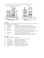
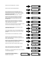
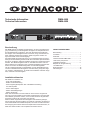
Frontseite
MIC
INPUT
LINE
PHONES
DMM 4650 DIGITAL MESSAGE MANAGER
EXIT
1
2
3
4
5
7
6
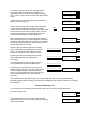
1. INPUT MIC
XLR-Buchse zum Anschluß eines Mikrofons umeine Message aufzunehmen. Über diesen Eingang kann auch eine
Durchsageerfolgen (Announcement).
8
POWER
9
6. CURSOR
CURSOR-Tasten, um den Cursor im Display zusteuern
und Daten zu verändern.
7. RECORDER
Tasten für.TITEL-Sprung rückwärts, RÜCKLAUF, PLAYSTOP, AUFNAHME, VORLAUF, TITEL-Sprung vorwärts.
2. INPUT LINE
Cinch-Buchsen zum Anschluß von Stereo- oder Monoquellen (Tape, CD-Player), um eine Message aufzunehmen.
8. EXIT
Taste für schnelles Beenden des jeweils eingestellten
Modus. Jeder Tastendruck schaltet eine Menüstufe zurück.
3. PHONES
Stereoklinke 6,3 mm zum Vorhören von Message, Gongund Alarm-Signalen über Kopfhörer.
9. POWER
LED leuchtet wenn das DMM 4650 betriebsbereit ist.
BLINKT wenn Service erforderlich ist.
4. MULTIFUNKTIONS-DISPLAY
LCD-Display 2 Zeilen a 16-stellig, Hintergrund-beleuchtung. LCD-Beleuchtung ein durch Drücken einer beliebigen Taste.LCD-Beleuchtung aus, wenn 5 Min. keine
Taste gedrückt wurde oder drücken der EXIT-Taste.
5. SOFTKEY
Die SOFTKEY-Tasten werden in Abhängigkeit vom Editiermodus unterschiedlich verwendet und entsprechend
im Display angezeigt.
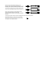
Rückseite
DMM 4650
24V
+
-
5
1
REMOTE
10
11
14
MADE IN GERMANY
121675
1
6
9
SER.NO.
13
POR T A
12
25
1
14
13
POR T B
25
1
14
13
13
POR T C
14*
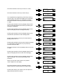
10. 24 V= Stromversorgung
2 Flachstecker 6,3 mm für die Versorgungsspannung aus
Notstrombatterien oder externen Netzteilen. Auf richtige
Polarität (+-) muß geachtet werden.
25
1
14
13
POR T D
15*
25
PRE-OUT
16
REC-INP
17
OUTPUT
18
INPUT
19
16. PRE-OUT
Cinch-Buchse, Vorhören (parallel zur Stereo-klinke 6,3
mm auf der Frontblende).
17. REC-INP
Cinch-Buchse, Aufnahme, (parallel, entkoppeltzur CinchBuchse Input Line auf der Frontblende).
11. REMOTE
Die 9 pol. SUB-D Buchse Remote Control RS 232 ist eine
serielle Computerschnittstelle (z. B. PC), um Datensicherung und Servicefunktionen auszuführen.
18. OUTPUT
XLR-Stecker 3pol. Audio-Output elektronisch symmetrisch (erdfrei symmetrisch nachrüstbar).
12 - 15. PORT A-D
Jeder Eingang und Ausgang ist 2polig aufgebaut und galvanisch vom DMM 4650 und Nachbarleitungen getrennt.
Port C (14) und Port D (15) sind nachrüstbar
(NRS 90024)
19. INPUT
XLR-Buchse 3pol. Audio-Input elektronisch symmetrisch
(erdfrei symmetrisch nachrüstbar).
3
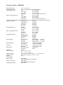
Technische Daten DMM 4650
Betriebsspannung
Leistungsaufnahme
Eingangsspannung
21, 6 - 31, 2 V DC
max. 18 Watt (ohne Nachrüstsätze 90204)
Input
0,775 V/0 dBu
*Line Input
0,775 V/0 dBu
*Rec Input
0,775 V/0 dBu
*Mic Input
1,4 mV/ -54 dBu an 600 Ohm
Max. Eingangsspannung
Input
3,8 V/+14 dBu
*Line Input
30 V/+32 dBu
*Rec Input
30 V/+32 dBu
*Mic Input
50 mV/ -24 dBu an 600 Ohm
* Werden mehrere dieser Eingänge gleichzeitig benutzt, ändern sich die angegebene Spannung
Eingangsimpedanz
Input (sym.)
20 kOhm
Input (unsym.)
10 kOhm
Line Input
20 kOhm
Rec Input
20 kOhm
Mic Input
1,4 kOhm
Ausgangsspannung
Output
0,775 V/0 dBu
Pre-Output
3,2 V/+12 dBu
Phones
3,2 V/+12 dBu
Max. Ausgangsspannung
Output
3,8 V/+14 dBu
Pre-Output
9 V/+21 dBu
Phones
9 V/+21 dBu
Ausgangsimpedanz
Output (sym.)
136 Ohm
Output (unsym.)
68 Ohm
Pre-Output
220 Ohm
Phones
220 Ohm
Frequenzgang
Input > Output
20 Hz-20 kHz -3 / 0 dB
Mic-Input
20 Hz-16 kHz -18 / -3 dB
Sonstige
20 Hz-16 kHz +0 / -3 dB
Rauschabstand
Input > Output
>108 dB (A-bewertet)
Message
> 90 dB (A-bewertet)
Klirrfaktor
Input > Output
< 0,03 % (bei 1 kHz)
Message
< 0,05 % (bei 1 kHz)
Datenformat
AD / DA Wandler
16 Bit linear
DSP intern
24 Bit
Abtastrate
35 kHz
Steuereingänge
Uin < ± 5 V = Low
Uin > ± 10 V = High
Steuerausgänge
Potentialfreie Relaiskontakte
1 A bei 24 V DC
Abmessungen
483 x 43,6 x 225 (B x H x T). 19”, 1 HE
Gewicht
4 kg
Nachrüstsätze
Port C oder D
NRS 90204
4 Steuereingänge und -ausgänge
Memory Extension
NRS 90205
Messagespeicher-Erweiterung
Ausgangsübertrager
NRS 90210
4
Liste Factory Sequenzen
Sequenz
Titel
Beschreibung
Priorität
Stoppbedingung
S 20
“Stop all”
Stoppt alle laufenden Sequenzen
99
off
S 21
“Alarmtxt”
Start Alarm (Message 00) einmal
97
off
S 22
“DIN-ALrm”
Start DIN Alarm endlos
(Heulton 1200Hz - 500Hz je 1sec)
93
off
S 23
“DIN-ALrm”
Start DIN-Alarm (Taste B1 ein), Stop mit
Taste B1 aus
95
B1 Low >00,1s stc
S 24
“Alrm-Txt”
DIN-Alarm > Alarm-Text > DIN-Alarm
Folge, (Start Taste B2 ein), Stop mit Taste
B2 aus
91
B2 Low >00,1s stc
S 25
“Vierklng”
Vierklang-Gong
89
off
S 26
“Vorgong”
Start Vorgong (Taste B4 ein), Ende der
Durchsage mit Taste B4 aus
87
B4 Low >00,1s stc
S 27
“Message1“
Starte Message 1
80
off
S 28
“Message2“
Starte Message 2
80
off
S 29
“EasyRec1“
Starte Aufnahme Message 01
(Fernrecording),Start durch kurzen Druck
auf Input C3 (Menü Auslöser-Trigger),
Stop durch nochmaligen Druck auf Input
C3
80
C3 High >00,1s lat
S 30
“EasyRec2“
Starte Aufnahme Message 02
(Fernrecording),Start durch kurzen Druck
auf Input C4 (Menü Auslöser-Trigger),
Stop durch nochmaligen Druck auf Input
C4
80
C4 High >00,1s lat
S 31
“Fire-Mic”
Start DIN-Alarm endlos, Drücken der Taste Feuermikrofon erlaubt Durchsage über
Audio Input, Taste loslassen und Alarm
läuft weiter
98
off
S 32
“Ansage”
Durchsage über Aufnahme Input DMM
4650 solange Taste gedrückt bleibt (Anlagen Input-20dB).
80
D3 Low >00,1s stc
S 33
“BZB-ABC”
BZB-ABC Alarm
95
off
S 34
“gen-emgc”
Schiffs-Alarm “general Emergency”
95
off
S 35
5“fireship”
Schiffs-Alarm “Feuer”
95
off
S 36
“ManMorse”
Schiffs-Alarm “Manuelle Morse Taste”
95
off
S 37
“Telefon”
Telefon Klingel
95
off
5
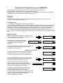
Für die Anwendung von Herstellereinstellungen (Presets) folgendes Installations Beispiel:
EINGÄNGE:
Alle Eingangssignale müssen länger als 200 ms anliegen um sicher erkannt zu werden. Diese Vorgabe
kann im Menü “Auslöser” verändert werden.
A1
Freigabe Signal:
Eingang für Rückmeldung ob Anlage (Endstufen) bereit.
A2
General Stop:
Eingang (Puls) für Unterbrechung aller gerade aktiven Sequenzen.
A3
Alarm Text:
Eingang (Puls) für vorher aufgesprochene Alarm Message (M00).
A4
DIN Alarm:
Eingang (Puls) für DIN-Alarm endlos (Heulton 1200 Hz - 500 Hz).
B1
DIN Alarm:
Taste gedrückt für DIN-Alarm ein, Taste öffnen beendet Alarm.
B2
DIN Alarm Text:
Taste gedrückt startet die Folge, DIN Alarm, 1sec Pause, Alarmtext (M00)
1sec Pause, DIN Alarm usw., Taste öffnen beendet diese Folge.
B3
Vierklang Gong:
Eingang (Puls) für Start Vierklang Gong (G20).
B4
Vorgong:
Eingang (statisch), Taste gedrückt startet Vorgong und gibt Durchsage
über DMM 4650 Input frei, Taste öffnen beendet diesen Ablauf.
AUSGÄNGE:
Alle Ausgänge sind potentialfreie Relaiskontakte.
A1
Anlage ein:
Schaltet eine Ela-Anlage in den aktiven Zustand.
A2
Alarm Text läuft:
Meldekontakt für Alarmtext aktiv.
A3
Alarm Signal läuft:
Meldekontakt für Alarmsignal aktiv.
A4
Vierklang Gong läuft: Meldekontakt für Vierklang Gong aktiv.
B1
Vorgong läuft:
Meldekontakt für Vorgong aktiv.
B2
Pflichtempfang Rel. E: Schaltet Ela-Anlage auf Pflichtempfang (E).
B3
Pflichtempfang Rel. D: Schaltet Ela-Anlage auf Pflichtempfang (D).
B4
Programm Aus:
Schaltet laufendes Musikprogramm aus.
6
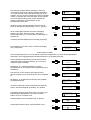
Beispiele für Programmierung von DMM 4650
Die Seitenhinweise (Sxxx) beziehen sich auf das Benutzerhandbuch DMM 4650.
Die angegebenen Beispiele basieren auf folgendem Gerätestatus:
Software Version 1.1 (Seite 22), Gerät befindet sich im Auslieferungszustand (Seite 27 und Seite 36),
die Bedienung wird unter Userlevel 3 vorgenommen (Seite 10).
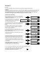
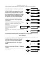
Beispiel 1
Zielvorgabe:
Aufnahme einer wichtigen Textdurchsage (Message), deren Wiedergabe durch Drücken einer
externen Taste gestartet werden kann.
Bedienübersicht:
1. Aufnahme einer Message (z.B. M03) in Sprachqualität.
2. Um die Wiedergabe dieser Message in die vorhandene Installation einzubinden, wird eine geeignete
Steuersequenz (z.B. S03) erstellt, die mit einer Priorität (Vorrang) zwischen Feueralarmierung und
Gong (z.B. Priorität 90) versehen wird. Diese Sequenz schaltet auch für die Dauer der Message eine
Meldelampe ein. Dazu wird in diesem Beispiel der Relaiskontakt 2 von Port A verwendet (=A2).
3. Ein unbenutzter Eingang (z.B. B.4) wurde mit der Starttaste verdrahtet (Seite 30) und muß nun im
Menü „Auslöser“ so programmiert werden, daß obige Sequenz (S03) mit dieser Taste gestartet werden
kann.
Bedienschritte:
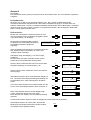
Mit den vier Cursortasten wird das Passwort für Userlevel 3 (Passwort= 3333) am Display eingegeben (Seite
10) und mit Softkey „ok“ bestätigt.
Bei korrekter Passworteingabe erscheint
am Display kurz nebenstehende Meldung.
Anschließend wird das Hauptmenü
angezeigt.
Ù
Ø
×
Durch Drücken der Aufnahmetaste zeigt das
Display einen Vorschlag für die Audioqualität der
neuen Aufnahme (Seite 14). Mit Softkey „ok“ wird
dieser Vorschlag bestätigt (Sprachqualität).
Hauptmenü
Einstellung
ok
Hauptmenü
Message
ok
Ù
Ø
×
Ú
2x
Aufnahme einer Message
Das Display zeigt Message 00 mit Namen ‘Message ’.
Die Zahl mm=Minuten und ss.s=Sekunden gibt die
Laufzeit einer eventuell vorhandenen Message 00 an.
M00’Message ‘ vl
mm:ss.s
edt
3x Ù
Durch 3-maliges Drücken dieser Cursortaste wird zur
gewünschten Message 03 geschaltet. Im Display wird
der Name der leeren Message 03 angezeigt.
ok
Ú
Dynacord DMM4650
Zugriffsrecht 3
Nach zweimaligen Drücken dieser Cursortaste erscheint
das „Message“ Menü. Mit Softkey „ok“ wird in das
„Message“ Menü verzweigt.
Passwort?
****
Ø
×
M03’
-leer
‘ vl
edt
Ú
Aufnahme-Art
8kHz long
I<< << >¨ O >> >>I
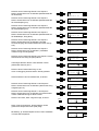
Am Display erscheint die Frage nach dem Aussteuerungspegel (Seite 14).Da dies unsere erste
Aufnahme mit diesem Mikrofon ist, muß der
Aussteuerpegel neu ermittelt werden. Das Mikrofon wird
an Buchse „MIC“ der Frontplatte angeschlossen und mit
Softkey „ja“ die automatische Einstellung des
elektronischen Reglers gestartet.
ok
Aufnahmepegel
neu wählen?
j
n
Es wird ein kurzer Sprachtest im gewünschten Mikrofonabstand und der richtigen Lautstärke vorgenommen.
Schaltet die Anzeige von „<min“ auf „norm“ um, so ist
der Pegel der Signalquelle im zulässigen Bereich.
Aufnahmepegel
test <min!
ok
Aufnahmepegel
test
norm
ok
Mit Softkey „ok“ wird diese Einstellung gespeichert und
bleibt erhalten (Seite 14).
Wurde durch einen zu hohen Eingangspegel die Anzeige
„>max“ erreicht, ist durch einmaliges Drücken der Taste
„EXIT“ ein Neubeginn ab Taste „Aufnahme“ erforderlich.
Der Sprechabstand zum Mikro muß vergrößert werden
(Eingangspegel kleiner).
Aufnahmepegel
test
norm
ok
EXIT
War der Pegel richtig („norm“ im Display), so zeigt das
Display nach Drücken der Taste Aufnahmepegel „ok“ die
Aufnahmebereitschaft. Der Bargraph in der unteren Zeile
ermöglicht eine Kontrolle des Eingangspegels. Der
Recorder befindet sich in Stellung „Pause“
(Aufnahmebereitschaft).
Durch Drücken der Taste Record wird die Aufnahme gestartet. Die Aufnahmezeit in m=Minuten
und ss,s=Sekunden wird angezeigt und am
Bargraphen kann der Eingangspegel kontinuierlich
überwacht werden.
Mit der Stoptaste wird die Aufnahme beendet,
wonach das Display den Ausgangsstatus
(Startmenü „Message“) anzeigt.
Durch Drücken der Taste Start/Stop kann am
Ausgang PHONES die Message abgehört werden.
Ist die Aufnahme nicht gelungen, so wird ein
neuer Versuch mit Taste „Record“ gestartet. In
diesem Fall erscheint nach dem Drücken der
Taste Record zuerst die Frage „löschen?“, was mit
Softkey „ja“ ausgeführt wird.
Aufnahmepegel
test
>max
ok
record M03
vl
Pause I========
I<< << >¨ O >> >>I
record M03
vl
m:ss,s I========
I<< << >¨ O >> >>I
M03’Message ‘ vl
mm:ss.s
edt
I<< << >¨ O >> >>I
I<< << >¨ O >> >>I
M03’Message ‘
löschen?
j
n
Die Message 03 ist nun gelöscht und eine neue Aufnahme (Taste RECORD) kann beginnen. Audioqualität und Aufnahmepegel müssen nur dann neu eingestellt werden, falls dies ein Grund für die
mangelhafte Aufnahme gewesen wäre.
Message Name, Titel
Um der neuen Message noch einen eigenen Namen zu geben, ist folgender Ablauf notwendig.
Drücken der Softkey „edit“.
Im Display erscheint das Untermenü „Message edit“. Mit
Softkey „ok“ wird zur Titeleingabe geschaltet.
M03’Message ‘ vl
mm:ss.s
edt
Message edit
Titel
ok
Der maximal 8 stellige Name (‘Message.’) kann nun
nach eigenen Wünschen geändert werden. Mit Softkey
„A-a“ wird zwischen Groß- und Kleinschreibung umgeschaltet, mit „spc“ können Leerzeichen (space) eingefügt
werden. Verändert wird immer die Stelle, an der gerade
der Cursor (blinkendes Zeichen) steht. Mit Hilfe der
beiden Cursortasten wird das Blinken an die
Nachbarstelle verschoben.
Mit diesen Tasten wird das Gewünschte Zeichen gewählt. Im Beispiel wird die Message ‘.Test.1.’ genannt.
Ù
Ø
×
Ú
Ù
Ø
×
Messg Titel
‘Message ‘
A-a
spc
Messg Titel
‘ essage ‘
A-a
spc
Messg Titel
‘ Test 1 ‘
A-a
spc
Ú
Ist die Titeleingabe beendet wird durch einmaliges
Drücken der Taste „EXIT“ die Frage „speichern?“
gestellt. Mit Softkey „ja“ wird der Name für Message 03
gespeichert.
M03’ Test 1 ‘
speichern?
EXIT
Im Display wird das Startmenü für Message angezeigt.
j
n
M03’ Test 1 ‘ vl
mm:ss.s
edt
Einmal Drücken der Taste „EXIT“ schaltet das Display
zum „Hauptmenü“.
EXIT
Hauptmenü
Message
ok
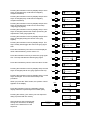
Steuersequenz erstellen
Die neue Message wird nun in eine Sequenz (Seite 23) eingebunden, um deren Wiedergabeablauf
festzulegen. Als Ausgangsbeispiel wird Sequenzpreset S 27 gewählt (Seite 39).
Nach dreimaligem Drücken der Cursortaste erscheint
nebenstehende Anzeige. Mit Softkey „ok“ wird in das
„Sequenz“ Menü verzweigt.
Ù
Ø
×
Ú
3x
Mit Softkey „ok“ schaltet das Display zu einem
Auswahlmenü um eine gewünschte Vorgabesequenz zu
selektieren.
Das Zeichen 0 in der unteren Zeile blinkt (Cursor).
Die Cursortaste wird so oft gedrückt bis „S27“ eingestellt
ist.
Hauptmenü
Sequenz
ok
Sequenz
laden
ok
Ù
Ø
×
Sequ laden
j
S20 ‘stop all’ n
Ú
Mit Softkey „ja“ wird das Preset Sequenz S27 geladen
(Ausgangssequenz).
Sequ laden
j
S27 ‘Message1’ n
Da wir den Ablauf für unsere Anforderungen abändern
wollen, wird die Schrittliste mit Softkey „ok“ gewählt.
Sequenz
Schrittliste
Das Display zeigt die erste Stufe (step 1) aus S27. Den
Relaisausgang (Meldelampe), hier Port C Relais 1,
ändern wir in Port A Relais 2 ab.
Schrittliste
1:OutC.1 set
l
e
Ø
Schrittliste
1:OutC.1 set
l
e
Ø
Schrittliste
1:OutA.1 set
l
e
Ù
Zweimal Drücken der Cursortaste läßt „C“ blinken.
×
Ú
2x
2x Ù
Zweimaliges Drücken dieser Taste selektiert Port A
×
Ú
ok
Ù
Drücken der Cursortaste läßt „1“ blinken.
×
Ø
Schrittliste
1:OutA.1 set
l
e
Ø
Schrittliste
1:OutA.2 set
l
e
Ø
Schrittliste
1:OutA.2 set
l
e
Ø
Schrittliste
2:Sum=off
l
e
Ø
Schrittliste
3:DMM= -2dB
l
e
Ø
Schrittliste
4:Start M01
l
e
Ø
Schrittliste
4:Start M01
l
e
Ø
Schrittliste
4:Start M03
l
e
Ø
Schrittliste
4:Start M03
l
e
Ø
Schrittliste
5:wt Audio
l
e
Ø
Schrittliste
6:End
l
e
Sequ sichern
in S27
j
n
Sequ sichern
in S03
j
n
Sequ sichern
in S03
j
n
Sequenz
Schrittliste
ok
Ú
Ù
Drücken dieser Taste selektiert Relais 2
×
Ú
Die Programmierung für das Schließen (set) von
Relaiskontakt 2 des Port A ist abgeschlossen. Damit
wird bei Start unserer Sequenz eine extern installierte
Meldelampe eingeschaltet.
Dreimal Drücken der Cursortaste läßt „1“ blinken.
Drücken dieser Taste zeigt Schritt 2 der Sequenz.
Diesen Schritt lassen wir unverändert. (Schaltet
Summeneingang des Gerätes während unserer
Message aus).
Drücken dieser Taste zeigt Schritt 3 der Sequenz.
Diesen Schritt lassen wir unverändert. (Lautstärke
unserer Message wird eingestellt).
Drücken dieser Taste zeigt Schritt 4 der Sequenz. Dieser
Schritt würde die Message eins (M01) starten.
Ù
×
Ú
3x
Ù
×
Ú
Ù
×
Ú
Ù
×
Ú
Viermaliges Drücken dieser Taste stellt den Cursor
(blinkendes Zeichen) auf 1.
Ù
×
Ú
Zweimaliges Drücken dieser Taste wählt Message 03
aus. Unsere Aufnahme (M03) wird mit diesem Schritt
gestartet.
4x
2x Ù
×
Ú
Ù
Zweimal Drücken der Cursortaste läßt „4“ blinken.
×
Ú
Drücken dieser Taste zeigt Schritt 5 der Sequenz.
Diesen Schritt lassen wir unverändert. (Warten bis zum
Ende unserer Message).
Drücken dieser Taste zeigt Schritt 6 der Sequenz.
Diesen Schritt lassen wir unverändert. Der letzte Schritt
unserer Ablaufsteuerung ist damit erreicht.
Ù
×
Ú
Ù
×
Ú
Drücken der Taste „EXIT“ zeigt die Frage „sichern?“
Diese Taste sooft drücken, bis das Display unsere
gewünschte Sequenznummer (S03) zeigt.
2x
EXIT
Ù
Ø
×
Ú
Mit Softkey „ja“ wird das Speichern der neuen Schrittliste
in Preset S03 ausgeführt
Das erfolgreiche Sichern wird kurz
bestätigt und das Display schaltet zum
Startmenü der Sequenz.
Sequenz
gespeichert
Sequenz Name, Titel
Soll der neuen Sequenz noch ein eigener Name gegeben werden, ist folgender Ablauf notwendig.
Drücken dieser Cursortaste schaltet zum Titelmenü.
Mit Softkey „ok“ wird zur Titeleingabe geschaltet.
Ù
Ø
×
Sequenz
Titel
ok
Ú
Die weiteren Bedienschritte für Eingabe und Sichern des gewünschten Namens entsprechen den
Tastendrücken, wie bereits im Menü „Message - Titel“ ändern beschrieben wurde. (Seite 24)
Sequenz Priorität, Vorrang
Um der neuen Sequenz in unserer installierten Anlage den gewünschten Rang zu verschaffen, wird die
Priorität der Sequenz S03 auf 90 eingestellt.
Dreimaliges Drücken dieser Cursortaste schaltet zum
Prioritätsmenü.
Mit Softkey „ok“ wird zur Prioritätseingabe geschaltet.
Ù
Ø
×
Ú
3x
Das Display zeigt die Priorität der Ausgangssequenz S27
an.
Diese Taste wird sooft gedrückt bis unsere Wunschpriorität 90 erreicht ist.
Sequenz
Priorität
ok
Sequ Priorität
80
Ù
Ø
×
Sequ Priorität
90
Ú
Durch Drücken der Taste „EXIT“ wird die Frage
„speichern?“ gestellt.
Mit Softkey „ja“ wird die Priorität für Sequenz 03
gespeichert.
Das erfolgreiche Sichern wird kurz
bestätigt und das Display schaltet zum
Prioritätsmenü der Sequenz.
Sequ sichern
in S03
EXIT
Sequenz
gespeichert
Einmal Drücken der Taste „EXIT“ schaltet das Display
zum „Hauptmenü“.
Das Erstellen unserer gewünschten Ablaufsteuerung ist
damit abgeschlossen.
EXIT
j
n
Sequenz
Priorität
ok
Hauptmenü
Sequenz
ok
Auslöser, Trigger erstellen
Die neue Sequenz soll mit der gewünschten Taste an Port B Eingang 4 gestartet werden können.
Dafür wird im Menü „Auslöser“ die Programmierung vorgenommen.
Drücken dieser Cursortaste schaltet zum Auslösermenü.
Mit Softkey „ok“ wird in das „Auslöser“ Menü verzweigt.
Ù
Ø
×
Hauptmenu
Auslöser
ok
Ú
Das Display zeigt, daß Eingang 1 von Port A abgeschaltet ist.
Drücken dieser Taste stellt auf Port B. Die untere Zeile
zeigt die Einstellung von Port B Eingang 1 an.
Auslöser A.1 set
off
Ù
×
Ø
Auslöser B.1 set
H >00,1s dyn S23
Ø
Auslöser B.1 set
H >00,1s dyn S23
Ú
Drücken dieser Taste schaltet den Cursor zur Nummer
des Eingangs.
Ù
×
Ú
Drücken dieser Taste wählt den Eingang 4 aus .
Die untere Zeile zeigt die bisherige Einstellung von Port
B Eingang 4 an, welche die Sequenz 26 starten würde.
Um unsere neue Sequenz 03 zu starten stellen wir den
Cursor durch zweimaliges Drücken dieser Taste auf „6“.
Ù
×
Ø
Auslöser B.4 set
H >00,1s dyn S26
Ø
Auslöser B.4 set
H >00,1s dyn S26
Ø
Auslöser B.4 set
H >00,1s dyn S03
Ú
2x Ù
×
Ú
Diese Taste sooft drücken, bis das Display unsere
gewünschte Sequenznummer (S03) zeigt.
Durch Drücken der Softkey „set“ wird diese Einstellung
gesichert.
Ù
×
Ú
In Zukunft wird mit der externen Taste am Eingang B4 unsere Sequenz 03 gestartet.
Zweimaliges Drücken der Taste „EXIT“ beendet die
Bedienung. Das Display wird dunkel und die Funktion
von Beispiel 1 kann getestet werden.
EXIT
2x
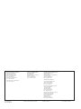
Beispiel 2
Zielvorgabe:
Ein vorhandener Alarm (Factory Preset) wird durch eine andere Taste, als vom Hersteller vorgesehen,
ausgelöst.
Bedienübersicht:
Mit einem von mir bisher nicht genutzten Eingang (z.B. B.3), soll der im DMM 4650 bereits
vorhandene DIN-Alarm ausgelöst werden. Der schon verwendete Eingang A4 für DIN-Alarm soll
weiterhin funktionieren. Die neue, zusätzliche Starttaste wurde bereits mit Port B Eingang 3 verdrahtet
(Seite 30) und muß nun im Menü „Auslöser“ so programmiert werden, daß die Sequenz „Ablauf DINAlarm“ (=S22) gestartet werden kann.
Bedienschritte:
Mit den vier Cursortasten wird das Passwort für Userlevel 3 (Passwort= 3333) am Display eingegeben (Seite
10) und mit Softkey „ok“ bestätigt.
Bei korrekter Passworteingabe erscheint
am Display kurz nebenstehende Meldung.
Anschließend wird das Hauptmenü
angezeigt.
Ù
Ø
×
2x Ù
Ø
×
ok
Hauptmenü
Auslöser
ok
Auslöser A.1 set
off
Ù
Ø
×
Ú
Drücken dieser Taste schaltet den Cursor zur Nummer
des Eingangs.
Hauptmenü
Einstellung
Ú
Das Display zeigt, daß Eingang 1 von Port A abgeschaltet ist.
Es kann immer die Stelle verändert werden, an der
gerade der Cursor (blinkendes Zeichen) steht.
Drücken dieser Taste stellt auf Port B. Die untere Zeile
zeigt die Einstellung von Port B Eingang 1 an.
ok
Ú
Dynacord DMM4650
Zugriffsrecht 3
Nach zweimaligen Drücken dieser Cursortaste erscheint
das „Auslöser“ Menü. Mit Softkey „ok“ wird in das
„Auslöser“ Menü verzweigt.
Passwort?
****
Auslöser B.1
set
H >00,1s dyn S23
Ù
×
Ø
Auslöser B.1 set
H >00,1s dyn S23
Ø
Auslöser B.3 set
H >00,1s dyn S25
Ø
Auslöser B.3 set
H >00,1s dyn S25
Ø
Auslöser B.3 set
H >00,1s dyn S22
Ú
Zweimaliges Drücken dieser Taste wählt den Eingang 3
aus . Die untere Zeile zeigt die bisherige Einstellung von
Port B Eingang 3 an, welche die Sequenz 25 starten
würde.
Um unsere Alarm-Sequenz 22 zu starten stellen wir den
Cursor durch zweimaliges Drücken dieser Taste auf „5“.
2x Ù
×
Ú
2x Ù
×
Ú
Diese Taste dreimal drücken und das Display zeigt
unsere gewünschte Sequenznummer (S22).
Durch Drücken der Softkey „set“ wird diese Einstellung
gesichert.
Ù
×
Ú
3x
In Zukunft wird mit der externen Taste am Eingang B3 unsere Sequenz 22 gestartet.
Zweimaliges Drücken der Taste „EXIT“ beendet die
Bedienung. Das Display wird dunkel und die Funktion
von Beispiel 2 kann getestet werden.
EXIT
2x
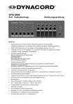
Beispiel 3
Zielvorgabe:
Der vorhandene 3-Klanggong (Factory Preset G21) soll durch eine externe Taste gestartet werden.
Der 4-Klanggong wird weiterhin benötigt.
Bedienübersicht:
1. Um die Wiedergabe des 3-Klanggongs (G21) in die vorhandene Installation einzubinden, wird eine
geeignete Steuersequenz (z.B. S05) erstellt. Diese Sequenz schaltet auch für die Dauer des Gong
eine Meldelampe ein. Dazu wird in diesem Beispiel derselbe Relaiskontakt 4 von Port A verwendet
(=A4), welcher bereits vom 4-Klanggong benutzt wird.
2. Der unbenutzter Eingang des Vorgong (z.B. B.4) wurde mit der Starttaste verdrahtet (Seite 30) und
muß nun im Menü „Auslöser“ so programmiert werden, daß obige Sequenz (S05) mit dieser Taste
gestartet werden kann.
Bedienschritte:
Mit den vier Cursortasten wird das Passwort für Userlevel 3 (Passwort= 3333) am Display eingegeben (Seite
10) und mit Softkey „ok“ bestätigt.
Bei korrekter Passworteingabe erscheint
am Display kurz nebenstehende Meldung.
Anschließend wird das Hauptmenü
angezeigt.
Ù
Ø
×
Passwort?
****
ok
Ú
Dynacord DMM4650
Zugriffsrecht 3
Hauptmenü
Einstellung
ok
Steuersequenz erstellen
Der 3-Klanggong G21 wird nun in eine Sequenz (Seite 23) eingebunden, um deren Ablauf festzulegen.
Als Ausgangsbeispiel wird Sequenzpreset S 25 gewählt (S39).
Nach fünfmaligen Drücken dieser Cursortaste erscheint
das „Sequenz“ Menü. Mit Softkey „ok“ wird in das
„Sequenz“ Menü verzweigt.
Ù
Ø
×
Ú
5x
Mit Softkey „ok“ schaltet das Display zu einem
Auswahlmenü um eine gewünschte Vorgabesequenz zu
selektieren.
Das Zeichen 0 in der unteren Zeile blinkt (Cursor).
Die Cursortaste wird so oft gedrückt bis „S25“ eingestellt
ist.
Mit Softkey „ja“ wird das Preset Sequenz S25 geladen
(Ausgangssequenz).
ok
Sequenz
laden
ok
Sequ laden
j
S20 ‘stop all’ n
5x Ù
×
Ø
Sequ laden
j
S25 ‘Vierklng’ n
Ú
Da wir den Ablauf für unsere Anforderungen abändern
wollen, wird die Schrittliste mit Softkey „ok“ gewählt.
Sequenz
Schrittliste
Das Display zeigt die erste Stufe (step 1) aus S25.
Diesen Schritt lassen wir unverändert (Relaiskontakt A1
kann für Anlage ein verwendet werden).
Drücken dieser Taste zeigt Schritt 2 der Sequenz.
Diesen Schritt lassen wir unverändert (Freigabeeingang
A1 für Elaanlage bereit?)
Hauptmenü
Sequenz
Ù
Ø
×
Ú
ok
Schrittliste
1:OutA.1 set
l
e
Schrittliste
2:wt InA.1 H
l
e
Drücken dieser Taste zeigt Schritt 3 der Sequenz.
Diesen Schritt lassen wir unverändert (Relaiskontakt B4
für Musik aus).
Ù
Ú
×
Drücken dieser Taste zeigt Schritt 5 der Sequenz.
Diesen Schritt lassen wir unverändert (Relaiskontakt B3
für Pflichtempfang ein).
×
Drücken dieser Taste zeigt Schritt 7 der Sequenz.
Diesen Schritt lassen wir unverändert. (Schaltet
Summeneingang des Gerätes während unserer Gongs
aus).
Drücken dieser Taste zeigt Schritt 8 der Sequenz.
Diesen Schritt lassen wir unverändert. (Lautstärke
unseres Gong wird eingestellt).
Drücken dieser Taste zeigt Schritt 9 der Sequenz. Dieser
Schritt würde den Gong 20 (G20) starten.
Schrittliste
l
3:OutB.4 clr
e
Ø
Schrittliste
4:OutB.2 set
l
e
Ø
Schrittliste
5:OutB.3 set
l
e
Ø
Schrittliste
6:OutA.4 set
l
e
Ø
Schrittliste
7:Sum=off
l
e
Ø
Schrittliste
8:DMM= -2dB
l
e
Ø
Schrittliste
9:Start G20
l
e
Ø
Schrittliste
9:Start G20
l
e
Ø
Schrittliste
9:Start G21
l
e
Ø
Schrittliste
9:Start G21
l
e
Ø
Schrittliste
10:wt Audio
l
e
Ø
Schrittliste
11:End
l
e
Sequ sichern
in S25
j
n
Sequ sichern
in S05
j
n
Sequ sichern
in S05
j
n
Ù
Drücken dieser Taste zeigt Schritt 4 der Sequenz.
Diesen Schritt lassen wir unverändert (Relaiskontakt B2
für Pflichtempfang ein).
Drücken dieser Taste zeigt Schritt 6 der Sequenz.
Diesen Schritt lassen wir unverändert (Relaiskontakt A4
für Meldelampe „Gong läuft“).
Ø
×
Ú
Ù
Ú
Ù
×
Ú
Ù
×
Ú
Ù
×
Ú
Ù
×
Ú
Viermaliges Drücken dieser Taste stellt den Cursor
(blinkendes Zeichen) auf 0.
Ù
×
Ú
Drücken dieser Taste wählt Gong 21 aus.
Unser 3-Klanggong wird mit diesem Schritt gestartet.
4x
Ù
×
Ú
Ù
Zweimal Drücken der Cursortaste läßt „9“ blinken.
×
Ú
Ù
Drücken dieser Taste zeigt Schritt 10 der Sequenz.
Diesen Schritt lassen wir unverändert. (Warten bis Gong
ausgeklungen ist).
×
Drücken dieser Taste zeigt Schritt 11 der Sequenz.
Diesen Schritt lassen wir unverändert. Der letzte Schritt
unserer Ablaufsteuerung ist damit erreicht.
×
Ú
Ù
Ú
Drücken der Taste „EXIT“ zeigt die Frage „sichern?“
Diese Taste sooft drücken, bis das Display unsere
gewünschte Sequenznummer (S05) zeigt.
2x
EXIT
Ù
Ø
×
Ú
Mit Softkey „ja“ wird das Speichern der neuen Schrittliste
in Preset S05 ausgeführt
Das erfolgreiche Sichern wird kurz
bestätigt und das Display schaltet zum
Startmenü der Sequenz.
Sequenz
gespeichert
Sequenz
Schrittliste
ok
Sequenz Name, Titel
Um der neuen Sequenz noch einen eigenen Namen zu geben, ist folgender Ablauf notwendig.
Drücken dieser Cursortaste schaltet zum Titelmenü.
Mit Softkey „ok“ wird zur Titeleingabe geschaltet.
Ù
×
Ø
Sequenz
Titel
ok
Ø
Sequ Titel
‘Vierklng’
A-a
spc
Sequ Titel
‘Drerklng’
A-a
spc
Sequ Titel
‘Dreiklng’
A-a
spc
Ú
Der maximal 8 stellige Name (‘Vierklng’) kann nun nach
eigenen Wünschen geändert werden. Mit Softkey „A-a“
wird zwischen Groß- und Kleinschreibung umgeschaltet,
mit „spc“ können Leerzeichen (space) eingefügt werden.
Verändert wird immer die Stelle, an der gerade der
Cursor (blinkendes Zeichen) steht. Mit Hilfe der beiden
Cursortasten wird das Blinken an die Nachbarstelle
verschoben.
Mit diesen Tasten wird das Gewünschte Zeichen gewählt. Im unserem Beispiel wird die Sequenz ‘Dreiklng’
genannt.
Ù
×
Ú
Ù
Ú
Ist die Titeleingabe beendet wird durch einmaliges
Drücken der Taste „EXIT“ die Frage „speichern?“
gestellt. Mit Softkey „ja“ wird der Name für Sequenz 05
gespeichert.
Das erfolgreiche Sichern wird kurz
bestätigt und das Display schaltet zum
Titelmenü der Sequenz.
Ø
×
Sequ sichern
in S05
EXIT
Sequenz
gespeichert
Einmal Drücken der Taste „EXIT“ schaltet das Display
zum „Hauptmenü“.
Sequenz
Titel
EXIT
Hauptmenü
Sequenz
j
n
ok
ok
Das Erstellen unserer gewünschten Ablaufsteuerung ist damit abgeschlossen. Der Vorrang (Priorität)
unserer Sequenz wurde nicht geändert und enspricht somit der von S25 (4-Klanggong).
Auslöser, Trigger erstellen
Die neue Sequenz soll mit der gewünschten Taste an Port B Eingang 4 gestartet werden können.
Dafür wird im Menü „Auslöser“ die Programmierung vorgenommen.
Drücken dieser Cursortaste schaltet zum Auslösermenü.
Mit Softkey „ok“ wird in das „Auslöser“ Menü verzweigt.
Ù
Ø
×
Hauptmenu
Auslöser
ok
Ú
Das Display zeigt, daß Eingang 1 von Port A abgeschaltet ist.
Drücken dieser Taste stellt auf Port B. Die untere Zeile
zeigt die Einstellung von Port B Eingang 1 an.
Auslöser A.1 set
off
Ù
×
Ø
Auslöser B.1 set
H >00,1s dyn S23
Ø
Auslöser B.1 set
H >00,1s dyn S23
Ú
Drücken dieser Taste schaltet den Cursor zur Nummer
des Eingangs.
Ù
×
Ú
Drücken dieser Taste wählt den Eingang 4 aus .
Die untere Zeile zeigt die bisherige Einstellung von Port
B Eingang 4 an, welche die Sequenz 26 starten würde.
Um unsere neue Sequenz 05 zu starten, stellen wir den
Cursor durch zweimaliges Drücken dieser Taste auf „6“.
Ù
×
Ø
Auslöser B.4 set
H >00,1s dyn S26
Ø
Auslöser B.4 set
H >00,1s dyn S26
Ø
Auslöser B.4 set
H >00,1s dyn S05
Ú
2x Ù
×
Ú
Diese Taste sooft drücken, bis das Display unsere
gewünschte Sequenznummer (S05) zeigt.
Durch Drücken der Softkey „set“ wird diese Einstellung
gesichert.
Ù
×
Ú
In Zukunft wird mit der externen Taste am Eingang B4 unsere Sequenz 05 (= 3-Klanggong) gestartet.
Zweimaliges Drücken der Taste „EXIT“ beendet die
Bedienung. Das Display wird dunkel und die Funktion
von Beispiel 3 kann getestet werden.
EXIT
2x
Technical Information
DMM 4650
Description
CONTENTS
The DMM 4650 is a signal processor, allowing an universal generation and
control of audio signals. The main application is for PA racks, but standalone applications are possible as well. The audio signals can consist of
alarm, gong, messages and also random combinations. These programs
were created by Dynacord and stored as presets.
The audio quality of the messages can be selected depending on memory
extension and different user requirements. With maximum memory extension, a total recording time of 16 minutes is possible. Password protection
is provided. The operation is easy, like cassette recorders or CD players.
A computer interface allows saving and loading of unit configurations and
message data.
In order to ensure function reliability, a self-test and a audio data verification is installed. The alarm takes place via an own output “Fault/Error”. The
device is maintenance-free because no battery or accumulator is installed.
Description....................................................
Front Panel...................................................
Rear Panel...................................................
Specifications DMM 4650............................
List Factory Sequeces.................................
Installation example.....................................
Programming Examples for the DMM 4650..
Block diagram..............................................
Dimensions..................................................
Installation instructions
The appliance must be protected against:
- drip or splashwater
- direct sun irradiation
- high ambient temperature or direct influence of heat sources
- high air humidity
- heavy dust deposits
- strong vibrations
If the unit is brought directly from a cold to a warm place, dampness can
precipitate on the inner parts. The unit may only be put into operation after
it has warmed up to the ambient temperature (approx. after one hour).
Should an object or liquid get into the case, disconnect the unit from
the current sources immediately and have the device checked by a
DYNACORD service center, before further use.
Do not use any sprays to clean the unit, as these can damage it, perhaps
causing it to ignite suddenly.
18
18
20
20
21
22
23
24
35
35
IMPORTANT SAFETY INSTRUCTIONS
The lightning flash with arrowhead symbol, within an equilateral
triangle is intended to alert the user to the presence of
uninsulated „dangerous voltage“ within the product’s enclosure
that may be of sufficient magnitude to constitute a risk of
electric shock to persons.
The exclamation point within an equilateral triangle is intended
to alert the user to the presence of important operating
and maintance (servicing) instructions in the literature
accompanying the appliance.
1.
2.
3.
4.
5.
6.
7.
8.
9.
10.
11.
12.
13.
14.
15.
16.
Read these instructions.
Keep these instructions.
Heed all warnings.
Follow all instructions.
Do not use this apparatus near water.
Clean only with a dry cloth.
Do not block any ventilation openings. Install in accordance with the manufactures instructions.
Do not install near any heat sources such as radiators, heat registers, stoves, or other apparatus
(including amplifiers) that produce heat.
Do not defeat the safety purpose of the polarized or grounding-type plug. A polarized plug has two blades with one
wider than the other. A grounding type plug has two blades and a third grounding prong. The wide blade or the third
prong are provided for your safety. If the provided plug does not fit into your outlet, consult an electrican for replacement
of the obsolete outlet.
Protect the power cord from being walked on or pinched particularly at plugs, convenience receptacles, and the point
where they exit from the apparatus.
Only use attachments/accessories specified by the manufacturer.
Unplug this apparatus during lightning storms or when unused for long periods of time.
Refer all servicing to qualified service personnel. Servicing is required when the apparatus has been damaged in any
way, such as power-supply cord or plug is damaged, liquid has been spilled or objects have fallen into the apparatus,
the apparatus has been exposed to rain or moisture, does not operate normally, or has been dropped.
Do not expose this equipment to dripping or splashing and ensure that no objects filled with liquids, such as vases,
are placed on the equipment.
To completely disconnect this equipment from the AC Mains, disconnect the power supply cord plug from the AC
receptacle.
The mains plug of the power supply cord shall remain readily operable.
IMPORTANT SERVICE INSTRUCTIONS
CAUTION:
1.
2.
3.
4.
5.
6.
7.
8.
These servicing instructions are for use by qualified personnel only. To reduce the risk of
electric shock, do not perform any servicing other than that ontained in the Operating
Instructions unless you are qualified to do so. Refer all servicing to qualified service personnel.
Security regulations as stated in the EN 60065 (VDE 0860 / IEC 65) and the CSA E65 - 94 have to be obeyed when
servicing the appliance.
Use of a mains separator transformer is mandatory during maintenance while the appliance is opened, needs to be
operated and is connected to the mains.
Switch off the power before retrofitting any extensions, changing the mains voltage or the output voltage.
The minimum distance between parts carrying mains voltage and any accessible metal piece (metal enclosure),
respectively between the mains poles has to be 3 mm and needs to be minded at all times. The minimum distance
between parts carrying mains voltage and any switches or breakers that are not connected to the mains (secondary
parts) has to be 6 mm and needs to be minded at all times.
Replacing special components that are marked in the circuit diagram using the security symbol (Note) is only
permissible when using original parts.
Altering the circuitry without prior consent or advice is not legitimate.
Any work security regulations that are applicable at the location where the appliance is being serviced have to be
strictly obeyed. This applies also to any regulations about the work place itself.
All instructions concerning the handling of MOS - circuits have to be observed.
NOTE:
SAFETY COMPONENT ( MUST BE REPLACED BY ORIGINAL PART )
WEEE Recycling/Disposal Instructions
The Wheelie Bin symbol found on the product or in the manual indicates that this product must
not be disposed of with other waste. It is in our category the manufacturer’s responsibility to
properly dispose of their waste electrical and electronic equipment (WEEE) at the end of its
life. Due to the differences in each EU country’s management of WEEE, please contact your
local distributor. We are committed to facilitate our own electronic-waste-management-system,
for the free of charge return of all EVI Audio GmbH products: Telex, Dynacord, Electro-Voice,
Midas Consoles, KlarkTeknik and RTS. Arrangements are made with the dealer where you
purchased the equipment from, for the returning of all unusable equipment at no cost, to the
factory in Straubing, for environmental protective disposal.
19
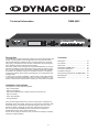
FRONTPANEL
MIC
INPUT
LINE
PHONES
DMM 4650 DIGITAL MESSAGE MANAGER
EXIT
1
2
3
4
5
7
6
8
POWER
9
6. CURSOR CURSOR
Keys to control the cursor in the display and for modifying
data.
1. INPUT MIC
XLR socket for connection of a microphone, to record
a message. Announcements can also be made via this
input.
7. RECORDER
Keys for TITLE jump back, REW, PLAY, STOP, REC,
FAST FORWARD, TITLE jump forward.
2. INPUT LINE
Cinch (RCA) socket for connection of stereo or mono
sources (tape deck, CD player) to record a message.
8. EXIT
Key for fast ending of the resp. mode. Each pressing of
the key switches back one menu stage.
3. PHONES
Stereo jack 6.3mm for pre-listen of messages, gong and
alarm signals via headphones.
9. POWER
The LED lights up if the DMM 4650 is ready for operation.
If the LED blinks please call a DYNACORD service center immediately.
4. MULTIFUNCTIONAL DISPLAY
Back-lit LC display, 2 lines with 16 characters each. Display lights up if any key is pressed. Display light switches
off if EXIT key is pressed, or no key is pressed for five
minutes.
5. SOFTKEY
The softkeys are used in various ways, depending on the
edit mode, and are indicated accordingly in the display.
REARPANEL
DMM 4650
24V
+
-
5
1
REMOTE
10
11
14
MADE IN GERMANY
121675
1
6
9
SER.NO.
13
POR T A
12
25
1
14
13
POR T B
25
1
14
13
13
POR T C
14*
10. 24 V DC POWER CONNECTORS
2 flat-pin plugs 6,3mm for connection to emergency power supply or external power sources. Please note right
polarity (+)!
25
1
14
13
POR T D
15*
25
PRE-OUT
16
REC-INP
17
OUTPUT
18
INPUT
19
16. PRE-OUT
Cinch (RCA) socket, pre-listen (wired in parallel to the
front-panel stereo jack).
17. REC-INP
Cinch (RCA) socket, record (parallel but decoupled to the
cinch socket Input Line at the front panel).
11. REMOTE
The 9-pole D-SUB connector REMOTE is a serial computer interface (RS-232) for data saving and for service
functions.
18. OUTPUT
XLR socket 3-pole male, audio output, electronically balanced (transformer can be retrofitted).
12 - 15. PORT A - D
Each input and output is provided in 2-pole floating design and isolated from the DMM 4650 circuit and adjacent
lines. Port C (14) and Port D (15) can be retrofitted (NRS
90024).
19. INPUT
XLR socket 3-pole female, audio input, electronically balanced (transformer can be retrofitted).
20
Specifications DMM 4650
Operating Voltage
Power consumption
21.6 - 31.2V DC
max. 18 watts (without retrofitting kits 90204)
Input voltage
Input
*Line Input
*Rec Input
*Mic Input
0.775V/0dBu
0.775V/0dBu
0.775V/0dBu
1.4mV/ -54dBu at 600 ohms
Max. Input voltage
Input
3.8V/+14dBu
*Line INPUT
30V/+32dBu
*Rec INPUT
30V/+32dBu
*Mic INPUT
50mV/ -24dBu at 600 ohms
* If several of these inputs are used simultaneously, the stated voltages change.
Input impedance
Input(bal.)
Input (unbal.)
Line Input
REC Input
Mic INPUT
20kOhm
10kOhm
20kOhm
20kOhm
1,4kOhm
Output voltage
Output
Pre-Output
Phones
0.775V/0dBu
3.2V/+12dBu
3.2V/+12dBu
Max. Output voltage
Output
3.8V/+14dBu
Pre-Output
9V/+21dBu
Phones
9V/+21dBu
Output (bal.)
136 Ohm
Output (unbal.)
68 Ohm
Pre-Output
220 Ohm
Phones
220 Ohm
Input > Output
20Hz-20kHz -3/0dB
Mic Input
20Hz-16kHz -18/3dB
Others
20Hz-16kHz +0/-3dB
Input > Output
> 108dB (A-weighted)
Message
> 90dB (A-weighted)
Input > Output
< 0.03% (at 1kHz)
Message
< 0.05% (at 1kHz)
AD/DA converter
16 bit linear
DSP internal
24 bit
35kHz
Ein < ± 5V = Low
Ein > ±10V = High
floating relay contacts 1A at 24V DC
483 X 43.6 X 225 (W x H x D) 19in, 1HU
4kg
Output impedance
Frequency response
Signal-to-noise ratio
THD
Data format
Sampling rate
Control inputs
Control outputs
Dimensions
Weight
Retrofitting kits
Port C or D
Memory extension
Output transformer
NRS 90204
4 control inputs and outputs
NRS 90205
message memory extension
NRS 90210
21
LIST FACTORY SEQUENCES
Sequence
Title
Description
Priority
Stopp trigger
S 20
“Stop all”
Stops all running sequences
99
off
S 21
“Alarmtxt”
Start alarm text (message 00) once
97
off
S 22
“DIN-ALrm”
Start continuous DIN alarm
(siren 1200 Hz - 500 Hz, 1 sec. Each)
93
off
S 23
“DIN-ALrm”
Start DIN alarm (key B1 ON), Stop with
key B1 OFF
95
B1 Low >00,1s stc
S 24
“Alrm-Txt”
DIN alarm > alarm text > DIN alarm
sequence, (start key B2 ON), Stop with
key B2 OFF
91
B2 Low >00,1s stc
S 25
“Vierklng”
4-tone gong
89
off
S 26
“Vorgong”
Start Pre-gong (key B4 on),
end of announcement with key B4 off
87
B4 Low >00,1s stc
S 27
“Message1“
Start Message 1
80
off
S 28
“Message2“
Start Message 2
80
off
S 29
“EasyRec1“
Start Recording Message 01
(remote recording), start by briefly pressing to input C3 (menu trigger), stop by
pressing again to input C3
80
C3 High >00,1s lat
S 30
“EasyRec2“
Start Recording Message 02
(remote recording), start by briefly pressing to input C4 (menu trigger), stop by
pressing again to input C4
80
C4 High >00,1s lat
S 31
“Fire-Mic”
Start continuous DIN alarm, pressing the
key “fire microphone” allows for an announcement via audio input, after releasing key the alarm is continued.
98
off
S 32
“Ansage”
Announcement via Recording input DMM
4650 as long as key is keeping pressed
(System input -20 dB).
80
D3 Low >00,1s stc
S 33
“BZB-ABC”
BZB-ABC alarm
95
off
S 34
“gen-emgc”
Ship alarm “General Emergency”
95
off
S 35
5“fireship”
Ship alarm “Fire”
95
off
S 36
“ManMorse”
Ship alarm “Manual Morse key”
95
off
S 37
“Telefon”
Telephone bell
95
off
22
Installation example with factory presets:
INPUTS:
All input signals must be applied 200 msec. in order to be recognised. This default can only be modified
in menu “Trigger”.
A1
A2
A3
A4
B1
B2
Release signal:
General Stop:
Alarm text:
DIN alarm:
DIN alarm:
DIN alarm text:
B3
B4
4-tone gong:
Pre-gong:
Input for check-back signal: unit (power amplifiers) ready
Input (impulse) for interruption of all currently running sequences
Input (impulse) for previously recorded alarm message (M00)
Input (impulse) for continuous DIN alarm (siren 1200 Hz - 500 Hz).
Key pressed for DIN alarm on, key released finishes alarm
Key pressed starts sequence, DIN alarm, 1 sec break, alarm text (M00),
1 sec break, DIN alarm, etc., key released finishes this sequence.
Input (impulse) for starting 4-tone gong (G20).
Input (static), key pressed starts pre-gong and enables announcement
via DMM 4650, key released finishes this sequence.
OUTPUTS:
All outputs are floating relay contacts.
A1
A2
A3
A4
B1
B2
B3
B4
System on:
Alarm text running:
Alarm signal running:
4-tone gong running:
Pre-gong running:
Mandatory relay E:
Mandatory relay D:
Program off:
Switches on PA system.
Signalling contact for alarm text active.
Signalling contact for alarm signal active.
Signalling contact for 4-tone gong active.
Signalling contact for pre-gong active.
Switches PA system to mandatory reception (E).
Switches PA system to mandatory reception (D).
Switches current music program off.
23
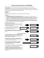
Programming Examples for the DMM 4650
Page numbers within brackets (Sxxx) refer to the corresponding page of the DMM 4650's
user's manual.
The following examples are based on the assumption that the appliance's mode is set as follows:
Software revision 1.1 (page 22), the DMM 4650 is in the factory-preset mode (page 27 and page 36),
operation is performed in the user level 3 status (page 10).
Example 1
Intention:
Recording a message that later on is to be played back using a external key.
Summary
1. Recording a message (i. e. M03) in speech quality.
2. To include the reproduction of this message in an existing installation, an appropriate control
sequence has to be established that gets a priority between "fire alert" and "gong" (i. e. priority 90).
This sequence also activates an optical signal in form of a lit lamp for the period of the outgoing
message. To accomplish the task, this example uses the relay contact 2 of the port A (=A2).
3. An input, which at the moment is unused (i. e. B.4) had been connected to the "Start"-key (page
30). This input has to be programmed in the "Auslöser" (trigger) menu for that pressing the start
button activates the above mentioned sequence (S03).
Step By Step Programming
Enter the password for the user level 3 on the display,
using the four cursor keys (page 10) and confirm your
action with the "ok"-button.
If you have entered the correct password,
the display briefly shows this message and
then returns to the main menu.
Ù
Ø
×
****
ok
Ú
Dynacord DMM4650
Userlevel 3
Main-Menu
System-Setup
Ù
After pressing this cursor key twice, the "Message"menu appears. Confirm your selection with the "ok"button.
Ø
×
Ú
2x
Recording a message
On the display the message number 00 and the name
"Message" is shown. The numeric values mm=minutes
and ss=seconds equal the time of a message that
already exists in the register 00.
ok
Main-Menu
Message
ok
M00’Message ‘ vl
mm:ss.s
edt
3x Ù
Pressing this cursor key three times displays the
required message register 03. The display shows the
name of the "empty" message 03.
Pressing the "record"-button displays a proposal
for the audio quality of the new recording (page
14). Using the soft key "ok" the proposition is
confirmed (speech quality).
password?
Ø
×
M03’
-empty
‘ vl
edt
Ú
I<< << >¨ O >> >>I
On the display you are asked for the level setting (page
14). Since this is your first recording with the
microphone, the level has to be set a new. The
microphone has to be connected to the MIC-socket on
the front panel and pressing the soft key "yes", the
automatic adjustment process for the electronic control
is activated.
record-mode
8kHz long
select new
recordlevel?
ok
y
n
You have to perform a short test, speaking into the
microphone with a normal talking level and in an
appropriate distance. Whenever the display changes
from "<min" to "norm" the mic level is within the relevant
range.
recordlevel
test
Using the soft key "ok" the setting is being stored and
stays in memory (page 14).
Pressing the button "start/stop" lets you control
your recording through the PHONES output.
If recording was not successful, you can give it
another try by pressing the "record" button. In this
case the display shows the message "delete?".
When you are sure that this is what you want, you
have to acknowledge the fact by pressing the
"yes" key.
recordlevel
test
norm
ok
test
EXIT
If the level was right ("norm" is shown on the display),
after pressing the "ok" key that the appliance is ready for
recording. The graphic bar in the lower line of the display
allows checking the input level. The Recorder is in the
pause-mode (ready to record).
Pressing the stop key terminates the recording
and the display shows the starting-menu
"message".
ok
recordlevel
In case the input level was too high and the indication
">max" has been displayed, you have to press the
"EXIT" button and follow the procedure once again from
the point where the record key was pressed. This time
the speaking distance to the microphone should be
increased; which results in a lower input level.
Pressing the record button starts the recording.
The recording time gets displayed in m=minutes
and ss, s= seconds and the graphic bar offers
continuous verification of the actual input level.
<min!
norm
ok
recordlevel
test
>max
ok
record M03
vl
paused I========
I<< << >¨ O >> >>I
record M03
vl
m:ss,s I========
I<< << >¨ O >> >>I
M03’Message ‘ vl
mm:ss.s
edt
I<< << >¨ O >> >>I
I<< << >¨ O >> >>I
M03’Message ‘
delete?
y
n
The message 03 is being erased and a you can proceed with a new recording (RECORD key).
Recording quality and level setting only have to be re-adjusted if they were the cause for re-recording
the message.
Naming The Message, Title
To provide the new recording (message) with a new name, you have to follow these steps:
Press the soft key "edit".
In the display appears the sub menu "Message edit".
Using the soft key "ok", the system is ready to accept the
entry of a new name.
M03’Message ‘ vl
mm:ss.s
edt
Message edit
title
ok
The name ("Message") with a maximum length of eight
characters can now be changed as desired. Using the
soft key "A-a" lets you choose between the upper and
the lower character set. By pressing the "spc" (space)
key you can enter spaces. The blinking cursor indicates
which character is going to be changed and using the
two "horizontal" cursor keys lets you select adjacent
characters.
The "vertical" cursor keys select the character that is
going to be entered at the cursor position. The example
shows the message 'Test 1.'.
Ù
Ø
×
Messg title
‘Message ‘
A-a
spc
Messg title
‘ essage ‘
A-a
spc
Messg title
‘ Test 1 ‘
A-a
spc
Ú
Ù
Ø
×
Ú
After you have entered the desired title, pressing the
"EXIT" key once displays the question "save?". Press the
soft key "yes" to store the selected name for the
Message 03 into memory.
M03’ Test 1 ‘
save?
EXIT
The display shows the starting menu for the message
programming.
y
n
M03’ Test 1 ‘ vl
mm:ss.s
edt
Pressing the "EXIT" button once lets you return to the
main menu.
EXIT
Main-Menu
Message
ok
Programming A Control Sequence
Creating a procedure, the newly defined message has to be included into a sequence (page 23). In this
example the sequence-preset S 27 is chosen as the root-preset for further programming (page 39).
Press the "right" cursor key three times so that the
display reads as indicated. Using the soft key "ok" gets
you into the "Sequence" menu.
Ù
Ø
×
Ú
3x
Pressing the soft key "ok" once again shows a menu that
lets you select a sequence-preset.
A blinking "0" (cursor) is displayed in the lower line.
Press the "up" cursor until the reading shows "S 27".
Main-Menu
Sequence
ok
Sequence
load
ok
Ù
Ø
×
Sequ load
y
S20 ‘stop all’ n
Ú
To acknowledge your selection press the "yes" key.
Sequ load
y
S27 ‘Message1’ n
Since the procedure has to be changed in accordance to
the new requirements, you have to select its listing by
pressing the "ok" key.
Sequence
steplist
The first step (step 1) of the S 27 listing is displayed.
Here, you have to change the relay output (indicator
lamp) from port C relay 1 to port A relays 2.
Press the indicated cursor key twice to have the "C"
blink.
steplist
1:OutC.1 set
d
i
Ø
steplist
1:OutC.1 set
d
i
Ø
steplist
1:OutA.1 set
d
i
Ù
×
Ú
2x
2x Ù
Press the indicated cursor key twice to select port A.
×
Ú
ok
Ù
Press the indicated cursor key to have the "1" blink.
×
Ø
steplist
1:OutA.1 set
d
i
Ø
steplist
1:OutA.2 set
d
i
Ø
steplist
1:OutA.2 set
d
i
Ø
steplist
2:Sum=off
d
i
Ø
steplist
3:DMM= -2dB
d
i
Ø
steplist
4:Start M01
d
i
Ø
steplist
4:Start M01
d
i
Ø
steplist
4:Start M03
d
i
Ø
steplist
4:Start M03
d
i
Ø
steplist
5:wt Audio
d
i
Ø
steplist
6:End
d
i
Sequ save
to S27
y
n
Sequ save
to S03
y
n
Sequ save
to S03
y
n
Ú
Ù
Press the indicated cursor key to select relay 2.
×
Ú
This completes the programming of the relay contact 2
of port A (set). The result is the lighting of an externally
connected lamp whenever your sequence is started.
Press the indicated cursor key three times to have the
"1" blink.
Pressing the indicated cursor key displays step 2 which
stays unchanged (disables the master input during the
message is outputted).
Pressing the indicated cursor key displays step 3 which
stays unchanged (sets the message's volume).
Ù
×
Ú
3x
Ù
×
Ú
Ù
×
Ú
Pressing the indicated cursor key displays step 4 which
activates the reproduction of the message "M01".
Ù
×
Ú
Pressing the indicated cursor key four times sets the
blinking cursor to the "1".
Ù
×
Ú
Pressing the indicated cursor key twice selects message
03. This starts the reproduction of your previously
recorded message "M03".
Press the indicated cursor key displays twice to have the
"4" blink.
2x Ù
×
Ú
Ù
×
Ú
Pressing the indicated cursor key displays step 5 which
stays unchanged (wait for the end of the message).
4x
2x
Ù
×
Ú
Pressing the indicated cursor key displays step 6 which
stays unchanged. This is also the last step of the
procedure.
Ù
×
Ú
When you press the "EXIT" button, the question
"save?" appears on the display.
Press the indicated cursor key repeatedly until the
display reads the required sequence number (S03).
EXIT
Ù
Ø
×
Ú
Pressing the soft key "yes" stores your new sequencelisting as preset S03 into memory.
After showing a short message that
storing was successful, the display
returns to the start-screen of the
sequence.
Sequence
Sequence
steplist
saved
ok
Naming The Sequence, Title
In case you want to give the new sequence its own name, you have to follow this procedure:
Pressing the indicated cursor key enters the title-menu.
Pressing the soft key "ok" prepares the system for the
entry of a new name.
Ù
Ø
×
Sequence
title
ok
Ú
The following programming steps – entering and saving the desired name - are equivalent to the above
description of how to enter and store the "title of a message" (page 24).
Priority Of The Sequence
The priority of the new sequence S03 has to be set to a value of 90. Thus, follow these steps:
The priority-menu is entered by pressing the indicated
cursor key three times and pressing the "ok" key
prepares the system for the entering of a new priority
value.
Ù
Ø
×
Ú
3x
The display shows the programmed priority of the
sequence S27.
Sequence
priority
ok
Sequ priority
80
Press the indicated cursor key until the required value of
"90" is displayed.
Ù
Ø
×
Sequ priority
90
Ú
Pressing the "EXIT" button displays the question
"save?". Use the soft key "yes" to save the priority
for the sequence S03.
After showing a short message that the
storing was successful, the display
returns to the priority-screen of the
sequence.
Sequ save
to S03
EXIT
Sequence
saved
Pressing the "EXIT" key once lets you return to the main
menu. This concludes the programming of your new
procedure.
Sequence
priority
y
n
ok
Main-Menu
EXIT
Sequence
ok
Setting The Trigger
You want your new sequence to be triggered by pressing the desired button on port B input 4. Thus,
the programming is performed in the "trigger" menu.
Pressing the indicated cursor key enters the trigger
menu. Press the "ok" button to acknowledge your
selection.
Ù
Ø
×
Trigger
ok
Ú
The display shows that the input 1 of the port A is
disabled.
Pressing the indicated cursor key selects the port B. In
the bottom line of the display, the setting for port B, input
1 is shown.
Main-Menu
starttrg A.1 set
off
Ù
Ø
×
Ú
starttrg B.1 set
H >00,1s dyn S23
Pressing the indicated key sets the cursor to the number
mark of the input.
Ù
×
Ø
starttrg B.1 set
H >00,1s dyn S23
Ø
starttrg B.4 set
H >00,1s dyn S26
Ø
starttrg B.4 set
H >00,1s dyn S26
Ø
starttrg B.4 set
H >00,1s dyn S03
Ú
Select the input 4 by pressing the indicated cursor key.
The bottom line of the display shows the momentary
setting for the port B, input 4, which would start the
sequence 26.
Programming the start of the sequence 03 you have to
press the indicated key twice to set the blinking cursor to
"6".
Press the indicated cursor key repeatedly until the
display shows the desired number of the sequence
(S03). Pressing the soft key "set" stores your setting into
memory.
Ù
×
Ú
2x Ù
×
Ú
Ù
×
Ú
From now on, pressing the external button at the input B4 activates the sequence 03.
Pressing the "EXIT" key twice ceases the programming.
The display is dimmed and you are able to test the
functioning of the sequence (example 1).
EXIT
2x
Example 2
Intention:
You want to activate a factory preset alert using another key than pre-programmed.
Summary
Employing a previously unused input (e. g. B3) you want to trigger included DIN-alert of the DMM 4650.
The functioning of the input A4 which is already utilized for the DIN-alert has to be maintained. The
new, additional start-key has been already connected to the port B, input 3 (page 30). It has to be
programmed in the trigger menu to activate the sequence "DIN-Alarm" (=S22).
Step By Step Programming
Enter the password for the user level 3 on the display,
using the four cursor keys (page 10) and confirm your
action with the "ok"-button.
If you have entered the correct password,
the display briefly shows this message and
then returns to the main menu.
Ù
Ø
×
Main-Menu
System-Setup
2x Ù
Ø
×
Pressing the indicated key positions the cursor on the
number of the input.
Main-Menu
Trigger
ok
ok
Ú
The display shows that input 1 of port A is disabled.
You can always change the character on which the
blinking cursor is positioned.
Pressing the indicated key positions the cursor on "Port
B". The bottom line in the display shows the momentary
setting of port B, input 1.
ok
Ú
Dynacord DMM4650
Userlevel 3
After pressing this cursor key twice, the "Trigger" menu
appears. Confirm your selection by pressing the "ok"button.
password?
****
starttrg A.1 set
off
Ù
×
Ø
starttrg B.1 set
H >00,1s dyn S23
Ø
starttrg B.1 set
H >00,1s dyn S23
Ø
starttrg B.3 set
H >00,1s dyn S25
Ø
starttrg B.3 set
H >00,1s dyn S25
Ø
starttrg B.3 set
H >00,1s dyn S22
Ú
Ù
×
Ú
Pressing the indicated cursor key twice selects input 3.
The bottom line in the display shows the momentary
setting of port B, input 3 which triggers sequence 25.
2x Ù
×
Ú
2x Ù
To start the required alarm-sequence 22, you have to
press the indicated cursor key twice so that "5" appears
in the display.
×
Pressing the indicated cursor key three times displays
the required sequence number (S22).
Press the soft key "set" to store the setting.
×
Ú
Ù
Ú
3x
From now on, the external button of the input B3 triggers the sequence 22.
Pressing the "EXIT" key twice ceases the programming.
The display is dimmed and you are able to test the
functioning of the sequence (example 2).
EXIT
2x
Example 3
Intention:
You want to trigger the pre-programmed 3-tone gong signal (factory-preset G21) by an external key.
The functioning of the 4-tone gong signal has to be maintained.
Summary
1. To include the reproduction of the 3-tone gong signal in the existing configuration, you have to
program a suitable control sequence (e. g. S05). The sequence is also about to trigger an external
control-lamp for the time, the gong signal gets reproduced. This example utilizes the identical relay
contact 4 of the port A (=A4) that is already in use for the 4-tone signal.
2. The unused input of the pre-gong signal (e.g. B4) has been connected to the start-key (page 30). It
has to be programmed in the trigger menu to activate the above sequence (S05).
Step By Step Programming
Enter the password for the user level 3 on the display,
using the four cursor keys (page 10) and confirm your
action with the "ok"-button.
If you have entered the correct password,
the display briefly shows this message and
then returns to the main menu.
Ù
Ø
×
password?
****
ok
Ú
Dynacord DMM4650
Userlevel 3
Main-Menu
System-Setup
ok
Programming The Control Sequence
Creating a procedure, the 3-tone gong signal G21 has to be included into a sequence (page 23). The
sequence-preset S 25 is chosen as the root-preset for further programming (page 39).
After pressing the indicated cursor key five times, the
sequence menu appears on the display. Confirm your
selection by pressing the "ok"-button.
Ù
Ø
×
Ú
5x
Pressing the soft key "ok" once again shows a menu that
lets you select a sequence-preset.
The blinking cursor is positioned at the "0" in the
display's bottom line.
Press the indicated cursor key repeatedly until "S 25" is
selected. Press the soft key "yes" to load the sequence
preset S 25 (root-sequence).
5x Ù
×
Ø
Sequence
load
ok
Sequ load
y
S25 ‘Vierklng’ n
Ú
Sequence
steplist
The first step (step 1) of the S 25 listing is displayed,
which stays unchanged (relay contact A1 can be utilized
to turn the system's power on).
Pressing the indicated cursor key displays step 3 which
stays unchanged (relay contact B4 for music off).
ok
Sequ load
y
S20 ‘stop all’ n
Since the procedure has to be changed in accordance to
the new requirements, you have to select its listing by
pressing the "ok" key.
Pressing the indicated cursor key displays step 2 which
stays unchanged (release-input A1 of the electro
acoustic system ready?).
Main-Menu
Sequence
steplist
1:OutA.1 set
d
i
Ø
steplist
2:wt InA.1 H
d
i
Ø
steplist
3:OutB.4 clr
d
i
Ù
×
ok
Ú
Ù
×
Ú
Pressing the indicated cursor key displays step 4 which
stays unchanged (relay contact B2 for obligatory
reception activated).
Ù
×
d
Ø
steplist
5:OutB.3 set
d
Ø
steplist
6:OutA.4 set
d
i
Ø
steplist
7:Sum=off
d
i
Ø
steplist
8:DMM= -2dB
d
i
Ø
steplist
9:Start G20
d
i
Ø
steplist
9:Start G20
d
i
Ø
steplist
9:Start G21
d
i
Ø
steplist
9:Start G21
d
i
Ø
steplist
10:wt Audio
d
i
Ø
steplist
11:End
d
i
Sequ save
to S25
y
n
Sequ save
to S05
y
n
Sequ save
to S05
y
n
Ù
×
Pressing the indicated cursor key displays step 6 which
stays unchanged (relay contact A4 for control lamp
"outgoing gong signal).
×
i
i
Ú
Ù
Ú
Ù
Pressing the indicated cursor key displays step 7 which
stays unchanged (switches the master input during the
reproduction of the gong signals off).
×
Pressing the indicated cursor key displays step 8 which
stays unchanged (setting the volume of the gong
signals).
×
Pressing the indicated cursor key displays step 9. This
step normally would trigger the start of the gong signal
G20.
×
Ú
Ù
Ú
Ù
Ú
Ù
×
Ú
Press the indicated cursor key to select the gong signal
G21. This step activates the desired gong signal.
steplist
4:OutB.2 set
Ú
Pressing the indicated cursor key displays step 5 which
stays unchanged (relay contact B3 for obligatory
reception activated).
Press the indicated key four times to set the displayed
value under the blinking cursor mark to "0".
Ø
4x
Ù
×
Ú
Ù
Press the indicated key twice to have the value "9" blink.
×
Ú
Pressing the indicated cursor key displays step 10 which
stays unchanged (wait for the gong signal to fade out).
2x
Ù
×
Ú
Pressing the indicated cursor key displays step 11 which
stays unchanged. This is also the last step of the
procedure.
Ù
×
Ú
When you press the "EXIT" button, the question "save?"
appears on the display.
EXIT
Ù
Press the indicated cursor key repeatedly until the
display reads the required sequence number (S05).
Ø
×
Ú
Pressing the soft key "yes" stores your new sequencelisting as preset S05 into memory.
After showing a short message that
storing was successful, the display
returns to the start-screen of the
sequence.
Sequence
saved
Sequence
steplist
ok
Naming The Sequence, Title
In case you want to give the new sequence its own name, you have to follow this procedure:
Pressing the indicated cursor key enters the title-menu.
Pressing the soft key "ok" prepares the system for the
entry of a new name.
The name ("Vierklng") with a maximum length of eight
characters can now be changed as desired. Using the
soft key "A-a" lets you choose between the upper and
the lower character set. By pressing the "spc" (space)
key you can enter spaces. The blinking cursor indicates
which character is going to be changed and using the
two "horizontal" cursor keys lets you select adjacent
characters.
Ù
Sequence
title
ok
Ú
Ù
Ø
×
Sequ title
‘Vierklng’
A-a
spc
Sequ title
‘Drerklng’
A-a
spc
Sequ title
‘Dreiklng’
A-a
spc
Ú
Ù
Using the two "vertical" cursor keys, the desired
characters can be selected. This example uses the
name "Dreiklng".
Ø
×
Ú
After you have entered the desired title, pressing the
"EXIT" key once displays the question "save?". Press the
soft key "yes" to save the selected name for the
sequence 05.
After showing a short message that the
storing was successful, the display
returns to the title-screen of the
sequence.
Ø
×
Sequ save
to S05
EXIT
Sequence
saved
Pressing the "EXIT" key once lets you return to the main
menu.
EXIT
y
n
Sequence
title
ok
Main-Menu
Sequence
ok
This concludes the programming of your new procedure. The priority level of the sequence has not
been altered and is therefore equivalent to the setting of S 25 (4-tone gong signal).
Setting The Trigger
You want your new sequence to be triggered by pressing the desired button on port B input 4. Thus,
the programming is performed in the "Trigger" menu.
Pressing the indicated cursor key enters the trigger
menu. Press the "ok" button to acknowledge your
selection.
Ù
Ø
×
Pressing the indicated key sets the cursor to the number
mark of the input.
ok
Ú
The display shows that the input 1 of the port A is
disabled.
Pressing the indicated cursor key selects the port B. In
the bottom line of the display, the setting for port B, input
1 is shown.
Main-Menu
Trigger
starttrg A.1 set
off
Ù
×
Ø
starttrg B.1 set
H >00,1s dyn S23
Ø
starttrg B.1 set
H >00,1s dyn S23
Ú
Ù
×
Ú
Select the input 4 by pressing the indicated cursor key.
The bottom line of the display shows the momentary
setting for the port B, input 4, which would start the
sequence 26.
Programming the start of the sequence 05 you have to
press the indicated key twice to set the blinking cursor to
"6".
Press the indicated cursor key repeatedly until the
display shows the desired number of the sequence
(S05). Pressing the soft key "set" stores your setting into
memory.
Ù
×
Ø
starttrg B.4 set
H >00,1s dyn S26
Ø
starttrg B.4 set
H >00,1s dyn S26
Ø
starttrg B.4 set
H >00,1s dyn S05
Ú
2x Ù
×
Ú
Ù
×
Ú
From now on, pressing the external button at the input B4 activates the sequence 05 (=3-tone gong
signal).
Pressing the "EXIT" key twice ceases the programming.
The display is dimmed and you are able to test the
functioning of the sequence (example 3).
EXIT
2x
Abmessungen/Dimensions
35
Bosch Communications Systems
Americas–Headquarter Americas
Telex Communications, Inc.
12000 Portland Ave South,
Burnsville, MN 55337, USA
USA–Ph: 1-800-392-3497
Fax: 1-800-955-6831
Canada–Ph: 1-866-505-5551
Fax: 1-866-336-8467
Latin America–Ph: 1-952-887-5532
Fax: 1-952-736-4212
Europe, Africa & Middle-East
Headquarter EAME
EVI Audio GmbH
Hirschberger Ring 45, D-94315,
Straubing, Germany
Phone: +49 9421 706-0,
Fax: +49 9421 706-265
Asia & Pacific Rim–Headquarter Asia
Singapore: Telex Pte. Ltd.
3015A Ubi Road 1
05-10 Kampong Ubi Industrial Estade
Singapore 408705
Phone: +(65) 6746-8760
Fax: +(65) 6746-1206
Japan: EVI Audio Japan Ltd.
5-3-8 Funabashi, Setagaya-Ku,
Tokyo, Japan 156-0055
Phone: +81 3-5316-5020,
Fax: +81 3-5316-5031
Hong Kong: Telex EVI Audio (HK) Ltd.
Unit 5,1/F, Topsail Plaza
11 On Shum Street
Shek Mun,Shatin HK
Phone: +852 2351-3628,
Fax: +852 2351-3329
China: Telex EVI Audio (Shanghai) Ltd.
Room 2210-2215, Tower B
Far East International Plaza
No. 317, Xianxia Road,
Shanghai, China.
Postal Code: 200051
Phone: +86 21-6235-1677
EVI AUDIO GmbH
www.eviaudio.com
Subject to change without prior notice.
Printed in Germany
07 /10 /2008 / D355 606