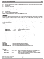
1
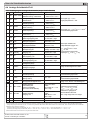
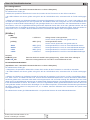
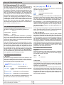
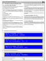
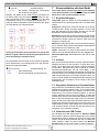
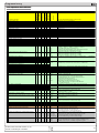
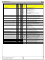
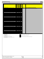
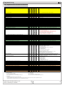
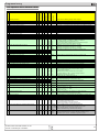
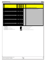
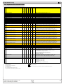
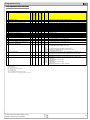
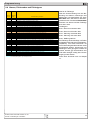
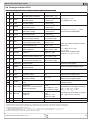
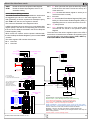
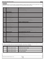
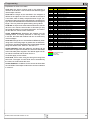
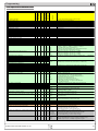
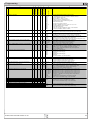
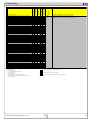
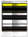
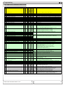
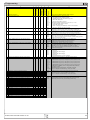
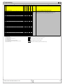
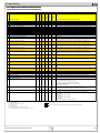
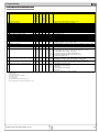
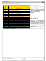
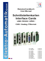
EN
About the interface cards
*SRE? Reads the Service Request Enable Register
*STB? Reads the Status Byte Register, which is cleared after reading
Bit 2: err, Error queue full; this queue is cleared by reading
it and the bit is also reset. The list can hold up to 4
of the last errors
Service Request (SRQ) generation
Bit 3: ques, Questionable status register is active (on or
more events have occured)
The GPIB controller automatically handles the actions that
are triggered by the bit rsv in the status register STB.
After generating a service request and subsequent query
with *STB? from the host, the register is cleared.
The scheme is illustrated in the diagramm below.
A SRQ is generated as soon as the bit rsv in the Status Byte
register (STB) is set and the corresponding bits for events
that can cause a SRQ are activated in the Service Request
Enable Register (SRE).
Which events can cause a service request is selected with
the Service Request Enable Register by the command *SRE
<CHAR>.
The status register STB consists of these bits:
Bit 4: Not used
Bit 5: esr, the standard Event Status Register (ESR), masked by the Event Status Enable Register (ESE), is
signalising that one or more events have occured
Bit 6: rsv, always active
Bit 7: oper, signalises, that one or more events have
occured and are stored in the Operation Status
Register
The event bits of the various registers report to the STB, if
events have occured that are enabled to be reported, by the
corresponding bits in the enable registers (*ESE, *SRE resp.
STAT:QUES:ENAB, STAT:OPER:ENAB).
Bit 0: Not used
Bit 1: Not used
Enable
Questionable Status
QUES
Positive transition
Negative transition
OUTPUT Buffer
data
data
data
Condition
Event
0
CC
CV
CP
CR
Reduce Power
1
2
3
4
5
Fct. at start
Fct. stepping
Fct. running
6
7
8
9
10
11
Input / Output on
Output Enable
12
13
14
z 0 1 D
z 0 1 D
z 0 1 D
z 0 1 D
z 0/1 0/1 0/U
z 0 0/0 0/U
z 0 0/0 0/U
z 0 0/0 0/U
0 0 0 0
0 0 0 0
0 0 0 0
z 1 1 D
z 0/1 0/1 0/U
0 0 0 0
0 0 0 0
Condition Enable
0
z 1
1
0 0
2
QYE
z 1
3
DDE
z 1
4
EXE
z 1
5
CME
z 1
6
0 0
7
Power on
z 1
OPC
Event
0
0
0
0
OR
0
0
0
0
Operation Status
OPER
Event
0
1
2
3
4
5
6
7
LOCAL
REMOTE
EXTERNAL
Function mode
Error Queue
Error
Error
0
<>0
err
mav
STATUS
STB
0
1
2
3
ques
4
5
esr
mss
oper
6
7
0
0
1
1
0
1
1
1
Service
Request
Enable
SRE
0
0
1
1
0
1
OR
1
rsv
Enable
Positive transition
Negative transition
Condition
MODE_A
MODE_B
MODE_AB
MODE_BAT
MODE_CR1
MODE_CR2
MODE_CV
data
Standard Event Status
Register
ESR
U = User defined
D = Set after power on
z = State of the indicated information
OPC = OPeration Complete bit
EXE= EXecution Error
QYE= QuerY Error
CME= CoMmand Errors
DDE= Device Depend Error
0
0
0
0
0
0
0
0 OR
0
0
0
0
0
0
0
8
9
10
11
12
13
14
0/z
0/z
0/z
0/z
0/z
0/z
0/z
0
z
z
z
0
z
0
0
0
0
0
0
0/1
0/1
0/1
0
0
0
0
0
1
0
0
0/1
0/1
0/1
0/1
0/1
0/1
0/1
0
1
1
1
0
1
0
0
0/D
0/D
0/D
0/D
0/D
0/D
0/D
0
D
D
D
0
U
0
0
© 2009, Elektro-Automatik GmbH & Co. KG
0
0
0
0
0
0
0
0 OR
0
0
0
0
0
0
0
Service Request
Generation
Legend:
CC/CV/CP/CR = currently active regulation mode
Reduce Power = power derating active (PSI 9000 series only)
Fct. at start/running/stepping = function manager status
Input / Output on = Input resp. output of the device is on
Output enable = auto-on for the output is activated
MODE_A/B/AB/BAT = actual operation mode, chosen by the rotary switch
MODE_CR1/CR2 = currently selected resistance range (CR1 is the smaller one)
LOCAL = device is in local mode, remote control is not allowed
REMOTE = device is remotely controlled by a digital interface card
EXTERNAL = device is controlled by the analogue interface card resp. the
built-in analog interface
Function mode = function manager active
66