1
THE PLASMON INFINITY
LD 6100
OPTICAL DISK DRIVE
User Manual
P/N 97654437 F
New features and changes to information in this document are indicated by change bars. Revision level is
indicated by the letter following the eight-digit document number. If a document has undergone major
modifications, change bars will not be inserted in the document.
Reproduction of this manual, or any portion of this manual, is prohibited without the express permission of
Plasmon Laser Magnetic Storage (LMS). Plasmon LMS reserves the right to make changes in this
document and the product referred to herein without prior notice.
©
1999 Plasmon Laser Magnetic Storage
WARNING
Always observe the following when installing, operating or maintaining
this product:
•
This unit must be connected to a power distribution system that has a
direct connection to earth ground (Terminated Terra [TT] network/
ground connected). This unit is not suitable for use on a floating
ground (Interrupted Terra [IT]) network.
•
The AC input power cord must be shielded and must have a minimum
current rating of 10 A with a nominal cross-section area of 0.75 sq mm
(reference: AWG #18) per conductor, 2 wires plus ground and product
safety approvals as required for use in the country in which the unit is
installed.
•
When the unit is mounted in an equipment rack or cabinet, be certain
that the internal temperature within the rack or cabinet does not
exceed the limits defined in the Product Specification or this
document.
•
To ensure the integrity of safety features of this unit, maintenance must
be performed only by qualified service personnel using designated
Plasmon LMS parts.
•
In case of fire or other emergency, isolate the units from the main
power by disconnecting the power plugs from their site power
receptacles. In situations where disconnecting the plugs is not
possible or practical, use the system main power disconnect to isolate
the units from the main power.
•
To prevent fire or shock hazard, do not expose this unit to rain or
moisture. Refer servicing to qualified technicians.
(German Translation)
WARNUNG
Bei der Installation, Bedienung und Wartung dieses Produkts, bitte
immer die folgenden Vorsichtsmaßnahmen treffen:
•
Dieses Gerät muß an ein Stromversorgungssystem angeschlossen
werden, das direkt mit einem Erdungsanschluß verbunden ist
(Terminated- Terra-Netz [TT]/mit Erdanschluß). Dieses Gerät kann
nicht an ein ungeerdetes Netz (Interrupted Terra [IT]) angeschlossen
werden.
•
Die Verbindungsschnur des Wechselstromeingangs muß entstört sein
und ihr Minimalstrom unter folgenden Bedingungen bei 10 A liegen:
Der Nennquerschnitt beträgt 0,75 mm je Leiter (Referenz: American
Wire Gauge Nr. 18), es bestehen 2 Drähte plus ein Erdanschluß und
das Produkt entspricht den im Land, in dem es aufgestellt wird,
geltenden Sicherheitsvorschriften.
•
Wird das Gerät in ein Gerätegestell oder einen Geräteschrank
eingebaut, ist darauf zu achten, daß die interne Temperatur im Gestell
oder Schrank nicht über die in den Produktspezifikationen oder
diesem Dokument angegebenen Grenzwerte hinausgeht.
•
Um ein ordnungsgemäßes Funktionieren der Sicherheitsmerkmale
dieses Gerätes zu gewährleisten, dürfen Wartungsarbeiten nur von
qualifiziertem Fachpersonal ausgeführt werden. Es sind darüber
hinaus nur Ersatzteile zu verwenden, die von der Firma Plasmon LMS
angegeben werden.
•
Im Falle eines Feuers oder in einem anderen Notfall sind die Geräte
vom Hauptnetz zu trennen, indem die Netzstecker aus den
Steckdosen am Einbauort gezogen werden. Ist ein Herausziehen der
Stecker nicht möglich oder zu umständlich, trennen Sie die Geräte mit
Hilfe des System- Hauptnetzabschalters vom Hauptnetz.
•
Um Feuer- oder Stromschlaggefahr zu vermeiden, ist dieses Gerät
niemals Regen oder Feuchtigkeit auszusetzen. Wartungsarbeiten
sind qualifiziertem technischen Personal zu überlassen.
RADIO/TV INTERFERENCE (USA)
The information in this section applies only to units in use within the United States:
This equipment generates and uses radio frequency energy and, if not installed and used properly, that is,
in strict accordance with the manufacturer's instruction, may cause interference to radio and television
reception. It has been type tested and found to comply with the limits for a Class A computing device in
accordance with the specifications of Part 15 of FCC Rules, which are designed to provide reasonable
protection against such interference in a residential installation. However, there is no guarantee that
interference will not occur in a particular installation. If this equipment does cause interference to radio or
television reception, which can be determined by turning the equipment off and on, the user is encouraged
to try to correct the interference by one or more of the following measures:
•
reorient the receiving antenna
•
relocate the equipment away from the receiver
•
plug the equipment into a different outlet so that equipment and receiver are on different branch
circuits.
If necessary, the user should consult the dealer or an experienced radio/television technician for additional
suggestions. A pamphlet by the FCC ‘How to Identify and Resolve Radio-TV Interference Problems' is
available from the US Government Printing Office, Washington, D.C., 20402, Stock No. 044-000-00345-4.
CDRH COMPLIANCE
LD 6100 contains a Class 1 Laser Product. This product complies with 21CFR Chapter 1, Subchapter J,
applicable at date of manufacture.
CANADIAN EMI COMPLIANCE
Canadian Department of Communications standards require that the following statement appear in
operating manuals for any digital apparatus imported into Canada:
This digital apparatus does not exceed the Class A limits for radio noise for digital apparatus set out in the
Radio Interference Regulations of the Canadian Department of Communications.
FRENCH TRANSLATION
Cet équipement digital ne dépasse pas les limites de la Classe A pour les interférences radioélectriques
des systémes digitaux fixées par les Réglements concernant les Interférences Radioélectriques établis par
le Ministére des Communications du Canada.
All Plasmon LMS products comply with the requirements of this standard.
Agency Compliance and Approval
For details on Agency Compliance and Approval refer to the LD 6100 Product Specification Manual.
TABLE OF CONTENTS
SCOPE
1
RELATED PUBLICATIONS
1
GENERAL DESCRIPTION
3
DRIVE CHARACTERISTICS
5
RACK MOUNT AND DESKTOP CONFIGURATIONS
TOWER CONFIGURATION
FILENET JUKEBOX CONFIGURATION
CYGNET JUKEBOX CONFIGURATION
DIMENSIONS AND WEIGHTS
TEMPERATURE, HUMIDITY AND ALTITUDE
SHOCK AND VIBRATION
AC POWER REQUIREMENTS
AC GROUND
AC POWER CORD
POWER SUPPLY OUT-OF-RANGE
PROTECTION FEATURES
TILT RANGE
HEAT DISSIPATION
PARTICULATE LIMITS
WARNING LABELS
5
8
11
14
16
17
18
18
19
19
UNPACKING AND REPACKING INSTRUCTIONS
21
UNPACKING THE LD 6100
DESKTOP, RACK MOUNT AND
JUKEBOX CONFIGURATIONS
TOWER CONFIGURATION
INSPECTING THE LD 6100
REPACKING THE LD 6100
DESKTOP, RACK MOUNT AND
JUKEBOX CONFIGURATIONS
TOWER CONFIGURATION
INSTALLATION AND DE-INSTALLATION
INSTALLATION REQUIREMENTS
QUICK RELEASE RACK MOUNT KIT INSTALLATION
SCSI BUS CONSIDERATIONS
CONNECTING POWER AND SCSI CABLES
CONNECTING THE POWER CORD
CONNECTING MULTIPLE DEVICES
CONNECTING A SINGLE DEVICE
CONNECTOR VERIFICATION
QUICK RELEASE RACK MOUNT DE-INSTALLATION
19
19
19
19
20
21
21
23
25
25
26
28
29
29
30
42
44
44
44
45
46
46
OPERATING INSTRUCTIONS
CONTROLS AND INDICATORS
POWER-ON PROCEDURE
MODES OF OPERATION
OPERATING MODE
CONFIGURATION MODE
TEST MODE
MEDIA CARTRIDGE HANDLING
SETTING THE WRITE PROTECTION SWITCH
AFFIXING LABELS TO THE MEDIA CARTRIDGE
MANUAL RELEASE MECHANISM
OPERATOR MAINTENANCE
INSPECTING AND CLEANING FAN AND BLOWER FILTERS
REPLACING FUSES
MEDIA CLEANING
MEDIA CLEANING USING CLEANING KIT P/N 97662550
49
49
51
52
52
55
76
77
79
80
81
83
83
84
86
86
ACCESSORIES
87
APPENDIX A
91
GERMAN TRANSLATIONS/
ÜBERSETZUNGEN INS DEUTSCHE
91
SCOPE
This User Manual describes unpacking, installing, operating, and maintaining the LaserDrive (LD) 6100
High-Performance Optical Disk Drive.
RELATED PUBLICATIONS
PUBLICATION
PART NUMBER
LM 6000 Media Product Specification
97647044
LD 6100/LF 6600/LF 6602 Product Specification
97653977
LD 6100/LF 6600/LF 6602 SCSI Interface Specification
97653978
LD 6100 Hardware Maintenance Manual
97653979
WARRANTY STATEMENT
The LD 6100 is warranted as stated in the purchase agreement between Plasmon and it’s customer,
or the Plasmon sales order acknowledgment, whichever is applicable.
The Plasmon LMS quality system is in compliance and registered to ISO 9002. The LD 6100 is
manufactured from new parts, or remanufactured parts.
LD 6100 warranty does not cover defects or damage caused by the use of unauthorized parts or
repairs or improper use or maintenance. Repairs or replacements not covered by the warranty will
be invoiced at LMS’ then current prices.
The warranty is void when installation, service or repairs are performed by unauthorized
personnel; when the product is affected by unauthorized alterations, modifications or other
tampering or misuse; when the product is incorporated into a system which causes or involves
any changes in the physical, mechanical or electrical arrangement of the product; or when the
product is not used in accordance with its applicable specifications.
The term, authorized personnel, is defined as those persons who have been trained by Plasmon
LMS Technical Services.
97654437 F
Page 1
PLASMON LASER MAGNETIC STORAGE - LD 6100 USER MANUAL
Page 2
GENERAL DESCRIPTION
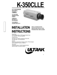
The Plasmon Infinity LaserDrive 6100 (LD 6100) is a write once read many (WORM), high-capacity optical
disk drive which uses a removable 300-mm (12-in.), LM 6000 optical media cartridge with storage capacity
of up to 12 GBytes. The LD 6100 can also read LM 4000 media. The LD 6100 is available in a Rack Mount,
Desktop, Tower, FileNet ® Jukebox and Cygnet ® Jukebox configurations offering support for varied
operating orientations and installation environments (see figure below).
RACK MOUNT
CONFIGURATION
CYGNET JUKEBOX
CONFIGURATION
DESKTOP
CONFIGURATION
TOWER
CONFIGURATION
FILENET JUKEBOX
CONFIGURATION
LD 6100 Configurations
97654437 F
Page 3
The LD 6100 supports a sustained read transfer rate of 2.7 MBytes/sec with error correction and defect
management capabilities to maintain data integrity and manage media flaws. The drive also supports a
sustained write transfer rate of 1.3 MBytes/sec with data verification.
A Drive Operator Console (DOC) located on the front panel of the drive provides user control of drive
operation and configuration as explained in the Operating Instruction section of this manual.
Operating messages are presented on the alphanumeric display in English, French or German. The
language used is selectable.
The Auxiliary Diagnostic Port (ADP) can be used to download updates to the drive firmware in the field.
Refer to the LD 6100/LF 6600/LF 6602 Product Specification (P/N 97653977) for more information. The
ADP is located on the front panel of the Rack Mount, the Desk Top and the Tower configurations. The ADP
may be located on the rear panel of the Cygnet Jukebox and the Filenet configurations.
The LD 6100 drive implements the Small Computer System Interface (SCSI) via standard SCSI-2 micro
connectors located on the rear panel. Single-ended and differential interface options are available, and the
interface can be changed in the field. Both the single-ended and differential controllers support
asynchronous or synchronous data transfer operations.
Preventive maintenance for the LD 6100 is minimal. Corrective maintenance is simplified by internal
diagnostic firmware which detects, isolates and reports malfunctions to the operator and identifies the Field
Replaceable Unit (FRU).
LM 6000 media is interchangeable between the LD 6100, LF 6600, and the LF 6602. The LX 6XXX series
of drives will also read LM 4000 media written by the Plasmon LMS 4000 series of optical drive products
(except for media with serial numbers less than X0010000, where X designates an A or B).
PLASMON LASER MAGNETIC STORAGE - LD 6100 USER MANUAL
Page 4
DRIVE CHARACTERISTICS
This section describes the LD 6100 Rack Mount, Desktop, Tower, FileNet Jukebox and Cygnet Jukebox
configurations. All LD 6100 configurations have the same major internal subassemblies.
RACK MOUNT AND DESKTOP CONFIGURATIONS
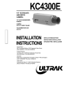
The LD 6100 Rack Mount configuration is designed for horizontal operation and slide mounting in an EIA
standard 19-in. rack. The Rack Mount configuration is installed in a rack using the Quick Release Rack
Mount Kit (refer to the Installation section of this manual).
LD 6100 Rack Mount Drive
97654437 F
Page 5
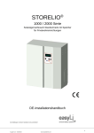
The LD 6100 Desktop configuration (see figure below) is designed for horizontal operation as a standalone device on a table top. The Desktop configuration includes an enclosure and rubber feet.
LD 6100 Desktop Drive
PLASMON LASER MAGNETIC STORAGE - LD 6100 USER MANUAL
Page 6
The figure below illustrates the front panel layout. The ADP connector is located beside the DOC but is
concealed by the Bezel.
BEZEL
MEDIA CARTRIDGE LOADING DOORS
ADP
DOC
LD 6100 Rack Mount and Desktop Front Panel Layout (Rack Mount Version Shown)
The LD 6100 Rack Mount and Desktop rear panel layout includes a DOC/ADP Blank Panel, MCLI Blank
Panel, AC Power Switch, Receptacle, SCSI-2 I/O Panel Assembly and a ground connector. The figure
below illustrates the rear panel layout. A Fan Grill and filter element are installed over the fan vent to filter
out contaminants from cooling air entering through the rear panel.
AC POWER
SWITCH
AC POWER
RECEPTACLE
DOC/ADP
BLANK PANEL
GROUND
CONNECTOR
MCLI
BLANK PANEL
SCSI-2 I/O
CONNECTORS
LD 6100 Rack Mount Rear Panel
97654437 F
Page 7
TOWER CONFIGURATION
The Tower configuration (see the next figure) is designed for vertical operation as a stand-alone device on
an open floor or beside a desk. The Tower configuration includes an enclosure for both the LD 6100 and
the pedestal. The pedestal is supported by four casters which can be locked to prevent unintentional
movement.
LD 6100 Tower Configuration
PLASMON LASER MAGNETIC STORAGE - LD 6100 USER MANUAL
Page 8
The illustration below shows the front panel of the LD 6100 Tower configuration and identifies the location
of the DOC and ADP connector. The ADP connector is located below the DOC but is concealed by the
bezel.
MEDIA CARTRIDGE
LOADING DOORS
DOC
ADP
BEZEL
LD 6100 Tower Front Panel Layout
97654437 F
Page 9
The figure below illustrates the rear panel of the LD 6100 Tower configuration and identifies the location of
the AC power switch, Receptacle, ground connector, SCSI-2 I/O Panel Assembly, DOC/ADP Blank Panel
and MCLI Blank Panel. A Fan Grill and filter element are installed over the fan vent to filter contaminants
from cooling air entering through the rear panel.
SCSI- 2 I/O
PANEL
ASSEMBLY
AC POWER
RECEPTACLE
MCLI BLANK
PANEL
FAN GRILL AND
FILTER ELEMENT
AC POWER
SWITCH
DOC
BLANK
PANEL
GROUND
CONNECTOR
PEDESTAL
Rear View of LD 6100 Tower
PLASMON LASER MAGNETIC STORAGE - LD 6100 USER MANUAL
Page 10
FILENET JUKEBOX CONFIGURATION
The FileNet Jukebox configuration (see figure below) does not have a Bezel and is designed for vertical
mounting and operation in a FileNet Jukebox. The FileNet Jukebox configuration has the same major
assemblies as the other LD 6100 configurations but is configured for use in a FileNet Jukebox by adding
the MCLI connector and Registration Panel.
FileNet Jukebox Configuration
97654437 F
Page 11
The following figure illustrates the front panel of the FileNet jukebox configuration and identifies the
location of the DOC/ADP Blank Panel. The DOC and ADP connector are located on the rear panel, so the
DOC/ADP Blank Panel is used to cover the DOC and ADP mounting holes. A special Registration Panel is
installed on the FileNet jukebox configuration in place of the Bezel.
DOC
REGISTRATION PANEL
MEDIA CARTRIDGE
LOADING SLOT
LD 6100 FileNet Jukebox Front Panel
PLASMON LASER MAGNETIC STORAGE - LD 6100 USER MANUAL
Page 12
The figure below illustrates the rear panel of the LD 6100 FileNet jukebox configuration and identifies the
location of the AC Power Switch, Receptacle, ground connector, SCSI-2 I/O Panel Assembly, DOC, ADP
connector and the MCLI connector. A Fan Grill and filter element are installed over the fan vent to filter
contaminants from cooling air entering through the rear panel.
SCSI-2 1/O
CONNECTORS
AC POWER
RECEPTACLE
MCLI I/O
CONNECTOR
FAN GRILL AND
FILTER ELEMENT
AC POWER
SWITCH
DOC
GROUND
CONNECTOR
ADP
CONNECTOR
LD 6100 FileNet Jukebox Rear Panel
97654437 F
Page 13
CYGNET JUKEBOX CONFIGURATION
The Cygnet Jukebox configuration (see figure below), which does not have a Bezel or Registration Panel,
is designed for horizontal mounting and operation in a Cygnet Jukebox. The Cygnet Jukebox configuration
has the same major assemblies as the other LD 6100 configurations but is adapted for use in a Cygnet
Jukebox by adding an MCLI connector.
Cygnet Jukebox Drive
The next figure illustrates the front panel of the Cygnet jukebox configuration and identifies the location of
the DOC/ADP Blank Panel. The DOC and ADP connector are located on the rear panel, so the DOC/ADP
Blank Panel is used to cover the DOC and ADP mounting holes.
DOC/ADP
BLANK PANEL
MEDIA CARTRIDGE
LOADING PORT
LD 6100 Cygnet Jukebox Front Panel
PLASMON LASER MAGNETIC STORAGE - LD 6100 USER MANUAL
Page 14
The figure below illustrates the rear panel of the LD 6100 Cygnet Jukebox configuration and identifies the
location of the AC Power Switch, Receptacle, ground connector, SCSI-2 I/O Panel Assembly, DOC, ADP
connector and the MCLI connector. A Fan Grill and filter element are installed over the fan vent to filter
contaminants from cooling air entering through the rear panel.
DOC
FAN GRILL AND
FILTER ELEMENT
ADP
CONNECTOR
GROUND
CONNECTOR
AC POWER
SWITCH
AC POWER
RECEPTACLE
SCSI-2 1/O
CONNECTORS
MCLI
CONNECTOR
LD 6100 Cygnet Jukebox Rear Panel
97654437 F
Page 15
DIMENSIONS AND WEIGHTS
The following table lists the dimensions of the LD 6100 Rack Mount, Desktop and Tower, FileNet and
Cygnet Jukebox configurations. These dimensions do not include extending media cartridges or interface
cabling. Refer to the LD 6100 Product Specification (P/N 97653977) for the dimensions of the FileNet and
Cygnet Jukebox configurations with a media cartridge and interface cabling.
Dimensions of the LD 6100 Configurations
DIMENSION
RACKMOUNT
DESKTOP
TOWER
FILENET
CYGNET
Chassis Length:
60.9 cm
(24.0 in)
64.3 cm
(25.3 in)
64.3 cm
(25.3 in)
64.3 cm
(25.3 in)
64.3 cm
(25.3 in)
65.3 cm
(25.7 in)1
67.3 cm
(26.5 in)2
67.3 cm
(26.5 in)2
67.3 cm
(26.5 in)3
With Mounting Kit:
66.6 cm
(26.2 in)4
Chassis Width:
With Mounting Kit:
43.0 cm
(16.9 in)
43.0 cm
(16.9 in)
16.9 cm
(6.7 in)
47.5 cm
(18.7 in)1
48.6 cm
(19.1 in)2
18.8 cm
(7.4 in)2
16.9 cm
(6.7 in)
43.0 cm
(16.9 in)
16.9 cm
(6.7 in)
30.5 cm
(12.0 in)4
Chassis Height:
16.9 cm
(6.7 in)
16.9 cm
(6.7 in)
48.6 cm
(19.1 in)
43.0 cm
(16.9 in)
With Mounting Kit:
17.8 cm
(7.0 in)1
18.8 cm
(7.4 in)5
63.2 cm
(24.8 in)6
43.8 cm
(17.2 in)3
Mounting Depth
60.9 cm
(24.0 in)7
1 Includes the Bezel.
2 Includes the Bezel and chassis skin.
3 Includes the Registration Panel.
4 The pedestal and pedestal skin.
5 Includes the rubber feet.
6 Includes the chassis skin, pedestal and casters.
7 Depth to which the drive extends into the mounting rack.
The following weight specifications do not include interface cabling or optical media:
Rack Mount
30.5 kg
(67 lbs)
Desktop
35.9 kg
(79 lbs)
Includes Enclosure
Tower
41.8 kg
(92 lbs)
Includes Enclosure and Pedestal
FileNet Jukebox
31.4 kg
(69 lbs)
Includes Registration Panel
Cygnet Jukebox
30.5 kg
(67 lbs)
PLASMON LASER MAGNETIC STORAGE - LD 6100 USER MANUAL
Page 16
TEMPERATURE, HUMIDITY AND ALTITUDE
The following table lists the LD 6100 operating, nonoperating, storage and transit limits for temperature,
humidity, and altitude.
Temperature, Humidity and Altitude Limits
OPERATING
NONOPERATING
STORAGE/TRANSIT1
10° to 42° C 2
(50° to 108° F)
-40° to 66° C
-40° to 151° F)
-40° to 66° C
-40° to 151° F)
Maximum Rate of
Change
11° C/hr (20° F/hr)
20° C/hr (36° F/hr)
20° C/hr (36° F/hr)
Humidity
(Noncondensing)
10 to 99%
5 to 95%
5 to 95%
Maximum Rate of
Change
10%/hr
10%/hr
10%/hr
Maximum Wet Bulb
Temperature 3
28° C (82° F)
46° C (115° F)
46° C (115° F)
Minimum Dew Point
2° C (35.6° F)
2° C (35.6° F)
2° C (35.6° F)
CONDITION
Temperature
Altitude 4
Storage:
-300 to 3000 m
(-984 to 9840 ft)
Transit:
-300 to 2000 m
(-984 to 6562 ft)
with media
-300 to 3000 m
(984 to 9840 ft)
Storage:
-300 to 3000 m
(984 to 9840 ft)
Transit:
-300 to 12,000 m
(-984to 40,000 ft)
1 Storage specifications are for 90 days maximum in Plasmon LMS packaging. No condensation is permitted. Transit specifications are
based on a maximum 1-week period in a factory-sealed container.
2 Maximum operating temperature is 42 _C for a free-standing drive at sea level unless otherwise stated. Maximum operating temperature
is derated linearly above 300 m altitude to 38 _C at 2,000 m altitude.
3 See the LD 6100/LF 6600/LF 6602 Product Specification (P/N 97653977) for more information concerning the temperature and humidity
operating range.
4 Media is limited to 2000 m. For conditions and limits pertaining to the media, refer to the LM 6000 Media Specification (P/N 97647044).
97654437 F
Page 17
SHOCK AND VIBRATION
The following table lists the conditions and limits for shock and vibration.
Shock and Vibration Criteria and Limits
OPERATING
NONOPERATING1
STORAGE/TRANSIT2
5 to 22 Hz 0.01 in
double amplitude,
22 to 500 Hz
0.25 g peak
5 to 44 Hz, 0.03 in
double amplitude,
44 to 500 Hz
3.0 g peak
5 to 44 Hz, 0.03 in
double amplitude,
44 to 500 Hz
3.0 g peak
CONDITION
Swept Vibration
(bidirectional)
1 Octave/Min
Shock 3
(host retries may be
required and drive
performance may
degrade during test)
10 - msec half sine
pulse of 10.0 g peak
Unpacked (3 axis)
5 - msec half sine
pule of 20 g peak
Packed on Pallet
46 - cm (18 - in) drop
test flat
1 With media removed
2 In Plasmon LMS-approved packaging
3 Shock repetition rate should be limited to allow mechanical system transients to subside between pulses.
AC POWER REQUIREMENTS
The LD 6100 has an AC power switch with an integral grounded power connector and fuses located on the
rear panel. Two spare fuses are included within the power connector. Refer to Replacing Fuses section for
the fuse replacement procedure.
The power supply will operate with the line voltages listed in the following table. The power supply is auto
ranging and does not require mechanical switching for input voltage or frequency selection.
AC Circuit Requirements
FREQUENCY
AC VOLTAGE
CURRENT
(TYPICAL)
SPIN - UP
SURGE1
MINIMUM
SERVICE
RATINGS
47 to 66 Hz
86.7 to 128 V
1.5 A
5.5 A
15 A
47 to 66 Hz
173.4 to 268 V
0.75 A
2.75 A
15 A
1 Less than 1 sec, cold start
PLASMON LASER MAGNETIC STORAGE - LD 6100 USER MANUAL
Page 18
AC GROUND
The LD 6100 AC power cord connects the LD 6100 to safety ground through the site AC power system.
The site AC power system must tie this safety ground connection to earth ground. All site AC power
connections must be maintained on the same safety ground.The line ground connector located on the rear
panel can also be used to tie chassis ground to earth ground. This ground connector is a 6-mm (0.24-in)
M4 stud with a nut and lock washer.
AC POWER CORD
The type of AC power cord that is supplied with the LD 6100 is based on the configuration ordered.
POWER SUPPLY OUT-OF-RANGE PROTECTION FEATURES
The LD 6100 power supply provides over and under voltage protection, over current protection, power
failure detection and over temperature protection. Should an out-of-range condition be detected, the LD
6100 will shut down the DC outputs of the power supply. For example, if the internal temperature of the
power supply reaches 80° C +/- 5° C (176° F +/- 9° F), the power supply will shut down. Once the situation
has been corrected, power can be restored by turning the AC power switch to the off position and then to
the on position again.
TILT RANGE
The LD 6100 Rack Mount, Desktop and Cygnet Jukebox configurations will operate over a tilt range of 10
degrees from the horizontal position. The Tower and FileNet Jukebox configuration will operate over a tilt
range of 10 degrees from the vertical position. The LD 6100 is not designed for dynamic tilt environments.
HEAT DISSIPATION
The drive will typically present a heat load of 146 kg-calories/hr (580 BTU/hr) during a read/write operation.
When media cartridges are inserted, loaded, spun up, spun down, unloaded and removed at the LD 6100's
maximum rate in a jukebox environment, the LD 6100 will typically present a heat load of 182 kg-calories/
hr (725 BTU/hr).
PARTICULATE LIMITS
The LD 6100 is designed for use in an office or computer room. The environment must have a low dust
level. The LD 6100 filters incoming air for cooling to reduce the quantity of particles entering the drive;
however, the filter is not effective against small particles (including tobacco smoke) which will become
deposited on optical components and media, causing degradation in drive performance. Refer to the
Operator Maintenance section for media cleaning and air filter cleaning instructions.
97654437 F
Page 19
WARNING LABELS
The LD 6100 is classified as a laser product. As such, it is subject to United States Federal requirements
covering laser products. The warning labels shown in the figure below are necessary to ensure compliance
with Federal regulations and must not be removed from the LD 6100.
LASER CLASS LABEL
FCC, RFI, CLASS A
LABEL
LASER DANGER
LABEL
CANADIAN CLASS A
COMPLIANCE LABEL
Locations of the LD 6100 Warning Labels
PLASMON LASER MAGNETIC STORAGE - LD 6100 USER MANUAL
Page 20
UNPACKING AND REPACKING
INSTRUCTIONS
If the Laser Drive’s shipping carton shows evidence of rough handling or damage, return the unit in its
carton to your supplier and request a replacement.
UNPACKING THE LD 6100
Each LD 6100 is shipped on a pallet in a shipping carton with foam packing material which protects the unit
from shock and vibration.
After you receive your LD 6100, inspect the shipping carton for damage before unpacking the unit to
substantiate a claim with the carrier if the unit is damaged. Retain all original packing materials and
receipts for possible reshipment.
WARNING
The LD 6100 must be unpacked, repacked and transported by two
persons. Physical injury can result if one person attempts to transport
or lift the LD 6100. A wheeled cart is recommended for transporting
the LD 6100 within a building. Precautions should be taken to guard
against sudden bumps and jarring.
DESKTOP, RACK MOUNT AND JUKEBOX CONFIGURATIONS
To unpack the LD 6100 Desktop, Rack Mount and Jukebox configurations, refer to the next figure and
perform the following procedure:
1) Cut the bands that secure the outer carton to the lower carton.
2) Lift the outer carton away from the lower carton and pallet.
3) Remove the small options and accessories tray.
The shipping carton will also contain a Quick Release Rack Mount Kit if it is ordered with the LD 6100 Rack
Mount configuration. If you are unpacking an LD 6100 Rack Mount configuration, check for the Quick
Release Rack Mount Kit carton and remove it at this time.
4) Lift both foam cushions away from the LD 6100.
5) Remove the ESD packing material.
6) Carefully lift and remove the LD 6100 from the shipping carton and place it on a flat
surface.
97654437 F
Page 21
OUTER
CARTON
OPTION/
ACCESORY
TRAY
FOAM
CUSHION
MOUNTING/SLIDE
KIT
(RACK MOUNT
CONFIGURATION)
FRONT FOAM
CUSHION
ESD PACKING
MATERIAL
LD 6100
FOAM PADS
LOWER
CARTON
PALLET
Unpacking the LD 6100 Desktop, Rack Mount and Jukebox Configurations
PLASMON LASER MAGNETIC STORAGE - LD 6100 USER MANUAL
Page 22
TOWER CONFIGURATION
To unpack the LD 6100 Tower configuration, refer to the next figure and perform the following procedure:
1) Cut the bands that secure the carton to the lower portion pallet.
2) Carefully lift the carton up and away from the pallet while supporting the wooden hinged
ramp.
3) Lower the ramp to the floor.
4) Remove the options and accessories tray.
5) Lift both foam cushions away from the LD 6100.
6) Remove the ESD packing material.
WARNING
The LD 6100 must be unpacked, repacked and transported by two
persons. Physical injury can result if one person attempts to transport
or lift the LD 6100. A wheeled cart is recommended for transporting
the LD 6100 within a building. Precautions should be taken to guard
against sudden bumps and jarring.
Ensure that all four casters are locked. Lift the front end of the LD 6100 high enough to remove the bottom
cushion.
7) Remove the foam bumper.
8) Remove the bottom cushion.
9) Lower the LD 6100 onto the pallet.
10) Unlock the casters and roll the LD 6100 down the ramp to its installation location.
11) Lock the casters once you have the LD 6100 situated at its installation location.
97654437 F
Page 23
CARTON
REAR FOAM
CUSHION
OPTIONS/
ACCESSORIES
TRAY
ESD PACKING
MATERIAL
FRONT FOAM
CUSHION
LD 6100
FOAM
BUMPER
BOTTOM
CUSHION
HINGED
WOODEN
RAMP
PALLET
Unpacking and Repacking the LD 6100 Tower Configuration
PLASMON LASER MAGNETIC STORAGE - LD 6100 USER MANUAL
Page 24
INSPECTING THE LD 6100
The following items should be included with each LD 6100:
•
one LD 6100 drive
•
one AC power cord
•
one User Manual
These items are offered as options:
•
LM 6000 media cartridges
•
a Bezel kit
•
I/O cables
•
terminators
After unpacking the LD 6100, check for:
•
damage to the chassis cover, chassis and bezel
•
damage to connectors
•
dislocated or broken controls and indicators
Report all discrepancies, missing items and damaged equipment to your supplier.
If condensation exists on the drive, allow the moisture to evaporate by exposing the LD 6100 to the
operating environment for at least 6 hrs before powering on the unit.
REPACKING THE LD 6100
The LD 6100 should be repacked using the original packing material. Perform the following procedures to
repack the LD 6100 for shipment.
CAUTION
The baseplates must be in the closed position before the drive can be
reshipped to prevent lifter mechanism damage. To close the
baseplates, select the "Park Drive" option in the Configuration mode
or perform the manual procedure as described in step 2).
Shipping the LD 6100 without closing the baseplates may result in
damage to the drive, which is not covered under warranty.
97654437 F
Page 25
DESKTOP, RACK MOUNT AND JUKEBOX CONFIGURATIONS
1) Remove any media cartridge from the drive. (To remove a cartridge from a drive that is not
operational, refer to the Manual Release Mechanism section).
2) Select the "Park Drive" option, as explained in the Performing Diagnostic Operation
section of this manual, to prepare the LD 6100 for shipment. If the drive is not functional,
follow these steps:
a.) Ensure that the AC power switch is set to the OFF (O) position.
b.) Remove the Bezel Assembly by grasping both sides of the Bezel Assembly
and pulling it up, away from the chassis.
c.) Turn the Manual Release Knobs located at the front of the drive in a
counterclockwise direction until free rotation is restricted.
UPPER MANUAL
RELEASE KNOB
DIRECTION OF
ROTATION
LOWER MANUAL RELEASE KNOB
Closing the Upper and Lower Baseplates Before Shipment
d.) Reinstall the Bezel Assembly onto the front panel by positioning the Bezel
Assembly near the front of the drive with the bottom of the Bezel angled in closer
to the drive. This ensures that the bottom Velcro fasteners of the Bezel
Assembly are aligned with the bottom Velcro fasteners of the drive. Begin sliding
the Bezel Assembly onto the drive, lifting the Bezel Assembly so that the bottom
flange of the Assembly contacts the bottom surface of the drive. Press the Bezel
Assembly firmly onto the front of the unit. This action will center the Velcro
fasteners for greater adhesion.
PLASMON LASER MAGNETIC STORAGE - LD 6100 USER MANUAL
Page 26
Re-installing Bezel Assembly
3) Remove all the packing material from the carton except the packing material in the bottom
of the carton.
WARNING
The LD 6100 must be repacked and transported by two persons.
Physical injury can result if one person attempts to transport or lift the
LD 6100. A wheeled cart is recommended for transporting the LD
6100 within a building. Precautions should be taken to guard against
sudden bumps and jarring.
4) Place the LD 6100 into the lower carton.
5) Place the ESD packing material on top of the drive.
6) Position the foam cushions around the drive.
7) Place the power and interface cables, User Manual and other accessories into the options
and accessories tray and place this tray on the foam cushions.
8) If packing an LD 6100 Rack Mount configuration, place the Slide Mounting Kit onto the
foam cushions at this time.
9) Place the outer carton over the tray and drive.
10) Strap the carton to the pallet at each end.
97654437 F
Page 27
TOWER CONFIGURATION
1) Remove any media cartridge from the drive.
CAUTION
The baseplates must be in the closed position before the drive can be
reshipped to prevent lifter mechanism damage. To close the
baseplates, select the "Park Drive" option in the Configuration mode
or perform the manual procedure as described in step 2).
2) Select the "Park Drive" option, as explained in the Performing Diagnostic operation section
of this manual, to prepare the LD 6100 for shipment. If the drive is not functional, follow
these steps:
a.) Ensure that the AC power switch is set to the OFF (O) position.
b.) Remove the Bezel Assembly.
c.) Turn the Manual Release Knobs located at the front of the drive in a
counterclockwise direction until free rotation is restricted.
d.) Re-install the Bezel Assembly onto the front panel.
WARNING
The LD 6100 must be repacked and transported by two persons.
Physical injury can result if one person attempts to transport or lift the
LD 6100. A wheeled cart is recommended for transporting the LD
6100 within a building. Precautions should be taken to guard against
sudden bumps and jarring.
3) Unlock the casters and carefully roll the drive to its packing site.
4) Remove all packing material from the carton except the bottom cushion
5) Lower the carton's ramp to the floor.
6) Carefully roll the Tower up the ramp and onto the bottom cushion and lock the casters.
7) Move the ramp into its vertical position in the pallet.
8) Place the ESD packing material on top of the drive and position the foam bumper, front
foam cushion and rear foam cushion.
9) Place the power and interface cables, User Manual and other accessories into the options
and accessories tray and place this tray on the foam cushions.
10) Place the carton over the drive.
11) Strap the carton to the pallet at each end.
PLASMON LASER MAGNETIC STORAGE - LD 6100 USER MANUAL
Page 28
INSTALLATION AND DEINSTALLATION
INSTALLATION REQUIREMENTS
Adequate clearances must be provided around the LD 6100 during installation to prevent crimping and
bending of cables and to ensure that future servicing can be performed safely. These clearances are also
required to properly ventilate the LD 6100 and to provide operator access to the Drive Operator Console
(DOC) and to the front bezel for inserting and removing cartridges.
CAUTION
When the LD 6100 is mounted in an equipment rack or cabinet,
ensure that the internal temperature within the rack or cabinet does
not exceed the operating limits defined in the Product Specification
and this document. Vertically stacked units require special attention at
the top area where higher temperatures exist.
The LD 6100 must be connected to a power distribution system that
has a direct connection to earth ground (Terminated Terra [TT]
network/ground connected). This unit is not suitable for use on a
floating ground (Interrupted Terra [IT] network).
Ensure the drive is connected to a power distribution system with an
adequate current-handling capacity.
The following table lists the clearances required for air circulation, cartridge insertion/removal,
maintenance and cable routing.
LD 6100 Installation Clearances
FRONT
REAR1
SIDES2
TOP3
51 cm (20 in) 4
12.7 cm (5 in.)
12.7 cm (5 in.)
90 cm (36 in.)
Rack
Mount
116 cm (46 in.) 5
12.7 cm (5 in.)
12.7 cm (5 in.)
90 cm (36 in.)
Tower
51 cm (20 in.) 4
12.7 cm (5 in.)
12.7 cm (5 in.)
12.7 cm (5 in.)
Jukebox
116 cm (46 in.)
12.7 cm (5 in.)
12.7 cm (5 in.)
90 cm (36 in.)
LD 6100
Desktop
1
BOTTOM
12.7 cm (5 in.)2
12.7 cm (5 in.)
Required to avoid bending or crimping cables. 2 Required for proper ventilation. 3 Required to remove covers for servicing. 4 Required to access DOC and for media loading and unloading. 5 Required to fully extend the LD 6100 Rack
Mount on its slides.
97654437 F
Page 29
Ensure the installation site is able to support a volumetric air flow of 3.2 m3/min (112 cfm). Also ensure that
the operating environment is free from dust and particulates, such as tobacco smoke.
WARNING
To prevent fire or shock hazard, do not expose the LD 6100 to rain or
moisture. Refer servicing to qualified technicians. In case of fire or
other emergency, isolate the units from the main power by
disconnecting the power plugs from their site power receptacles. In
situations where disconnecting the plugs is not possible or practical,
use the system main power disconnect to isolate the unit from the
main power. Use of controls or adjustments, or performance of
procedures other than those specified herein may result in exposure
to hazardous laser radiation.Do not disable the safety interlocks in the
unit. Do not stare directly into the laser beam or its reflection on any
reflecting mirror-like surface. Invisible laser radiation can be emitted if
the unit is open and safety interlocks are defeated.
QUICK RELEASE RACK MOUNT KIT INSTALLATION
This procedure provides the instructions for installing an LD 6100 into a standard EIA 19-in. rack. Before
the LD 6100 is installed, ensure that the site installation requirements are met (refer to the Installation
Requirements section in this manual). The Desktop, Tower, FileNet Jukebox and Cygnet Jukebox
configurations are shipped with the appropriate enclosure and hardware installed; the Mounting Kit for the
Rack Mount configuration must be installed in the field.A minimum of 116 cm (46 in.) is required at the front
of the rack during installation and to fully extend the LD 6100 on the slides.
WARNING
Installing the LD 6100 into a rack requires two people to lift the drive
into mounting position. After the LD6100 is installed in the rack, the
drive must be properly grounded to avoid exposing personnel to
electric shock during operation.
The Quick Release Rack Mount Kit consists of the following:
•
one left Slide Assembly
•
one right Slide Assembly
•
four Mounting Brackets
•
six M4 x 6 screws
•
eight M4 X 8 screws
•
eight M4 nuts
PLASMON LASER MAGNETIC STORAGE - LD 6100 USER MANUAL
Page 30
•
eight M4 spring lock washers
•
eight M4 flat washers
•
eight 10-32 x 5/16 in. screws
•
eight M5 X 8 screw/washer assemblies
•
four 10-32 nut plates
•
eight No. 10 flat washers
Refer to the next figure for an illustration of the Quick Release Kit's major parts.
NUT PLATE
(4 PLACES)
MOUNTING BRACKET
(4 PLACES)
LEFT SIDE
ASSEMBLY
RIGHT
SLIDE
ASSEMBLY
QUICK
DISCONNECT
OUTER SLIDE
MEMBER
INTERMEDIATE
SLIDE MEMBER
ACCESS SLOT
INNER SLIDE
MEMBER
SLIDE RELEASE
LATCHES
Contents of Rack Mount Quick Release Kit
97654437 F
Page 31
Each Slide Assembly is composed of an Inner Slide Channel, Intermediate Slide Channel and an Outer
Slide Channel. The left and right slide assemblies are mirror images of each other, but care must be
exercised to ensure that both slide assemblies are properly oriented when installed into a rack.
The first step in the installation involves separating the left and right Inner Slide Channels from their
respective slide assemblies. The Inner Slide Channels are locked to the Intermediate Slide Channels by
the Slide Release Latch and the Inner Slide Release Button. The Slide Release Latch is located at the
front of the Inner Slide Channel and the Inner Slide Button is located on the inside of the Inner Slide
Channel.
LEFT OUTER SLIDE CHANNEL
SLIDE RELEASE LATCH
LEFT INNER SLIDE
CHANNEL
LEFT INTERMEDIATE
SLIDE CHANNEL
INNER SLIDE CHANNEL
RELEASE BUTTON
Separating the Inner Slide Channel from the Intermediate Slide Channel
1) Lift up the Slide Release Latch at the front of the Inner Slide Channels and pull the Inner
Slide Channels out until they stop.
2) Depress the Inner Slide Channel Release Buttons and then pull the Inner Slide Channels
out of the Intermediate Slide Channels.
PLASMON LASER MAGNETIC STORAGE - LD 6100 USER MANUAL
Page 32
The left and right Inner Slide Channels must be mounted to the chassis of the LD 6100 Rack Mount
configuration before it can be installed into the rack. When mounting the Inner Slide Channels to the LD
6100 chassis, be sure to mount them on the correct sides. When the Inner Slide Channels are correctly
mounted, the release latches will be pointing down at the front of the drive as shown in the figure below.
RIGHT
INNER SLIDE
CHANNEL
LEFT
INNER SLIDE
CHANNEL
M4 x 6
SCREW
Mounting the Inner Slide Channels to the Chassis
3) Secure the Inner Slide Channels to the Chassis with three M4 X 6 screws in each as
shown in the above figure.
The Front and Rear Mounting Brackets are identical and differ only in orientation during installation. The
most critical part of the assembly process involves selecting the appropriate mounting holes when mating
the Rear Mounting Brackets to the left and right Outer Slide Channels and ensuring that the Front
Mounting Brackets are properly positioned before the mounting screws are tightened.
After they are properly positioned, the Front Mounting Brackets have to be securely fastened to the Outer
Slide Channel to prevent them from moving. The same is not true for the Rear Mounting Brackets; their
mounting hardware must be loosely installed so that the position of the Rear Mounting Brackets can be
adjusted when the slide kit is installed into a rack.
There are six mounting holes on the rear end of each Outer Slide Channel that are used to attach the Rear
Mounting Brackets. Different pairs of holes can be selected when attaching the Rear Bracket to
accommodate different depth cabinets. The next figure shows the approximate adjustment range of each
pair of holes. The range indicated represents the distance between the mounting surfaces of the front and
back cabinet rails.
4) Locate the appropriate pair of mounting holes at the rear of the left Outer Slide Channel,
as determined from your cabinet. Slide assembly installed into Rack.
97654437 F
Page 33
REAR END OF OUTER SLIDE
CHANNEL SHOWING THE
SIX HOLES
HOLES USED
APPROXIMATE
ADJUSTMENT RANGE
1-2
76 - 81 cm (30 - 32 in.)
2-3
74 - 79 cm (29 - 31 in.)
3-4
71 - 76 cm (28 - 30 in.)
4-5
69 - 74 cm (27 -29 in.)
5-6
66 - 71 cm (26 - 28 in.)
Adjustment Guide for Outer Slide Channel
5) Loosely install the mounting brackets on the Outer Slide Channels with two sets of
mounting hardware. Be sure to use the lower slots in the brackets.
Before the Front Mounting Brackets can be installed, it will be necessary to align the access slots on the
inside of the Intermediate Slide Channel with the mounting holes on the forward end of the Outer Slide
Channel. The mounting holes and access slots can be aligned by pulling the Intermediate Slide Channel in
or out of the Outer Slide Channel until the access slots and mounting holes line up.
After this alignment is made, the mounting screws can be inserted through the Intermediate Slide Channel
access slots, through the Outer Slide Channel mounting holes and into the Front Mounting Brackets.
PLASMON LASER MAGNETIC STORAGE - LD 6100 USER MANUAL
Page 34
6) Align the Intermediate Slide Channel access slots with Outer Slide Channels using two
sets of mounting hardware and loosely fasten the mounting brackets to the forward end
of the Outer Slide Channels using two sets of mounting hardware. Be sure to use the
lower slots in the brackets.The position of the Front Mounting Brackets must be adjusted
before tightening the mounting screws. This adjustment involves moving the front
mounting bracket toward the front of the Outer Slide Channel until it stops. The detail
view of the front mounting bracket (see next figure) depicts a front mounting bracket that
has been properly installed.
7) Move the front mounting brackets toward the front of the Outer Slide Channels until they
stop and the mounting screws are at the rear end of the mounting slots. Tighten
securely.
97654437 F
Page 35
NUT
FLAT WASHER
REAR
BRACKET
SPRING
LOCK
WASHER
M4 X 8
SCREW
INTERMEDIATE
SLIDE
CHANNEL
OUTER
SLIDE
CHANNEL
SCREW AND NUT POSITION
DETAIL VIEW OF FRONT
BRACKET MOUNTING
Assembling the Quick Release Kit
PLASMON LASER MAGNETIC STORAGE - LD 6100 USER MANUAL
Page 36
FRONT
BRACKET
The mounting hardware consists of eight 10-32 x 5/16 in. screws, eight M5 x 8 screw/washer assemblies
and four nut plates.
NOTE
The 10-32 and M5 screws are used with racks that have the
corresponding threaded mounting holes in the rails. If the cabinet rails
have clearance holes, the 10-32 screws are used with the nut plates.
The next figure illustrates how this portion of the kit is installed into a rack.
8) Select the appropriate mounting hardware to install the left and right slide assemblies.
Both the left and right slide assemblies must be installed at the same height on the rack rails. Failure to
install the left and right slide assemblies at the same height will create a misalignment between the left and
right slide assemblies and prevent the LD 6100 Rack Mount chassis from being installed into the rack.
9) Select an appropriate mounting height for the left and right slide assemblies.
10) Tighten the rear brackets to the slide assembly just enough for the bracket to hold its
position yet still permitting sliding adjustment.
11) Hold the slide assembly in position on the cabinet rails with the front bracket held firmly
against its rail. Slide the rear bracket until it also is flush with the rear rail. Remove the
slide assembly and securely tighten the rear bracket in that position.
12) Replace the slide assemblies in their cabinet positions and secure with the preselected
hardware. Each bracket should receive two screws. The lower of the two screws should
be placed in the bottom bracket hole if possible for maximum stability.
The left and right Intermediate Slide Channels should have already been extended and locked when the
left and right Inner Slide Channels were removed earlier in the procedure; however, it is advisable to
ensure that they are both fully extended from the rack and locked in place before attempting to install the
LD 6100 chassis with the attached left and right Inner Slide Channels.
WARNING
Due to the weight of the LD 6100, rack stability must be considered
during and after installation. The rack may become unstable and fall
over when the LD 6100 is fully extended on the slides. Exercise
caution when installing the LD 6100 or extending it from the rack.
Also, if rack support legs are available, they must be pulled out before
the installation is attempted.
97654437 F
Page 37
REAR
MOUNTING
BRACKET
SCREWS INSTALLED
LOOSELY FOR
ADJUSTING
SCREWS INSTALLED
AND TIGHTENED
SLIDE
ASSEMBLY
FRONT
MOUNTING
BRACKET
MOUNTING
SCREW
(4 PLACES)
FLAT WASHER
(4 PLACES)
RACK RAIL
MOUNTING
BRACKET
CABINET RAIL WITH
CLEARANCE HOLES
NUT PLATE
FRONT
BRACKET
SEE FIGURE
ON PAGE 34
SEE DETAIL
DRAWING FOR
NUT PLATE CONFIGURATION
10 - 32 SCREW
Installing the Slide Assembly into the Rack
PLASMON LASER MAGNETIC STORAGE - LD 6100 USER MANUAL
Page 38
FLAT WASHER
INTERMEDIATE SLIDE
CHANNEL
BEZEL
BRACKET
INTERMEDIATE
SLIDE CHANNEL
BEZEL
BRACKET
BEZEL
INNER SLIDE
CHANNEL
Installing the LD 6100 into the Rack
13) Verify that the rack is stable and ready to support the weight of the LD 6100.
WARNING
Two people are required to lift the LD 6100. Any attempt to lift the LD
6100 without assistance can result in personal injury.
97654437 F
Page 39
14) Carefully lift the LD 6100 and mate the left and right Inner Slide Channels with the left and
right Intermediate Slide Channels.
15) Push the LD 6100 chassis and Inner Slide Channels toward the rack until a slide stop is
encountered.
16) After the slide stop is encountered, simultaneously depress the Inner Slide Channel
Release Button on the inside of the left and right Inner Slide Channels to fully seat the LD
6100 chassis into the rack.
17) Push the LD 6100 chassis towards the rack until the Slide Release Latches at the front of
the left and right Inner Slide Channels lock.
18) To re-install the Bezel Assembly on the drive, position the Bezel Assembly near the front of
the drive with the bottom of the bezel angled in closer to the drive. This ensures that the
bottom Velcro fasteners of the Bezel Assembly are aligned with the bottom Velcro
fasteners of the drive.
BEZEL
ASSEMBLY
SIDE VIEW OF THE DRIVE
Re-installing Bezel Assembly (Rack Mount Installation)
19) Begin sliding the Bezel Assembly onto the drive, lifting the Bezel Assembly so that the
bottom flange of the Bezel Assembly contacts the bottom surface of the drive (see above
figure).
PLASMON LASER MAGNETIC STORAGE - LD 6100 USER MANUAL
Page 40
20) Press the Bezel Assembly firmly onto the front of the unit. This action will center the
Velcro fasteners for greater adhesion.
The Rack Mount Kit installation is complete and the unit is ready for cable installation. Refer to the SCSI
Bus Considerations and Connecting Power and SCSI Cables sections for cabling instructions.
NUT PLATE
(4 PLACES)
MOUNTING BRACKET
(4 PLACES)
LEFT SLIDE
ASSEMBLY
RIGHT SLIDE
ASSEMBLY
QUICK
DISCONNECT
OUTER SLIDE
MEMBER
INTERMEDIATE
SLIDE MEMBER
ACCESS SLOT
INNER SLIDE MEMBER
SLIDE RELEASE
LATCHES
Contents of Rack Mount Quick Disconnect Kit
97654437 F
Page 41
SCSI BUS CONSIDERATIONS
The length of the SCSI interface cables used to interconnect the LD 6100 with other SCSI devices is
dictated by the type of SCSI controller installed in each LD 6100. A maximum of seven LD 6100's can be
connected to a host in a daisy chain configuration.
When the single-ended interface controller is used on all SCSI devices, the total length of the SCSI
interface cable cannot exceed 6 m (19.5 ft). (Plasmon LMS does not recommend single-ended fast
synchronous.) When a differential interface controller is used on all SCSI devices, the total SCSI interface
cable length cannot exceed 25 m (82 ft).
NOTE
The internal SCSI cable length for each LD 6100 is approximately 340
mm (13.4 in.). This distance must be considered as part of the total
SCSI cable length.
No stub connections are permitted.
The SCSI interface cabling used to interconnect an LD 6100 to a host can be daisy chained between SCSI
devices as illustrated below. One interface cable is required between each pair of SCSI devices.
(1)
The SCSI bus must also be
terminated at the host adapter
end. Normally, the termination
function is built into the host
adapter.
= TERMINATOR
Host-to-LD 6100 Daisy Chain Cable Connections
A terminator must be installed on the vacant connector of the last SCSI device in SCSI bus chain.
NOTE
You must first determine the type of termination your host system
requires (see the Accessories section).
In a daisy chain configuration, a terminator must be used on both the first and last devices on the bus. One
of these devices may be the host adapter.
PLASMON LASER MAGNETIC STORAGE - LD 6100 USER MANUAL
Page 42
All other LD 6100's between the first and last device in the daisy chain should not be terminated.
NOTE
Installation of both an active single-ended terminator and a passive
single-ended terminator on the same bus is not recommended.
With one LD 6100 attached to a host, the SCSI bus must be externally terminated at the host adapter and
the LD 6100 as illustrated in the figure below.
= TERMINATOR
LD 6100-to-Host Cable Connection
Normally, the termination function is built into the host adapter. Power for the external terminator is
supplied from the LD 6100 and may also be supplied from another device in the SCSI daisy chain.
Terminator power for external terminators is provided by the LD 6100 power supply.
Refer to the Accessories section of this manual for a list of SCSI bus terminators, cables and their Plasmon
LMS part numbers.
97654437 F
Page 43
CONNECTING POWER AND SCSI CABLES
After the LD 6100 has been installed in its operating location, follow these cable connection procedures:
The LD 6100 has two SCSI input/output (I/O) connectors on the rear panel that are used to interface the
drive with other SCSI devices. Either SCSI connector can be used as the input or output port because the
internal controller cable connection is common to both connectors.
CONNECTING THE POWER CORD
To install the power cord on an LD 6100:
1) Ensure that an AC power cord is available and ready for installation. The type of AC power
cord being installed depends upon the installation location.
2) Ensure facility power is available and the AC power cord connector (male end) will match
the site AC power wall outlet.
3) Ensure that the AC power switch on the LD 6100 rear panel is set to the OFF (O) position.
4) Plug the AC power cord connector (female end) into the AC power receptacle on the
LD 6100 rear panel.
5) Plug the AC power cord connector (male end) into a wall outlet.
Connecting the AC Power Cord (Rear Panel of Rack Mount Version
CONNECTING MULTIPLE DEVICES
To install SCSI interface cables for a multiple-device configuration
1) Ensure that the SCSI interface cables and a terminator (if required) are available and
ready for installation.
2) Plug one end of a SCSI interface cable into the vacant SCSI interface connector on the
previous device in the SCSI chain. Plug the other end of the cable into a SCSI
connector.
PLASMON LASER MAGNETIC STORAGE - LD 6100 USER MANUAL
Page 44
3) If the LD 6100 is not the last unit in the daisy chain, plug one end of the other cable into the
vacant connector on the LD 6100 and then connect the other end of the cable to the next
SCSI device. Repeat this process until you reach the last SCSI device in the daisy chain.
If the LD 6100 is the last unit in the daisy chain, install a terminator on the LD 6100's vacant SCSI
connector.
4) Ensure that the SCSI bus is also terminated at the host adapter end.
The SCSI bus must be terminated at both ends in accordance with the LD 6100/LF 6600/LF 6602 SCSI
Interface Specification (P/N 97653978).
IN FROM PREVIOUS
SCSI DEVICE
OUT TO NEXT
SCSI DEVICE
Multiple LD 6100 SCSI Interface Cable Connections
CONNECTING A SINGLE DEVICE
To install a SCSI interface cable for a single-device configuration:
1) Plug one end of the SCSI interface cable into the vacant SCSI interface connector on the
host.
2) Plug the other end of the interface cable into a SCSI I/O connector on the LD 6100 rear
panel.
3) Ensure that the SCSI bus is also terminated at the host adapter end (see next figure).
The SCSI bus must be terminated at both ends in accordance with the LD 6100/LF 6600/LF 6602 SCSI
Interface Specification (P/N 97653978).
97654437 F
Page 45
Single LD 6100 SCSI Interface Cable Connections
CONNECTOR VERIFICATION
Prior to powering on the system:
1) Verify proper termination at the host adapter, if applicable.
2) Verify proper termination at the last LD 6100 on the bus, if applicable.
Refer to the Operating Instruction section in this manual for power-on procedures.
QUICK RELEASE RACK MOUNT DE-INSTALLATION
To de-install the LD 6100 Rack Mount configuration:
1) Remove the Bezel Assembly by grasping both sides of the Bezel Assembly and pulling it
up, away from the chassis.
WARNING
Two people are required to remove the LD 6100 from the rack. Any
attempt to lift the LD 6100 without assistance can result in personal
injury.
2) Lift both Slide Release Latches up and then pull the drive away from the rack to the fully
extended position.
3) Verify that the rack is stable.
PLASMON LASER MAGNETIC STORAGE - LD 6100 USER MANUAL
Page 46
4) Press and hold both Inner Slide Channel Release Buttons while pulling the drive out of the
Intermediate Slide Channels. One person can press the Inner Slide Channel Release
Buttons and the second person can slide the drive from the Intermediate Slide Channels
on to a supporting work surface.
Remove the Inner Slide Channels from the LD 6100's chassis by unfastening the six M4 X 6 screws.
97654437 F
Page 47
PLASMON LASER MAGNETIC STORAGE - LD 6100 USER MANUAL
Page 48
OPERATING INSTRUCTIONS
CONTROLS AND INDICATORS
The Drive Operator Console (DOC) is located on the front panel of the Rack Mount, Desktop and Tower
configurations and on the rear panel of the FileNet and Cygnet Jukebox configurations. The DOC provides
the controls and indicators that enable a user to operate the LD 6100.
The DOC controls and indicators consist of an alphanumeric display, a LOAD/MENU switch, a TEST/
SELECT switch, and a WRITE PROTECT indicator. Refer to the next table for a description of the DOC
controls and indicator.
ALPHANUMERIC
DISPLAY
WRITE PROTECT
INDICATOR
WRITE PROTECT
LOAD/MENU
TEST/SELECT
TEST/SELECT
SWITCH
LOAD/MENU
SWITCH
Drive Operator Console
NOTE
Throughout this section, display messages are shown in English, the
default language. However, Operating mode messages can appear in
French or German (refer to the Operating mode section).
Configuration messages will always appear in English.
97654437 F
Page 49
DOC Controls and Indicators
CONTROL/INDICATOR
TYPE
PURPOSE/FUNCTION
Alphanumeric Display
12-Character Dot Matrix
Displays operating, configuration
and test status messages
LOAD/MENU Switch
Dual Function PushButton Switch
In operating mode, the LOAD/
MENU switch controls the loading
and unloading of media cartridges.
In Configuration mode, the LOAD/
MENU switch steps through the
menu of configurable parameters.
TEST/SELECT Switch
Dual Function PushButton Switch
In operating mode, the TEST/
SELECT switch invokes the
diagnostic self-test. In
Configuration mode, the TEST/
SELECT switch scrolls through the
options available for each
configurable parameter.
WRITE PROTECT Indicator
Light Emitting Diode
The WRITE PROTECT indicator
illuminates when either the Write
Protect (WRT PROT) configuration
option is enabled or a media
cartridge WRITE PROTECT
switch is locked (write disabled).
The WRITE PROTECT indicator
will flash when an RTPM condition
occurs. Also, the WRITE
PROTECT indicator will flash
when the drive or the media is in a
read only condition.
PLASMON LASER MAGNETIC STORAGE - LD 6100 USER MANUAL
Page 50
POWER-ON PROCEDURE
The LD 6100 is powered on with the AC Power Switch located on the rear panel.
The ON position is indicated by a (I) and the OFF position is indicated by a (O) as illustrated in the next
figure.
NOTE
After you turn the drive's power off, wait 1 sec before turning the
power on again.
AC POWER OFF ( O )
AC POWER ON ( I )
AC Power Switch Positions
Perform the following procedure to power on the LD 6100:
1) Ensure that the LD 6100 is properly connected (see the Connecting Power and SCSI
Cables and the Connector Verification sections in this manual).
2) Set the AC Power Switch to the ON (I) position and verify that air is flowing through the LD
6100.
3) Verify that the WRITE PROTECT indicator is illuminated briefly.
4) Verify that the "Selftest" message displayed on the DOC is replaced by the "Insert Disk"
message. This indicates that the power-on selftests have completed without
encountering any errors or faults.
If the "Wrt Prot" configuration is already enabled, the WRITE PROTECT indicator will
also be illuminated.
After the LD 6100 is online, the drive monitors internal systems continually for fault conditions. A fault is a
malfunction from which operator or host intervention is required for recovery.
Refer to the Modes of Operation section to familiarize yourself with the LD 6100 modes of operation. View
the current drive configuration parameters by following the procedure in the Viewing the Configuration
section.
97654437 F
Page 51
MODES OF OPERATION
The LD 6100 has three modes of operation that are selectable from the DOC:
•
Operating Mode
•
Configuration Mode
•
Test Mode
In Operating mode the host system can read and write data. Configuration mode allows an operator to
view and set drive parameters. Test mode invokes drive diagnostics to verify proper drive operation.
OPERATING MODE
The LD 6100 enters the Operating mode after being powered on and displays the "Insert Disk" message
on the DOC. The "Insert Disk" message indicates the LD 6100 is ready to accept a media cartridge.
Whenever the DOC displays the "Insert Disk" message, a media cartridge can be inserted into the LD
6100 media cartridge loading slot.The media cartridge can be inserted with either side facing up. The
cartridge is fully inserted when it reaches the cartridge stops inside the drive and the DOC displays the
"Inserted" message.
INSERT MEDIA CARTRIDGE
LEVEL WITH THE DRIVE
ENTRANCE - NOT AT AN
ANGLE
Media Cartridge Loading
To load a media cartridge:
1) Verify that the message "Insert Disk" is displayed on the DOC.
2) Insert a media cartridge into the drive.
3) Verify that either the "Ready" message or the "Inserted" message is displayed on the
DOC.
4) If "Inserted" is displayed on the DOC, press the LOAD/MENU switch to spin up the media.
PLASMON LASER MAGNETIC STORAGE - LD 6100 USER MANUAL
Page 52
If the AutoSpin configuration option is enabled, and a media is inserted into the drive, the media will spin
up and the "Ready" message will be displayed. If the AutoSpin configuration option is disabled, the
"Inserted" message remains displayed on the DOC.
Regardless of whether AutoSpin is enabled or disabled, the "Loading" message may be briefly displayed
while the drive is spinning up. The "Ready" message will be displayed when the media cartridge is
available for use by the host.
When the DOC is displaying the "Ready" message, a media cartridge can be unloaded and removed from
the drive by pressing the LOAD/MENU switch. The media may also be unloaded by command from the
host. The media will be unloaded and the cartridge can be removed by pulling the cartridge straight out
from the front of the drive as illustrated below.
Removing the Media Cartridge
The DOC will briefly display "Unloading" while the media is being unloaded from the motor spindle and
then will display the "Remove Disk" message. The "Remove Disk" message indicates that the media
cartridge is ready to be manually removed from the drive.
If the media cartridge is left in the drive after the "Remove Disk" message appears on the DOC, the media
can be spun up again by simply pressing the LOAD/MENU switch. The "Remove Disk" message will be
replaced by the "Loading" message and then the "Ready" message. When the media cartridge is removed
from the drive, the DOC will display the "Insert Disk" message.
If the drive is powered down while the cartridge is inserted and the media loaded, the cartridge can be
removed either by powering up the drive or by activating the manual release mechanism. Refer to the
Manual Release Mechanism section for detailed instructions on using the manual release mechanism.
During normal operation, the DOC display will be updated with the appropriate messages listed in the next
table. The language option in the Configuration mode can be set to display Operating mode messages in
English, French or German.
NOTE
Operating mode messages can appear in French or German.
Configuration mode messages will always appear in English.
97654437 F
Page 53
DOC Operating Mode Messages
DOC DISPLAY
(ENGLISH)
DOC DISPLAY
(FRENCH)
DOC DISPLAY
(GERMAN)
Insert Cartridge
Insert Disk
Inserer Disq
Einfugen
Loading Media
Loading
Charger
Ladend
Drive Ready
Ready
Pret
Bereit
Drive Locked
Locked
Verrouille
Gesperrt
Drive Reading
Reading
Lecture
Lesend
Writing
Eriture
Schreibend
Unloading
Dechargement
Entladend
Remove Disk
Retirer Disq
Entfernen
SCSI Reset
SCSI Reinit
SCSI Reinit
Illegal Request (Spin Down Disabled)
Denied
Refuse
Abgelehnt
Drive is Testing Itself
Selftest
Autotest
Selbsttest
Inserted Cartridge
Inserted
Insere
Eingelegt
Drive is Scanning Media
Scanning
Scanning
Media Pruf
OPERATING CONDITION
Drive Writing
Unloading Cartridge
Remove Cartridge
Drive is in Reset
PLASMON LASER MAGNETIC STORAGE - LD 6100 USER MANUAL
Page 54
CONFIGURATION MODE
Configuration mode is used to view and set drive operating parameters. The parameters that can be
configured and displayed are summarized in the following (the corresponding DOC display is shown in
parentheses).
Viewing the configuration ("View Config")
View the current operating parameters ("View Current")
View the firmware revisions of the drive ("View FW Revs")
View the hardware revisions of the drive ("View HW S/Ns")
View the hardware part numbers of the drive ("View HW P/Ns")
Setting the configuration of the operating parameters ("Set Config")
Set all parameters to the default value ("Set Defaults")
Set device SCSI identification number 0 through 7 ("SCSI ID:")
Enable or disable parity checking ("Parity:")
Set language option to English, French or German ("Language:")
Enable or disable write protect option ("Wrt Prot:")
Enable or disable media AutoSpin option ("AutoSpin:")
Enable or disable load switch option ("Load SW:")
Enable or disable read ahead ("Rd Ahead:")
Enable or disable Controller Detected Error blink option ("CDE Curs:")
Enable or disable Busy option ("Busy")
Enable or disable Mode Select Read Ahead ("ModSel RA")
Enable of disable Media Management Spin Up ("MM SpinUp")
Viewing diagnostic results or performing diagnostic operations ("Diagnostics")
Park the drive in preparation for shipment ("Park Drive")
Display the state of the drive sensors ("Test Sensors")
Clear the drive initialization variables in nonvolatile memory ("Clear NvRAM")
Display controller detected error information ("View CDEs")
Enable or disable system event logging ("Sys Log:")
Set the extent of internal diagnostic test coverage ("Test Thru:")
View Real Time Performance Monitor ("View RTPM")
Clear RTPM error ("Clear RTPM")
Initialize DPC ("Init DPC")
Set the internal drive serial number ("Set Serial #")
Configuration mode can be entered when the "Ready" message is displayed on the DOC. To enter the
Configuration mode:
1) Press both the LOAD/MENU and TEST/SELECT switches simultaneously.
2) Verify that "View Config" is displayed.
97654437 F
Page 55
Entry to Configuration mode starts with a Main menu, allowing the user to select one of four submenus.
The Main menu includes the following submenu options:
"View Config"
This is the entry point into the Configuration menu. Press the SELECT switch
to enter a submenu allowing the user to view the drive operating parameters,
firmware revisions and hardware serial numbers. Press the MENU switch to
select the next option in the Main menu.
"Set Config"
Press the SELECT switch to enter a submenu allowing the user to select and
set the drive operating parameters. Press the MENU switch to select the next
option in the Main menu.
"Diagnostics"
Press the SELECT switch to enter a submenu allowing the user to display
diagnostic parameters or perform diagnostic operations. Diagnostics includes
the "Park Drive" option to prepare the drive for shipping. Press the MENU
switch to select the next option in the Main menu.
"Set Serial #"
Press the SELECT switch to enter a submenu allowing the user to set the
drive serial number. Press the MENU switch to select the next option in the
Main menu, which will wrap back to the entry point of Configuration mode and
display "View Config".
NOTE
The serial number set in the drive must correspond to the last 5 digits
of the drive's actual serial number for accurate internal event logging
to occur. The drive's actual serial number is written on the back of the
drive enclosure.
A structure diagram for the Main menu is shown in the next figure.
To move up a level in the Configuration menu hierarchy, press the LOAD/MENU and TEST/SELECT
switches simultaneously.
To exit the Configuration mode, press the LOAD/MENU and TEST/SELECT switches simultaneously from
the Main menu. The display will show the message which appeared prior to the drive entering the
Configuration mode.
The "Ready" message is displayed when a media cartridge is loaded on the drive spindle.
PLASMON LASER MAGNETIC STORAGE - LD 6100 USER MANUAL
Page 56
DOC DISPLAY
View Config
SELECT
ENTER VIEW
CONFIG MENU
SELECT
ENTER
SET CONFIG MENU
SELECT
ENTER
DIAGNOSTIC MENU
SELECT
ENTER SERIAL NUMBER
ENTRY MENU
MENU
PRESS BOTH
SWITCHES
SIMULTANEOUSLY
TO RETURN TO
MAIN MENU
"Set Config"
Set Config
MENU
Diagnostics
MENU
Set Serial #
MENU
Main Menu
97654437 F
Page 57
VIEWING THE CONFIGURATION ("VIEW CONFIG")
To view the configuration, press the TEST/SELECT switch while "View Config" is displayed in the Main
menu. The drive will enter the View Configuration menu which includes the following options:
"View Current"
Press the SELECT switch to display the current drive operating parameters.
The operating parameters are listed in the table below. Press the MENU
switch to select the next option in the View Configuration menu.
"View FW Revs"
Press the SELECT switch to display the drive firmware revisions. These
include firmware revisions for the DPC, Rws A, and Rws B and Woodi. Press
the MENU switch to select the next option in the View Configuration menu.
"View HW S/Ns"
Press the SELECT switch to display the serial numbers. These include serial
numbers for the Drv SN, Woodi, Rws A, Rws B, Oma A, Oma B, and Dpc.
Press the MENU switch to select the next option in the View Configuration
menu.
"View HW P/Ns"
Press the SELECT switch to display the hardware part numbers. These
include part numbers for Woodi, Rws A, Rws B and Dpc. Press the MENU
switch to select the next option in the View Configuration menu.
View Configuration Messages
OPTION
NAME
CURRENT
SETTING
DEFAULT FACTORY
SETTING
#0-7
0
On of Off
On
Eng, Frh or Grm
Eng
Wrt Prot:
On of Off
Off
Auto Spin:
On or Off
On
Load SW:
On or Off
On
Rd Ahead:
On or Off
Off
CDE Curs:
On or Off
Off
Busy
On or Off
On
ModSel RA
On or Off
On
MM SpinUp
On or Off
On
SCSI ID:
Parity:
Language:
PLASMON LASER MAGNETIC STORAGE - LD 6100 USER MANUAL
Page 58
A structure diagram for the View Configuration menu is shown in the next figure.
To move up a level in the Configuration menu hierarchy to the Main menu, press the LOAD/MENU and
TEST/SELECT switches simultaneously.
To exit the Configuration mode, press the LOAD/MENU and TEST/SELECT switches simultaneously from
the Main menu. The display will show the message which appeared prior to the drive entering the
Configuration mode.
View Current
SELECT
DISPLAY CURRENT
SELECTIONS
MENU
PRESS BOTH
SWITCHES
SIMULTANEOUSLY
TO RETURN TO
MAIN MENU
"Set Config"
View FW Revs
SELECT
DISPLAY FW
REVISIONS
MENU
View HW S/Ns
SELECT
DISPLAY HW
SERIAL NUMBERS
MENU
View HW P/Ns
SELECT
DISPLAY HW
PART NUMBERS
MENU
View Config Menu
97654437 F
Page 59
SETTING THE CONFIGURATION OF THE OPERATING PARAMETERS ("SET CONFIG")
To enter the mode to set the drive configuration, press the TEST/SELECT switch while "Set Config" is
displayed in the Main menu. The drive will enter the Set Configuration menu which includes the following
options:
"Set Defaults"
Press the SELECT switch to set all drive operating parameters to the factory defaults.
Press the MENU switch to select the next option in the Set Configuration menu.
"SCSI ID:"
Press the SELECT switch to scroll through the possible SCSI ID values
(0,1,2,3,4,5,6,7). When the desired ID value is displayed, press the MENU switch to
enter that value as the SCSI ID and select the next option in the Set Configuration
menu.
"Parity:"
Press the SELECT switch to turn parity checking on or off. SCSI bus parity generation
is always enabled but SCSI bus parity checking by the drive may be turned on or off.
When the desired state (on or off) is displayed, press the MENU switch to enter that
state for parity checking and select the next option in the Set Configuration menu.
"Language:"
Press the SELECT switch to scroll through the language options (Eng = English, Frh =
French, Grm = German) for the DOC operating messages. When the desired
language option is displayed, press the MENU switch to enter that option and select
the next option in the Set Configuration menu.
"Wrt Prot:"
Press the SELECT switch to turn write protect on or off. When the desired state (on or
off) is displayed, press the MENU switch to enter that state for write protect and select
the next option in the Set Configuration menu.
"AutoSpin:"
Press the SELECT switch to turn AutoSpin on or off. When the desired state (on or off)
is displayed, press the MENU switch to enter that state for AutoSpin and select the
next option in the Set Configuration menu.
"Load SW:"
Press the SELECT switch to enable or disable the LOAD switch on the DOC. When
the desired state (on or off) is displayed, press the MENU switch to enter that state for
load switch and select the next option in the Set Configuration menu.
"Rd Ahead:"
Press the SELECT switch to turn read ahead on or off. When the desired state (on or
off) is displayed, press the MENU switch to enter that state for read ahead and select
the next option in the Set Configuration menu.
"CDE Curs:"
Press the SELECT switch to turn the CDE indicator (a blinking solid cursor in the
rightmost display position) on or off. When the desired state (on or off) is displayed,
press the MENU switch to enter that state for CDE Curs and select the next option in
the Set Configuration Menu.
"Busy"
Press the SELECT switch to toggle the Busy option between On and Off. When the
desired mode has been selected, press the LOAD/MENU switch to select the next
option.
"ModSel RA"
Press the SELECT switch to toggle the Mode Select Read Ahead option between On
and Off. When the desired mode has been selected, press the LOAD/MENU switch to
select the next option.
"MM SpinUp"
Press the SELECT switch to toggle the Media Management Spin Up option between
On and Off. When the desired mode has been selected, press the LOAD/MENU
switch to select the next option.
PLASMON LASER MAGNETIC STORAGE - LD 6100 USER MANUAL
Page 60
A structure diagram for the Set Configuration menu is shown in the next figure.
To move up a level in the configuration menu hierarchy to the Main menu, press the LOAD/MENU and
TEST/SELECT switches simultaneously.
To exit the Configuration mode, press the LOAD/MENU and TEST/SELECT switches simultaneously from
the Main menu. The display will show the message which appeared prior to the drive entering the
Configuration mode.
SET VALUES
TO DEFAULT
SELECT
SET DEFAULT
MENU
SCSI ID
0
SELECT
0
7
MENU
PRESS BOTH
SWITCHES
SIMULTANEOUSLY
TO RETURN TO
MAIN MENU
"Set Config"
SELECT
PARITY
ON
ON
OFF
MENU
SELECT
LANGUAGE
ENG
ENG
FRH
GRM
MENU
SELECT
WrtProt
OFF
ON
OFF
MENU
SELECT
AutoSpin
ON
ON
OFF
MENU
SELECT
Load SW
ON
ON
OFF
MENU
A
Set Config Menu (Part 1)
97654437 F
Page 61
SELECT
A
Rd Ahead
OFF
OFF
ON
MENU
SELECT
PRESS BOTH
SWITCHES
SIMULTANEOUSLY
TO RETURN TO
MAIN MENU
"Set Config"
CDE Curs
OFF
OFF
ON
MENU
SELECT
Busy
ON
ON
OFF
MENU
SELECT
ModSel RA
ON
ON
OFF
MENU
SELECT
MM SpinUp
ON
ON
OFF
MENU
Set Config Menu (Part 2)
PLASMON LASER MAGNETIC STORAGE - LD 6100 USER MANUAL
Page 62
SETTING THE SCSI ID
The SCSI ID can be set to one of eight device Identification (ID) numbers (0 through 7); however, each
device connected to the same SCSI bus must have a different SCSI ID.
Perform the following procedure to set the LD 6100's SCSI ID number:
1) Enter the Configuration mode by pressing both the LOAD/MENU and TEST/SELECT
switches simultaneously.
2) Press the MENU switch until "Set Config" is displayed.
3) Press the SELECT switch to enter the Set Configuration menu.
4) Press the MENU switch until "SCSI ID" is displayed.
5) Press the SELECT switch to scroll through the options for the SCSI ID value
(0,1,2,3,4,5,6,7). When the desired value is displayed for the SCSI ID, press MENU to
enter the SCSI ID value and move to the next option in the Set Configuration menu.
6) Simultaneously press the LOAD/MENU and TEST/SELECT switches to move up to the
Main menu. Simultaneously press the LOAD/MENU and TEST/SELECT Switches again
to exit Configuration mode.
NOTE
After resetting the device ID, turn the drive off, wait 1 sec and then
turn the drive on again. This ensures that the new device ID will be
acknowledged by the SCSI bus.
SETTING THE BUS PARITY CHECKING
SCSI bus parity generation is always enabled; however, SCSI bus parity checking at the drive can be
disabled.
Perform the following procedure to turn parity checking on or off.
1) Enter the Configuration mode by pressing both the LOAD/MENU and TEST/SELECT
switches simultaneously.
2) Press the MENU switch until "Set Config" is displayed.
3) Press the SELECT switch to enter the Set Configuration menu.
4) Press the MENU switch until "Parity:" is displayed.
5) Press the SELECT switch to scroll through the states for parity checking (on, off) When the
desired state is displayed, press MENU to enter the state and move to the next option in
the Set Configuration menu.
6) Simultaneously press the LOAD/MENU and TEST/SELECT switches to move up to the
Main menu. Simultaneously press the LOAD/MENU and TEST/SELECT switches again
to exit Configuration mode.
97654437 F
Page 63
SETTING THE LANGUAGE
The language option enables the user to select the language used by the LD 6100 to display messages in
the Operating mode. (English is the only available language for Configuration mode.)
Perform the following procedure to set the operating mode display language.
1) Enter the Configuration mode by pressing both the LOAD/MENU and TEST/SELECT
switches simultaneously.
2) Press the MENU switch until "Set Config" is displayed.
3) Press the SELECT switch to enter the Set Configuration menu.
4) Press the MENU switch until "Language:" is displayed.
5) Press the SELECT switch to scroll through the language display options (Eng = English,
Frh = French, Grm = German). When the desired language option is displayed, press
MENU to enter the language option and move to the next option in the Set Configuration
menu.
6) Simultaneously press the LOAD/MENU and TEST/SELECT switches to move up to the
Main menu. Simultaneously press the LOAD/MENU and TEST/SELECT switches again
to exit Configuration mode.
SETTING THE WRITE PROTECT OPTION
The write protect option enables the user to inhibit the LD 6100 from writing to any media inserted into the
drive, regardless of the write protect setting on the media cartridges.
Perform the following procedure to turn write protect on or off.
1) Enter the Configuration mode by pressing both the LOAD/MENU and TEST/SELECT
switches simultaneously.
2) Press the MENU switch until "Set Config" is displayed.
3) Press the SELECT switch to enter the Set Configuration menu.
4) Press the MENU switch until "Wrt Prot:" is displayed.
5) Press the SELECT switch to scroll through the states for write protect (on, off). When the
desired state is displayed, press MENU to enter the state and move to the next option in
the Set Configuration menu.
6) Simultaneously press the LOAD/MENU and TEST/SELECT switches to move up to the
Main menu. Simultaneously press the LOAD/MENU and TEST/SELECT switches again
to exit Configuration mode.
NOTE
The Write Protect indicator on the DOC is illuminated when write
protect is enabled.
PLASMON LASER MAGNETIC STORAGE - LD 6100 USER MANUAL
Page 64
SETTING THE MEDIA AUTOSPIN OPTION
The media AutoSpin load option enables a user to choose between automatically or manually spinning up
and initializing a media cartridge after it has been inserted into the drive. If the AutoSpin option is enabled,
each media cartridge inserted into the drive will be automatically spun up and initialized. If the AutoSpin
option is disabled, the LOAD/MENU switch will have to be pressed to spin up the media.
Perform the following procedure to set the LD 6100's AutoSpin option:
1) Enter the Configuration mode by pressing both the LOAD/MENU and TEST/SELECT
switches simultaneously.
2) Press the MENU switch until "Set Config" is displayed.
3) Press the SELECT switch to enter the Set Configuration menu.
4) Press the MENU switch until "AutoSpin:" is displayed.
5) Press the SELECT switch to scroll through the states for the AutoSpin (on, off). When the
desired option for AutoSpin is displayed, press MENU to enter the option and move to
the next option in the Set Configuration menu.
6) Simultaneously press the LOAD/MENU and TEST/SELECT switches to move up to the
Main menu. Simultaneously press the LOAD/MENU and TEST/SELECT switches again
to exit Configuration mode.
NOTE
Ensure that the Cygnet and FileNet LD 6100 drive configurations have
AutoSpin disabled.
SETTING THE LOAD SWITCH OPTION
The load switch option enables the user to enable or disable the LOAD/MENU switch on the DOC. The
LOAD/MENU switch can be disabled to prevent accidentally spinning down a media cartridge. This also
prevents cartridge loading from the DOC, giving the host exclusive control of media loading.
Perform the following procedure to enable or disable the LOAD/MENU switch.
1) Enter the Configuration mode by pressing both the LOAD/MENU and TEST/SELECT
switches simultaneously.
2) Press the MENU switch until "Set Config" is displayed.
3) Press the SELECT switch to enter the Set Configuration menu.
4) Press the MENU switch until "Load SW:" is displayed.
5) Press the SELECT switch to scroll through the states for the load switch (on, off). When
the desired state is displayed, press MENU to enter the state and move to the next
option in the Set Configuration menu.
6) Simultaneously press the LOAD/MENU and TEST/SELECT switches to move up to the
Main menu. Simultaneously press the LOAD/MENU and TEST/SELECT switches again
to exit Configuration mode.
97654437 F
Page 65
SETTING THE READ AHEAD OPTION
The read ahead option often improves the overall read data transfer rate of the LD 6100 in applications
which require continuous blocks of data to be read (as compared to the same subsystem without read
ahead).
Perform the following procedure to turn read ahead on or off.
1) Enter the Configuration mode by pressing both the LOAD/MENU and TEST/SELECT
switches simultaneously.
2) Press the MENU switch until "Set Config" is displayed.
3) Press the SELECT switch to enter the Set Configuration menu.
4) Press the MENU switch until "Rd Ahead:" is displayed.
5) Press the SELECT switch to scroll through the states for read ahead (on, off). When the
desired state is displayed, press MENU to enter the state and move to the next option in
the Set Configuration menu.
6) Simultaneously press the LOAD/MENU and TEST/SELECT switches to move up to the
Main menu. Simultaneously press the LOAD/MENU and TEST/SELECT switches again
to exit Configuration mode.
CAUTION
The read ahead option is system dependent. Ensure that you check
with your system analyst before setting this option.
When enabled, the read ahead option uses the data buffer (2 MBytes) to store data sectors read from the
disk beyond those sectors requested by the host. Subsequent sequential sectors will be read directly from
the buffer instead of incurring the latency time it takes to access sequential sectors. (Refer to the LD 6100/
LF 6600 SCSI Interface Specification [P/N 97653978].)
SETTING THE CDE CURS OPTION
The CDE Curs (Controller Detected Error) option enables a blinking solid cursor in the rightmost character
location of the DOC panel when a CDE has occurred. In most system installations, the host system will
recover from reported CDE's and no user intervention is required. A developer may wish to enable this
indicator during system development or installation.
Perform the following procedure to turn CDE Curs on or off.
1) Enter the Configuration mode by pressing both the LOAD/MENU and TEST/SELECT
switches simultaneously.
2) Press the MENU switch until "Set Config" is displayed.
3) Press the SELECT switch to enter the Set Configuration menu.
4) Press the MENU switch until "CDE Curs:" is displayed.
PLASMON LASER MAGNETIC STORAGE - LD 6100 USER MANUAL
Page 66
5) Press the SELECT switch to scroll through the states for CDE Curs (on, off). When the
desired state is displayed, press MENU to enter the state and move to the next option in
the Set Configuration menu.
6) Simultaneously press the LOAD/MENU and TEST/SELECT switches to move up to the
main menu. Simultaneously press the LOAD/MENU and TEST/SELECT switches again
to exit Configuration mode.
SETTING THE BUSY OPTION
When the enabled, the “Busy” message is displayed at the DOC during a spin up or spin down operation.
The “Busy” message will also be displayed when a command that cannot be stored for later execution is
being executed.
Perform the following procedure to enable or disable the BUSY option.
1) Enter the Configuration mode by pressing both the LOAD/MENU and TEST/SELECT
switches simultaneously.
2) Press the MENU switch until "Set Config" is displayed.
3) Press the SELECT switch to enter the Set Configuration menu.
4) Press the MENU switch until "Busy:" is displayed.
5) Press the SELECT switch to scroll through the states for the load switch (on, off). When
the desired state is displayed, press MENU to enter the state and move to the next
option in the Set Configuration menu.
6) Simultaneously press the LOAD/MENU and TEST/SELECT switches to move up to the
main menu. Simultaneously press the LOAD/MENU and TEST/SELECT switches again
to exit Configuration mode.
SETTING THE MODSEL RA OPTION
When the enabled, the (Mode Select Read Ahead) ModSel RA option allows the LaserDrive to continue
reading sequentially after a READ command has been completed.
Perform the following procedure to enable or disable the ModSel RA option.
1) Enter the Configuration mode by pressing both the LOAD/MENU and TEST/SELECT
switches simultaneously.
2) Press the MENU switch until "Set Config" is displayed.
3) Press the SELECT switch to enter the Set Configuration menu.
4) Press the MENU switch until "ModSel RA:" is displayed.
5) Press the SELECT switch to scroll through the states for the load switch (on, off). When
the desired state is displayed, press MENU to enter the state and move to the next
option in the Set Configuration menu.
97654437 F
Page 67
SETTING THE MM SPINUP OPTION
When the enabled, the (Media Management Spin Up) MM SpinUp option allows the LaserDrive to read
necessary media management information during spin up. If not enabled, the media management
information will recovered on the first media access command.
Perform the following procedure to enable or disable the MM SpinUp option.
1) Enter the Configuration mode by pressing both the LOAD/MENU and TEST/SELECT
switches simultaneously.
2) Press the MENU switch until "Set Config" is displayed.
3) Press the SELECT switch to enter the Set Configuration menu.
4) Press the MENU switch until "MM SpinUp:" is displayed.
5) Press the SELECT switch to scroll through the states for the load switch (on, off). When
the desired state is displayed, press MENU to enter the state and move to the next
option in the Set Configuration menu.
6) Simultaneously press the LOAD/MENU and TEST/SELECT switches to move up to the
main menu. Simultaneously press the LOAD/MENU and TEST/SELECT switches again
to exit Configuration mode.
PLASMON LASER MAGNETIC STORAGE - LD 6100 USER MANUAL
Page 68
VIEWING DIAGNOSTIC RESULTS OR PERFORMING DIAGNOSTIC
OPERATIONS ("DIAGNOSTICS")
To enter the diagnostic submenu, press the TEST/SELECT switch while "Diagnostics" is displayed in the
Main menu. The drive will enter the Diagnostics menu which includes the following options:
"Park Drive"
Press the SELECT switch to park the baseplates for drive shipment. If the
"Park Failed, Close Manually" message appears, refer to the Manual Release
section of this manual. Press the MENU switch to select the next option in the
Diagnostics menu.
"Test Sensors"
Press the SELECT switch to enter sensor display mode. In sensor display
mode the DOC panel will display the status of the sensors within the drive.
For details, see the LD 6100 Hardware Maintenance Manual (P/N 97653979).
Press the MENU switch to select the next option in the Diagnostics menu.
"Clear NvRAM"
CAUTION
Since the initialization variables cannot
be recovered once they are cleared, this
operation should only be performed by a
trained Customer Engineer (CE).
Press the SELECT switch; the message "Drive will reset and NvRAM will be
cleared! To Continue Press Select" will appear. Press the MENU switch if you
do not want to clear the nonvolatile memory (NvRAM) initialization variables;
press the SELECT switch to clear the NvRAM initialization variables in the
drive. Press the MENU switch to select the next option in the Diagnostics
menu.
"View CDEs"
Press the SELECT switch to view the controller detected error (CDE). The
DOC will display the error code. When no error has occurred, the "No CDE
Error" message is displayed. The error code is cleared upon exiting the
Diagnostics menu. The error code should be logged by the operator for aiding
the CE in diagnosing the drive problem. Press the MENU switch to select the
next option in the Diagnostics menu.
"Sys Log:"
Press the SELECT switch to enable or disable system event logging. The log
can be used by a trained CE to help in problem isolation or for performance
monitoring. Drive performance will be slowed and may not meet specification
if logging is enabled. The default is "Sys Log Off". Press the MENU switch to
select the next option in the Diagnostics Menu.
"Test Thru:"
Press the SELECT switch to set the level of diagnostics tests which will be
performed during selftest (refer to the next table). Selftest is invoked by
pressing the TEST switch on the DOC panel.
97654437 F
Page 69
Diagnostics Selftests
TEST #
"Test Thru:" cont
DESCRIPTION OF TEST
0
Power-on self-test. This test cannot be disabled; it runs
automatically when the drive is powered on.
1
PCA Self-tests, DPR Communication
2
Read/Write Data Path
3
OMA
4
Cartridge Guide and Shuttle Sensors
5
Baseplate and Spindle Motor Operation
6
Servo Control Systems
7
Read Performance
8
Write Performance, Write Power Calibration
9
Reserved
Tests always start at test 0 and continue through the test number selected by
the "Test Thru:" option. For example, if test 5 is selected ("Test Thru:5"),
selftest diagnostics will include tests 0 through 5. This selftest series will be
performed each time the TEST switch is pressed.
Press the MENU switch to select the next option in the Diagnostics Menu.
"View RTPM"
Press the SELECT switch to view the RTPM (Real Time Performance
Monitor) status. If no RTPM error has occurred, the DOC will display "No
RTPM Err". If an RTPM error has occurred, the DOC will display the media
serial number and drive channel combination which caused the RTPM error.
The media serial number will be displayed for 5 sec (S/N: ########) and
then the drive channel will be displayed for 4 sec (Channel: A, B, or A+B).
The display will then return to the View RTPM option.
PLASMON LASER MAGNETIC STORAGE - LD 6100 USER MANUAL
Page 70
"Clear RTPM"
CAUTION
RTPM errors indicate the drive or media require maintenance, and place the
drive in a read only mode. Corrective action may be as simple as cleaning the
media that caused the error, or may require the attention of a trained
Customer Engineer (CE) to repair the drive. Clearing this error without
resolving the cause may reduce the total media capacity because of
abnormally high relocations during write operations.
Press the SELECT switch; if an RTPM error has not occurred, the message
"No RTPM Err" will briefly appear and the display will return to "Clear RTPM".
If an RTPM has occurred, a confirmation message will be displayed. Press
the SELECT switch to clear the RTPM error and enable writing. Press the
MENU switch to select the next option in the Diagnostic (Park Drive) menu
without clearing the RTPM error. The drive will not perform write operations
with an RTPM error.
"Init DPC"
Press SELECT switch to Initialize DPC. This option will clear all the serial
E-Prom values and reset the drive.
A structure diagram for the Diagnostics menu is shown in the next figure.
To move up a level in the configuration menu hierarchy to the Main menu, press the LOAD/MENU and
TEST/SELECT switches simultaneously.
To exit the Configuration mode, press the LOAD/MENU and TEST/SELECT switches simultaneously from
the Main menu. The display will show the message which appeared prior to the drive entering the
Configuration mode.
97654437 F
Page 71
Park Drive
SELECT
MENU
SELECT
Test Sensors
Enter Sensor
Display Mode
SELECT
MENU
PRESS BOTH
SWITCHES
SIMULTANEOUSLY
TO RETURN TO
MAIN MENU
"Set Config"
SELECT
Confirm Clear
Clear NV RAM
SELECT
MENU
View CDEs
SELECT
Display Default
Information
MENU
SELECT
Sys Log
OFF
OFF
ON
MENU
SELECT
Test Thru
00
00
01
.
09
MENU
A
Diagnostics Menu (Part 1)
PLASMON LASER MAGNETIC STORAGE - LD 6100 USER MANUAL
Page 72
A
SELECT
View RTPM
PRESS BOTH
SWITCHES
SIMULTANEOUSLY
TO RETURN TO
MAIN MENU
"Set Config"
Display RTPM
Information
MENU
SELECT
RTPM
True
Y
Confirm Clear
N
SELECT
Clear RTPM
No RTPM Err
RTPM Condition is Cleared
MENU
SELECT
Init DPC
Reset Drive
Init Done
Self Test
MENU
Diagnostic Menu (Part 2)
SET THE INTERNAL DRIVE SERIAL NUMBER ("SET SERIAL #")
To enter the serial number submenu, press the TEST/SELECT switch while "Set Serial #" is displayed in
the Main menu. The drive will enter the menu allowing the operator to view and change the internal drive
serial number.
NOTE
The serial number set in the drive must correspond to the last 5 digits
of the drive's actual serial number for accurate internal event logging
to occur. The drive's actual serial number is located on the back of the
drive enclosure.
To change the drive's 5-digit serial number, follow these steps:
1) Enter the Configuration mode by simultaneously pressing the LOAD/MENU and TEST/
SELECT switches.
2) Press the MENU switch until "Set Serial #" is displayed.
3) Press the SELECT switch to enter the serial number mode. The serial number will be
displayed.
97654437 F
Page 73
4) If the serial number does not require revision, simultaneously press the LOAD/MENU and
TEST/SELECT switches to move up to the Main menu. Simultaneously press the LOAD/
MENU and TEST/SELECT switches again to exit Configuration mode.
If the serial number requires revision, press the MENU switch until the digit position to be
changed is blinking. Then press the SELECT switch until the desired digit value is
displayed. Continue to select digit positions and values until the correct serial number is
displayed.
5) Simultaneously press the LOAD/MENU and TEST/SELECT switches to move up to the
Main menu. Simultaneously press the LOAD/MENU and TEST/SELECT switches again
to exit Configuration mode.
A structure diagram for the Set Serial # menu is shown in the next figure.
PLASMON LASER MAGNETIC STORAGE - LD 6100 USER MANUAL
Page 74
SELECT
0
DRV SN 1
2
3
4
.
.
5
9
Blank
MENU
PRESS BOTH
SWITCHES
SIMULTANEOUSLY
TO RETURN TO
MAIN MENU
"Set Config"
SELECT
0
DRV SN 1
2
3
4
.
.
5
9
Blank
MENU
SELECT
0
DRV SN
1
2
3
4
.
.
5
9
Blank
MENU
SELECT
0
DRV SN 1
2
3
4
.
.
5
9
Blank
MENU
SELECT
0
DRV SN 1
2
3
4
.
.
5
9
Blank
MENU
N
= Digit to be Set is Flashing
Set Serial # Menu
97654437 F
Page 75
TEST MODE
The LD 6100 automatically enters the Test mode each time it is powered on. Power-on selftest diagnostics
are run to verify the operational readiness of the drive.
After the LD 6100 successfully passes the power-on selftests, the LD 6100 enters the Operating mode.
While the LD 6100 is in the Operating mode, the operator may manually enter the Test mode and invoke
the system function diagnostics.
The level of selftest diagnostic coverage is configurable via the "Test Thru:" option in the Diagnostics
menu. Lower level tests (numbers 0 through 6) verify basic drive hardware operation.
When errors are detected, the appropriate diagnostic message will be displayed on the DOC. Diagnostic
messages are presented to the operator in the form of failed test codes and Field Replaceable Unit (FRU)
mnemonics that can be relayed to a CE for repairing the malfunction.
If no problems are detected by the system function diagnostics, the display will show "Diagnostics
Complete. Press TEST to restart drive...".
Pressing TEST resets "Test Thru:" value to 00 and initiates selftest again. At the successful completion of
the selftest, the LD 6100 is returned to the operating mode, ready for normal operation.
PLASMON LASER MAGNETIC STORAGE - LD 6100 USER MANUAL
Page 76
MEDIA CARTRIDGE HANDLING
The LM 6000 or LM 4000 media cartridge is used in all LD 6100/LF 6600/LF 6602 drives. The media
cartridge is shipped ready for immediate use and does not require preformatting before use.
The LD 6100 accesses both sides of the media cartridge (see next figure). The media cartridge can be
inserted into the LD 6100 with either side facing up.
SIDE A VIEW
CYGNET JUKEBOX
GRIPPER NOTCH
6000 MEDIA
IDENTIFICATION
HOLE
ROLLER
DETENT
CARTRIDGE DOOR
INSERTION
DIRECTION
ARROW
HUB AND MAGNET RING
LABEL RECESS
MEDIA
LOADING
NOTCH
CYGNET JUKEBOX
GRIPPER NOTCH
DOOR
LEVER
LABEL
RECESS
LOCKING NOTCH
FILENET JUKEBOX
GRIPPER SLOTS
WRITE PROTECT
SWITCH
CYGNET JUKEBOX
GRIPPER NOTCH
MEDIA
LOADING
NOTCH
WRITE PROTECT
INDICATOR
SIDE A/B
IDENTIFICATION HOLE
LM 6000 Media Cartridge
The media cartridge is mechanically keyed to insure proper orientation during insertion. The media
cartridge also has a write protect switch which write protects both sides of the media when the switch is in
the active position.
97654437 F
Page 77
Observe the following precautions to assure data integrity when handling or storing the media cartridge:
1) Do not drop the media cartridge onto hard surfaces.
2) Do not physically abuse the cartridge exterior or access mechanisms.
3) Do not store the media cartridge in the drive.
4) Remove cartridges from the drive when the drive is going to be moved.
5) Apply labels only in designated areas. Refer to the Affixing Labels to the Media Cartridge
section for instructions on label placement.
6) Avoid exposing the media cartridge to direct sunlight and condensation.
CAUTION
Careful attention to the environmental constraints specified in the LM
6000 Media Specification (P/N 97647044) is strongly recommended
to prevent damage to the media.
7) Do not expose the media cartridge to temperature extremes.
8) Stabilize the media cartridge to the specified operating temperature range 1 hour before
use.
9) Do not open the media access shutter.
10) Do not touch the disk surface through the media access shutter.
11) Do not remove the disk from the cartridge.
12) Use, handle and store the media cartridge in clean office conditions.
13) Do not smoke while handling the media cartridge. Smoke is a prime source of disk
contamination. All smoking materials should be kept away from areas where media
cartridges are in use or stored.
14) Keep external surfaces of the cartridge clean. Dust the cartridge periodically with a soft,
dry, lint-free cloth.
For more information concerning media care and handling, refer to the LM 6000 Media Specification
(P/N 97647044).
PLASMON LASER MAGNETIC STORAGE - LD 6100 USER MANUAL
Page 78
SETTING THE WRITE PROTECTION SWITCH
To manually write protect media, set the write protect switch on the media cartridge as indicated below.
WRITE
PROTECT
SWITCH
NOT WRITE
PROTECTED
(NOT WRITE
PROTECTED HOLE IS OPEN
WRITE PROTECTED
- HOLE IS CLOSED)
WRITE
PROTECTED
WRITE PROTECT SWITCH
AND INDICATOR
Manually Write Protecting the Data Cartridge
97654437 F
Page 79
AFFIXING LABELS TO THE MEDIA CARTRIDGE
Title and content labels are supplied with each LM 6000 media cartridge and should be affixed before a
media cartridge is inserted into the LD 6100. Before affixing the labels in the recessed areas (see figure
below, ensure that the surface of the cartridge is clean and dry.
CONTENT LABEL
TITLE LABEL
Label Placement
PLASMON LASER MAGNETIC STORAGE - LD 6100 USER MANUAL
Page 80
MANUAL RELEASE MECHANISM
If the power or drive fails with a media cartridge inserted, the media cartridge can be manually removed.
Rotate the lower and upper Manual Release Knobs in the appropriate direction to open the drive
baseplates, then remove the media cartridge. The figure below illustrates the location of the upper and
lower Manual Release Knobs and the direction that each must be rotated to open the baseplates.
UPPER MANUAL
RELEASE
KNOB
DIRECTION OF
ROTATION
LOWER MANUAL
RELEASE KNOB
Removing a Media Cartridge via the Manual Release Mechanism
Access to the Upper and Lower Manual Release Knobs is possible through the Media Cartridge Loading
Slot, which is concealed behind the Bezel on the Rack Mount, Desktop and Tower configurations and the
Registration Panel on the FileNet Jukebox configuration.
1) Ensure that the AC Power Switch is set to the OFF (O) position.
2) If you are attempting to remove a media cartridge from either the Rack Mount, Desktop or
Tower configurations, remove the Bezel Assembly by grasping both sides and pulling the
Bezel Assembly up, away from the chassis.
3) Locate the Upper Manual Release knob inside the drive chassis directly behind the front
panel.
4) Turn the Upper Manual Release knob in the clockwise direction until motion stops. Use the
fingertips to rotate the Upper Manual Release knob.
5) Locate the Lower Manual Release knob inside the drive chassis directly behind the front
panel.
6) Turn the Lower Manual Release knob in the clockwise direction until motion stops. Use the
fingertips to rotate the Lower Manual Release knob.
7) Pull the media cartridge out of the drive.
8) If needed, re-install the Bezel Assembly.
97654437 F
Page 81
PLASMON LASER MAGNETIC STORAGE - LD 6100 USER MANUAL
Page 82
OPERATOR MAINTENANCE
INSPECTING AND CLEANING FAN AND BLOWER FILTERS
Inspect the Filters at the rear of the drive on a 1 - 6 month schedule and clean, if necessary, to ensure that
cooling air flow is not restricted. If the drive is exposed to excessive amounts of dust, decrease the time
between inspection intervals.
Remove dust on the drive's exterior with a dry, lint-free cloth. Dust can migrate to the media cartridge and
cause performance degradation.
CAUTION
Failure to maintain a clean Filter Element can reduce air flow through
the drive. This will create high temperatures in the LD 6100 which may
shorten the life of the drive.
Perform the following procedure to clean the Filter Elements:
1) Set the drive's AC power switch to the OFF (O) position and verify that the fan and blower
have stopped running.
2) Remove each Outer Grill Half by grasping its sides and pulling it away from the chassis
(see next figure).
3) Remove each Filter Element by pulling it away from the inside of the Grill.
4) Wash the Filter Element in warm soapy water.
5) Rinse the Element thoroughly and let it air dry.
6) Re-install the Filter Element in the Outer Grill Half.
7) Replace the Outer Grill Half by snapping it onto the inner Grill half.
97654437 F
Page 83
FILTER ELEMENT
INNER FAN
GRILL HALF
OUTER FAN GRILL HALF
Removing the Fan Filter Element from the LD 6100
REPLACING FUSES
As stated in the AC Power Requirements section of this manual, two fuses and two spare fuses are
integrated into the power receptacle on the rear panel of the LD 6100 (refer to the next figure). If the drive
will not power up, one or both of the fuses may have blown.
To replace a blown fuse with a spare fuse:
1) Set the drive's AC power switch to the OFF (O) position and remove the AC power cord.
2) Insert a small, flat-blade screwdriver between the fuse holder and the receptacle housing,
as shown below.
3) Gently pry the fuse holder open. Slide the fuse holder out of the receptacle and visually
inspect the active fuse to determine if it is blown. If the active fuse is blown, proceed to
step 4); otherwise, proceed to 5).
4) Remove the active fuse and discard it. Remove the spare fuse from its storage location
and insert the fuse between the fuse housing and the retaining clip.
5) Re-install the fuse holder into the receptacle, sliding the holder into the receptacle until the
holder is aligned flush with the receptacle housing.
6) Refer to the Power - on procedure section for instructions on applying power to the unit.
7) If power is not restored, check the other fuse.
PLASMON LASER MAGNETIC STORAGE - LD 6100 USER MANUAL
Page 84
FUSE HOLDERS
AC POWER
SWITCH
FUSE
SPARE FUSE
Removing Fuse from AC Power Receptacle (Rear View of LD 6100)
WARNING
If a spare fuse blows immediately after you have replaced the original
fuse, contact your next level of support. Do not replace the spare fuse
and attempt to power on the unit.
Contact your next level of support.
This may be a symptom of a more serious problem, either with the
drive's power supply or with the system power.
97654437 F
Page 85
MEDIA CLEANING
Media disk surfaces should be inspected periodically and cleaned on an as-needed basis.
MEDIA CLEANING USING CLEANING KIT P/N 97662550
The Cleaning Kit P/N 97662550 provides a semi-automated cleaning method for cleaning the Plasmon
LM 4000 and LM 6000 12 inch optical media. Follow the instructions given in the enclosed Cleaning
Instructions.
The Kit contains the following items:
One 12 inch media cleaning fixture
One container of cleaning liquid
One package of 500 cleaning tissues
One pair of latex gloves
Cleaning Instructions
PLASMON LASER MAGNETIC STORAGE - LD 6100 USER MANUAL
Page 86
ACCESSORIES
The following accessories are available from Plasmon LMS.
The cables listed in the table below can be purchased to connect product and host. All Plasmon SCSI
cables are shielded and can be used for both Differential and Single Ended applications.
Optional SCSI Cables
PLASMON
Part
Number
Length
Connector A
Connector B
77050622
1 M (3.3 ft)
50 pin high-density Alt 1-A
cable-Male, Rt angle
50 pin high-density Alt 1-A
cable-Male, Rt angle
97654406
1 M (3.3 ft)
50 pin high-density Alt 1-A
cable-Male
68 pin high-density B cableMale
97654408
1 M (3.3 ft)
50 pin low-density Alt 2-A
cable-Male
68 pin high-density B cableMale
97653532
1 M (3.3 ft)
68 pin high-density B cableMale
68 pin high-density B cableMale
97654499
1 M (3.3 ft)
68 pin high-density B cableMale
68 pin high-density B cableMale
97660914
12 M (39.6 ft)
68 pin high-density B cableMale
68 pin high-density B cableMale
97655289
2 M (6.6 ft)
50 pin high-density Alt 1-A
cable-Male, Rt angle
50 pin low-density Alt 2-A
cable-Male, Straight
97655292
2 M (6.6 ft)
50 pin high-density Alt 1-A
cable-Male, Rt angle
50 pin high-density Alt 1-A
cable-Male, Lt angle
97654500
2 M (6.6 ft)
68 pin high-density B cableMale
68 pin high-density B cableMale
97655290
4 M (13.2 ft)
50 pin low-density Alt 2-A
cable-Male
50 pin high-density Alt 1-A
cable-Male, Rt angle
97655291
4 M (13.2 ft)
50 pin high-density Alt 1-A
cable-Male, Rt angle
50 pin high-density Alt 1-A
cable-Male, Lt angle
97654409
4 M (13.2 ft)
50 pin low-density Alt 2-A
cable-Male
68 pin high-density B cableMale
97660913
4 M (13.2 ft)
68 pin high-density B cableMale
68 pin high-density B cableMale
97655288
19.1 cm (7.5 in)
50 pin high-density Alt 1-A
cable RT angle-Male
50 pin high-density Alt 1-A
cable Lt angle-Male
97654437 F
Page 87
The table below contains optional SCSI accessories such as terminators and adapters that can be
purchased to connect the drive to the host.
Optional SCSI Accessories
PLASMON
Part
Number
Product
Description
Type
Connector A
Connector B
97653447
Interface Adapter
50 to 68 pin
Adapter
50 pin high-density Alt
1-A cable-Male
68 pin high-density B
cable Female
97654411
Interface Adapter
AS/400 for 6501
Controllers
Adapter
Special long pin 68 pin
high-density B cableMale
68 pin high-density B
cable Female
97654412
Interface Adapter
RS/600-Wide68pin
Adapter
68 pin Micro
Centronics-Male
68 pin high-density B
cable Female
97654413
Trilink Adapter
Adapter
68 pin high-density B
cable Male
Two 68 pin highdensity B cable
connectors
Female, Female
97655293
Terminator-Passive
S/E Terminator
50 pin high-density Alt
1-A cable-Male
None
97655294
Terminator
Differential
Terminator
50 pin high-density Alt
1-A cable-Male
None
97655295
Terminator-Active
S/E Terminator
50 pin high-density Alt
1-A cable-Male
None
97653428
Terminator
S/E Terminator
68 pin high-density B
cable Male
None
97653429
Terminator
Differential
Terminator
68 pin high-density B
cable Male
None
97655539
Pass Thru
Terminator
S/E Terminator
68 pin high-density B
cable Male
68 pin high-density B
cable Female
97655540
Pass Thru
Terminator
Differential
Terminator
68 pin high-density B
cable Male
68 pin high-density B
cable Female
PLASMON LASER MAGNETIC STORAGE - LD 6100 USER MANUAL
Page 88
Differential and Single - ended Cable Kits
PLASMON Part
Number
Product Description
Includes
SP97660827
Kit, Cable, Differential, US
15165428, 97653429
SP97660828
Kit, Cable, Differential, EUR
97646185, 97653429
SP97660829
Kit, Cable, Differential, UK
97646184, 97653429
SP97660830
Kit, Cable, S/E, US
15165428, 97653428
SP97660831
Kit, Cable, S/E, EUR
97646185, 97653428
SP97660832
Kit, Cable, S/E, UK
97646184, 97653428
The table below contains optional power cables for each country
Optional Power Cables
Philps Part
Number
Product
Description
Length
Connector A
Connector B
15165428
U.S. Power Cord
2 M (6.6 ft)
U.S. AC Plug
Male
In-Line Plug
Female
97646184
British Power Cord
2 M (6.6 ft)
United
Kingdom
Plug
In-Line Plug
Female
97646185
Eurpean Power
Cord
2 M (6.6 ft)
Cont. Europe
Plug
In-Line Plug
Female
97653763
AS/400 Power
Cord
2 M (6.6 ft)
In-Line Plug
Male
In-Line Plug
Female
The table below list the optional media cleaning accessories
Optional Media Cleaning Accessories
PLASMON
Part
Number
Product Description
97662550
12 inch Media Cleaning Kit
One 12 inch media cleaning fixture
One container of cleaning liquid
One package of 500 cleaning tissues
One pair of latex gloves
Cleaning Instructions
97662548
Media Cleaning Refills
Replacement container of cleaning liquid
Replacement package of cleaning tissues
Includes
97654437 F
Page 89
PLASMON LASER MAGNETIC STORAGE - LD 6100 USER MANUAL
Page 90
APPENDIX A
GERMAN TRANSLATIONS/ÜBERSETZUNGEN INS
DEUTSCHE
ABMESSUNGEN UND GEWICHT
Tabelle 1 zeigt die Abmessungen des LD 6100 Modell für Gestellmontagen-, Desktop- und Turm-, FileNetund Cygnet Jukebox-Konfiguration. Diese Abmessungen enthalten keine Datenträgerkassetten und
Schnittstellenkabel. Abmessungen für die FileNet- und Cygnet Jukebox-Konfigurationen mit einer
Datenträgerkassette und Schnittstellenkabel finden Sie in der Produktspezifikation für den LD 6100
(Bestellnr. 97653977).
Abmessungen für die LD 6100-Konfigurationen
ABMESSUNG
Länge des
Gehäuses:
Mit Einbausatz:
GESTELLMONTAGE
DESKTOP
TURM
FILENET
CYGNET
60.9 cm
64.3 cm
64.3 cm
64.3 cm
64.3 cm
65.3 cm(1)
67.3 cm(2)
67.3 cm(2)
67.3 cm(3)
66.6 cm(4)
Breite des
Gehäuses:
Mit Einbausatz:
43.0 cm
43.0 cm
16.9 cm
47.5 cm(1)
48.6 cm(2)
18.8 cm(2)
16.9 cm
43.0 cm
16.9 cm
30.5 cm(4)
Höhe des
Gehauses:
16.9 cm
16.9 cm
48.6 cm
43.0 cm
Mit Einbausatz:
17.78 cm(1)
18.8 cm(5)
63.2 cm(6)
43.8 cm(3)
Einbautiefe:
60.9. cm(7)
(1) inkl. Frontblende.
(2)
inkl. Frontblende und Gehäuserahmen.
(3)
inkl. Registriertafel.
(4)
inkl. Sockel und Sockelrahmen.
(5)
inkl. Gummifüße.
(6) inkl. Gehäuserahmen, Sockel und Fußrollen.
97654437 F
Page 91
(7)
Einschubtiefe des Laufwerks in das Gestell.
Die folgenden Gewichtsangaben enthalten keine Schnittstellenkabel oder optische Datenträger:
Gestellmontage:
30,5 kg
Desktop:
35,9 kg - inkl. Gehäuse
Turm:
41,8 kg - inkl. Gehäuse und Sockel
FileNet Jukebox:
31,4 kg - einschließlich Registriertafel
Cygnet Jukebox:
30,5 kg
TEMPERATUR, LUFTFEUCHTIGKEIT UND SEEHÖHE
Tabelle 2 enthält die Betriebs-, außer Betrieb-, Lager- und Übergangsgrenzwerte für Temperatur,
Feuchtigkeit und Meereshöhe des LD 6100.
Temperatur-, Luftfeuchtigkeits- und Hühengrenzwerte
BETRIEB
RUHE
LAGERUNG/
TRANSPORT(1)
10 bis 42 C(2)
-40 bis 66 C
-40 bis 66 C
11 C/h
20 C/h
20 C/h
10 bis 90%
5 bis 95%
5 bis 95%
Maximale
Änderungsrate
10%/h
10%/h
10%/h
Maximale
Feuchtkugeltemperatur(3)
28 C
46 C
46 C
Minimaler
Taupunkt
2 C
2 C
2 C
-300 bis 3000 m
-300 bis 3000 m
Lagerung:
-300 bis 3000 m
BEDINGUNG
Temperatur
Maximale
Änderungsrate
Luftfeuchtigkeit
(Nicht Kondensierend)
Seehohe(4)
-300 bis 2000 m
Mit Datenträger
Transport:
-300 bis 12000 m
(1) Die Lagerungsangaben beziehen sich auf maximal 90 Tage in der Plasmon LMS-Verpackung. Kondensation ist nicht
zulässig. Die Transportangaben gelten für maximal 1 Woche in einem werkseitig verschlossenen Behälter.
(2) Falls nicht anders angegeben ist die maximale Betriebstemperatur für ein freistehendes Laufwerk auf Meereshöhe. 42
C. Die maximale Betriebstemperatur über 300 m Höhe wird bei 2000 m Höhe linear auf 38 C herabgesetzt.
(3) Weitere Informationen zu Temperatur- und Luftfeuchtigkeitsgrenzwerten im Betriebszustand finden Sie in der Produktspezifikation für den LD 6100/ LF 6600/LF 6602 (Bestellnr. 97653977).
(4) Für Datenträger gilt ein Grenzwert von 2000 m. Umgebungsbedingungen und Grenzwerte für Datenträger finden Sie in
der Produktspezifikation für den LM 6000-Datenträger (Bestellnr. 97647044).
PLASMON LASER MAGNETIC STORAGE - LD 6100 USER MANUAL
Page 92
WECHSELSTROMBEDARF
Der LD 6100 ist mit einem im Wechselstromschalter integrierten, geerdeten Netzanschluß und mit
Sicherungen an der Geräterückseite ausgerüstet. Zwei separate Sicherungen sind im Stromanschluß
enthalten. Ein Verfahren zum Auswechseln der Sicherungen finden Sie in Abschnitt 6.2.
Das Netzteil des Laufwerks erfordert die in Tabelle 4 angegebenen Netzspannungen. Das Netzteil ist
selbstregulierend und erfordert kein mechanisches Schalten der Eingangsspannung oder
Frequenzauswahl.
Wechselstrombedarf
(1)
FREQUENZ
WECHSELSPANNUNG
LEISTUNG
(TYPISCH)
EINSCHALTSTROMSTOSS(1)
NENNLEI
STUNG,
MIN
47 bis 66 Hz
86,7 bis 128 V
1,5 A
5,5 A
15 A
47 bis 66 Hz
173,4 bis 268 V
0,75 A
2,75 A
15 A
Weniger als 1 Sek., Kaltstart
WECHSELSTROMERDUNG
Das Wechselstromkabel des LD 6100 legt den LD 6100 durch die Wechselstromversorgung an Erde. Die
Wechselstromversorgung des Standorts wiederum muß diese Erdung an einen Erdanschluß legen. Alle
Wechselstromverbindungen des Standorts müssen denselben Erdanschluß verwenden.
Der Erdanschlußteil an der Geräterückseite kann auch dazu verwendet werden, die Gehäuseerdung an
einen Erdanschluß zu legen. Dieser Erdanschlußteil ist ein 6 mm M4-Bolzen mit Mutter und
Sicherungsscheibe.
WECHSELSTROMKABEL
Die Art des Wechselstromkabels, das mit dem LD 6100 geliefert wird, hängt von der bestellten
Konfiguration ab.
SCHUTZFUNKTIONEN DER STROMVERSORGUNG
Die Stromversorgung des LD 6100 stellt Über- und Unterspannungsschutz, Überstromschutz,
Stromausfallerkennung und Übertemperaturschutz zur Verfügung. Sollte ein Parameter außerhalb des
Wertebereichs liegen, schaltet der LD 6100 die Gleichstromausgänge des Netzteils aus. Wenn die interne
Temperatur der Stromversorgung z.B. den Wert 80 C +/- 5 C erreicht, wird das Netzteil ausgeschaltet.
Nachdem das Problem korrigiert wurde, kann der Strom wieder eingeschaltet werden, indem der
Wechselstromschalter zuerst aus- (OFF) und dann wieder eingeschaltet (ON) wird.
97654437 F
Page 93
KIPPTOLERANZ
Die LD 6100 Gestellmontagen-, Desktop- und Cygnet Jukebox-Konfigurationen ermöglichen den Betrieb
mit einer Kipptoleranz von 10 Grad aus der waagrechten Stellung. Die Turm- und FileNet JukeboxKonfigurationen ermöglichen den Betrieb mit einer Kipptoleranz von 10 Grad aus der senkrechten
Stellung. Der LD 6100 ist nicht für dynamisches Kippen konstruiert.
WÄRMEAUSSTRAHLUNG
Das Laufwerk weist während eines Schreib-Lese-Vorgangs eine typische Wärmeabgabe von 146 kcal/h
(BTU/h) auf. Wenn Datenträgerkassetten mit der Maximalgeschwindigkeit des Laufwerks eingelegt,
geladen, eingeschaltet, ausgeschaltet, entladen und entfernt werden, weist der LD 6100 eine typische
Wärmeabgabe von 182 kcal/h (725 BTU/h) auf.
GRENZWERTE FÜR DIE STAUBKONZENTRATION
Der LD 6100 ist für den Betrieb in einem Büro- oder Computerraum konstruiert. Die Umgebung muß
niedrige Staubwerte aufweisen. Der LD 6100 filtert die eingehende Luft, um die Menge an
Feststoffteilchen, die in das Laufwerk eintreten, zu vermindern. Dieser Filter ist jedoch gegen
kleine Teilchen (dazu gehört auch Tabakrauch), die sich auf den Datenträgern und optischen
Komponenten absetzen, nicht effektiv, was eine Verschlechterung der Laufwerksleistung zur Folge hätte.
WARNHINWEISE
Der LD 6100 ist als Lasergerät eingestuft. Als solches unterliegt es den US-amerikanischen
Anforderungen an Lasergeräte. Die in Abbildung 6 dargestellten Warnhinweise sind gemäß
Bundesverordnungen erforderlich und dürfen nicht vom LD 6100 entfernt werden.
WARNUNG
Um Personenverletzungen zu vermeiden, sind für das Auspacken,
Wiederverpacken und den Transport des LD 6100 zwei Personen
erforderlich. Der Versuch, den LD 6100 ohne Hilfe einer zweiten
Person
zu
transportieren
oder
anzuheben,
kann
zu
Personenverletzungen führen. Für den Transport des LD 6100
innerhalb des Gebäudes wird die Verwendung eines Handwagens
empfohlen. Geeignete Vorsichtsmaßnahmen gegen plötzliche
Unebenheiten und Erschütterungen sind zu treffen.
WIEDERVERPACKEN DES LD 6100
Der LD 6100 sollte in seiner Originalverpackung wiederverpackt werden. Halten Sie sich beim Verpacken
des LD 6100 für den Transport an das folgende Verfahren.
PLASMON LASER MAGNETIC STORAGE - LD 6100 USER MANUAL
Page 94
VORSICHT
Die Grundplatten müssen in geschlossener Stellung sein, bevor das
Laufwerk wieder versendet werden kann, um die Beschädigung des
Hebemechanismus zu vermeiden. Wählen Sie die Option "parken" im
Konfigurationsmodus oder führen Sie das in Schritt 2) beschriebene
manuelle Verfahren aus, um die Grundplatten zu schließen.
Ein Versand des LD 6100 ohne Schließen der Grundplatten, kann zu
Schäden am Laufwerk führen, die nicht von der Garantie gedeckt
sind.
1) Entfernen Sie sämtliches Verpackungsmaterial
Verpackungsmaterial am Boden des Kartons.
aus
dem
Karton
außer
dem
WARNUNG
Für das Wiederverpacken und den Transport des LD 6100 sind zwei
Personen erforderlich. Der Versuch, den LD 6100 ohne Hilfe einer
zweiten Person zu transportieren oder anzuheben, kann zu
Personenverletzungen führen. Für den Transport des LD 6100
innerhalb des Gebäudes wird die Verwendung eines Handwagens
empfohlen. Geeignete Vorsichtsmaßnahmen gegen plötzliche
Unebenheiten und Erschütterungen sind zu treffen.
TURMKONFIGURATION
1) Entfernen Sie alle Datenträgerkassetten aus dem Laufwerk.
VORSICHT
Die Grundplatten müssen in geschlossener Stellung sein, bevor das
Laufwerk wieder versendet werden kann, um die Beschädigung des
Hebemechanismus zu vermeiden. Wählen Sie die Option "parken" im
Konfigurationsmodus oder führen Sie das in Schritt 2) beschriebene
manuelle Verfahren aus, um die Grundplatten zu schließen.
97654437 F
Page 95
2) Wählen Sie die Option "parken" um den LD 6100 auf den Transport vorzubereiten. Falls
das Laufwerk nicht funktioniert, folgen Sie Nachstehenden Schritten:
a Stellen Sie sicher, daß der Wechselstromschalter ausgeschaltet (OFF - O) ist.
b Entfernen Sie den Frontblendensatz.
c Drehen Sie die manuellen Entriegelungsknöpfe, die sich auf der Vorderseite
des Laufwerks befinden, entgegen dem Uhrzeigersinn, bis sie sich nicht mehr
drehen lassen.
d Bauen Sie den Frontblendensatz wieder ein.
WARNUNG
Um Personenverletzungen zu vermeiden, sind für das Auspacken,
Wiederverpacken und den Transport des LD 6100 zwei Personen
erforderlich. Der Versuch, den LD 6100 ohne Hilfe einer zweiten
Person
zu
transportieren
oder
anzuheben,
kann
zu
Personenverletzungen führen. Für den Transport des LD 6100
innerhalb des Gebäudes wird die Verwendung eines Handwagens
empfohlen. Geeignete Vorsichtsmaßnahmen gegen plötzliche
Unebenheiten und Erschütterungen sind zu treffen.
3) Entriegeln Sie die Gleitrollen und rollen Sie das Laufwerk vorsichtig zum Aufstellort.
4) Entfernen Sie sämtliches Verpackungsmaterial aus dem Karton außer dem unteren
Polster.
5) Lassen Sie die Rampe des Kartons auf den Boden herunter.
6) Rollen Sie den Turm vorsichtig auf die Rampe auf den unteren Polster.
7) Verriegeln Sie die Gleitrollen.
8) Bringen Sie die Rampe in der Palette in eine senkrechte Stellung.
9) Positionieren Sie die Schaumstoffleisten, den vorderen und hinteren Schaumstoffpolster
wie in Abbildung 17 dargestellt.
10) Legen Sie die Netz- und Schnittstellenkabel, das Benutzerhandbuch und das restliche
Zubehör auf das Zubehörfach und legen Sie dieses Fach auf die Schaumstoffpolster.
11) Legen Sie den Karton über das Laufwerk.
12) Binden Sie den Karton an jedem Ende an der Palette fest.
PLASMON LASER MAGNETIC STORAGE - LD 6100 USER MANUAL
Page 96
VORSICHT
Wenn der LD 6100 in ein Gerätegestell oder -Gehäuse eingebaut ist,
stellen Sie sicher, daß die interne Temperatur des Gestells oder
Gehäuses die in der Produktspezifikation und dem vorliegenden
Handbuch angegebenen Betriebsgrenzen nicht überschreiten.
Senkrecht gestapelte Einheiten erfordern spezielle Aufmerksamkeit
im oberen Bereich, in dem höhere Temperaturen herrschen.
In der nexten tabelle sind die optimalen Freiraumweiten für Luftzirkulation, zum Einlegen/Entfernen von
Kassetten, zur Wartung und Kabelverlegung angeführt.
Freiraumweiten für die Installation des LD 6100
LD 6100
VORNE
HINTEN(1)
SEITEN(2)
OBEN(3)
Desktop
51 cm(4)
12.7 cm
12.7 cm
90 cm
Gestellmontage
116 cm(5)
12.7 cm
12.7 cm
90 cm
Turm
51 cm(4)
12.7 cm
12.7 cm
12.7 cm
Jukebox
116 cm
12.7 cm
12.7 cm
90 cm
UNTEN
12.7 cm(2)
12.7 cm
(1) Erforderlich, um das Knicken und Verbiegen von Kabeln zu verhindern.
(2) Erforderlich, um eine ausreichende Durchlüftung sicherzustellen.
(3) Erforderlich, um Abdeckungen während der Installation zu entfernen.
(4) Erforderlich, um Zugang zur Bedienerkonsole des Laufwerks zu haben und zum Laden und Entladen von Datenträgern.
(5) Erforderlich, um das LD 6100-Gestell auf seinen Schienen vollständig ausfahren zu können.
Stellen Sie sicher, daß der Aufstellort ein Luftstromvolumen von 3,2 m3/min (112 cfm) aufnehmen kann.
Stellen Sie außerdem sicher, daß die Betriebsumgebung frei von Staub und anderen Verunreinigungen,
wie etwa Tabakrauch, ist.WARNUNG
Um Brand- oder Stromstoßschäden zu vermeiden, darf der LD 6100
weder Regen noch Feuchtigkeit ausgesetzt werden. Lassen Sie
Wartungsarbeiten nur von qualifizierten Technikern ausführen.
Isolieren Sie die Einheiten vom Hauptnetz im Falle eines Brandes
oder einer anderen Notsituation, indem Sie die Stecker aus den
Steckdosen ziehen. Sollte das Herausziehen der Stecker nicht
möglich oder praktisch sein, isolieren Sie die Einheiten vom
97654437 F
Page 97
Hauptnetz, indem Sie das Hauptnetz des Systems ausschalten.
WARNUNG
Die betriebsfremde Nutzung von Bedienelementen oder Reglern oder
die Durchführung von Verfahren, die nicht im vorliegenden Handbuch
angegeben
sind,
kann
zu
einer
gefährlichen
Laserstrahlungsbelastung führen.
Die Sicherheitsverriegelungen in der Einheit dürfen nicht entfernt
werden. Vermeiden Sie es, direkt in den Laserstrahl oder dessen
Spiegelung auf einer reflektierenden Oberfläche zu blicken.
Unsichtbare Laserstrahlung kann freigesetzt werden, wenn die
Einheit offen ist und die Sicherheitsverriegelungen nicht mehr intakt
sind.
4.2. TURMMONTAGE
WARNUNG
Während der Installation des LD 6100 in das Gestell werden zwei
Personen benötigt, um das Laufwerk in die Einbaustellung
anzuheben.
WARNUNG
Aufgrund des Gewichts des LD 6100 muß die Stabilität des Gestells
während und nach der Installation berücksichtigt werden. Wenn der
LD 6100 auf seinen Schienen voll ausgefahren ist, kann das Gestell
unstabil werden und umkippen. Seien
Sie vorsichtig, wenn Sie den LD 6100 installieren oder aus dem
Gestell ausfahren. Wenn Stützbeine für das Gestell vorhanden sind,
müssen sie vor der Installation herausgezogen werden.
13) Überprüfen Sie, ob das Gestell stabil ist und das Gewicht des LD 6100 tragen kann.
PLASMON LASER MAGNETIC STORAGE - LD 6100 USER MANUAL
Page 98
WARNUNG
Zwei Personen werden zum Anheben des LD 6100 benötigt. Der
Versuch, den LD 6100 ohne Hilfe einer zweiten Person zu heben,
kann zu Personenverletzungen führen.
hinweis
HINWEIS
Die interne Länge des SCSI-Kabels beträgt für jeden LD 6100 etwa
340 mm. Dieser Abstand muß als Teil der SCSI-Gesamtkabellänge
berücksichtigt werden.
ANSCHLUß DES NETZKABELS
So schließen Sie das Netzkabel an den LD 6100 an:
1) Stellen Sie sicher, daß ein Wechselstromkabel zur Installation bereitliegt. Die Art des zu
installierenden Wechselstromkabels hängt von der Einbaustelle ab.
VORSICHT
Der LD 6100 muß an ein Stromverteilersystem angeschlossen sein,
das eine
direkte Verbindung zur Erdung hat (Netzwerk mit
abgeschlossener Erde (TT, Terminated Terra)/geerdet). Diese Einheit
ist nicht zur Nutzung auf einer erdfreien Masse (Netzwerk mit
unterbrochener Erde (IT, Interrupted Terra)) geeignet.
2) Überprüfen Sie, ob die Stromversorgung eingeschaltet ist und der Stecker des
Wechselstromkabels in die Wechselstromsteckdose am Aufstellort paßt.
3) Überprüfen Sie, ob der Wechselstromschalter an der Geräterückseite des LD 6100
ausgeschaltet (OFF - O) ist.
4) Stecken Sie den Buchsenstecker des Wechselstromkabels in die Wechselstromsteckdose
an der Geräterückseite des LD 6100.
5) Stecken Sie den Stecker des Wechselstromkabels in die Steckdose.
1) Entfernen Sie den Frontblendensatz, indem Sie ihn an beiden Seiten festhalten und nach
oben weg vom Gehäuse ziehen.
97654437 F
Page 99
WARNUNG
Es werden zwei Personen benötigt, um den LD 6100 vom Gestell zu
entfernen. Der Versuch, den LD 6100 ohne Hilfe einer zweiten Person
zu heben, kann zu Personenverletzungen führen.
2) Heben Sie beide Auslöseriegel an den Seiten an und fahren Sie das Laufwerk vom Gestell
voll aus.
EINSCHALTVERFAHREN
Der LD 6100 wird mit Hilfe des Wechselstromschalters an der Geräterückseite eingeschaltet. Die ONStellung (eingeschaltet) wird durch ein (I)-Zeichen gekennzeichnet, die OFF-Stellung (ausgeschaltet) wird
durch ein (O)-Zeichen gekennzeichnet.
HINWEIS
Nachdem Sie das Laufwerk ausgeschaltet haben, warten Sie eine
Sekunde, bevor Sie es wieder einschalten.
HINWEIS
Die Seriennummer, die dem Laufwerk zugeordnet wird, muß mit den
letzten 5 Ziffern der tatsächlichen Seriennummer des Laufwerks
übereinstimmen, damit eine exakte interne Ereignisprotokollierung
stattfinden kann. Die tatsächliche Seriennummer des Laufwerks
befindet sich an der Rückseite des Laufwerksgehäuses.
HINWEIS
Schalten Sie das Laufwerk nach Rücksetzung der Gerätekennung
aus, warten Sie 1 Sekunde und schalten Sie das Laufwerk dann
wieder ein. Dies stellt sicher, daß die neue Gerätekennung vom SCSIBus anerkannt wird.
HINWEIS
Die Anzeige WRT PROT auf der Bedienerkonsole ist beleuchtet,
wenn der Schreibschutz aktiviert ist.
ANZEIGEN DER DIAGNOSEERGEBNISSE ODER DURCHFÜHREN VON DIAGNOSEVERFAHREN
VORSICHT
Da die Initialisierungsvariablen nicht wiederhergestellt werden
können, nachdem sie gelöscht wurden, sollte dieser Vorgang nur von
einem ausgebildeten Ingenieur des Kundendienstes durchgeführt
werden.
PLASMON LASER MAGNETIC STORAGE - LD 6100 USER MANUAL
Page 100
HINWEIS
Die Seriennummer, die dem Laufwerk zugeordnet wird, muß mit den
letzten 5 Ziffern der tatsächlichen Seriennummer des Laufwerks
übereinstimmen, damit eine exakte interne Ereignisprotokollierung
stattfinden kann. Die tatsächliche Seriennummer des Laufwerks
befindet sich an der Rückseite des Laufwerksgehäuses.
HANDHABUNG VON DATENTRÄGERKASSETTEN
Achten Sie bei der Handhabung und Lagerung von Datenträgerkassetten auf die folgenden Vorsichts
maßnahmen, um die Datenintegrität zu sichern.
1) Die Datenträgerkassette niemals auf harte Flächen fallen lassen.
2) Das Kassettengehäuse oder den Zugriffsmechanismus nicht mißbrauchen.
3) Die Datenträgerkassette nicht im Laufwerk lagern.
4) Die Kassetten vor einem Transport aus dem Laufwerk entfernen.
5) Etiketten nur an den vorgesehenen Stellen anbringen.
6) Die Datenträgerkassette vor direkter Sonneneinstrahlung und Kondensation schützen.
VORSICHT
Zur Vermeidung einer Beschädigung der Datenträger wird dringendst
empfohlen, die in der Spezifikation für LM 6000-Datenträger
(Bestellnr. 97647044) angegebenen Umgebungsbeschränkungen
sorgfältig zu beachten.
7) Die Datenträgerkassette nicht extremen Temperaturen aussetzen.
8) Die Datenträgerkassette eine Stunde
Betriebstemperaturbereich stabilisieren.
vor
Gebrauch
auf
den
angegebenen
9) Die Zugangsabdeckung des Datenträgers nicht öffnen.
10) Die Plattenoberfläche nicht durch die Zugangsabdeckung berühren.
11) Die Magnetplatte nicht aus der Kassette herausnehmen.
12) Die Datenträgerkassetten in einer sauberen Büroumgebung benutzen, handhaben und
lagern.
13) Während der Handhabung von Datenträgern nicht rauchen. Asche und Tabak sind eine
Hauptquelle für die Verunreinigung von Magnetplatten. Alle Rauchutensilien sind aus
den Bereichen fernzuhalten, in denen Datenträger benutzt oder gelagert werden.
14) Die Außenflächen der Kassetten sauber halten. Die Kassetten regelmäßig mit einem
97654437 F
Page 101
weichen, trockenen, fusselfreien Tuch reinigen.
Weitere Informationen zur Pflege und Handhabung von Datenträgern finden Sie in der Spezifikation für
den LM 6000-Datenträger (Bestellnr. 97647044).
MANUELLER AUSLÖSEMECHANISMUS
Wenn der Strom oder das Laufwerk ausfällt, während sich eine Datenträgerkassette im Laufwerk befindet,
kann die Datenträgerkassette manuell entfernt werden. Drehen Sie die oberen und unteren manuellen
Aulöseknöpfe in die entsprechende Richtung, um die Grundplatten des Laufwerks zu öffnen, und
entfernen Sie dann die Datenträgerkassette. Abbildung 2 zeigt die Positionen der oberen und unteren
manuellen Auslöseknöpfe und die Richtung, in die jeder Knopf gedreht werden muß, um die Grundplatten
zu offnen.
VORSICHT
Wenn die Luftfilter nicht sauber gehalten werden, wird möglicherweise
der Luftstrom durch das Laufwerk reduziert. Dies kann zu erhöhten
Temperaturen im LD 6100 und dadurch zu einer Beschädigung des
LD 6100 führen.
AUSWECHSELN VON SICHERUNGEN
Wie in Abschnitt 2.8. des vorliegenden Handbuchs dargestellt, sind zwei Sicherungen und zwei
Ersatzsicherungen in die Netzbuchse an der Geräterückseite des LD 6100 eingebaut. Wenn sich das
Laufwerk nicht einschalten läßt, könnte eine oder beide Sicherungen durchgebrannt sein.
So tauschen Sie eine durchgebrannte Sicherung gegen eine Ersatzsicherung aus:
1) Stellen Sie den Wechselstromschalter des Laufwerks auf AUS (0), und ziehen Sie das
Netzkabel ab.
2) Fügen Sie einen kleinen Flachschraubenzieher zwischen dem Sicherungshalter und dem
Gehäuse der Buchse ein.
3) Öffnen Sie den Sicherungshalter vorsichtig. Ziehen Sie den Sicherungshalter aus der
Buchse heraus und überprüfen Sie die aktive Sicherung, um festzustellen, ob sie
durchgebrannt ist. Wenn die Sicherung durchgebrannt ist, fahren Sie mit Schritt 4) fort,
ansonsten mit Schritt 5).
4) Entfernen Sie die aktive Sicherung und entsorgen Sie sie. Nehmen Sie die
Ersatzsicherung aus deren Aufbewahrungsort und fügen Sie die Sicherung zwischen
dem Sicherungsgehäuse und der Halteklammer ein.
5) Installieren Sie den Sicherungshalter wieder in der Buchse; schieben Sie dabei den Halter
in die Buchse, bis der Halter bündig auf das Gehäuse der Buchse ausgerichtet ist.
6) Wenn die Stromversorgung nicht wiederhergestellt wird, prüfen Sie die andere Sicherung.
PLASMON LASER MAGNETIC STORAGE - LD 6100 USER MANUAL
Page 102
WARNUNG
Sollte eine Ersatzsicherung unmittelbar nach dem Ersetzen der
Originalsicherung entfallen, dürfen Sie diese Sicherung {U}nicht{D}
mehr ersetzen.
Wenden Sie sich an die nächste Stufe technischer Unterstützung.
Dies könnte das Symptom eines schwerwiegenderen Problems sein,
das entweder am Netzteil
des Laufwerks oder in der
Stromversorgung liegt.
REINIGUNG DES DATENTRßGERS
Die Oberflächen von Datenträgerplatten sollten regelmäßig untersucht und bei Bedarf gereinigt werden.
Benutzen Sie den Plasmon LMS Datenträger-Reinigungssatz (Teile-Nr. 97655378), um die
Plattenoberflächen zu reinigen. Der Reinigungssatz enthält einen kommerziellen Glasreiniger, ein
fusselfreies Tuch und eine Haltevorrichtung, um die Kassettentür offen zu halten.
Beide Seite (A und B) der Platte müssen durch die Klappenöffnungen der Datenträgerkassette gereinigt
werden, während die Platte noch im Laufwerk ist. Dazu wird die Kassettenklappe an jeder Seite der
Datenträgerkassette geöffnet.
Federhebel befinden sich am linken und rechten Rand der Datenträgerkassette. Drücken Sie diesen
Hebel nach unten um die Klappe auf einer Seite zu öffnen. Drehen Sie die Platte jeweils nur in eine
Richtung, und versuchen Sie, die Durchgänge zu überlappen, um sicherzustellen, daß die Platte
vollständig gereinigt wird.
So reinigen Sie die Magnetplatte:
1) Befeuchten Sie ein Tuch mit einem Glasreiniger.
2) Halten Sie die Datenträgerkassette mit einer Hand.
3) Ziehen Sie den Türhebel mit dem Zeigefinger Ihrer anderen Hand nach unten. Beachten
Sie, welche Seite (A oder B) Sie reinigen.
4) Halten Sie die Kassettentür an der Oberkante (wie in Abbildung 50 dargestellt) offen, und
installieren Sie die Haltevorrichtung, um die Tür offen zu halten.
5) Wischen Sie die Plattenoberfläche mit einem fusselfreien Tuch (das mit Glasreiniger
befeuchtet wurde) ab, beginnen Sie dabei in der Mitte und arbeiten Sie sich an den
äußeren Rand vor. Nur der Teil der Oberfläche, der bei geöffneter Kassettenklappe
sichtbar ist, kann bei jedem Durchgang gereinigt werden.
Achten Sie darauf, daß alle Teile der Platte gereinigt werden.
97654437 F
Page 103
Um eine Beschädigung der Oberfläche der Datenträgerplatte zu verhindern, achten Sie darauf, daß keine
groben Materialien oder harten Gegenstände mit der Platte während der Reinigung in Berührung kommen.
VORSICHT
Üben Sie beim Reinigen nur einen leichten Druck aus. Ein zu starker Druck kann dazu führen, daß sich
der vorhandene Staub in die Datenträgerplatte einfrißt und deren Oberfläche zerkratzt. Kratzer können
dazu führen, daß die Datenträgerplatte nicht mehr gelesen oder beschrieben werden kann.
6) Wiederholen Sie dieses Verfahren mit der anderen Seite der Platte.
PLASMON LASER MAGNETIC STORAGE - LD 6100 USER MANUAL
Page 104