1
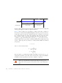
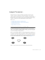
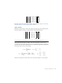
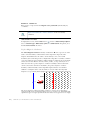
Importing ECAD Files
In this section:
• Overview of the ECAD Import
• Importing ODB++(X) Files
• Importing GDS-II Files
• Importing NETEX-G Files
• ECAD Import Options
• Meshing an Imported Geometry
• Troubleshooting ECAD Import
Overview of the ECAD Import
This section explains how to import ECAD files into COMSOL Multiphysics. An
ECAD file can, for example, be a 2D layout of a printed circuit board (PCB) that is
imported and converted to a 3D geometry.
EXTRUDING LAYERS
A PCB layout file holds information about all traces in several 2D drawings or layers.
During import, each 2D layer is extruded to a 3D object so that all traces get a valid
thickness. A standard extrude operation requires that the source plane is identical to
the destination plane. This makes it impossible to extrude an entire PCB with several
layers, where the source and destination planes in almost all cases do not match. It is
possible to do several extrude operations, one for each layer. For complex PCBs it is
not easy to put these layers together, and it might take a very long time to go from the
Geometry node to the Material node or a physics interface node in the Model Builder.
In some situations this operation might fail.
As a result of these performance issues, the ECAD Import has its own extrude
operation that automatically connects non matching planes. In one operation this
functionality extrudes and connects all layers, so there is only one geometry object
after the import. With only one object, it is easy to switch to the physics modes. Use
this special extrude operation when using the grouping option All.
98 |
CHAPTER 3: MODELING WITH THE AC/DC MODULE