1
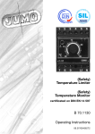
(Safety)
Temperature limiter
(Safety)
Temperature monitor
to DIN 3440
B 70.1130
Operating Instructions
Version 1 / 8.98 / 00354358
Conformance symbol
The instrument conforms with the requirements of
DIN 3440.
H
If any servicing is required, the instrument must be
returned to the main factory.
In accordance with the recommendations of
Germanische Lloyd, specific applications require
the availability of a replacement instrument.
1
B
Please read these Operating Instructions before
commissioning the instrument. Keep the operating
instructions in a place which is accessible to all
users at all times.
Please assist us to improve these operating
instructions, where necessary.
We are always grateful for your suggestions.
Phone in Germany
from abroad
Fax
in Germany
from abroad
H
(06 61) 6003-727
(+49)661 6003-0
(06 61) 60 03-5 08
(+49) 661 6003-607
Should any difficulties arise during start-up, you are
asked not to carry out any unauthorised manipulations on the instrument. You could endanger
your rights under the warranty!
Please contact the nearest JUMO office or the main
factory.
2
x
3
Contents
1
Introduction
1.1
1.2
1.3
1.4
Description ..........................................................................5
Block structure ....................................................................6
Type designation ................................................................7
Registration number ...........................................................8
2
Installation
2.1
2.2
2.3
2.4
Location and climatic conditions ........................................9
Dimensions .........................................................................9
Mounting on a standard rail
or a mounting plate ...........................................................10
Removal ............................................................................11
3
Electrical connection
3.1
3.2
3.3
Installation notes ...............................................................12
Connection diagram .........................................................13
Lead compensation ..........................................................14
4
Function
4.1
4.2
4.3
Indication and controls .....................................................15
O-function .........................................................................16
S-function .........................................................................17
5
Starting up
6
Functional test
6.1
6.2
Test frequency ..................................................................19
Testing STBs and STWs with O-function
when thermocouples are connected ................................20
Testing STBs and STWs with S-function
when thermocouples are connected ................................22
Testing STBs and STWs with O- or
S-function when connecting resistance thermometers ....25
6.3
6.4
7
Test in the event of a fault
8
Technical data
x
1 Introduction
1.1
Description
The areas of application for (safety) temperature limiters or monitors
((S)TB or (S)TW) are to be found wherever thermal processes have
to be monitored, and where the system must be set to a safe operating condition in the event of a fault. If the permitted temperature
limit is reached, or a fault occurs within the permitted temperature
range (probe break/short-circuit, component defect, power failure),
then the instrument switches off without delay. If the fault is no
longer present, then TB and STB must be reset manually. This can
be done by means of a reset pushbutton on the instrument, or by an
external reset button. The flow of energy is only enabled again when
the temperature is lower (O-function) or higher (S-function) than the
preset limit temperature by the amount of the switching differential.
In the event of a short-term power failure (≤ 1min) within the satisfactory range of the system, the instrument is enabled automatically
after the power has been restored. The amount of the switching differential is 3°C, 10°C, 30°C or 100°C.
The analogue limit setting knob for the limit temperature is mounted
on the front panel. An unintentional or unauthorised adjustment of
the limit setting is prevented by a clear cover which can be leadsealed. The instruments are intended for use as built-in units for fixing onto standard rails to EN 50022-35. The screw terminals for the
electrical connection (max. conductor cross-section 2.5mm2) are on
one wiring level.
The instruments function over defined temperature ranges between
0 and 2000 °C.
Temperature monitor TW*
Temperature monitors are devices which, after cutting out, are automatically reset when the probe temperature has fallen below the
preset limit value by the amount of the switching differential.
Safety temperature monitor STW*
Safety temperature monitors are temperature monitors which, in
addition, meet the requirements for enhanced safety to DIN 3440.
5
1 Introduction
Temperature limiter TB*
Temperature limiters are devices which are locked out after cutting
out. They can be reset, either manually or by means of a tool, when
the probe temperature has fallen below the limit value by the
amount of the switching differential.
Safety temperature limiter STB*
Safety temperature limiters are temperature limiters which, in addition, comply with the requirements for enhanced safety according
to DIN 3440.
* Extract from DIN 3440
1.2
Block structure
6
1 Introduction
1.3
Type designation
(1)
701130 /
****
(2)
–
***
(3)
–
**
(4)
/
***
(1) Basic type extensions
0151
Temperature monitor with O-function
0152
Temperature monitor with S-function
0153
Temperature limiter with O-function
0154
Temperature limiter with S-function
0251
Safety temperature monitor with O-function
0252
Safety temperature monitor with S-function
0253
Safety temperature limiter with O-function
0254
Safety temperature limiter with S-function
(2) Measurement inputs
001
Resistance thermometer Pt100
in 2-wire circuit
037
W3Re-W25Re
042
Fe-Con L
043
NiCr-Ni K
044
Pt10Rh-Pt S
046
Pt30Rh-Pt6Rh B
7
1 Introduction
(3) Supply
02
230V AC, +10% / -15% 48—63Hz
05
08
115V AC, +10% / -15% 48—63Hz
24V AC, +10% / -15% 48—63Hz
(4) Extra Codes
202
205
Switching differential 3°C (only for Pt100)
Switching differential 10°C
206
Switching differential 30°C
208
229
Switching differential 100°C
231
Lead resistance 10Ω internally compensated*
233
Lead resistance 30Ω internally compensated*
235
Lead resistance 50Ω internally compensated*
Internal reset button (extra Code with TB only)
GL
245
062
Lead resistance 1Ω internally compensated*
* Lead compensation resistor LAW (10Ω) is included in the delivery
Accessories
External reset button RT
Sales No. 70/97097865
Mounting plate BS
Sales No. 70/00059172
Lead compensation resistor LAW (10Ω)
Sales No. 70/00322800
1.4
Registration number
For Type 701130/... : TB/TW/STB/STW 1091 97
8
2 Installation
2.1
Location and climatic conditions
The location and the climatic conditions must meet the
requirements defined in the specifications under Technical Data.
(v Chapter 8).
2.2
Dimensions
9
2 Installation
2.3
Mounting on a standard rail
or a mounting plate
The instruments are designed as built-in units and are protected to
IP20 as standard.
h Insert the instrument from above into the standard rail or into the
cut-out of the mounting plate and swing it down until it snaps
into position Mounting the GL-version:
h Push the fixing elements into the guides on the sides
h Insert the unit from above into the rail and swing it down until it
snaps into position (as above)
h Push the fixing elements up to the rail and tighten them evenly
with a spanner.
(see diagram on next page!)
10
2 Installation
2.4
Removal
h Insert a screwdriver in the direction of the arrow under the clip h Press the clip down and swing the unit up at the same time 11
3 Electrical connection
3.1
Installation notes
■ The requirements of VDE 0100 “Regulations for the installation
of power equipment with rated voltages up to 1000V” or the
equivalent national regulations must be observed in the choice
of cable material, the installation and the electrical connection of
the equipment.
■ The electrical connection must only be made by properly
qualified personnel.
■ Isolate the instrument on both poles from the supply if there may
be contact with live parts during work.
■ The electromagnetic compatibility (EMC) conforms to the
standards and regulations listed under Technical Data.
v Chapter 8
■ Sensor, output or supply cables should be routed separately
from one another, and not laid in parallel.
■ Sensor cables must be twisted and shielded. Avoid running
them close to current-carrying components or cables.
■ Do not connect any additional loads to the supply terminals of
the instrument.
■ The instrument is not suitable for installation in hazardous areas.
■ Inductive components in the neighbourhood of the instrument,
such as contactors or solenoid valves, must have RC
combinations fitted for interference suppression.
■ The approval of the instrument to DIN 3440 is only valid if the
temperature probes marked with * in Chapter 8 “Technical Data“
are used.
If temperature probes are used which are not marked or listed,
then the approval of the instrument and probes must be
checked.
12
3 Electrical connection
3.2
Connection diagram
The electrical connection
must only be carried out by
qualified personnel.
Connection for
Terminals
Relay output
7
8
9
common
n.o. (make)
n.c. (break)
Supply
as on label
L1
N
line
neutral
External reset
pushbutton
5
6
Resistance
thermometer in
2-wire circuit
1
2
LAW= Lead compensation
resistor
Thermocouple
1
2
3
4
230V 2A,
resistive load
– Thermocouple 1
+
– Thermocouple 2
+
13
3 Electrical connection
3.3
Lead compensation
A lead resistance of 0.5Ω is allowed for internally as standard;
1Ω,10Ω, 30Ω or 50Ω (extra Code) to special order.
A lead compensation resistor LAW (10 Ω; included in the delivery
package when the appropriate extra Code is ordered) is required for
the connection to Pt 100 resistance thermometers with a max.
operating temperature of 700°C.
Compensation condition: RL = Rcomp + RLF
RL
internally compensated lead resistance of the
measuring circuit
Rcomp resistance of the lead compensation resistor LAW
resistance of the probe leads
RLF
14
4 Function
4.1
Indication and controls
Screw terminals, max. 2.5mm2
Reset button (extra Code with TB only)
Limit setting knob
Limit scale
Fault indicator for channel 1 (S1) and channel 2 (S2)
S2 only for STB and STW
Lead-sealable clear cover
Plastic casing
15
4 Function
4.2
O-function
Response in normal operation
– ϑ < ϑG
– temperature rises
⇒ the relay drops out at ϑ = ϑG .
Response after rising above the limit
– ϑ > ϑG
– temperature falls
⇒ the relay pulls in automatically at ϑ = ϑG–Xsd (STW and TW),
or has to be reset manually (STB and TB)
Response in fault condition
In the event of a fault (probe break/short-circuit, faulty
electronics, supply failure) the relay drops out.
When
– the fault has been cleared
– ϑ ≤ ϑG–Xsd
⇒ then the relay pulls in automatically (STW and TW).
STB and TB must be reset manually. Only in the event of a
short-term power failure (≤ 1 min) in the satisfactory range of
the system, will the instrument automatically be enabled after
the power has been restored.
16
4 Function
4.3
S-function
Response in normal operation
– ϑ > ϑG
– temperature falls
⇒ the relay drops out at ϑ = ϑG .
Response after falling below the limit
– ϑ < ϑG
– temperature rises
⇒ the relay pulls in automatically at ϑ= ϑG+Xsd (STW and TW),
or has to be reset manually (STB and TB)
Response in fault condition
In the event of a fault (probe break/short-circuit, faulty
electronics, supply failure) the relay drops out.
When
– the fault has been cleared
– ϑ≥ϑG+Xsd
⇒ then the relay pulls in automatically (STW and TW).
STB and TB must be reset manually. Only in the event of a
short-term power failure (≤ 1 min) in the satisfactory range of
the system, will the instrument automatically be enabled
after the power has been restored.
17
5 Starting up
The setting of the limit value
must not change by itself under
operating conditions. A clear
cover which is lead-sealable
is therefore provided to prevent
unintentional or unauthorised
adjustment.
h Swing the clear cover upwards and remove it.
h Set the required limit on the scale using the limit setting knob.
The limit setting can easily be read, even when the clear cover is
in position. The start and end of the range are fixed by stops.
h After setting the limit, carry out the function test (v Chapter 6)
and lead-seal the clear cover.
H
The safety circuit must be reset after every switch-on or
break in the mains supply, by using the internal or external reset button (only for TB and STB).
Only in the event of a short-term power failure (≤ 1 min)
in the satisfactory range of the installation, will the
instrument automatically be enabled after the power has
been restored.
For lead sealing, a hole is provided on each side of the clear
cover. A wire is passed through
these holes to connect the
cover and the casing. The wire
ends are secured by a lead
seal.
18
6 Functional test
6.1
Test frequency
The safety temperature monitors and limiters fulfil the requirements
made in Draft DIN 3440 A1 of September 1991.
In addition, the instrument must undergo an annual functional test.
H
Generally, the functional test always starts from the satisfactory range of the system, i.e. the fault signal diodes
must not be lit up and the STBs must be reset.
It is necessary to short-circuit or open the measurement input circuit(s) for the functional test. The reset button must also be shortcircuited during the test.
For a rapid functional test it is therefore recommended that the buttons I, II, and III are included in the measurement or reset circuits.
H
When connecting themocouples and buttons it is important to ensure that no additional thermal e.m.f occurs
(temperature differences at the terminals).
When resistance thermometers and buttons are connected, it must be ensured that the contact resistance is
not too high. (0.4Ω ≈ 1°C error).
.
Carry out a functional test after every malfunction!
19
6 Functional test
6.2
Testing STBs and STWs with O-function
when thermocouples are connected
✱ Short-circuit the reset button
✱ Simulate a probe break of thermocouple 1:
The LEDs S1 and S2 must light up.
The external fault indicator must light up. The safety circuit
must be opened.
The LEDs S1 and S2 must go out after about 5 sec.
The external fault indicator remains lit up and the safety circuit remains open.
20
6 Functional test
✱ Remove the short-circuit across the reset button:
The LEDs S1 and S2 light up again.
The external fault indicator remains on.
✱ Remove the probe break:
If the probe temperature is within the permitted temperature
range i.e. below the limit setting by the switching differential,
then the two LED S1 and S2 must go out after approx. 5 sec.
For an STW, the external fault indication must also disappear
and the safety circuit must close.
For an STB, the external fault indication must continue to be
lit up and the safety circuit must remain open. The safety circuit is only closed again when the reset button is pressed.
✱ Repeat the procedure for thermocouple 2.
Check response on power failure (STB).
In the satisfactory range of the system:
✱ Switch off mains:
Wait for approx. 1 min
✱ Switch on mains:
The LEDs S1 and S2 must light up for approx. 5 sec and then
go out
The external fault indicator must go out after a further 2 sec
approx. and the safety circuit must close automatically.
In the event of a fault:
✱ Simulate a probe break of the thermocouple 1:
The LEDs S1 and S2 must light up.
✱ Remove the probe break of thermocouple 1:
The LEDs S1 and S2 must go out after about 5 sec.
The safety circuit remains open.
21
6 Functional test
✱ Switch off mains for at least 5 sec.
✱ Switch on mains:
The LEDs S1 and S2 must light up for about 5 sec and then
go out.
The external fault indication continues to be lit up and the
safety circuit remains open. The safety circuit will only close
again, and the external fault indication will go out, when the
reset button is pressed.
6.3
Testing STBs and STWs with S-function
when thermocouples are connected
22
6 Functional test
✱ Short-circuit the reset button
✱ Simulate a probe short-circuit of thermocouple 1:
The LEDs S1 and S2 must light up.
The external fault indication must light up. The safety circuit
must be open.
LEDs S1 and S2 must go out after approx. 5 sec.
The external fault indication remains lit and the safety circuit
remains open.
✱ Remove short-circuit of reset button:
The LEDs S1 and S2 light up again.
The external fault indication remains on.
✱ Remove probe short-circuit:
If the probe temperature is within the permitted temperature
range, i.e. above the limit setting by the switching differential,
then the two LEDs S1 and S2 must go out after approx. 5
sec.
For an STW, the external fault indication must also disappear
and the safety circuit must close.
For an STB, the external fault indication must continue to be
lit up and the safety circuit must remain open. It will only
close again when then reset button is pressed.
✱ Repeat the procedure for thermocouple 2.
Check the response after power failure (STB only)
In the satisfactory range of the system:
✱ Switch off mains:
Wait for approx. 1 min
✱ Switch on mains:
The LEDs S1 and S2 must light up for approx. 5 sec and then
go out.
23
6 Functional test
The external fault indication must go out after a further 2 sec
(approx.) and the safety circuit must close automatically.
In the event of a fault:
✱ Simulate a probe short-circuit of thermocouple 1:
The LEDs S1 and S2 must light up.
✱ Remove the probe short-circuit of thermocouple 1
The LEDs S1 and S2 must go out after approx. 5 sec.
The safety circuit remains open.
✱ Switch off mains for at least 5 sec
✱ Switch on mains:
The LEDs S1 and S2 must light up for approx. 5 sec and then
go out.
The external fault indication continues to be lit up and the
safety circuit remains open. Only when the reset button is
pressed, will the safety circuit close and the external fault
indication go out.
24
6 Functional test
6.4
Testing STBs and STWs with O- or
S-function when connecting resistance
thermometers
✱ Short-circuit the reset button
✱ Simulate a probe break:
The LEDs S1 and S2 must light up.
The external fault indication must light up. The safety circuit
must be open.
The LEDs S1 and S2 must go out after approx. 5 sec.
25
6 Functional test
The external fault indication continues to be lit up and the
safety circuit remains open.
✱ Remove the short-circuit across the reset button:
The LEDs S1 and S2 light up again.
The external fault indication remains on.
✱ Remove the probe break:
If the probe temperature is within the permitted temperature
range (i.e. below the limit setting by the switching differential
for an O-function, or above the limit setting by the switching
differential for an S-function), then the two LEDS S1 and S2
go out after approx. 5 sec.
For an STW, the external fault indication must also go out and
the safety circuit must close.
✱ For an STB, the external fault indication must continue to be lit
up and the safety circuit must remain open. The safety circuit will
only close again when the reset button is pressed.
✱ Short-circuit the reset button
✱ Simulate a probe short-circuit:
The LEDs S1 and S2 must light up.
The LEDs S1 and S2 must go out after approx. 5 sec.
✱ Remove short-circuit across the external reset button:
The LEDs S1 and S2 light up again.
✱ Remove the probe short-circuit:
If the probe temperature is within the permitted temperature
range (i.e. below the limit setting by the switching differential
for an O-function, or above the limit setting by the switching
differential for an S-function), then the two LEDs S1 and S2
must go out after approx. 5 sec.
For an STW, the external fault indication must go out and the
safety circuit must close.
26
6 Functional test
For an STB, the external fault indication must continue to be
lit up and the safety circuit must remain open. It is only closed
again when the reset button is pressed.
Check response after a power failure (STB)
In the satisfactory range of the system:
✱ Switch off mains:
Wait approx. 1 min
✱ Switch on mains:
The LEDs S1 and S2 must light up for approx. 5 sec and then
go out.
The external fault indication must go out after (approx.) a further 2 sec and the safety circuit must close automatically.
In the event of a fault:
✱ Simulate a probe break:
The LEDs S1 and S2 must light up.
✱ Remove the probe break:
The LEDs S1 and S2 must go out after approx. 5 sec
The safety circuit remains open.
✱ Switch off mains for at least 5 sec
✱ Switch on mains:
The LEDs S1 and S2 must light up for approx. 5 sec and then
go out.
The external fault indication continues to be lit up and the
safety circuit remains open. Only when the reset button is
pressed, will the safety circuit close and the external fault
indication go out.
27
7 Test in the event of a fault
In the event of a system fault, the instrument switches off the system. This condition is indicated by LED S1 lighting up (S1 and S2
on instruments with enhanced safety). The fault is signalled simultaneously by the external fault indication. In this condition, the relay of
the temperature limiting device (STB, TB, STW, TW) is not operated.
Initial condition: STB has switched off the system.
Fault indicators are lit
Fault indicators are off
The fault is still present in the
system
(over/undertemperature, probe
break/short-circuit)
h Press the reset button (at
least 5 sec) until S1 and S2
go out
If the safety circuit remains
open, the system and the
probe circuit have to be
checked.
h Press the reset button
If the instrument remains inhibited after pressing the reset
button, the replacement instrument must be installed and the
functional test carried out.
28
8 Technical data
Inputs
Resistance thermometer
Pt100 in 2-wire circuit:
0—120°C*
0—300°C*
0—400°C*
0—600°C*
200—500°C*
Ambient temperature error: 0.8°C/10°C
Lead compensation:
A lead resistance of 0.5Ω is allowed for internally as standard;
1Ω, 10Ω, 30Ω or 50Ω on request. A lead compensation resistor
LAW (10Ω) is required for connection to resistance thermometers
with a max. operating temperature of 700°C.
Double thermocouples
NiCr-Ni K:
200— 600°C*
400— 800°C*
600—1000°C*
800—1200°C
Pt10Rh-Pt S:
400— 800°C*
800—1200°C*
1000—1400°C
1200—1600°C
Pt30Rh-Pt6Rh B:
800—1200°C*
1000—1400°C*
1200—1600°C
1400—1800°C
Fe-Con L:
50— 450°C*
200— 600°C*
500— 900°C
W3Re-W25Re:
1600— 2000°C
Ambient temperature error: 2.0°C/10°C
* For temperature probes used in accordance with DIN 3440, the
max. limit temperature of the instrument is determined by the
upper meas. temperature of the selected temperature probe.
29
8 Technical data
Outputs
Relay
with floating changeover contact
Switching capacity:
2 A 230 V AC, resistive load
protected by fuse 2A M
Contact life: 100.000 switching operations at rated load
General data
Switching point accuracy
±2% of span
Switching differential
3°C (for Pt100 only),
10°C, 30°C or 100°C
Supply
230V AC,
115V AC,
24V AC,
+10% / -15% 48—63Hz
+10% / -15% 48—63Hz
+10% / -15% 48—63Hz
Power consumption
4 VA approx.
Permissable ambient temperature
0 to +55 °C
Permissable storage temperature
–40 to +80 °C
Climatic conditions
rel. humidity 75% max., no condensation
Protection
IP20 (to EN 60529)
Electrical safety
to EN 60730-1 ’96
creepage distances:
mains to electronics and probe
mains to relay
relay to electronics and probe
≥ 8mm
≥ 3mm
≥ 8mm
Instrument can be connected to SELV circuits.
30
8 Technical data
Test voltages
to EN 60730-1 ’96 Tab. 13.2
Electromagnetic compatibility
to EN 50081-1, EN 50082-2
Ambient conditions
to EN 60730-1 ’96 Para. 2.12.6
“normal”
Operating conditions
The instrument is designed as a built-in device according to:
- VDE 0160 5.5.1.3 5/88
- VDE 0106 Part 100 3/83
Operating position
unrestricted
Weight
250g approx.
Dimensions (WxHxD)
54mm x 70mm x 110mm
Casing
Plastic
Combustibility class V0
With extra Code “GL”
The instrument meets Application Category C
according to the GL-guideline.
Temperature:
Rel. humidity:
Vibration:
0 to 55°C
not exceeding 100% r.H.
not exceeding 0.7g
Standard accessories
- Operating Instructions B 70.1130
- 2 fixing elements (only for GL-version)
- LAW (only with extra Code 229, 231, 233, 235)
31
M.K. JUCHHEIM GmbH & Co.
36035 Fulda
Germany
Phone ++49 6 61-60 03-0
Fax
++49 6 61-60 03-6 07
Telex 49 701 juf d
email [email protected]
United Kingdom
JUMO Instrument Co. Ltd.
Temple Bank, Riverway
GB-Harlow,
Essex CM20 2TT
Phone (0 12 79) 63 55 33
Fax
(0 12 79) 63 52 62
USA
JUMO PROCESS CONTROL INC.
735 Fox Chase,
Coatesville, PA 19320
Phone 610-380-8002,
800-554 JUMO
Fax
610-380-8009