1
INSTALLATION / OPERATION
EAN-1350
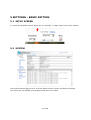
1.3 Megapixel Day-/Night Network Camera
with Progressive Scan CCD Technology
Safety warnings
To avoid any damage, please consider the following safety warnings:
Never place the recorder near to heaters, furnaces, other heat sources or under direct solar irradiation.
Operate the device only in locations providing the tolerable operating temperature range 0°C~40°C.
Make sure that the device‘s ventilation slots are not covered or sheeted.
For cleaning, make sure the device is plugged off and only use a damp cloth without acid detergent.
Install the device only in dry and dustproof surroundings. Protect the device against any liquid‘s penetration.
Avoid the penetration of any artefacts.
Do not open the recorder yourself. In case of malfunction, contact your local installer or dealer. Unauthorized
opening of the device will annul the warranty claim!
Avoid any affection of the device through vibrations or mechanical shock at the recorder‘s installation location.
.
ATTENTION! This is a class A product which may cause radio interference in a domestic environment;
in this case, the user may be urged to take adequate measures.
This equipment has been tested and found to comply to part 15 of the FCC Rules. These limits
are designed to provide reasonable protection against harmfulinterference in a residential
installation. This equipment generates, uses and can radiate radio frequency energy and, if not
installed and used in accordance with the instructions, may cause harmful interference to radio
communications. However, there is no guarantee that interference will not occur in a particular
installation. If this equipment does cause harmful interference to radio or television reception,
which can be determined by turning the equipment off and on, the user is encouraged to try to
correct the interference by one or more of the following measures:
• Reorient or relocate the receiving antenna.
• Increase the separation between the equipment andreceiver.
• Connect the equipment into an outlet on a circuit different from that to which the receiver is
connected.
• Consult the dealer or an experienced radio/ TV technician for help.
This Product is RoHS compliant.
WEEE
Your EverFocus product is designed and manufactured
with high quality materials and components which can
be recycled and reused.
This symbol means that electrical and electronic
equipment, at their end-of-life, should be disposed of
separately from your household waste.
Please, dispose of this equipment at your local
community waste collection/recycling centre.
In the European Union there are separate collection
systems for used electrical and electronic product.
Please, help us to conserve the environment we live in!
Ihr EverFocus Produkt wurde entwickelt und
hergestellt mit qualitativ hochwertigen Materialien
und Komponenten, die recycelt und wieder
verwendet werden können.
Dieses Symbol bedeutet, dass elektrische und
elektronische Geräte am Ende ihrer Nutzungsdauer
vom Hausmüll getrennt entsorgt werden sollen.
Bitte entsorgen Sie dieses Gerät bei Ihrer örtlichen
kommunalen Sammelstelle oder im Recycling
Centre.
Helfen Sie uns bitte, die Umwelt zu erhalten, in der
wir leben.!
The information in this manual was current upon publication. The manufacturer reserves the right to revise and
improve his products. Therefore, all specifications are subject to change without prior notice. Misprints reserved.
Please read this manual carefully before installing and using this unit. Be sure to keep it handy for later reference.
2 of 59
TABLE OF CONTENTS
1 Introduction ....................................................................................................... 5
1.1
Features ..................................................................................................5
1.2
DELIVERY SCOPE......................................................................................5
1.3
System requirements ................................................................................6
1.4
Specifications ...........................................................................................6
2 Hardware INSTALLATION ................................................................................... 8
2.1
Backpanel Connectors ...............................................................................8
2.2
Lens mounting .......................................................................................10
2.3
Camera mounting ...................................................................................11
2.4
Video Installation for camera / lens adjustment...........................................11
2.5
Alarm IN- / Out installation ......................................................................12
2.5.1 Terminal pin assignment: ..........................................................................12
2.5.2 Alarm Inputs............................................................................................12
2.5.3 Alarm Output ...........................................................................................13
2.6
Audio Installation....................................................................................14
2.7
RS-485 telemetry installation ...................................................................14
2.8
Network Installation / Wiring ...................................................................15
2.9
Power input connection............................................................................15
3 IP- setup .......................................................................................................... 16
3.1
Network Installation / Basic IP - Setup with IP-Finder...................................16
3.2
Network Installation / Router settings ........................................................16
3.3
Network Installation / Browser setup .........................................................17
3.4
Active X - installation at first time login......................................................17
4 Main operation screen ...................................................................................... 19
5 Settings - Basic setting..................................................................................... 20
5.1
Setup screen..........................................................................................20
5.2
System .................................................................................................20
5.2.1 System Log .............................................................................................21
5.3
Video / Image ........................................................................................22
5.3.1 Video ......................................................................................................22
5.3.2 PreProc ...................................................................................................23
5.3.3 Sensor ....................................................................................................24
5.4
Audio ....................................................................................................26
5.5
PTZ.......................................................................................................27
5.6
User......................................................................................................28
5.7
Network ................................................................................................31
5.7.1 Network ..................................................................................................31
5.7.2 Services ..................................................................................................32
5.7.3 Streaming ...............................................................................................32
5.7.4 PPPoE .....................................................................................................33
5.7.5 DDNS .....................................................................................................34
5.7.6 UPnP ......................................................................................................35
5.7.7 SMTP ......................................................................................................37
5.7.8 SAMBA....................................................................................................38
5.7.9 Notification ..............................................................................................39
5.7.10 Multicast................................................................................................40
5.7.11 Date / Time ...........................................................................................41
5.7.12 IP Filtering.............................................................................................42
6 SETTINGS - Application Setting ........................................................................ 43
6.1
Event ....................................................................................................43
6.1.1 Event......................................................................................................43
6.1.2 Trigger....................................................................................................46
3 of 59
6.1.3 Event Server............................................................................................47
6.2
Motion Detection.....................................................................................48
6.3
Firmware Upgrade ..................................................................................49
6.4
Factory Default.......................................................................................50
6.5
Reboot ..................................................................................................51
7 Operation ......................................................................................................... 52
7.1
Main screen controls................................................................................52
7.2
General and Video settings.......................................................................52
7.3
Event Alerts ...........................................................................................53
7.4
Pan / Tilt / Zoom ....................................................................................54
7.5
Record / Snapshot setting ........................................................................55
7.6
Manual record ........................................................................................56
7.7
Manual Snapshot ....................................................................................56
7.8
Audio ....................................................................................................57
7.9
Full Screen mode ....................................................................................57
8 Attachment A: Alarm Interface Circuit .............................................................. 58
4 of 59
1 INTRODUCTION
1.1 FEATURES
•
•
•
•
•
•
•
•
1.3 Megapixel Progressive Scan CCD sensor providing high definition video
Progressive Scan technology for clear reproduction of fast moving objects
Highest Sensitivity Day/Night Mode with Auto-IR Cut Filter removal technologies and
CCD sensor
With digital pan/tilt and electronic zoom, users can point and see the very details of the
region of interest
Dual codec (MPEG4/MJPEG) simultaneously
2-way duplex audio
C/CS mount DC - lens exchangeable with backfocus adjustment
Power over Ethernet (PoE) eases installation, security , and maintenance.
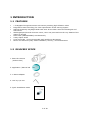
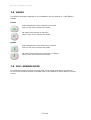
1.2 DELIVERY SCOPE
1. EAN-130 camera
(without lens)
2. Application / Manual CD
3. C-Mount adapter
4. Hex key 0,9 mm
5. Quick Installation Guide
5 of 59
1.3 SYSTEM REQUIREMENTS
Network environment
LAN 10/100 Ethernet Cable CAT.5E or higher
Monitoring system requirements
Operating system
Browser
Windows 2000 Professional SP4/
XP SP2 / VISTA
Internet Explorer 6.x or later versions
System hardware
CPU:
RAM:
VGA resolution:
DirectX Version:
Pentium 4, 2.4GHz or better
512MB (1GB recommended)
1024x768 or higher
DirectX 9.0c
1.4 SPECIFICATIONS
Camera
Sensor Type
Effective Pixels
Electronic Shutter
Digital Slow Shutter
AGC (Auto gain control)
AWB (Auto white balance)
IR-Cutfilter
Lens Mount
Minimum Illumination
Analog Video Out
Video Output
Network Streaming
Video Compression
Video Frame Rate
Compression Rate
Video Resolution
Pan/Tilt
Motion Detection
Video Streaming
Protocols
OSD
1/3 progressive scan CCD
1280x960
1:50 ~ 1:10.000
2x ~ 32x max / Off
3 level
Auto, Manual, Indoor, Outdoor
automatic / manual / ext. contact mode
CS-mount/C-mount DC-drive, backfocus adjustment
1 Lux / F 1,2 color mode
0,2 Lux / F1,2 b/w mode
Composite PAL 1 VSS, BNC (switchable between Videoout and IP streaming)
MPEG4 / JPEG (dual streaming)
12, 5 IPS max (JPEG 1260x980)
25 IPS max ( MPEG4 640x480)
Configurable
5 level
MPEG4: 640x480, 352x288, 320x240, 176 x 144
MJPEG: 1260x960, 640x480, 352x288, 320x240, 176 x
144
digital and support for RS-485 PT devices (Pelco-D / P)
3 zones + 1 exclusive zone
RTSP/RTP/UDP ,RTSP/RTP/TCP,
RTSP/RTP HTTP Tunnel ,LAN Multicast
Text, Time, and Date configurable (except MJPG
1280x960)
6 of 59
Audio
Audio modes
Audio Codec
Communication
LAN Port
Communication Protocol
Alarm
RS485
Status LED
Power
Dimensions
Operating temperature
Storage temperature
Humidity
Software
Browser
Application Software
OS supported
1 x line in, 1 x line out, 3,5 mm stereo sockets
duplex / full duplex / simplex
G.711, G.726 selectable
RJ-45 10/100M auto-sensed, auto crossover
HTTP, RTSP, FTP, SMTP, TCP/IP, UDP, ARP, ICMP, DHCP,
PPPoE, DDNS, UPnP, SAMBA
2x input, 1 relay output, screwless terminal
1 x RS-485 telemetry out (Pelco-D/P), screwless terminal
3x: Status, network link / traffic
12V DC/ 24V AC, 8W max.
or PoE 802.3af
166 mm(L) x 80mm(W) x 81mm(H) (w.o. sockets / lens)
0°C ~ 55°C
-20°C ~ 70°C
10% ~ 95% non-condensing
Integrated browser applet (Internet Explorer 6.0 or
above required)
PowerCon 4.3 or higher (optional)
EverFocus NVR series
Microsoft Windows XP, Vista
Software Features / Functions
TCP/IP
User management
Date/ Time
Event management
Event schedule
Event reaction
Motion
Pre-Alarm-Buffer
Display
Video settings
Others
Static IP Address / DHCP, PPPoE, DDNS, UPnP, SAMBA
Multicast, SMTP (Event notification), IP filtering, Primary
/Secondary DNS Server
3 level user rights, anonymous login
Time / Date overlay
internal RTC or sychr. by NTP or PC-time
3 redundant NTP server
Event trigger Motion, Alarm In, Boot
Weekly schedule with 1 timezone per weekday
Record to FTP / Samba, E-Mail notification, HTTP / TCP notification, Relay output
3 zones with adjustable sensitivity and
treshold
up to 10 s
Overlay time/date/text
Image normal, flip h/v, rotate 180°
Digital Zoom 100%~800% (client browser) 100~1200%
(camera)
Brightness, Saturation, Contrast, Sharpness, Backlight,
Remote firmware upgrade, Remote reboot, Configuration
up- / download
7 of 59
2 HARDWARE INSTALLATION
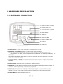
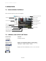
2.1 BACKPANEL CONNECTORS
1. Power 12 VDC / 24 VAC
2. Switch Video / IP
3. Terminal Alarm / RS485
4. Reset Switch
5. LAN port
6. Video out BNC
7. Power / Status LED
8. Audio in
9. Audio out
1. Power input: 12 V DC / 24 V AC input, no polarity for 12 V DC
2. Switch IP / TV Teset: Network or Video mode work alternative
For lens and camera adjustment connect a video monitor to the BNC socket, turn
the switch to "TV Test", then turn OFF and turn ON power (no network streaming
this mode)
For network streaming switch back to "IP Cam" and OFF and turn ON power (no BNC
video out in "IP Cam" mode.
in
3. Terminal Alarm / RS485: Screwless terminal for alarm inputs / outputs and RS-485
interface.
4. Reset switch: Complete reset of camera to default settings
5. LAN-Port: 10/100 Mbit Lan Interface, RJ45 socket with autosensing function (Patch - or
crossover cables supported), PoE powering supported
6. Video out: BNC socket for composite video output signal 1 V pp. If switch (2) is in
position "TV test", this output can be used for adjusting lens and camera position.
7. Power LED: Red light indicates power on.
8 of 59
8. Audio Input: 3,5 mm audio socket for Audio line input 1 V max / 10 KOhm
9. Audio Output: 3,5 mm audio socket for Audio line output 1 V max to 10 KOhm
9 of 59
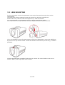
2.2 LENS MOUNTING
For lens mounting, remove the protection cover at the front and screw the lens on the
camera body.
The EAN-1350 camera supports lenses with manual iris and DC-controlled iris.
Please make sure, that the used lens supports 1/3" CCD chip format.
It is recommanded to use Megapixel lenses to achieve best image quality.
If a C-Mount lens is used, mount the C-Mount adapter between camera and lens.
If it is not possible to get a focussed image by lens focus adjustment, correct the backfocus
by the lever on top of the camera. Unlock the fixation screw first by the hex key (in camera
package).
If a DC-controlled lens is installed, make sure to connect the control cable to the DC iris
socket ("IRIS") at the right side of the camera.
10 of 59
2.3 CAMERA MOUNTING
The camera monting adapter allows using standard camera brackets with 1/4" thread.
The mounting adapter can be mounted at top or botton side of the camera body.
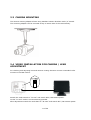
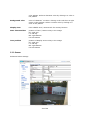
2.4 VIDEO INSTALLATION FOR CAMERA / LENS
ADJUSTMENT
For checking and adjusting lens and camera viewing direction connect a standard video
monitor to the BNC socket.
Switch the mode switch to "TV test" and switch OFF / ON camera power.
In this "TV test" mode is no IP streaming possible.
After adjustment switch the mode back to "IP Cam" and switch OFF / ON camera power.
11 of 59
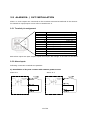
2.5 ALARM IN- / OUT INSTALLATION
Alarm- in- and outputs are connected to the screwless terminal at backside of the camera.
For Details to input/output circuit refer to Attachment A.
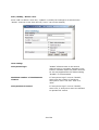
2.5.1 Terminal pin assignment:
Contact
Description
1
2
3
4
5
6
7
8
9
10
11
Alarm IN 1 + (max 50 V DC)
Alarm IN 1 Alarm IN 2 + (max 50 V DC)
Alarm IN 2 Relay COM (max. 24 V DC / 1 A)
Relay N.C. (max. 24 V DC / 1 A)
Relay N.O. (max. 24 V DC / 1 A)
RS-485+
RS-485+ 3,3 VDC Output
GND
Both alarm inputs are opto-coupler inputs and require DC Voltage 3~50 VDC for activation.
2.5.2 Alarm Inputs
Following connection methods are possible:
A) Installation of dry N.O. contact with camera power source
Alarm In 1
Alarm In 2
12 of 59
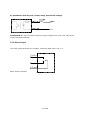
B) Installation with dry N.O. contact using external DC voltage
ATTENTION: Do not exceed the maximum input voltage of 50 V DC. This may cause
serious hardware damage.
2.5.3 Alarm Output
The relay output provides dry contacts, maximum load is 24 V DC, 1 A.
7 (N.O.)
5 (Com)
Relay output contacts:
13 of 59
2.6 AUDIO INSTALLATION
Audio input and output are connected to the 3,5mm sockets.
Please make sure to use a pre-amplified microphone with line level 1 V max.
For audio output please use active speakers only.
2.7 RS-485 TELEMETRY INSTALLATION
The EAN-1350 supports Pan-/Tilt/Zoom control of RS-485 PTZ receivers with Pelco-D/P
telemetry protocol.
Contacts at terminal:
8: RS-485 +
9: RS-485 -
8
RS485+
9
RS485-
RS-485 PTZ
Receiver
RS485RS485+
ATTENTION: Please make shure, that the receiver supports Pelco-D or Pelco-P mode with
simplex wiring (2 wire twisted pair), possible baudrates are 2400, 4800 or 9600.
14 of 59
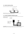
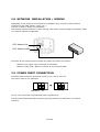
2.8 NETWORK INSTALLATION / WIRING
Depending on the network environment at installation site, connect camera network
connector to the LAN (switch, router, PC...).
Use CAT.5 cable or better for installation.
The camera network interface is auto-sensing, this means normal straight wired patch cable
or crossover cable are supported.
LED: Network link
LED: Network traffic
The LEDs at the network socket inicate the status of network connection:
Network link (right): ON, if network is connected
Network traffic (left): blinks in interval at any network traffic
2.9 POWER INPUT CONNECTION
The EAN-1350 provides a dual power input for 12 V DC or 24 V AC.
The power input is non-polarized:
For 12 V DC connection use stabilized power supplies only.
The camera provides alternative powering by PoE (Power over Ethernet) via network
interface.
15 of 59
3 IP- SETUP
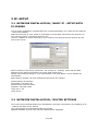
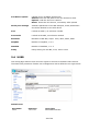
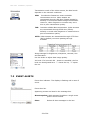
3.1 NETWORK INSTALLATION / BASIC IP - SETUP WITH
IP-FINDER
The IP-Finder application (on application CD in camera package) is a useful tool for initial IP
- setup f the camera.
Start the IP-Finder at a PC, which is connected in to the same network as the camera is or
use a direct network connection camera<>PC.
Click on "Update" to search cameras in your network, the cameras will be listed in the left
side of the screen.
Mark a camera in the list by mouseclick. The current IP - settings, name and the MAC address of the camera are shown now at the right screen side.
Modify the IP settings fitting to your requirements. The field "Name" is free editable for
camera title.
With clicking "Submit" the new settings will be sent to the camera.
Default factory IP settings:
IP-Address: 192.168.0.20
Subnet mask: 255.255.255.0
Gateway: 192.168.0.254
HTTP Port 1: 80
HTTP Port 2: -
3.2 NETWORK INSTALLATION / ROUTER SETTINGS
The router setup methods depend on manufacturer and type. Important is the mapping of IP
- address and port of the camera.
The required port for standard operation is port 80.
Optional installed services may require additional port mappings.
16 of 59
3.3 NETWORK INSTALLATION / BROWSER SETUP
At initial connecting by web browser an installation of the camera ActiveX control is required.
Supported we browsers are Internet Explorer (version 6.0 or higher) or Mozilla Firefox
(version 3.0 or higher) with installed IE-Tab Add-On.
Make sure that user rights at this PC allow installation of ActiveX components.
Set the security level of the browser to "Medium" for ActiveX installation.
Steps:
IE browser > Tools > Internet Options > Security > Custom Level
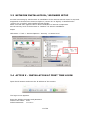
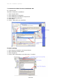
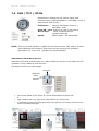
3.4 ACTIVE X - INSTALLATION AT FIRST TIME LOGIN
Open the IE browser and enter the IP address of the camera.
The login screen appears.
Enter the default usermane and password:
Default User name: user1
Default Password: 11111111
17 of 59
Click on OK.
At first time login the installation of the ActiveX control for the camera is required:
18 of 59
4 MAIN OPERATION SCREEN
After successful login the main screen appears:
Switch Live / setup mode
Language
Alarm indicator
Video settings
Video streaming mode
Pan-Tilt control
Video window size
Video streaming format
Alert Log
Video window
File path setup for
record/snapshot
Status display
Single picture snapshot
Local video record
Display file path for
record/snapshot
19 of 59
5 SETTINGS - BASIC SETTING
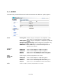
5.1 SETUP SCREEN
To access the detailled camera setup click on "Settings" in upper right corner of the window.
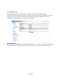
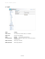
5.2 SYSTEM
The System setting page gives an overview about camera version and basic IP settings.
The values are not editable at this page except the Device name.
20 of 59
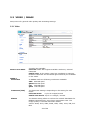
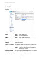
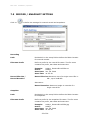
5.2.1 System Log
The administrator can view all login information of this camera, including boot
record, video streaming mode, login IP, changes, and the date/time information. You can
copy the entries to a Word document and save them manually. Please note that all
information is deleted when you turn off the machine.
Syslogd Service
The Syslogd service allows to transmit log informations to a server, which provides Syslogd
function. Enter the Syslogd server IP - Address and the used port to install this function.
21 of 59
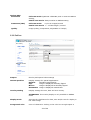
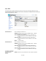
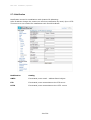
5.3 VIDEO / IMAGE
Setup menu for general video quality and streaming settings.
5.3.1 Video
Sensor Scan Mode
MPEG 4
Resolution
2 modes are available:
Full scan: Mode with highest available resolution, reduced
framerate
Partial scan: In this mode 4 pixel are combined in scanning.
Realtime framerate and enhanced light sensitivity are available
in this mode.
In MPEG4 mode are following resolutions available:
VGA 640x480 pixel
QVGA 320x240 pixel
CIF
352x288 pixel
QCIF 176x144 pixel
Framerate (FPS)
The framerate setting is depending on the setting for scan
mode:
Full scan mode:
12,5 or 8 images/second
Partial scan mode: 25,13 or 9 images / second
Bitrate
The bitrate setting allows to reduce the network bandwidth for
MPEG4 transmission by using higer compression rate. The
image quality is reduced with lower bitrate.
Values: 4096, 3072, 2560, 2048, 1536, 1280, 1024, 768, 512
BPS
22 of 59
Motion JPEG
Resolution
Full scan mode: QuadVGA 1280x960 pixel or same as MPEG4
setting,
Partial scan mode: always similar to MPEG4 setting
Framerate (FPS)
Full scan mode:
12,5 or 8 images/second
Partial scan mode: 1 ~ 12 IPS images / second
Quality
image quality (compression, adjustable in 5 steps)
5.3.2 PreProc
Preproc
Overlay and special video settings
Camera position
Display settings for special applications:
Default:
standard image display
Flip:
image is displayed vertically flipped
Mirror:
image is displayed horizontally flipped
Rotate180: image is displayed rotated 180°
Overlay setting
Display settings for time, date and text overlay.
ATTENTION: This overlay display is only available in MPEG4
mode
Display mode
Activate the checkboxes for date, time and/or text for display in
the video image
Foreground color
Color of characters: clicking in the color box at right opens a
23 of 59
color palette. Select a character color by clicking in a color in
the palette.
Background color
Color of character´s outline: clicking in the color box at right
opens a color palette. Select a outline color by clicking in a
color in the palette.
Display Text
Free editable text / camera title for overlay function
Date Time Position
position of Time / Date overlay in the image:
RT: right top
LT: left top
RB: right bottom
LB: left bottom
Text position
position of Display text overlay in the image:
RT: right top
LT: left top
RB: right bottom
LB: left bottom
5.3.3 Sensor
Enhanced video settings
24 of 59
DayNight Setting
Mode
Mode for day (color) and night (b/w without IR-Cutfilter)
switching:
Auto: automatic switching to dayand night mode, "Status"
shows the current mode (not editable)
Manual: Manual setup of day / night mode
External: D/N switching by external contact, setup under
"EVENT"
Switching delay
Delay of D/N switching in AUTO - mode. Setup range 1~15
seconds. A longer delay time avoids false D/N switching caused
by car light, clouds, reflections or other effects.
Sensitivity level
White Balance
Setting
Mode
Sensitivity treshold value for D/N switching in AUTO mode.
MWB Gain
In manual White Balance mode setup of red (R Gain) and blue
(B Gain) in the range 1~100%
AE Setting
Backlight
White Balance adjustment mode:
Auto:
automatic mode, optimized for most applications
Outdoor: outdoor mode, colder color temperature
Indoor: indoor mode, warmer color temperature
Manual: manual setup of red (R Gain) and blue (B Gain) in the
range 1~100%
Backlight compensation. Activate the checkbox to aloow
baclight compensation. With active BLC adjust the BLC level
from 10 to 100% for optimizeld image result.
Mode
Mode of aperture control:
ALC: mode for use with DC - controlled lenses, combined DC
lens control and automatic electronic shutter (AES)
ELC: mode for lenses with manual iris, automatic electronic
shutter (AES)
Shutter
Electronic shutter: adjustable in ALC mode in the range 1/50 s
to 1/10.000 s,
In ELC mode shuter mode is automatic only.
Slow Shutter
Image interpolation for enhancement of low lux performance,
adjustable in the range 2x to 32x
ATTENTION: For clearer reproduction of moving objects adjust
this value to the lowest possible value!
AGC
Automatic Gain Control, adjustable in 5 steps.
Higher setting creates brighter image in low lux conditions, but
increases also noise in the picture.
25 of 59
5.4 AUDIO
The EAN-1350 provides bidirectional audio transmission with different quality options.
Mode
Audio In
Codec
Gain
Audio out
Codec
Gain
Full duplex: Allows using a microphone and amplifier at the
same time, or turning them off at main page.
Half duplex: Allows using a microphone or amplifier by manual
switch.
Simplex microphone only: Allows using the microphone only.
Simplex amplifier only: Allows using the speaker only.
Audio off:
Turns audio off; i.e. both the microphone and
speaker are inactive.
G726/24:
G726/32:
G711a:
G711u:
Uses
Uses
Uses
Uses
G.726
G.726
G.711
G.711
24Kbps for audio
32Kbps for audio
a-law 64Kbps for
u-law 64Kbps for
encryption.
encryption.
audio encryption.
audio encryption.
Audio in gain (volume) adjustment 10~100%
G726/24:
G726/32:
G711a:
G711u:
Uses
Uses
Uses
Uses
G.726
G.726
G.711
G.711
24Kbps for audio
32Kbps for audio
a-law 64Kbps for
u-law 64Kbps for
decryption.
decryption.
audio decryption.
audio decryption.
Audio out gain (volume) adjustment 10~100%
26 of 59
5.5 PTZ
This Setup page contains settings for electronic zoom and external RS-485 PTZ devices.
The EAN-1350 provides control of 2 PTZ devices, this allows a combined control of electronic
zoom and external PTZ - device.
Camera Diver 1
Driver setting for PTZ driver 1:
EZOOM: electronic zoom (only for MPEG4 mode) , address
setting is not relevant
Pelco-D: setting for external PTZ receiver with Pelco-D
protocol, please set receiver address in the range
0~255
Pelco-P: setting for external PTZ receiver with Pelco-P
protocol, please set receiver address in the range
0~255
None: no PTZ control
Camera Diver 2
Driver setting for PTZ driver 2:
EZOOM: electronic zoom (only for MPEG4 mode) , address
setting is not relevant
Pelco-D: setting for external PTZ receiver with Pelco-D
protocol, please set receiver address in the range
0~255
Pelco-P: setting for external PTZ receiver with Pelco-P
protocol, please set receiver address in the range
0~255
PTZ Driver Manager
Camera Driver...
Delete
Delete: removes current PTZ drivers from camera firmware.
27 of 59
PTZ Driver Upload
Upload of new available PTZ drivers:
Search: Enter the file path to the new PTZ driver files.
Upload: Load the drivers to camera
Reset: Reset the PTZ drivers, neccessary after Upload
Serial port settings
Interface parameter of the RS-485 port, these parameters
should be identical to the PTZ device
Port
Locked at COM 0, no selection needed
Port mode
Locked at RS-485, no selection needed
Baudrate
Baudrate of RS-485, steps: 1200, 2400, 4800, 9600
Stopbits
Number of stopbits, 1 or 2
Databits
Number of databits, 1 or 2
Parity
Parity setting for RS-485, even, odd or none
5.6 USER
This setup page defines users and user rights for access to the EAN-1350 camera.
The EAN-1350 provides a flexible user management with 4 different user right levels.
Default user:
Username
user1
Passwort
11111111
User right
Main Administrator
28 of 59
Add / Modify / Delete User
Press "Add" to define a new user, "Update" to modify the settings for a selected user.
"Delete" removes a user from the list ("user1" can not be deleted).
User setting:
anonymous login
"Enable" allows access to the camera
without login by username /password. This
function could be helpful for public cameras,
for security applications the default setting
"Disable" is recommended.
Maximum number of simultaneous
viewers
If "anonymous login" is set to "Enable",
enter here the number of maximum
anonymous users. The max. limit is 10
users.
anonymous PTZ control
If "anonymous login" is set to "Enable",
enter here, if anonymous users are allowed
to operate PTZ control.
29 of 59
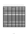
The EAN 1350 provides 4 level of different user rights. The details are listed in table below:
User
Main
Administrator Operator
Administrator
Live View
Record File
Path
System Setting
Video Setting
PreProc
Sensor
Audio Setting
Date / Time
Setting
User Setting
Network
Setting
DDNS setting
PPPoE setting
Streaming
UPnP
SMTP
SAMBA
Notification
Multicast
IP Filter setting
Event Setting
schedule
setting
event server
trigger setting
Motion Setting
Firmware
Upgrade
Factory default
Reboot Setting
PTZ Control
Viewer
9
9
9
9
9
9
9
9
9
9
9
9
9
9
9
9
9
9
9
9
9
9
9
8
8
8
8
8
9
9
8
8
9
8
8
8
9
9
8
8
9
9
9
9
9
9
9
9
9
9
9
9
9
9
9
9
9
9
9
9
8
8
8
8
8
8
8
8
8
9
8
8
8
8
8
8
8
8
8
8
9
9
9
8
9
9
9
9
9
9
9
9
9
8
8
8
9
8
8
8
9
9
9
9
9
9
8
8
9
8
8
8
30 of 59
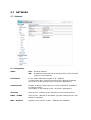
5.7 NETWORK
5.7.1 Network
IP - Assignment
DHCP
OFF: Fixed IP address
ON: IP-address assignment provided by DHCP (requires DHCP
support in the network)
IP-Address
In the mode DHCP ON: display of IP - Address,
in mode DHCP OFF: manual entering of the cameras IP adress
(alternative to the setting by the "IP-Finder" application)
Subnet mask
Display of Subnet mask setting, in mode "DHCP Off" possibility
to change setting
(alternative to the setting by the "IP-Finder" application)
Gateway
Enter the IP - Address of the Gateway of connected network
DNS1 / DNS2
Enter the IP - address of the DNS1 (Dynamic Name Server) and
DNS2 (if available)
MAC - Address
Display of the camera´s MAC - Address (not editable)
EAN-1350
Installation / Operation
5.7.2 Services
The FTP function allows FTP access to the camera. This function is currently not
supported by this camera model.
5.7.3 Streaming
Streaming method
Setting
HTTP
Port 80(80 by default) can pass through most firewalls under
Internet environment. Video streams are transmitted through
HTTP Port (80 by default) to ensure passage through firewalls.
RTSP
Port 554 uses a fixed port (i.e. TCP) or can be defined by users
to ensure reliable data transmission.
Video streams are transmitted through RTSP Port (554 by
default) to avoid video fragment or mosaics due to poor
transmission quality.
RTP
Port 50000 to 60000 are UDP ports and can be defined by users.
They provide the fastest but also most unreliable transmission
service.
Video streams are transmitted through UDP Port (50000~60000
by default) to ensure the fastest image transmission.
Occuring of video fragment or mosaics may occur due to poor
transmission quality are possible.
32 of 59
EAN-1350
Installation / Operation
5.7.4 PPPoE
PPPoE ( Point-to-Point Protocol over Ethernet) is a protocol that supports access to a
high-speed wideband network using a PC and a wideband modem (such as xDSL, Cable,
Wireless modem).
The user need only to equip the PC with an Ethernet card and apply to an ISP and an
ADSL provider for ADSL service to roam the Internet through ordinary twisted copper
wires.
PPPoE is applicable to networking via a xDSL or cable modem. PPPoE setting must be
executed in the LAN environment for your PC to connect to ADSL.
PPPoE
Setting
Dial
On Boot: The camera will establish connection after startup.
Off: PPPoE dialing disabled
Username
Enter the username of your DSL account
Password
Enter the password of your DSL account
33 of 59
EAN-1350
Installation / Operation
5.7.5 DDNS
DDNS (Dynamic Domain Name Service) provides a central (public) database where DNS
information can be stored and retrieved. It allows those using a dynamic IP address (i.e.
one where it changes each time the computer connects to the internet) to be registered
centrally so others can connect to it by name.
Most of the ADSL service providers will provide a dynamic IP for ADSL environments,
which means your IP address will constantly change each time you connect to the
Internet.
As a result, users from WAN environments will have much difficulty finding the correct IP
address. The DDNS (Dynamic DNS service) undates the camera´s IP address when
accessing the web.
Currently the EAN1350 camera supports DDNS service of Dyndns.org. (Oray.net is only
available in chinese language).
DDNS
Setting
Active
Enable: Allow DDNS service
Disable: DDNS service off
Username
Enter the username of your DDNS account
Password
Enter the password of your DDNS account
Domain Name
Domain name of the camera (e.g. my-ean1350.dyndns.org)
34 of 59
EAN-1350
Installation / Operation
5.7.6 UPnP
UPnP (Universal Plug and Play) If you connect your camera to a router, IP allocator, or
wireless AP, the camera will possibly be blocked by the NAT (network address
translation) and can’t be located on the Internet.
To penetrate the firewall, activate the supportive item UPnP. The Link URL shows the
external IP address and the port of the router.
UPnP
Setting
Active
Yes: UPnP function on
No: UPnP function off
UPnP Traversal
Active
Yes: UPnP Traversal active
No: UPnP Traversal disabled
Port range
Range of usable ports, default 32768 ~ 65535
Link URL
Not editable: display of current external IP-Adress of the camera.
If display shows: " http://Trying to traverse..." after pressing
"Safe", the UPnP function failed. Please check settings of PC
peripheral UPnP devices.
35 of 59
EAN-1350
Installation / Operation
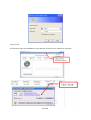
To activate the UPnP function in Windows OS:
Ex: Windows XP:
Windows component installation.
1.
2.
3.
4.
5.
6.
Click Control Panel
Click Add/Remove Programs
Click Add/Remove Windows Components
Click Networking Services
Click Detail
Check / add UPnP User Interface
Firewall settings
1.
2.
2.
3.
Click Windows Firewall in the Control Panel
Open Windows firewall option
Click Exceptions
Check UPnP configuration and edit ports, if needed.
36 of 59
EAN-1350
Installation / Operation
5.7.7 SMTP
SMTP
Setting
SMTP server
Send Mail server domain name / IP- Address
SMTP from
Sender E-mail address
SMTP
authentification
Enable:
enable SMTP authentification
Disable: setting for SMTP server, which work without
authentification
SMTP username
SMTP login username
SMTP password
SMTP login password
37 of 59
EAN-1350
Installation / Operation
5.7.8 SAMBA
The EAN-1350 supports SAMBA server for storage of event snapshots and video
recordings.
SAMBA
Setting
Active
Enable:
Disable:
enable SAMBA server
deactivate SAMBA server
SAMBA
authentification
Enable:
Disable:
enable SAMBA authentification
setting for SAMBA server, which work without
authentification
Username
SAMBA login username
Password
SAMBA login password
Path(ex://ip/folder)
IP adress of the SAMBA server and path of recording folder
Recycle record
Enable:
Disable:
If maximum capacity is reached, oldest recorded
files will be deleted automatically.
If maximum capacity is reached, recording to
Samba will be stopped
Remaining SAMBA
Capacity
Reserved free capacity of SAMBA drive, which is not used for
recordings. (Capacity of recording folder = Total capacity of
Samba drive - entered value in MB)
Shared Folder Size
Shows used and free space of SAMBA folder.
38 of 59
EAN-1350
Installation / Operation
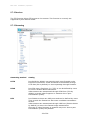
5.7.9 Notification
Notification service for installations with dynamic IP-Adressing.
After IP-Adress change the camera can send out notification by email, ftp or HTTP.
This service is not needed for installations with fixed IP-Address.
Notification
Setting
SMTP
If activated, enter email - address Email subject
FTP
If activated, enter access data to the FTP server
HTTP
If activated, enter access data to the HTTP server
39 of 59
EAN-1350
Installation / Operation
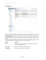
5.7.10 Multicast
This function allows multiple people to watch video streaming without limitation on the
number of users. Multicast is only applicable in the LAN environment.
The function requires support of Multicast function in the connected network.
The video streaming format (MPEG4/MJPEG) depends on the selected image format
setting in Video settings.
Multicast
MPEG-4 / M-JPEG
Setting
(similar setting procedure for both modes)
Enable
On:
Off:
Video Address
Multicast Video streaming adress, IP - range 224.1.1.1 ~
239.255.255.255
Video Port
Multicast Video streaming port, range 2~65534, Even only !
Video TTL
TTL (Time To Live) value of multicast video stream, 1~255
Audio Address
Multicast Audio streaming adress, IP - range 224.1.1.1 ~
239.255.255.255224.1.1.1 ~ 239.255.255.255
Audio Port
Multicast Audio streaming port, range 2~65534, Even only !
Audio TTL
TTL (Time To Live) value of multicast audio stream, 1~255
Event Address
Multicast Event streaming adress, IP - range 224.1.1.1 ~
239.255.255.255
Event Port
Multicast Event streaming port, range 2~65534, Even only !
Event TTL
TTL (Time To Live) value of multicast audio stream, 1~255
MPEG-4 Multicast enabled
MPEG-4 Multicast disabled
40 of 59
EAN-1350
Installation / Operation
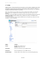
5.7.11 Date / Time
The EAN-1350 camera supports date / time setting in manually, synchronized with client
PC or automatic adjustment by NTP time server.
Date / Time
Setting
Server Time
Current time and date of the camera, display only.
Time setting
Current time and date of client PC, used for function "
"Synchronize with PC´s time"
Time setting
Set time
Mode of time setup:
Synchronize with PC´s time: Client PC date and time are
taken over by the camera
NTP:
Camera time / date is synchronized by NTP
(Network Time Protocol) server
User Input: Manual input of time and date
NTP Server 1 ~ 3
IP - address of NTP servers, 3 servers can be entered optional,
which work redundant
Date
Input field for date only for mode "User Input"
Time
Input field for time only for mode "User Input"
Time zone
Set the time zone depending on the camera´s location. This
setting is mandatory for working in NTP mode.
Daylight Saving
Time
Enable: Switch to Daylight Saving Time (summer period)
manually
Disable: Switch off Daylight Saving Time
Auto:
Automatic DST switching, only in "NTP" mode
Start time
Start date of DST (summer period)
41 of 59
EAN-1350
Installation / Operation
Switch from
Time for switching to DST and updated time
End time
End date of DST
Switch from
Time for switching off DST and updated time
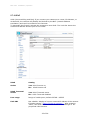
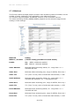
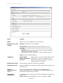
5.7.12 IP Filtering
The EAN-1350 provides IP filtering for network access to the camera based on a blacklist
or whitelist.
IP Filtering
Setting
IP - Filtering
Enable: IP - Filtering active
Disable: IP - Filtering off
Policy
Allow: "whitelist" mode, all entered IP - Adresses can access the
camera, other IP - addresses are blocked
Deny: "blacklist" mode, all entered IP - addresses have no
access to the camera
Filtered IP addresses
Add
For adding an IP - address to the list enter an IP - address below
the list and press "Add".
Remove
To remove an address from filter select an IP - address from the
list and press "Remove".
Remove all
Removes all IP - addresses from the list.
42 of 59
EAN-1350
Installation / Operation
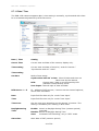
6 SETTINGS - APPLICATION SETTING
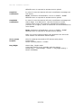
6.1 EVENT
6.1.1 Event
These setup pages provide settings for event related actions such as recording,
notification and contact output.
Add / Modify Event
Press "Add" to define a new event.
Depending on current settings several status / warning messages for event related
settings may appear.
Examples:
Confirm all messages, the event definition menu will open:
43 of 59
EAN-1350
Installation / Operation
Event
Setting
Name
Name of the event (appears in the event list)
Response to event
trigger
Always: permanent event handling
During time: simple weekly schedule function for event
handling, set a start time and a duration of activity (in hours,
max 168)
Example: Event handling shall be activated from Saturday
08:00 am to Monday 8:00 am.
Set Checkbox "Sat"; Start from: 08:00; Duration: 48:00
Never: Event handling disabled
Trigger by
Alarm input:
select input 1,2 or 3 for contact alarm event
Motion detection: Select Area 1, 2 or 3 for motion event
On boot:
select this checkbox to create an event at
camera startup (or reboot)
Response Process
Event actions, multiple selections are possible
Active alarm out
Set this checkbox to switch the contact output of the camera, set
duration time
Upload
video/image to
server
Record event images or videos to FTP or SAMBA server.
Note: A definition of FTP or SAMBA server in NETWORK menu is
required to activate server upload.
Send HTTP
notification
In case of event the camera will send a notification message to a
HTTP server.
Note: A definition of Notification server in EVENT > EVENT
44 of 59
EAN-1350
Installation / Operation
SERVER menu is required to activate server upload.
Send TCP
notification
In case of event the camera will send a notification message to a
TCP server.
Note: A definition of Notification server in EVENT > EVENT
SERVER menu is required to activate server upload.
Send NAP
notification
In case of event the camera will send a notification message and
alarm image to a NAP server. Use this function to create
network alarm event for PowerCon management software
(Version 4.3 or higher). Refer to Powercon 4.3 documentation for
more details.
Note: A definition of Notification server in EVENT > EVENT
SERVER menu is required to activate server upload.
Note: For correct communication with Powercon the device ID
must contain 10 characters without space.
Go to preset
location
Only for cameras mounted to PTZ devices with preset
functionality.
Select a preset position number.
Day/Night
Switch Day / Night mode.
Using this feature is only possible with the setting:
Setup menu > Video/Image > Sensor > Day/Night setting >
Mode: EXTERNAL
45 of 59
EAN-1350
Installation / Operation
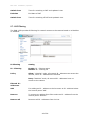
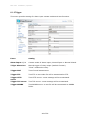
6.1.2 Trigger
This menu provides setting for alarm input contact modes and test functions.
Event
Setting
Alarm Input 1 / 2
Contact mode of alarm inputs, Normal Open or Normal Closed.
Triiger Alarm Out
Manual trigger of relay output (latched function).
"Clear" releases the relay.
Trigger Mail
Test of email transmission.
Trigger FTP
Test FTP: a test video file will be transmitted to FTP.
Trigger HTTP
server
Trigger TCP server
Test HTTP server: a test message will be transmitted.
Trigger SAMBA
Test SAMBA server: a test file will be transmitted to SAMBA
folder.
Test TCP server: a test message will be transmitted.
46 of 59
EAN-1350
Installation / Operation
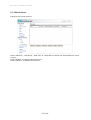
6.1.3 Event Server
Setup for the event servers.
Press "Add FTP", "Add HTTP", "Add TCP" or "Add UDP" to define the access data for event
servers.
Press "Modify" to change selected server.
Press "Remove" to delete event server.
47 of 59
EAN-1350
Installation / Operation
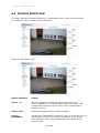
6.2 MOTION DETECTION
The EAN-1350 offers motion detection in 3 independent zones. Zone 3 can be defined
as "Exclusive" zone, no motion will be detected.
Setup of "EXCLUSIVE" zone:
Motion detection
Setting
Area 1 ~ 3
Set the checkbox to enable the motion detection zone.
Click on "AREA1(2,3)" to show the detection area. Click in der
middle of the zone to move the area, click at the borders to
change area size.
Detect level
Detection sensitivity setup, 5 steps available.
Area3 >
EXCLUSIVE
Activate the "EXCLUSIVE" checkbox for zone 3 to set this zone to
"No Detection" mode. This function is useful to cover areas in
other detection zones, where false alarms are expected (e.g.
moving trees)
48 of 59
EAN-1350
Installation / Operation
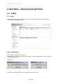
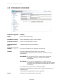
6.3 FIRMWARE UPGRADE
Firmware upgrade
Setting
Model
Shows the camera type
Hardware version
Shows hardware version of the camera
Firmware version
Shows current firmware version
Firmware build
time
Creation date of current firmware
Firmware upgrade
Search
Submit
Enter the file path to the upgrade firmware file
Send the selected firmware file to the camera.
This procedure may take several minutes. follow the screen
instructions.
WARNING: Do not power off the camera during upgrade
procedure. This may damage the camera
irreversible!
WARNING: Do not use low bandwidth or unsafe network
connections to upgrade the camera. An interrupted
connection during update may damage the camera
irreversible!
The camera will reboot after successful update.
Verify the new firmware version after re-login in this menu or
SYSTEM menu.
Load Default settings after firmware upgrade.
Reset
Deletes the selected firmware file path.
49 of 59
EAN-1350
Installation / Operation
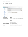
6.4 FACTORY DEFAULT
This menu allows to load factory default values and backup / restore camera settings.
Factory Default
Setting
Resets all settings,
except IP - parameters
All values will be set to factory defaults except the basic
settings for IP parameters.
Resets all parameters
All parameters incl. IP settings are set to factory default
values.
Backup all parameters
Saves the current camera settings in a configuration file.
Confirm to save the file.
Restore all parameters
Loade a camera configuration.
Search
Enter the file path to the EAN1350 configuration file.
Submit
Send the selected configuration file to the camera
Reset
Delete the file path to the configuration file
50 of 59
EAN-1350
Installation / Operation
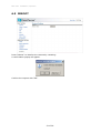
6.5 REBOOT
Press "Reboot" to initialize the camera by restarting.
A confirmation popup will appear.
Confirm the request with "OK".
51 of 59
EAN-1350
Installation / Operation
7 OPERATION
7.1 MAIN SCREEN CONTROLS
After successful login the main screen appears:
Switch Live / setup mode
Language
Alarm indicator
Video settings
Video streaming mode
Pan-Tilt control
Video window size
Video streaming format
Alert Log
Video window
File path setup for
record/snapshot
Status display
Single picture snapshot
Local video record
Display file path for
record/snapshot
7.2 GENERAL AND VIDEO SETTINGS
Control item
Function
Language selection
Selection of videostream, MPEG-4 or Motion JPEG.
Quality, size and framerate depent on the settings in
>SETTING > VIDEO / IMAGE > VIDEO
Display size of the videostream, 1/2x, 1x, 2x, or 4x size.
52 of 59
EAN-1350
Installation / Operation
Transmission mode of the video stream, the ideal mode
depends on the network conditions:
UDP:
Provides the fastest but most unreliable
transmission service. Video steams are
transmitted through UDP Port (50000~60000 by
default) to ensure the fastest image transmission.
However, video fragment or mosaics may occur
due to poor transmission quality.
TCP:
Provides reliable data transmission. Video streams
are transmitted through RTSP Port (554 by
default) to avoid video fragment or mosaics due to
poor transmission quality.
HTTP: Video streams are transmitted through HTTP Port
(80 by default) to ensure passing through
firewalls.
Image settings for Brightness, sharpness, contrast, Hue
and saturation.
Use the slider to adjust best image quality.
Iris level: If a lens with DC - Autoiris is installed, the Iris
level can be adjusted here. "-" closes the iris, "+" opens
the iris.
7.3 EVENT ALERTS
Event alert indicator. The display is flashing red in case of
event.
Event alert list.
Appearing events are listed in the message box.
Alert Snapshot: With activated checkbox a single event
picture will be stored.
Clear:
Delete all alert messages in the box.
53 of 59
EAN-1350
Installation / Operation
7.4 PAN / TILT / ZOOM
Depending on setting the PTZ control works with
electronic zoom (setting EZOOM in > SETTING > PTZ) or
with external PTZ devices.
PTZ-Device:
Select a PTZ device (setup in >
SETTING > PTZ)
Zoom IN / OUT: Zoom In or Out in the picture.
Arrow keys:
Move a zoomed picture
up/down/left/right
Speed:
Speed of pan / tilt movements
NOTE: This way of PTZ operation is global for this video stream. This means, all other
users watching this stream at other client PCs will see this PTZ operation.
Alternative is a "local" PTZ - operation by mouse possible.
Alternative PTZ mode by mouse
Electronic zoom and electronic pan tilt is also possible by mouse, in this mode the PTZ
operation is only visable at local client PC.
Set Mouse focus to the video image.
Zoom In
Drag and
move
zoomed
picture
Zoom Out
•
•
•
use mouse wheel up for Zoom In, mouse wheel down for Zoom out
or
open context menu by right click, select Zoom In / Zoom Out
in zoomed in picture left click and hold in the picture, the mouse will move the
picture up/down/left/right
54 of 59
EAN-1350
Installation / Operation
7.5 RECORD / SNAPSHOT SETTING
Click on
to define the settings for manual record and snapshots.
Recording
Path
Doubleclick in the setup field to define the folder location
for manual records.
Filename Prefix
Define a prefix for the record file name. The file name
contains the prefix, start date and start time.
Example:
Prefix:
Start Date:
Start Time:
Record File Size /
Record Duration
Lobby1_20090128-142524.avi
Lobby1
Jan. 28. 2009
14:25:24
Record file size: Maximum size of a single record file in
MB , up to 2048 MB
alternative:
Record Duration: Maximum lenght in seconds of a
single record file
Snapshot
Path
Doubleclick in the setup field to define the folder location
for snapshots.
Filename Prefix
Define a prefix for the snapshot file name. The file name
contains the prefix, start date and start time.
Example:
Prefix:
Start Date:
Start Time:
Lobby1_20090128-142524.jpg
Lobby1
Jan. 28. 2009
14:25:24
55 of 59
EAN-1350
Installation / Operation
7.6 MANUAL RECORD
Press on "REC" to start a manual record. The file format is AVI. The
storage location is defined by the "PATH" icon.
The icon will start to flash.
A RECORD symbol appears in lower left corner of the video window.
Press "REC" again to stop the record. The record will also stop after
reaching maximum file size / maximum recording duration, which is
defined in "PATH".
Note: Record will also stop with closing the Browser!
7.7 MANUAL SNAPSHOT
Pressing this icon will create a snashot of current video image in JPG format.
The message box below shows the path of saved image:
56 of 59
EAN-1350
Installation / Operation
7.8 AUDIO
The audio fuctionality depends on the installation and on settings in > SETTINGS >
AUDIO.
Listen
Audio transmission from camera to client PC.
Click on the icon to switch the mode.
No audio from camera to client PC.
Click on the icon to switch the mode.
Speak
Audio transmission from client PC to camera.
Click on the icon to switch the mode.
No audio transmission from client PC to camera.
Click on the icon to switch the mode.
7.9 FULL SCREEN MODE
For switching image to full screen right click in the image and select "Full Screen".
In full screen mode press ESC or double click in the window to switch back to normal
screen.
57 of 59
EAN-1350
Installation / Operation
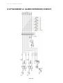
8 ATTACHMENT A: ALARM INTERFACE CIRCUIT
58 of 59
EAN-1350
Installation / Operation
EverFocus Electronics Corp.
Head Office:
12F, No.79 Sec. 1 Shin-Tai Wu Road,
Hsi-Chih, Taipei, Taiwan
www.everfocus.com.tw
China Subsidiary:
Room 609, Technology Trade Building,
Shandgdi Information Industry Base,
Haidian District, Beijing,China
www.everfocus.com.cn
USA Subsidiary:
1801 Highland Ave. Unit A
Duarte, CA 91010, U.S.A.
www.everfocus.com
Japan Subsidiary:
1809 WBG MARIBU East 18F,
2-6 Nakase.Mihama-ku.
Chiba city 261-7118, Japan
www.everfocus.com
European Subsidiary:
Albert-Einstein-Straße 1
D-46446 Emmerich am Rhein, Germany
www.everfocus.de
EAN1350_ma_en_rev01
59 of 59