1
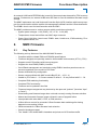
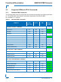
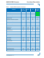
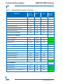
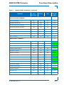
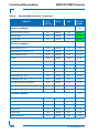
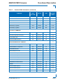
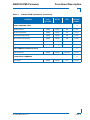
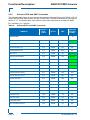
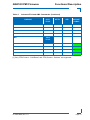
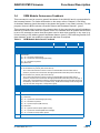
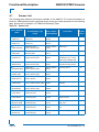
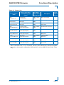
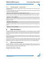
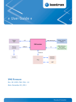
» User Guide «
AM4120
IPMI Firmware
Doc. ID: 1045-9586, Rev. 1.0
November 3, 2011
If it’s embedded, it’s Kontron.
Preface
AM4120 IPMI Firmware
Revision History
Publication Title: AM4120 IPMI Firmware User Guide
Doc. ID: 1045-9586
Rev.
1.0
Brief Description of Changes
Date of Issue
Initial issue
3-Nov-2011
Imprint
Kontron Modular Computers GmbH may be contacted via the following:
MAILING ADDRESS
TELEPHONE AND E-MAIL
Kontron Modular Computers GmbH
+49 (0) 800-SALESKONTRON
Sudetenstraße 7
[email protected]
D - 87600 Kaufbeuren Germany
For further information about other Kontron products, please visit our Internet web site:
www.kontron.com.
Disclaimer
Copyright © 2011 Kontron AG. All rights reserved. All data is for information purposes only and
not guaranteed for legal purposes. Information has been carefully checked and is believed to
be accurate; however, no responsibility is assumed for inaccuracies. Kontron and the Kontron
logo and all other trademarks or registered trademarks are the property of their respective owners and are recognized. Specifications are subject to change without notice.
Page ii
ID 1045-9586, Rev. 1.0
AM4120 IPMI Firmware
Preface
Table of Contents
Revision History .........................................................................................................ii
Imprint ........................................................................................................................ii
Disclaimer ..................................................................................................................ii
Table of Contents ...................................................................................................... iii
List of Tables ..............................................................................................................v
1.
Introduction ...................................................................................1
1.1 Terminology and Acronym Definitions .......................................................... 1
1.2 Related Publications .................................................................................... 2
1.3 IPMI in AdvancedMC / AdvancedTCA Environment .................................... 2
1.4 Module Management Controller Hardware .................................................. 2
2.
MMC Firmware ...............................................................................3
2.1 Key Features ................................................................................................ 3
2.2 Supported IPMI and ATCA Commands ........................................................ 4
3.
2.2.1
Standard IPMI Commands ................................................................... 4
2.2.2
AdvancedTCA and AMC Commands ................................................ 12
OEM Commands and Command Extensions ...........................14
3.1 Get Device ID Command with OEM Extensions ........................................ 14
3.2 Set Control State (Firmware Hub, Boot Order) .......................................... 15
3.3 Get Control State (Firmware Hub, Boot Order) .......................................... 16
3.4 OEM Module Quiescence Feedback ......................................................... 17
4.
3.4.1
Usage if a Shutdown Daemon is Announced as Present .................. 18
3.4.2
Usage if no Shutdown Daemon is Announced as Present ................ 18
Sensors Implemented on the AM4120 .......................................19
4.1 Sensor List ................................................................................................. 20
4.2 Sensor Thresholds ..................................................................................... 22
4.3 OEM Event/Reading Types ........................................................................ 24
ID 1045-9586, Rev. 1.0
Page iii
Preface
5.
AM4120 IPMI Firmware
Firmware Code ............................................................................ 26
5.1 Structure and Functionality .........................................................................26
5.2 Firmware / Module Identification .................................................................26
5.3 Firmware Upgrade ......................................................................................27
6.
5.3.1
Firmware File Formats .......................................................................27
5.3.2
Firmware Upgrade - “ipmitool hpm” ...................................................28
5.3.3
Firmware Upgrade - “ipmitool fwum” ..................................................29
FRU Information ......................................................................... 29
6.1 FRU Version Identification ..........................................................................29
6.2 FRU Data Update .......................................................................................30
7.
E-Keying ...................................................................................... 30
7.1 Board Configuration for E-Keying ...............................................................30
7.2 PCI Express Reference Clock - FCLKA .....................................................30
8.
U-Boot Failover Control - Automatic Flash Selection ............. 31
9.
Hot Swap ..................................................................................... 31
9.1 General .......................................................................................................31
9.2 OS Requirements for Graceful Shutdown ..................................................32
10. OS Support / Tools ..................................................................... 32
10.1 Linux Tools ..................................................................................................32
10.2 OS Support - Board Support Packages ......................................................32
11. IPMI Module Management LEDs ............................................... 33
Page iv
ID 1045-9586, Rev. 1.0
AM4120 IPMI Firmware
Preface
List of Tables
1
Terminology and Acronym Definitions ............................................................ 1
2
Related Publications ...................................................................................... 2
3
Standard IPMI Commands ............................................................................. 4
4
AdvancedTCA and AMC Commands .......................................................... 12
5
Get Device ID Command with OEM Extensions .......................................... 14
6
Set Control State .......................................................................................... 15
7
Get Control State ......................................................................................... 16
8
OEM Module Quiescence Feedback ........................................................... 17
9
Sensor Name Prefix ..................................................................................... 19
10
Sensor List ................................................................................................... 20
11
Thresholds - Standard Temperature Range ................................................. 22
12
Thresholds - Extended Temperature Range ................................................ 22
13
Voltage Sensor Thresholds .......................................................................... 23
14
OEM Event/Reading Types .......................................................................... 24
15
IPMI Module Management LED Functions .................................................. 34
ID 1045-9586, Rev. 1.0
Page v
Preface
AM4120 IPMI Firmware
This page has been intentionally left blank.
Page vi
ID 1045-9586, Rev. 1.0
AM4120 IPMI Firmware
Functional Description
1.
Introduction
1.1
Terminology and Acronym Definitions
The following table provides descriptions for terms and acronyms used in this guide. The descriptions are derived primarily from the IPMI specifications.
Table 1:
Terminology and Acronym Definitions
TERM / ACRONYM
DESCRIPTION
AMC
Advanced Mezzanine Card
BMC
Baseboard Management Controller
BSP
Board Support Package
FRU
Field Replaceable Unit
FWH
Firmware Hub
I 2C
Inter-Integrated Circuit
IPMB
Intelligent Platform Management Bus
IPMB-0
AdvancedTCA shelf-level IPMB
IPMB-L
Local, on-carrier IPMB that links the carrier IPMC with the MMCs of installed modules
IPMC
Intelligent Platform Management Controller located on the AMC carrier
IPMI
Intelligent Platform Management Interface
IOL
IPMI over LAN. An MMC is accessed via LAN, not IPMB.
KCS
Keyboard Controller Style
MMC
Module Management Controller – an IPMI controller located on the AMC module
MP
Management Power
PICMG
PCI Industrial Computer Manufacturer Group
PWR
Payload Power
SDR
Sensor Data Record
SDRR
Sensor Data Record Repository
SEL
System Event Log
SMBIOS
System Management BIOS
SMS
System Management Software (designed to run under the OS)
SOL
Serial over LAN. A serial interface is redirected by LAN using the RMCP+ protocol.
ID 1045-9586, Rev. 1.0
Page 1
Functional Description
1.2
AM4120 IPMI Firmware
Related Publications
The following publications contain information relating to this product.
Table 2:
Related Publications
PRODUCT
PUBLICATION
IPMI
IPMI Specification V2.0
IPMI
IPMI - Platform Management FRU Information Storage Definition v1.0,
Document Revision 1.1
MicroTCA
PICMG® MTCA.0 Micro Telecommunications Computing Architecture R1.0
AMC
PICMG® AMC.0, Advanced Mezzanine Card Specification R2.0
PICMG® AMC.1, PCI Express R2.0
PICMG® AMC.2, Gigabit Ethernet R1.0
PICMG® AMC.4, Serial RapidIO, Rev 1.0
AM4120
AM4120 User Guide, ID 1045-6958
Kontron’s “U-Boot” Bootloader User Guide, ID 1046-1856
IPMI Tools
ipmitool documentation: http://ipmitool.sourceforge.net
IPMI Tools
OpenIPMI documentation: http://www.openipmi.sourceforge.net
As a hot-swappable field-replaceable unit (FRU), the AM4120 follows the stringent carrier
grade RASM feature set, namely - Reliability, Availability, Serviceability, Maintainability.
Built in accordance with the AMC.0 specification, the AM4120 is also compliant with the AMC.1,
AMC.2 and AMC.4 specifications and is easily managed via its management features.
As with every Advanced Mezzanine Card (AMC), the AM4120 is equipped with a Module Management Controller (MMC).
1.3
IPMI in AdvancedMC / AdvancedTCA Environment
The Module Management Controller is a crucial component of any AMC module. Besides acting as a regular IPMI management controller (sensor monitoring, event logging, etc.), it also
provides an interface to all necessary data related to module power requirements and implemented interfaces (E-Keying). Further, it plays an active role in the module hot swap state management. The carrier IPMI Controller (IPMC) communicates with the MMC using the local IPMB
(IPMB-L) bus. In an ATCA/AMC environment, it is the IPMC that actually turns on/off module
(payload) power. However, before the IPMC enables the module payload power, various criteria must be satisfied by both the carrier and the module, including power requirements and capabilities, matching interfaces, current module hot swap state, and any other special conditions
as specified by the Shelf Manager policy.
1.4
Module Management Controller Hardware
On the AM4120 processor AMC module, the MMC is implemented using an NXP® ARM7
microcontroller with 512 kB of internal flash and 56 kB of RAM.
Page 2
ID 1045-9586, Rev. 1.0
AM4120 IPMI Firmware
Functional Description
An external 64 kB serial EEPROM chip is used for firmware private data and for FRU inventory
storage. Furthermore, an external 4 MB serial SPI flash is used for additional firmware image
storage.
The MMC implements one local Keyboard Controller Style (KCS) interface with interrupt support for communication with the system side management software and the U-Boot bootloader.
The IPMB-L bus is used for interconnection with the IPMC.
The MMC provides access to various sensors which permit the monitoring of:
• System power voltages: +12V (PWR), +5V, +3.3V, +3.3V (MP)
• Temperatures: board and airflow near AMC edge-connector
• Power Good, LAN links, board reset, IPMB-L state, Health error, IPMI watchdog, Firmware update/rollback, etc.
2.
MMC Firmware
2.1
Key Features
The following are key features of the AM4120 MMC firmware:
• Compliant with the related IPMI and PICMG® specifications
• Firmware designed and specially made for AdvancedMC environments (ATCA, µTCA)
• Supports one KCS interface with interrupt support
• Supports the local IPMB (IPMB-L) interface
• Out-of-Band management and monitoring using IPMB-L interface permits access to
sensors regardless of the module’s CPU state
• Sensor thresholds fully configurable
• Sensor names prefixed with AMC module Bay ID (A1…4, B1…4)
• Usable in µTCA slots 1…12. Sensor names for slots 9…12 are prefixed with C1…C4
• Complete IPMI watchdog functionality
• Complete FRU functionality
• Firmware can be updated in the field
• Firmware image management may be done by the open tool “ipmitool” (functions “hpm”
or “fwum”)
• Downloading new firmware image does not break currently running firmware activities
• Manual and automatic firmware image roll-back in case of upgrade failure
• Interoperable with other AMC, ATCA, or IPMI solutions
• U-Boot fail-over control for automatic U-Boot firmware bank switching after having
detected a non-working U-Boot
• OEM commands for U-Boot firmware bank selection
• Graceful shutdown support
• The “Health” LED shows MMC's heartbeat and pulses on KCS interface traffic
ID 1045-9586, Rev. 1.0
Page 3
Functional Description
AM4120 IPMI Firmware
2.2
Supported IPMI and ATCA Commands
2.2.1
Standard IPMI Commands
The following table shows an excerpt from the command list specified in the IPMI specification
2.0. The shaded table cells indicate commands supported by the AM4120 MMC.
M = mandatory, O = optional
Table 3:
Standard IPMI Commands
COMMAND
IPMI 2.0
SPEC.
SECTION
NETFN
CMD
IPM DEVICE “GLOBAL” COMMANDS
KONTRON
SUPPORT
ON MMC
M
Get Device ID
20.1
App
01h
M / Yes
Cold Reset
20.2
App
02h
O / Yes
Warm Reset
20.3
App
03h
O / No
Get Self Test Results
20.4
App
04h
O / Yes
Manufacturing Test On
20.5
App
05h
O / No
Set ACPI Power State
20.6
App
06h
O / No
Get ACPI Power State
20.7
App
07h
O / No
Get Device GUID
20.8
App
08h
O / No
Broadcast “Get Device ID”
20.9
App
01h
M / Yes
BMC WATCHDOG TIMER COMMANDS
O
Reset Watchdog Timer
27.5
App
22h
O / Yes
Set Watchdog Timer
27.6
App
24h
O / Yes
Get Watchdog Timer
27.7
App
25h
O / Yes
BMC DEVICE AND MESSAGING COMMANDS
O
Set BMC Global Enables
22.1
App
2Eh
O / Yes
Get BMC Global Enables
22.2
App
2Fh
O / Yes
Clear Message Flags
22.3
App
30h
O / Yes
Get Message Flags
22.4
App
31h
O / Yes
Enable Message Channel Receive
22.5
App
32h
O / Yes
Page 4
ID 1045-9586, Rev. 1.0
AM4120 IPMI Firmware
Table 3:
Functional Description
Standard IPMI Commands (Continued)
IPMI 2.0
SPEC.
SECTION
NETFN
CMD
KONTRON
SUPPORT
ON MMC
Get Message
22.6
App
33h
O / Yes
Send Message
22.7
App
34h
O / Yes
Read Event Message Buffer
22.8
App
35h
O / Yes
Get BT Interface Capabilities
22.9
App
36h
O / No
Get System GUID
22.14
App
37h
O / No
Get Channel Authentication Capabilities
22.13
App
38h
O / No
Get Session Challenge
22.15
App
39h
O / No
Activate Session
22.17
App
3Ah
O / No
Set Session Privilege Level
22.18
App
3Bh
O / No
Close Session
22.19
App
3Ch
O / No
Get Session Info
22.20
App
3Dh
O / No
Get AuthCode
22.21
App
3Fh
O / No
Set Channel Access
22.22
App
40h
O / No
Get Channel Access
22.23
App
41h
O / No
Get Channel Info
22.24
App
42h
O / No
Set User Access
22.26
App
43h
O / No
Get User Access
22.27
App
44h
O / No
Set User Name
22.28
App
45h
O / No
Get User Name
22.29
App
46h
O / No
Set User Password
22.30
App
47h
O / No
Activate Payload
24.1
App
48h
O / No
Deactivate Payload
24.2
App
49h
O / No
Get Payload Activation Status
24.4
App
4Ah
O / No
Get Payload Instance Info
24.5
App
4Bh
O / No
Set User Payload Access
24.6
App
4Ch
O / No
Get User Payload Access
24.7
App
4Dh
O / No
COMMAND
ID 1045-9586, Rev. 1.0
Page 5
Functional Description
Table 3:
AM4120 IPMI Firmware
Standard IPMI Commands (Continued)
IPMI 2.0
SPEC.
SECTION
NETFN
CMD
KONTRON
SUPPORT
ON MMC
Get Channel Payload Support
24.8
App
4Eh
O / No
Get Channel Payload Version
24.9
App
4Fh
O / No
Get Channel OEM Payload Info
24.10
App
50h
O / No
Master Write-Read
22.11
App
52h
O / No
Get Channel Cipher Suits
22.15
App
54h
O / No
Suspend/Resume Payload Encryption
24.3
App
55h
O / No
Set Channel Security Keys
22.25
App
56h
O / No
Get System Interface Capabilities
22.9
App
57h
O / No
COMMAND
CHASSIS DEVICE COMMANDS
O
Get Chassis Capabilities
28.1
Chassis
00h
O / Yes
Get Chassis Status
28.2
Chassis
01h
O / Yes
Chassis Control
28.3
Chassis
02h
O / Yes
Chassis Reset
28.4
Chassis
03h
O / No
Chassis Identify
28.5
Chassis
04h
O / No
Set Chassis Capabilities
28.7
Chassis
05h
O / No
Set Power Restore Policy
28.8
Chassis
06h
O / No
Get System Restart Cause
28.11
Chassis
07h
O / No
Set System Boot Options
28.12
Chassis
08h
O / No
Get System Boot Options
28.13
Chassis
09h
O / No
Get POH Counter
28.14
Chassis
0Fh
O / Yes
EVENT COMMANDS
M
Set Event Receiver
29.1
S/E
00h
M / Yes
Get Event Receiver
29.2
S/E
01h
M / Yes
Platform Event (a.k.a. “Event Message”)
29.3
S/E
02h
M / Yes
Page 6
ID 1045-9586, Rev. 1.0
AM4120 IPMI Firmware
Table 3:
Functional Description
Standard IPMI Commands (Continued)
COMMAND
IPMI 2.0
SPEC.
SECTION
NETFN
CMD
PEF AND ALERTING COMMANDS
KONTRON
SUPPORT
ON MMC
O
Get PEF Capabilities
30.1
S/E
10h
O / No
Arm PEF Postpone Timer
30.2
S/E
11h
O / No
Set PEF Configuration Parameters
30.3
S/E
12h
O / No
Get PEF Configuration Parameters
30.4
S/E
13h
O / No
Set Last Processed Event ID
30.5
S/E
14h
O / No
Get Last Processed Event ID
30.6
S/E
15h
O / No
Alert Immediate
30.7
S/E
16h
O / No
PET Acknowledge
30.8
S/E
17h
O / No
SENSOR DEVICE COMMANDS
M
Get Device SDR Info
35.2
S/E
20h
M / Yes
Get Device SDR
35.3
S/E
21h
M / Yes
Reserve Device SDR Repository
35.4
S/E
22h
M / Yes
Get Sensor Reading Factors
35.5
S/E
23h
O / No
Set Sensor Hysteresis
35.6
S/E
24h
O / Yes
Get Sensor Hysteresis
35.7
S/E
25h
O / Yes
Set Sensor Threshold
35.8
S/E
26h
O / Yes
Get Sensor Threshold
35.9
S/E
27h
O / Yes
Set Sensor Event Enable
35.10
S/E
28h
O / Yes
Get Sensor Event Enable
35.11
S/E
29h
O / Yes
Re-arm Sensor Events
35.12
S/E
2Ah
O / No
Get Sensor Event Status
35.13
S/E
2Bh
O / No
Get Sensor Reading
35.14
S/E
2Dh
M / Yes
Set Sensor Type
35.15
S/E
2Eh
O / No
Get Sensor Type
35.16
S/E
2Fh
O / No
ID 1045-9586, Rev. 1.0
Page 7
Functional Description
Table 3:
AM4120 IPMI Firmware
Standard IPMI Commands (Continued)
COMMAND
IPMI 2.0
SPEC.
SECTION
NETFN
CMD
FRU DEVICE COMMANDS
KONTRON
SUPPORT
ON MMC
M
Get FRU Inventory Area Info
34.1
Storage
10h
M / Yes
Read FRU Data
34.2
Storage
11h
M / Yes
Write FRU Data
34.3
Storage
12h
M / Yes
SDR DEVICE COMMANDS
O
Get SDR Repository Info
33.9
Storage
20h
O / No
Get SDR Repository Allocation Info
33.10
Storage
21h
O / No
Reserve SDR Repository
33.11
Storage
22h
O / No
Get SDR
33.12
Storage
23h
O / No
Add SDR
33.13
Storage
24h
O / No
Partial Add SDR
33.14
Storage
25h
O / No
Delete SDR
33.15
Storage
26h
O / No
Clear SDR Repository
33.16
Storage
27h
O / No
Get SDR Repository Time
33.17
Storage
28h
O / No
Set SDR Repository Time
33.18
Storage
29h
O / No
Enter SDR Repository Update Mode
33.19
Storage
2Ah
O / No
Exit SDR Repository Update Mode
33.20
Storage
2Bh
O / No
Run Initialization Agent
33.21
Storage
2Ch
O / No
SEL DEVICE COMMANDS
O
Get SEL Info
40.2
Storage
40h
O / No
Get SEL Allocation Info
40.3
Storage
41h
O / No
Reserve SEL
40.4
Storage
42h
O / No
Get SEL Entry
40.5
Storage
43h
O / No
Add SEL Entry
40.6
Storage
44h
O / No
Partial Add SEL Entry
40.7
Storage
45h
O / No
Page 8
ID 1045-9586, Rev. 1.0
AM4120 IPMI Firmware
Table 3:
Functional Description
Standard IPMI Commands (Continued)
IPMI 2.0
SPEC.
SECTION
NETFN
CMD
KONTRON
SUPPORT
ON MMC
Delete SEL Entry
40.8
Storage
46h
O / No
Clear SEL
40.9
Storage
47h
O / No
Get SEL Time
40.10
Storage
48h
O / No
Set SEL Time
40.11
Storage
49h
O / No
Get Auxiliary Log Status
40.12
Storage
5Ah
O / No
Set Auxiliary Log Status
40.13
Storage
5Bh
O / No
COMMAND
LAN DEVICE COMMANDS
O
Set LAN Configuration Parameters
23.1
Transport
01h
O / No
Get LAN Configuration Parameters
23.2
Transport
02h
O / No
Suspend BMC ARPs
23.3
Transport
03h
O / No
Get IP/UDP/RMCP Statistics
23.4
Transport
04h
O / No
SERIAL/MODEM DEVICE COMMANDS
O
Set Serial/Modem Configuration
25.1
Transport
10h
O / No
Get Serial/Modem Configuration
25.2
Transport
11h
O / No
Set Serial/Modem Mux
25.3
Transport
12h
O / No
Get TAP Response Codes
25.4
Transport
13h
O / No
Set PPP UDP Proxy Transmit Data
25.5
Transport
14h
O / No
Get PPP UDP Proxy Transmit Data
25.6
Transport
15h
O / No
Send PPP UDP Proxy Packet
25.7
Transport
16h
O / No
Get PPP UDP Proxy Receive Data
25.8
Transport
17h
O / No
Serial/Modem Connection Active
25.9
Transport
18h
O / No
Callback
25.10
Transport
19h
O / No
Set User Callback Options
25.11
Transport
1Ah
O / No
Get User Callback Options
25.12
Transport
1Bh
O / No
SOL Activating
26.1
Transport
20h
O / No
ID 1045-9586, Rev. 1.0
Page 9
Functional Description
Table 3:
AM4120 IPMI Firmware
Standard IPMI Commands (Continued)
IPMI 2.0
SPEC.
SECTION
NETFN
CMD
KONTRON
SUPPORT
ON MMC
Get SOL Configuration Parameters
26.2
Transport
21h
O / No
Set SOL Configuration Parameters
26.3
Transport
22h
O / No
COMMAND
BRIDGE MANAGEMENT COMMANDS (ICMB)
O
Get Bridge State
[ICMB]
Bridge
00h
O / No
Set Bridge State
[ICMB]
Bridge
01h
O / No
Get ICMB Address
[ICMB]
Bridge
02h
O / No
Set ICMB Address
[ICMB]
Bridge
03h
O / No
Set Bridge Proxy Address
[ICMB]
Bridge
04h
O / No
Get Bridge Statistics
[ICMB]
Bridge
05h
O / No
Get ICMB Capabilities
[ICMB]
Bridge
06h
O / No
Clear Bridge Statistics
[ICMB]
Bridge
08h
O / No
Get Bridge Proxy Address
[ICMB]
Bridge
09h
O / No
Get ICMB Connector Info
[ICMB]
Bridge
0Ah
O / No
Get ICMB Connection ID
[ICMB]
Bridge
0Bh
O / No
Send ICMB Connection ID
[ICMB]
Bridge
0Ch
O / No
DISCOVERY COMMANDS (ICMB)
O
Prepare For Discovery
[ICMB]
Bridge
10h
O / No
Get Addresses
[ICMB]
Bridge
11h
O / No
Set Discovered
[ICMB]
Bridge
12h
O / No
Get Chassis Device ID
[ICMB]
Bridge
13h
O / No
Set Chassis Device ID
[ICMB]
Bridge
14h
O / No
BRIDGING COMMANDS (ICMB)
O
Bridge Request
[ICMB]
Bridge
20h
O / No
Bridge Message
[ICMB]
Bridge
21h
O / No
Page 10
ID 1045-9586, Rev. 1.0
AM4120 IPMI Firmware
Table 3:
Functional Description
Standard IPMI Commands (Continued)
COMMAND
IPMI 2.0
SPEC.
SECTION
NETFN
CMD
EVENT COMMANDS (ICMB)
KONTRON
SUPPORT
ON MMC
O
Get Event Count
[ICMB]
Bridge
30h
O / No
Set Event Destination
[ICMB]
Bridge
31h
O / No
Set Event Reception State
[ICMB]
Bridge
32h
O / No
Send ICMB Event Message
[ICMB]
Bridge
33h
O / No
Get Event Destination
[ICMB]
Bridge
34h
O / No
Get Event Reception State
[ICMB]
Bridge
35h
O / No
OEM COMMANDS FOR BRIDGE NETFN
OEM Commands
O
[ICMB]
Bridge
C0h-FEh
OTHER BRIDGE COMMANDS
Error Report
ID 1045-9586, Rev. 1.0
O / No
O
[ICMB]
Bridge
FFh
O / No
Page 11
Functional Description
2.2.2
AM4120 IPMI Firmware
AdvancedTCA and AMC Commands
The following table shows an excerpt from the command lists specified in the PICMG 3.0 R 2.0
AdvancedTCA Base Specification and the PICMG AMC.0 Advanced Mezzanine Card Specification, R 1.0. The shaded table cells indicate commands supported by the AM4120 MMC.
M = mandatory, O = optional
Table 4:
AdvancedTCA and AMC Commands
COMMAND
PICMG 3.0
SPEC.
TABLE
NETFN
CMD
AdvancedTCA
KONTRON
SUPPORT
ON MMC
M
Get PICMG Properties
3-9
PICMG
00h
M / Yes
Get Address Info
3-8
PICMG
01h
N/A
Get Shelf Address Info
3-13
PICMG
02h
N/A
Set Shelf Address Info
3-14
PICMG
03h[1]
N/A
FRU Control
3-22
PICMG
04h
M / Yes [1]
Get FRU LED Properties
3-24
PICMG
05h
M / Yes
Get LED Color Capabilities
3-25
PICMG
06h
M / Yes
Set FRU LED State
3-26
PICMG
07h
M / Yes
Get FRU LED State
3-27
PICMG
08h
M / Yes
Set IPMB State
3-51
PICMG
09h
N/A
Set FRU Activation Policy
3-17
PICMG
0Ah
N/A
Get FRU Activation Policy
3-18
PICMG
0Bh
N/A
Set FRU Activation
3-16
PICMG
0Ch
N/A
Get Device Locator Record ID
3-29
PICMG
0Dh
M / Yes
Set Port State
3-41
PICMG
0Eh
N/A
Get Port State
3-42
PICMG
0Fh
N/A
Compute Power Properties
3-60
PICMG
10h
N/A
Set Power Level
3-62
PICMG
11h
N/A
Get Power Level
3-61
PICMG
12h
N/A
Renegotiate Power
3-66
PICMG
13h
N/A
Get Fan Speed Properties
3-63
PICMG
14h
N/A
Page 12
ID 1045-9586, Rev. 1.0
AM4120 IPMI Firmware
Table 4:
Functional Description
AdvancedTCA and AMC Commands (Continued)
PICMG 3.0
SPEC.
TABLE
NETFN
CMD
KONTRON
SUPPORT
ON MMC
Set Fan Level
3-65
PICMG
15h
N/A
Get Fan Level
3-64
PICMG
16h
N/A
Bused Resource
3-44
PICMG
17h
N/A
Get IPMB Link Info
3-49
PICMG
18h
N/A
COMMAND
AMC
AMC.0
TABLE
Set AMC Port State
3-27
PICMG
19h
O / Yes
Get AMC Port State
3-28
PICMG
20h
O / Yes
Set Clock State
3-44
PICMG
2Ch
O / Yes
Get Clock State
3-45
PICMG
2Dh
O / Yes
[1] Only “FRU Control - Cold Reset” and “FRU Control - Quiesce” are supported.
ID 1045-9586, Rev. 1.0
Page 13
Functional Description
AM4120 IPMI Firmware
3.
OEM Commands and Command Extensions
3.1
Get Device ID Command with OEM Extensions
The IPMI specification defines four optional bytes in the response to Get Device ID. The
response bytes [13:16] hold the 'Auxiliary Firmware Revision Information'.
Table 5:
Get Device ID Command with OEM Extensions
COMMAND
Get Device ID command with OEM extensions
LUN
NetFn
CMD
00h
App = 06h
01h
REQUEST DATA
Byte
-
Data Field
-
RESPONSE DATA
Byte
1
2 - 12
13
Data Field
Completion Code
Regular Get Device ID command response fields
Release number of the MMC firmware:
10h for R10,
11h for R11,
…
14
Module geographical address (site number):
1…8
= Module in AMC bay A1, A2, A3, A4, B1, B2, B3, B4
or in µTCA slot 1 … 8 with bus addresses
72h, 74h, 76h, 78h, 7ah, 7ch, 7eh, 80h
9 …12 = Module in µTCA slot 9 … 12 = Bay C1, C2, C3, C4
with bus addresses 82h, 84h, 86h, 88h
0, > 12 = Module position is not in range. The IPMB-L bus is
switched off
15 - 16
Page 14
Reserved
ID 1045-9586, Rev. 1.0
AM4120 IPMI Firmware
Functional Description
3.2
Set Control State (Firmware Hub, Boot Order)
Table 6:
Set Control State
COMMAND
Set Control State (Firmware Hub, Boot Order)
LUN
NetFn
CMD
00h
OEM = 3Eh
20h
REQUEST DATA
Byte
Data Field
1
Control ID:
00h = Firmware Hub (SPI Flash) Selection
9Dh = Boot Order Configuration
2
Control State for SPI Flash selection:
(These settings are stored in EEPROM and applied (to logic) each time the IPMI controller
detects power-on)
00h = Standard SPI boot flash is selected (default)
01h = Recovery SPI boot flash is selected
Please note that this selection may be forcibly overridden either by DIP-Switch (SW3 switch 2,
refer to the AM4120 User Guide, Table 4-2) or during a bootloader firmware update process.
In case of a failed boot process from the standard SPI NOR flash, the IPMI controller will
select the recovery SPI NOR flash and boot the board again. In case of a boot failure from the
recovery SPI NOR flash, the board locks up. Refer to chapter 8. U-Boot Failover Control.
Control State for Boot Order Configuration:
(These settings are stored in EEPROM and applied (to logic) each time the IPMI controller
detects power-on)
00h = No override, boot as usual (for all other values, refer to the U-Boot User Guide)
RESPONSE DATA
Byte
1
Data Field
Completion Code
ID 1045-9586, Rev. 1.0
Page 15
Functional Description
AM4120 IPMI Firmware
3.3
Get Control State (Firmware Hub, Boot Order)
Table 7:
Get Control State
COMMAND
Get Control State (Firmware Hub, Boot Order)
LUN
NetFn
CMD
00h
OEM = 3Eh
21h
REQUEST DATA
Byte
Data Field
1
Control ID:
00h = Firmware Hub (SPI Flash) Selection
9Dh = Boot Order Configuration
RESPONSE DATA
Byte
Data Field
1
Completion Code
4
Control State (refer to Chapter 3.2, Set Control State)
00h .. 01h for control ID = Firmware Hub SPI Flash Select
00h .. FFh for control ID = Boot Order Configuration
Page 16
ID 1045-9586, Rev. 1.0
AM4120 IPMI Firmware
3.4
Functional Description
OEM Module Quiescence Feedback
This command is used to control a graceful shutdown of the AM4120 and is a prerequisite for
the hot swap feature. For further information on hot swap, refer to Chapter 9, Hot Swap.
A shutdown daemon should be used to shut down the system in an orderly manner. For this
purpose, Kontron’s BSPs include a Graceful Reboot and Shutdown Daemon, “grnsd”.
This command can also be used to set a timeout time for the case that the graceful shutdown
daemon is unable to shut down the system in time. As a default value at system start this time
is set to 20 seconds to ensure that the system can be shut down properly in any case (e.g.
U-boot running or OS without graceful shutdown daemon 'grnsd'). OS's with the graceful shutdown daemon 'grnsd' can modify the quiescent wait time as required.
Table 8:
OEM Module Quiescence Feedback
COMMAND
OEM Module Quiescence Feedback
LUN
NetFn
CMD
00h
OEM = 3Eh
40h
REQUEST DATA
Byte
Data Field
1
Control bits:
[7] - 1b = set quiesce wait timeout
[6] - 1b = quiescence acknowledge (OS ready)
[5] - 1b = OS daemon present
[4:0] Reserved
2
Quiesce wait timeout [sec]
a) An OS daemon is present (refer to bits above):
This is the maximum time from the moment on that the MMC receives FRU Control
(Quiesce) request until it sends back the appropriate Module Hot Swap event message.
b) No OS daemon is present (refer to bits above):
This is the maximum time from the moment on that the MMC receives FRU Control
(Quiesce) request until it sends back the appropriate Module Hot Swap event message. If
sleep state is recognized before timeout, the Module Hot Swap event message will be sent
immediately. If the time is set to 0 (endless wait), the Module Hot Swap event message will
only be sent after recognition of sleep state (signal).
RESPONSE DATA
Byte
Data Field
1
Completion code
2
Control bits:
[7] - Reserved
[6] - 1b = quiescence acknowledge (OS ready)
[5] - 1b = OS daemon present
[4] - 1b = quiesce request (FRU Control)
[3] - Reserved
[2] - 1b = graceful reboot request (FRU Control)
[1] - 1b = quiescence reached (MMC acknowledge)
[0] - 1b = module hot swap switch opened
4
Quiesce wait timeout (valid only if OS daemon present = 1)
ID 1045-9586, Rev. 1.0
Page 17
Functional Description
3.4.1
AM4120 IPMI Firmware
Usage if a Shutdown Daemon is Announced as Present
If a timeout time has to be set to avoid an endless waiting for the sleep state, the daemon calls
this command after system start with the “set quiesce wait timeout” bit set and the “Quiesce
wait timeout” time <> 0. Afterwards, the daemon calls this command cyclically with the “OS
daemon present” bit set. When the MMC gets a FRU Control (Quiesce) request from the carrier
(e.g. during a hot swap sequence), it sets the “quiesce request (FRU Control)” bit in its command response. After the daemon sees this bit set in the response, it should shut down the
system. After having set the “quiesce request (FRU Control)” bit, the MMC starts the timeout
timer (if a timeout time was defined) and monitors the sleep signal line to recognize the sleep
state which should be caused by the shutdown. When the MMC detects the sleep state (signal)
or it receives a command with the “quiescence acknowledge” bit set or the timeout timer has
expired, the MMC sends a “Module Hot Swap Event” message to the carrier, and in the following the payload power will be switched off.
3.4.2
Usage if no Shutdown Daemon is Announced as Present
If no command call announces that a daemon is present, the MMC automatically uses the default timeout time 0 (endless wait) during the hot swap process. But if the timeout time was set
to a value 1…255, this time will be used in any case while waiting for the sleep state (signal).
Settings changed with this command are volatile (in particular quiesce timeout and OS daemon
present). Bits [6:5] are always settable, but once the quiesce request comes, they cannot be
cleared until quiescence state is entered and exited.
Page 18
ID 1045-9586, Rev. 1.0
AM4120 IPMI Firmware
4.
Functional Description
Sensors Implemented on the AM4120
The MMC includes various sensors for voltage or temperature monitoring and various others
for pass/fail type signal monitoring.
Each sensor is associated with a Sensor Data Record (SDR). Sensor Data Records contain
information about the sensor’s identification such as sensor type, sensor name, sensor unit.
SDRs also contain the configuration of a specific sensor such as threshold, hysteresis or event
generation capabilities that specify each sensor's behavior. Some fields of the sensor SDR are
configurable using IPMI commands others are always set to built-in default values.
Finally, one field, which is the sensor owner, must reflect the module’s address that enables the
AMC carrier to identify the owner of the sensor when it is scanned and merged into the AMC
Carrier's SDR repository.
From the IPMI perspective, the MMC is set up as a satellite management controller (SMC). The
MMC supports sensor device IPMI commands and uses the static sensor population feature of
IPMI. All Sensor Data Records can be queried using Device SDR commands.
Each sensor has a name field in its SDR. The sensor name has a prefix, which is automatically
adapted, dependent on the physical position of the module in a carrier or in a µTCA chassis.
The following prefixes are used for all sensors of an AMC module:
Table 9:
Sensor Name Prefix
AMC Bay
1
2
3
4
5
6
7
8
-
-
-
-
μTCA slot
1
2
3
4
5
6
7
8
9
10
11
12
Sensor Name
Prefix
A1:
A2:
A3:
A4:
B1:
B2:
B3:
B4:
C1:
C2:
C3:
C4:
Module sensors that have been implemented are listed in the sensor list below.
ID 1045-9586, Rev. 1.0
Page 19
Functional Description
4.1
AM4120 IPMI Firmware
Sensor List
The following table indicates all sensors available on the AM4120. For further information on
Kontron’s OEM specific sensor types and sensor event type codes presented in the following
table, please refer to Chapter 4.3, OEM Event/Reading Types.
Table 10: Sensor List
Sensor Type (Code) /
Event/Reading Type
(Code)
Ass. Mask /
Deass. Mask /
Reading Mask
00h /
A1:IPMI Info-1
OEM Firmware Info 1 (C0h) /
OEM (70h)
0003h / 0000h /
7FFFh
For internal use only
N
01h /
A1:IPMI Info-2
OEM Firmware Info 2 (C0h) /
OEM (71h)
0003h / 0000h /
7FFFh
For internal use only
N
02h /
A1:IPMI Watchdog
Watchdog (23h) /
Sensor-specific (6Fh)
010Fh / 0000h /
010Fh
Watchdog 2
Y
03h /
A1:FRU Agent
OEM (C5h) /
Discrete (0Ah)
0140h / 0000h /
0147h
FRU agent
N
04h /
A1:Health Error
Platform Alert (24h) /
Digital discrete (03h)
0000h / 0000h /
0003h
Aggregate states (power,
temperature, etc.). Visualization by the Health LED.
Y
05h /
A1:MMC Reboot
Platform Alert (24h) /
Digital discrete (03h)
0002h / 0000h /
0003h
MMC reboot active state. Is
asserted during boot time.
N
06h /
A1:ModuleHotSwap
OEM (F2h) /
Sensor-specific (6Fh)
001Fh / 0000h /
001Fh
Hot swap sensor
N
07h /
A1:IPMBL State
OEM (C3h) /
Sensor-specific (6Fh)
0007h / 0000h /
000Fh
State of IPMB-L bus
N
08h /
A1:MMC Stor Err
Mgmt. Subsyst. Health (28h) / 0002h / 0000h /
Sensor-specific
0003h
Storage error
N
0Ah /
A1: MMC FwUp
Firmware Upgrade Manager
(C7h) / Sensor specific (6Fh)
010Fh / 0000h /
010Fh
Status of Firmware Upgrade
Manager
N
0Dh /
A1:Board Reset
OEM (C4h) /
Sensor-specific (6Fh)
04DEh / 0000h /
04DEh
Board reset event
Y
0Eh /
A1:Temp Board
Temperature (01h) /
Threshold (01h)
7A95h / 7A95h /
3F3Fh
Board temperature
Y
0Fh /
A1:Temp AMC In
Temperature (01h) /
Threshold (01h)
7A95h / 7A95h /
3F3Fh
Air temperature near AMC
edge-connector
Y
13h /
A1:Board 3.3vIPM
Voltage (02h) /
Threshold (01h)
2204h / 2204h /
1212h
AMC Management Power
(MP) 3.3V
Y
14h /
A1:Board 12.0v
Voltage (02h) /
Threshold (01h)
2204h / 2204h /
1212h
AMC Payload Power (PWR)
12V
Y
15h /
A1:Board 5.0V
Voltage (02h) /
Threshold (01h)
2204h / 2204h /
1212h
Board 5V supply
Y
Sensor Number /
Name
Page 20
Description
Health
LED Red
on Error
ID 1045-9586, Rev. 1.0
AM4120 IPMI Firmware
Functional Description
Table 10: Sensor List
Sensor Type (Code) /
Event/Reading Type
(Code)
Sensor Number /
Name
Ass. Mask /
Deass. Mask /
Reading Mask
Description
Health
LED Red
on Error
16h /
A1:Board 3.3V
Voltage (02h) /
Threshold (01h)
2204h / 2204h /
1212h
Board 3.3V supply
Y
17h /
A1:Pwr Good
Power supply (08h) /
OEM (77h)
0000h / 0000h /
0887h
States of all power lines
N
18h /
A1:Pwr Good Evt
Power supply (08h) /
OEM (77h)
0000h / 0887h /
0887h
Power fail events for all
power lines
Y
1Ah /
A1:FWH0 Boot Err
Boot Error (1Eh) /
Sensor-specific (6Fh)
0008h / 0008h /
0008h
Firmware Hub 0 boot error
Y
1Bh /
A1:FWH1 Boot Err
Boot Error (1Eh) /
Sensor-specific (6Fh)
0008h / 0008h /
0008h
Firmware Hub 1 boot error
Y
1Dh /
A1:Lan AMC0 Link
LAN (27h) /
Sensor-specific (6Fh)
0000h / 0000h /
0003h
LAN link status –
AMC port 0
N
* 1Eh /
A1:Lan AMC1 Link
LAN (27h) /
Sensor-specific (6Fh)
0000h / 0000h /
0003h
LAN link status –
AMC port 1
N
* 1Fh /
A1:Lan FrontA Lk
LAN (27h) /
Sensor-specific (6Fh)
0000h / 0000h /
0003h
LAN link status –
Front port A
N
20h /
A1:Lan FrontB Lk
LAN (27h) /
Sensor-specific (6Fh)
0000h / 0000h /
0003h
LAN link status –
Front port B
N
* Either “Lan AMC1 Link” or “Lan FrontA Lk” sensor is valid. Which one is valid and readable,
depends on the board's configuration (SW2 switch 2, refer to AM4120 User Guide, Table
4-1).
ID 1045-9586, Rev. 1.0
Page 21
Functional Description
4.2
AM4120 IPMI Firmware
Sensor Thresholds
The AM4120 CPU module is available for two different operating temperature ranges. For each
operating temperature range, a set of temperature thresholds for the sensors is defined. The
standard temperature range uses thresholds defined by Table 11, and the extended temperature range uses thresholds defined by Table 12. Table 13 provides voltage sensor thresholds.
Table 11: Thresholds - Standard Temperature Range
Sensor Number /
ID String
0Eh /
A1:Temp
Board
0Fh /
A1:Temp
AMC In
Upper non-recoverable
75 °C
75 °C
Upper critical
70 °C
70 °C
Upper non-critical
65 °C
65 °C
Normal max.
60 °C
60 °C
Nominal
55 °C
55 °C
Normal min.
0 °C
0 °C
Lower non-critical
-5 °C
-5 °C
Lower critical
-7 °C
-7 °C
Lower non-recoverable
-10 °C
-10 °C
Table 12: Thresholds - Extended Temperature Range
Sensor Number /
ID String
0Eh /
A1:Temp
Board
0Fh /
A1:Temp
AMC In
Upper non-recoverable
90 °C
90 °C
Upper critical
85 °C
85 °C
Upper non-critical
80 °C
80 °C
Normal max.
75 °C
75 °C
Nominal
70 °C
70 °C
Normal min.
0 °C
0 °C
Lower non-critical
-40 °C
-40 °C
Lower critical
-42 °C
-42 °C
Lower non-recoverable
-45 °C
-45 °C
Page 22
ID 1045-9586, Rev. 1.0
AM4120 IPMI Firmware
Functional Description
Table 13: Voltage Sensor Thresholds
Sensor Number /
ID String
Upper non-recoverable
17h /
A1:Board
3.3vIPM
18h /
A1:Board 12.0v
19h /
A1:Board 5.0V
1Ah /
A1:Board 3.3V
n.a.
n.a.
n.a.
n.a.
3.50 V
13.4 V
5.36 V
3.50 V
n.a.
n.a.
n.a.
n.a.
Normal max.
3.46 V
13.2 V
5.31 V
3.46 V
Nominal
3.30 V
12.0 V
5.00 V
3.30 V
Normal min.
3.13 V
10.8 V
4.70 V
3.13 V
n.a.
n.a.
n.a.
n.a.
3.11 V
10.7 V
4.67 V
3.11 V
n.a.
n.a.
n.a.
n.a.
Upper critical
Upper non-critical
Lower non-critical
Lower critical
Lower non-recoverable
ID 1045-9586, Rev. 1.0
Page 23
Functional Description
4.3
AM4120 IPMI Firmware
OEM Event/Reading Types
Kontron’s OEM specific sensor types and sensor event type codes are presented in the following table.
Table 14: OEM Event/Reading Types
OEM
SENSOR
TYPE (CODE)
OEM
EVENT/READING
TYPE (CODE)
DESCRIPTION
Firmware Info 1 (C0h)
70h
Internal Diagnostic Data
Firmware Info 2 (C0h)
71h
Internal Diagnostic Data
Board Reset (C4h)
6Fh
(sensor type specific)
Sensor-specific
Offset
Event
00h
Reserved
01h
HwPowerReset
02h
PCIReset
03h
HwWatchDogReset
04h
SoftReset
05h
Reserved
06h
ColdReset
07h
IPMICommand
08h
Reserved
09h
Reserved
0Ah
BMCWatchdog
Sensor discrete
State
Meaning
08h
IPMB-L running
others
IPMB-L not running
IPMBL State (C3h)
Page 24
6Fh
(sensor type specific)
ID 1045-9586, Rev. 1.0
AM4120 IPMI Firmware
Functional Description
Table 14: OEM Event/Reading Types (Continued)
OEM
SENSOR
TYPE (CODE)
Firmware Upgrade Manager
(C7h)
Power Supply (08h) i.e. for
Power Good /
Power Good Event
ID 1045-9586, Rev. 1.0
OEM
EVENT/READING
TYPE (CODE)
6Fh
(sensor type specific)
77h
(OEM)
DESCRIPTION
Sensor-specific
Offset
Event
0h
First Boot after upgrade
1h
First Boot after rollback (error)
2h
First Boot after errors (watchdog)
3h
First Boot after manual rollback
4h
Reserved
5h
Reserved
6h
Reserved
7h
Reserved
8h
Firmware Watchdog Bite, reset
occurred
Sensor-specific
Offset
Event
0h
12V good (PWR)
1h
5V good
2h
3V3 good
3h
Reserved
4h
Reserved
5h
Reserved
6h
Reserved
7h
vccCore good
8h
Reserved
9h
Reserved
Ah
Reserved
Bh
3V3IPMI good (MP)
Ch
Reserved
Page 25
Functional Description
AM4120 IPMI Firmware
Table 14: OEM Event/Reading Types (Continued)
OEM
SENSOR
TYPE (CODE)
Hot Swap Sensor (F2h)
OEM
EVENT/READING
TYPE (CODE)
6Fh
(sensor type specific)
DESCRIPTION
Sensor-specific
Offset
Event
00h
Handle close
01h
Handle open
02h
Quiesced
03h
Backend Power Failure
04h
Backend Power Shutdown
5.
Firmware Code
5.1
Structure and Functionality
MMC firmware code is organized into boot code and operational code (IPMI firmware). Both
are stored in the internal flash of the micro-controller.
An additional external SPI NOR flash device is used for holding two copies of the operational
code. One copy will always be the active operational code. The other firmware copy will either
be a newly downloaded firmware or the 'previously good' operational code for rollback.
Upon an MMC start or reset, the controller first executes the boot code. The boot code will
check the status of the firmware and calculate a checksum of the operational code. Upon successful verification of the operational code checksum, the firmware will execute the operational
code. The operational code is upgradable in the field.
5.2
Firmware / Module Identification
IPMI provides two methods to identify the AM4120 MMC firmware:
• Issuing the IPMI Command Get Device ID
• Reading the Device Locator Record (SDR Type 12h)
A full description of the IPMI command Get Device ID and the Device Locator Record
(SDR Type 12h) can be found in the IPMI specification. For further information refer to Table
2, Related Publications.
IPMI Command: Get Device ID
The response on the IPMI command Get Device ID offers the following information (among
others):
Manufacturer ID = 3A98h / 15000d (Kontron IANA ID)
Device ID = 20h (NXP ARM7 microcontroller)
Product ID = identifies the firmware (its board family firmware)
Page 26
ID 1045-9586, Rev. 1.0
AM4120 IPMI Firmware
Functional Description
• Firmware revision (byte 4:5) reflects the core version of the running firmware, which will
change only after major functional update.
• SDR revision (byte 13, OEM extension) will be incremented with each firmware update
For a description of the OEM extensions refer to Chapter 3.1, “Get Device ID Command with
OEM Extensions”.
Device Locator Record
The Device Locator Record (SDR Type 12h) contains a Device ID String which identifies the
MMC as AM4120 MMC. Additionally, some run-time information such as AMC slot and slot-dependent IPMB address is available in this record.
For example, when using the Linux “ipmitool” on a AM4120 placed in the first AMC slot of a
µTCA system, by calling:
ipmitool sdr list mcloc
the following information is displayed:
A1:AM4120 | … @72h | ok
5.3
Firmware Upgrade
The standard way to upgrade the MMC's operational code is to use the open tool “ipmitool” (see
Table 2, Related Publications). This tool allows download and activation of new operational
code and also a rollback to the “last known good” operational code. Additionally, the status and
the firmware version of the firmware copies can be checked.
For local or remote firmware upgrade, the following IPMI interfaces are available:
• KCS interface (local, requires active payload, but fast)
• IPMB (remote, independent of the payload state)
During the download process, the currently running operational code operates as usual until
the activation command is issued. During the activation process, the MMC is off-line for about
20 seconds while the boot code is re-organizing the firmware storage. Afterwards, it starts the
new operational code. If this doesn't succeed, after a timeout the boot code performs an automatic rollback to the “last known good” operational code.
5.3.1
Firmware File Formats
Firmware images for upgrade are provided in two formats:
• Firmware in binary format, e.g. FW_IPMI_<BOARD>_<REL>_FWUM.bin,
for usage with “ipmitool fwum ..” commands
• Firmware images in the PICMG defined HPM.1 file format,
e.g. FW_IPMI_<BOARD>_<REL>_FWUM.hpm,
for usage with “ipmitool hpm ..” commands
where:
<BOARD> indicates board family of the MMC’s firmware
<REL> indicates release (version) of MMC’s firmware
ID 1045-9586, Rev. 1.0
Page 27
Functional Description
5.3.2
AM4120 IPMI Firmware
Firmware Upgrade - “ipmitool hpm”
Firmware upgrade using a HPM.1 file requires at least “ipmitool” version 1.8.10.
The firmware upgrade procedure starts with downloading the HPM.1 file using, for example,
the following command:
ipmitool hpm upgrade <HPM.1_FWFile>.hpm all
The next step is the activation of the newly downloaded MMC firmware. This is done using:
ipmitool hpm activate
Detailed information about the active firmware image or the inactive image can be obtained
using the commands mentioned below.
To obtain detailed version information of the active MMC firmware, use the following command:
ipmitool hpm compprop 1 1
To obtain the version information of the rollback image (only valid if a newly downloaded firmware is already activated), use the following command:
ipmitool hpm compprop 1 3
To obtain the version information of the newly downloaded MMC firmware (only valid after
download and before activation), use the following command:
ipmitool hpm compprop 1 4
To obtain detailed information about the MMC’s HPM.1 upgrade capabilities, use the following
command:
ipmitool hpm targetcap
To perform a manual rollback to the previously good firmware image, use the following command:
ipmitool hpm rollback
Page 28
ID 1045-9586, Rev. 1.0
AM4120 IPMI Firmware
5.3.3
Functional Description
Firmware Upgrade - “ipmitool fwum”
“ipmitool” version 1.8.9 doesn’t support HPM.1 correctly. Tool versions prior to this do not support HPM.1 at all.
The firmware upgrade procedure starts with the download of the binary firmware file using, for
example, the following command:
ipmitool fwum download <Binary_FWFile>.bin
The next step is the activation of the newly downloaded MMC firmware. This is done using:
ipmitool fwum upgrade
Detailed information about the active and inactive firmware images can be obtained using the
following command:
ipmitool fwum status
To perform a manual rollback to the previously good firmware image, use the following command:
ipmitool fwum rollback
6.
FRU Information
The MMC provides 4 kB of non-volatile storage space for FRU information. Some of the data
stored there, such as the Module Current Requirements record or E-Keying information (refer
to AMC.0 specification for details), are mandatory for module functionality in an ATCA/AMC environment.
Please note that missing FRU information possibly will prevent the AMC module from being accepted by the carrier controller during the hot swap process, and the module will possibly not
receive payload power.
Full low-level access to read or write a module's FRU information is provided by regular IPMI
FRU Device commands. Please be careful when writing FRU information directly using standard IPMI commands. Damaging the FRU information may lead to a non-working payload.
6.1
FRU Version Identification
The FRU data fields, as defined in the IPMI - Platform Management FRU Information Storage
Definition v1.0, Rev 1.1, are used to record the version of the FRU installed. The revision number is incremented for each new release of FRU data.
Example of board FRU ID: “STD_R01”
Example of product FRU ID: “STD_R01”
ID 1045-9586, Rev. 1.0
Page 29
Functional Description
6.2
AM4120 IPMI Firmware
FRU Data Update
Update of the FRU data can be done via regular IPMI FRU device commands. The correct FRU
data must be prepared at the factory.
7.
E-Keying
E-Keying has been defined in the AMC.0 R2.0 Specification to prevent module damage, prevent malfunctions, and verify bay connection compatibility. Therefore, the FRU data of an AMC
module contains PICMG-defined records which describe the module’s AMC interoperability:
• Module Current Requirements Record
• Clock Configuration Record, for the PCI Express reference clock
• AMC Point-to-point Record, describing module’s AMC port capabilities
The IPMI commands Set AMC Port State and Get AMC Port State defined by the
AMC.0 specification are used by the carrier or MCH for either granting or rejecting the E-Keys
(i.e. enabling or disabling of AMC ports during E-Keying).
Which AMC port connections are activated is decided during E-Keying. The information which
AMC port is enabled or not, can be directly read from the board’s E-Keying configuration registers (IAKEY0, IAKEY1 and IAKEY2) at addresses 0x298 / 0x299 / 0x29Ah.
7.1
Board Configuration for E-Keying
The AM4120 supports either a Serial RapidIO interface (default) or a PCI Express interface in
the AMC port Fat Pipes region.
The required interface settings must be configured via DIP Switch SW2.
For further information, refer to the AM4120 User Guide, Chapter 4.1 DIP Switch Configuration.
7.2
PCI Express Reference Clock - FCLKA
Both sides (Root Complex and Endpoint) of a PCI Express connection should be driven by a
common reference clock. The PCI Express reference clock may be generated locally by the
module or acquired from the AMC connector.
When the AM4120 is configured as PCI Express Root Complex, it may act either as clock receiver or as clock source. If configured as PCI express Endpoint, the AM4120 is acting as clock
receiver only. Both are described by the Clock Configuration Record (for the PCI Express reference clock) and defined by the “AMC.1 R2.0, PCI Express on AMC” specification.
The DIP Switch SW3 can be used to overwrite the clock configuration (clock receiver, clock
source, etc.) regardless of the E-Keying results. Please refer to the AM4120 User Guide for details.
Clock Receiver:
The PCI Express reference clock provided by the carrier may be slightly modulated (SSC Spread Spectrum Clock). The FRU E-Keying data for the AM4120 contains two AMC link descriptors for each PCI Express channel, one with SSC (priority 1) or with non-SSC (priority 2).
The carrier’s IPMC selects the “matching” link descriptor (SSC or non-SSC) during E-Keying
using the Set AMC Port State command.
Page 30
ID 1045-9586, Rev. 1.0
AM4120 IPMI Firmware
Functional Description
Clock Source:
When the AM4120 acts as clock source for the PCI Express reference clock, the clock signal
must be routed also to the PCI Express Endpoint. The backplane, the carrier’s IPMC or the
MCH must be capable of doing this (Clock E-Keying according to AMC.1 R2.0).
The information whether the AMC clock or the local clock is used as PCI Express reference
clock can be directly read from the board’s E-Keying clock configuration register (ICKEY0) at
address 0x297.
The DIP Switch SW3 can be used to forcibly configure the PCI Express reference clock. Please
refer to the AM4120 User Guide for details.
8.
U-Boot Failover Control - Automatic Flash
Selection
For normal operation, the MMC specifies the standard SPI NOR flash to be used for booting
and starts the payload. Then it waits for a message from the U-Boot bootloader. This message
contains a checksum report, i.e. it reports whether the boot flash's checksum is valid.
If either the checksum is invalid or the message is not received within a given time, the currently
used SPI NOR flash is assumed to contain a corrupted image. In this case, the MMC generates
a "Boot Error - Invalid boot sector" event for the related sensor. The sensor "FWH0 Boot Err"
indicates the boot error and generates the event for the standard SPI NOR flash. When booting
from the standard SPI NOR flash fails, the MMC selects the recovery SPI NOR flash, then the
board processor is reset and the MMC waits for the checksum report message from U-Boot
again.
In the event the recovery SPI NOR flash boot is successful, payload control is turned over to
U-Boot.
If again the checksum is invalid or the message is not received within a given time, the MMC
indicates the boot error with sensor "FWH1 Boot Err" and generates the event. The MMC remains operable, however, now some form of intervention (human) on the part of the IPMI management system is required to resolve the failure of the module to properly boot.
9.
Hot Swap
9.1
General
As a hot-swappable field replaceable unit (FRU), the AM4120 also follows the same stringent
carrier grade RASM feature set, namely - Reliability, Availability, Serviceability, Maintainability.
When offered in combination with AdvancedTCA platforms, TEM (Telecom Equipment Manufacturers) clients literally conserve valuable system AdvancedTCA system slots. The AM4120
supports full hot swap capability as per PICMG 3.0. It can be removed from or installed in a
running system without powering-down the system. Please refer to the PICMG 3.0 specification for additional details.
During hot swap of a working module, the payload side has to be shut down automatically on
command of the MMC and the end of shutdown has to be signalled back to the MMC.
ID 1045-9586, Rev. 1.0
Page 31
Functional Description
9.2
AM4120 IPMI Firmware
OS Requirements for Graceful Shutdown
Requirements:
• At system start on the payload side, the Kontron shutdown daemon “grnsd” must be started. It is included in the Linux board support packages for the AM4120. This daemon communicates cyclically with the MMC for the exchange of states, commands and
acknowledges. For this, it uses the OEM Module Quiescence Feedback command.
Refer to Chapter 3.4.
Hot swap operation sequence processed by MMC and OS:
• On command of the carrier controller the MMC sets a “shut down request” flag.
• The “grnsd” daemon recognizes this request in the response to its cyclical OEM Module
Quiescence Feedback command and initiates the shutdown of the payload software
system.
• At the end of the shutdown process, the “grnsd” daemon informs the MMC by setting the
appropriate flag when calling the OEM Module Quiescence Feedback command.
• The MMC reports this to the carrier controller so that the hot swap processing can be continued and finished.
By default the MMC waits endlessly for this information. If an endless wait is to be avoided, it
is possible to set a timeout time after which the system will be switched off unconditionally. For
the setting of the timeout refer to Chapter 3.4, OEM Module Quiescence Feedback.
10.
OS Support / Tools
10.1
Linux Tools
OpenIPMI - KCS driver
Normally all drivers and kernel modules needed for communication between the payload
software and the MMC firmware via the KCS interface come with the distribution. The
OpenIPMI library package includes some applications and the required libraries.
“ipmitool”
Another very useful all-in-one tool is the “ipmitool” (http://ipmitool.sourceforge.net). It provides
a user-friendly interface to many IPMI features and extensions, for example, to get sensor
readings, change sensor thresholds or access other Management Controllers via IPMB. Before
“ipmitool” can be used, the OpenIPMI driver mentioned above must be loaded too.
10.2
OS Support - Board Support Packages
To see which Operating Systems are supported refer to the board's data sheet. Please visit
http://www.kontron.com to get the data sheet. Please also have a look in the download section
for latest versions of Board Support Packages or Firmware Updates.
For further information concerning IPMI, refer to the BSP documentation for the respective OS.
Page 32
ID 1045-9586, Rev. 1.0
AM4120 IPMI Firmware
11.
Functional Description
IPMI Module Management LEDs
There are three IPMI Module Management LEDs on the front panel of the AM4120. The following figure illustrates an AM4120 module and the location of the LEDs.
3
2
A
IPMI Module Management LEDs
LED1 (Out-of-Service LED)
LED2 (Health LED)
1
HS LED (Hot Swap LED)
B
0
AM4120
ID 1045-9586, Rev. 1.0
Page 33
Functional Description
AM4120 IPMI Firmware
The following table describes the functions of the IPMI Module Management LEDs.
Table 15: IPMI Module Management LED Functions
OVERRIDE MODE
LED
LED1
COLOR
red
(Out-ofService
LED)
LED2
(Health
LED)
STATE
selectable by user or
carrier, depending on
PICMG LED
command
NORMAL MODE
off
Default
By user:
on
MMC out of service or in reset state
blinking
MMC firmware upgrade
• Only lamp test
green/
green: blinking
MMC running showing its heartbeat By user:
red+amber
• Only lamp test
green: blinking and pulsing MMC heart beat and KCS traffic
red: on +
amber: blinking
Health error detected +
MMC heart beat
red: on +
Health error detected +
amber: blinking and pulsing MMC heart beat and KCS traffic
HS LED
blue
on
(Hot Swap
LED)
Page 34
By carrier:
a) Module ready for hot swap
extraction, or
b) Module has just been inserted in
a powered system
blinking
Module hot swap in progress;
module not ready for extraction
off
Module is in normal operation
• On
• Off
• Slow/Fast Blinking
By user:
• Only lamp test
ID 1045-9586, Rev. 1.0