1
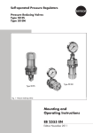
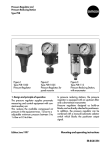
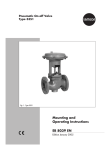
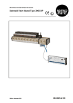
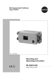
Position Indicator
Typ 4748
Fig. 1 ⋅ Type 4748
1. Design and principle of operation
The Type 4748 Position Indicator is used to
ensure a certain relationship between the
valve position (travel) and the analog output
signal of 4 to 20 mA.
If the output signal of the position indicator is
transmitted to e.g. an indicating instrument,
the current valve travel can be checked and
monitored.
Edition March 1993
The position indicator is mounted to pneumatic control valves designed as either castiron yoke valves acc. to Namur or valves with
rod-type yokes (direct attachment to valve)
respectively. Furthermore, the position indicator can be used in combination with the
Type 763 or 765-2 Positioners (positioner attachment).
Mounting and operating instructions
EB 8363 E
The valve travel is converted into a rotary motion which is transmitted via pin (1.1) and
lever (1) to the solenoid system (2) of the position indicator. As a result, the magnetic field
changes and in this way also the voltage in
the Hall-sensor (2). The electronic components connected behind the sensor convert
this voltage into a load-independent current
signal of 4 to 20 mA.
1
For adjustment of zero and span, the position
indicator is provided with 4 micro-switches
(preadjustment) and 2 potentiometers (fine
adjustment). The output characteristic of the
position indicator can be reversed by means
of a plug which must be turned 180°. This
means, the valve position "CLOSED" can be
optionally indicated by either 4 or 20 mA.
1
1.1
2
2.1
1.1
3
4
2
5
2.1
6
7
8
Lever for valve travel
Pin
Solenoid system
Sensor with temperaturesensitive resistor
Measuring amplifier
Switches and potentiometer for
pre- and fine adjustment of ZERO
Switches and potentiometer for
pre- and fine adjustment of SPAN
Output stage
Constant-voltage source
Constant-current source
Travel
7
8
Travel
2.1
3
4
5
Zero
Span
6
24V
Fig. 2 ⋅ Functional diagram
2
1.1 Technical data
4748-0
Output signal
4748-1
Two-wire circuit 4...20 mA
Permissible load
RB =
Output circuit
US − 12 V
20 mA
—
Intrinsically safe
Supply
Two-wire system 24 V
Voltage range 12...45 V
Performance
Only in combination with
an intrinsically safe circuit
Characteristic: output proportional to input, conformity error: ≤1 % 1)
≤0.6 % 2)
Hysteresis
≤0.1 %
Response
Effect of supply
HF-effect
≤0.1 % with voltage changes within the given limits
≤1 %, f = 150 MHz, 1 watt power output, 0.5 m distance
≤0.1 %
Effect of load
Permissible ambient temperature
Max. 60 °C
Temperature class T6
Max. 70 °C
Temperature class T5
–20 °C...+70 °C
Effect of ambient temperature
Ripple of output signal
Travel ranges
(min...max)
Materials
Degree of protection
Weight
1
2
≤0.3 %/10 K on lower range value 1)
≤0.3 %/10 K on span 1)
≤0.3 %
1. Positioner attachment 3736/3765: 8...60 mm
2. Lever I: 7...71 mm
Lever II: 10...103 mm
Housing: Al-diecasting, plastic-coated
External parts: 1.4571, Al-black anodized
Direct attachment IP 65, see sect. 2.1
Positioner attachment IP 54 (IP 65), see sect. 2.2
≈0.7 kg
) With max. travel, 100 % = 32° twisting angle
) With min. travel, 100 % = 8° twisting angle
3
2. Attachment
Depending on the travel range of the control
valve in case of either direct or positioner attachment, the position indicator requires different levers (1), the attachment parts of
which are a part of the accessories:
Lever for positioner attachment (including intermediate piece, pos. 31 acc. to Fig. 5):
Order no. 1400-6710 and
Lever I (157 mm) for direct attachment:
Order no. 1400-6711 and
Lever II (210 mm) for direct attachment:
Order no. 1400-6712.
The corresponding lever must be mounted
prior to attaching the position indicator to the
control valve. For this purpose, slide the
clamping plate (1.2) over the lever (1), and
install both on the sensor shaft. Afterwards,
tighten mounting screw.
Secure enclosed pin (1.1) with nuts (22) and
washer in the opening of the lever.
If the pin (1.1) is to be mounted to the clamping plate (20), slide the bracket (order no.
0300-0969) onto the lever. This bracket will
then clamp the pin in the oblong hole of the
lever.
Attention: With this type of assembly, however, a linearity error of up to 1.6 % must be
taken into account.
For direct attachment of the position indicator
to the valve, install the short pin (1.3) in the
hole of the positioner lever.
2.1 Attachment to control valves
The adapter kit, order no.: 1400-5745, is required for attaching the position indicator to
cast-iron yoke valves.
For rod-type yoke valves (rod Ø 18 to
32 mm), an adapter kit, order no. 14005342, is required additionally. In addition to
the components contained in the first adapter
kit, the latter contains a mounting plate (28).
For attachment of the position indicator to
valves having nominal sizes of DN 150 or
larger (Series 240 and 250), proceed as illustrated in drawing no. 1070-6002 Q.
4
The instrument is designed in accordance
with degree of protection IP 65. The O-ring
(8 x 1.5 mm) contained in the adapter kit is to
be placed under the washer (29).
2.1.1 Attachment to cast-iron yoke valves
(Fig. 3)
Secure plate (20) to the coupling clamp (24)
of the valve using the associated screws (21).
Unscrew cover of the position indicator. Attach instrument to the valve with screw (11)
and washer (29). Make sure that the pin (1.1)
is led through the bracket and clamped
against the plate (20).
Important: When the position indicator is attached to the left-hand side of the valve (view
onto plate (20), actuator on top), the pin (1.1)
must be clamped against the plate from
below, whereas it must be clamped against
the plate from the top when the position indicator is mounted to the right-hand side of the
valve.
2.1.2 Attachment to valves with rod-type
yoke (Fig. 4)
Secure plate (20) with screws (21) to the
travel indicator (24) of the plug stem. Place
mounting plate (28) and clamping plate (26)
against the stud bolt (27) and slightly screw
them together. Shift mounting plate until the
middle of plate (20) and the mounting plate
(28) are aligned at 50 % valve travel, and the
lever lies horizontally. Tightly screw together
mounting plate and clamping plate. Put instrument on the mounting plate, assuring that
pin (1.1) is led through the bracket of the
plate (20). Tightly screw on position indicator
using mounting screw (11) and washer (29).
Important: When the position indicator is attached to the left-hand side of the valve (view
onto plate (20), actuator on top), the pin (1.1)
must be clamped against the plate from
below, whereas it must be clamped against
the plate from the top when the position indicator is mounted to the right-hand side of the
valve.
Fig. 3 ⋅ Attachment to e.g. Series 240
Fig. 4 ⋅ Attachment to valve with rod-type yoke
5
2.2 Attachment to positioner
2.3 Housing cover
To attach the position indicator with the short
lever to a Type 765-2 or Type 763 Positioner,
proceed as follows: Install the O-ring (30) on
the left-hand and right-hand side of the intermediate piece (31). Insert two screws (33)
through the position indicator and the intermediate piece, and place them against the
positioner. Insert the nuts (32) in the positioner housing and tighten the screws (33).
Fasten pin (1.3) to the lever (1) of the positioner using the nuts (22), so that the short
lever of the position indicator is coupled.
After the position indicator has been fitted on
the control valve, make certain that the vent
plug on the housing cover points downwards
when the valve is installed in the plant.
The instruments are designed in accordance
with degree of protection IP 54. For this purpose, exchange the screw plug in the cover of
the positioner for the one installed in the
cover of the position indicator. For IP 65: Replace vent of the position indicator by a filter
(order no. 8504-0666).
Sectional view A – B
Fig. 5 ⋅ Attachment with intermediate piece to e.g. a Type 765 Positioner
6
3. Electrical connection
The terminal assignment is illustrated in Fig. 6
or marked on the PCB.
To check and monitor the output signal of the
position indicator while adjusting zero and
span, an ammeter can be connected to the
terminals 81 and 82 when the associated
jumper has been removed.
The position indicator is operated in a twowire circuit. In general, the supply voltage
amounts to 24 V DC. Under consideration of
the resistance of the supply leads, the voltage
at the terminals must be at least 12 V DC, but
not higher than 45 V DC.
For instruments designed for application in
hazardous areas, the installation regulations
acc. to VDE 0165 are to be observed.
81 82 31 32
+
Ammeter
+
Power supply unit
Fig. 6 ⋅ Electrical connection
4. Operation
4.1 Adjusting the position indicator
4.1.1 Operating direction
For a valve travel of 0 to 100 %, the feedback
signal (operating direction either >> or <>)
can be adjusted to be within a range of either
4 to 20 mA or 20 to 4 mA. This range depends on both, the attachment position of the
position indicator at the valve (direct attachment on the left-hand or right-hand side or to
the positioner respectively) and the type of
actuator used (models with either spring extending or spring retracting the actuator
Attachment to control valve (left)
and to positioner (right)
stem). The desired operating direction of the
output signal is determined by means of a 7pin plug located on the PCB (see table
below). The respective operating direction
adjusted is indicated by the symbol on the
plug facing upwards (either >> or <>). To
change the operating direction, slightly lever
off the plug at the end before removing it.
Then remove the plug completely, turn it
180°, and finally reinstall it.
Attachment to control valve (left)
and to positioner (right)
View onto plate (20), actuator on top
Operating direction
(symbol on plug)
Operating direction
(symbol on plug)
Valve position
>>
<>
Valve position
>>
<>
Closed
Open
20 mA
4 mA
4 mA
20 mA
Closed
Open
4 mA
20 mA
20 mA
4 mA
7
4.2 Adjustment of zero point and span
(Fig. 7)
Zero point (ZERO): The zero point is preadjusted using the switches 3 and 4 and fine adjusted at the potentiometer ZERO. This adjustment is always related to 4 mA.
Span (SPAN): The span and thus the upper
range value is preadjusted using the switches
1 and 2 and fine adjusted at the potentiometer SPAN. This adjustment is always related to 20 mA.
Example:
Consider a control valve which is moved from
the closed (valve CLOSED) to the open position (valve OPEN). The feedback signal must
pass through the range of 4 to 20 mA. The
position indicator is attached on the left-hand
side of the valve.
For adjustment of zero and span, connect a
suitable power source to the terminals 31
and 32.
To check the output signal, remove the jumper
connecting the terminals 81 and 82. Then,
connect a suitable ammeter.
At first, adjust the desired operating direction
by properly installing the 7-pin plug. In our
example, the symbol <> on the plug must
face upwards (see table 1). Should an other
symbol be visible on the plug, remove the
plug, turn it 180°, and finally reinstall it.
control valve to the closed position (valve
CLOSED — travel 0 %).
Read off the ammeter, the reading must be
approx. 4 mA. Use the ZERO potentiometer
to correct slight deviations until the ammeter
shows exactly 4 mA.
If deviations are considerable, use the switches 3 and 4 to set a mA-value which is
within the adjustment range of the ZERO
potentiometer.
Subsequently, adjust this ZERO potentiometer
until the ammeter shows exactly 4 mA (zero).
Adjustment of span
Use input signal to the positioner to move the
control valve to the fully open position (valve
OPEN — travel 100 %).
Read off the ammeter, the reading must be
approx. 20 mA. Correct slight deviations at
the potentiometer SPAN until the ammeter
shows exactly 20 mA.
If deviations are considerable, use the switches 1 and 2 to set a mA-value which is
within the adjustment range of the SPAN
potentiometer.
Subsequently, adjust this SPAN potentiometer
until the ammeter shows exactly 20 mA
(span).
Since the adjustments of zero point and span
slightly influence one another, the potentiometers must be readjusted until both values
are correct.
Adjustment of zero point
Use input signal to the positioner to move the
Fine adjustment
Preadjustment
Plug for
operating direction
Fig. 7 ⋅ Adjusters
8
PTB-Certificate for Type 4748-1.
9
EB 8363 E
S/C 03.95
SAMSON AG ⋅ MESS- UND REGELTECHNIK
Weismüllerstraße 3 ⋅ D-60314 Frankfurt am Main
Postfach 10 19 01 ⋅ D-60019 Frankfurt am Main
Telefon (0 69) 4 00 90 ⋅ Telefax (0 69) 4 00 95 07