1
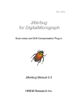
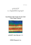
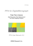
Model 782
ES500W Erlangshen CCD
Camera User’s Guide
Windows 2000/XP
Revision 1.0
March 2005
Quick Start Reference
Follow the steps below to view, acquire and save images.
(1) Prepare Gain reference image (no sample and even
illumination on TEM viewing screen).
Target intensity: 2000 – 25000 and average 4 frames.
(2) Click Start View and search areas of interest in sample.
Camera setting: 2x binning full CCD area
Gain normalized
Check “Auto exposure” (enable)
(3) Focus image.
(4) Click Start Acquire to capture single frame image.
Camera setting:
1x binning full CCD area
Gain normalized
average 4 frames if sample does not drift
Check “auto exposure”
(5) Quick save of acquired images by clicking the icon (
(6) Click icon (
).
) to display image in page layout mode.
(7) To save image in TIFF or JPEG format, choose
SaveDisplayAs… under the File menu.
When prompted, choose:
- Actual resolution
- Include annotations (save scale bar)
- Save As Grey Scale
2
1. Introduction
Model 782 ES500W Erlangshen CCD camera is a performance upgrade from previously well-known
DV300W CCD camera. The ES500W camera incorporated the advanced CCD interline technology
together with a sophisticated CCD electronics design to increase the performance in image quality,
operation speed, and anti-blooming. The ES500W camera also offers background-corrected (gain
normalized) digital streaming video (DSV) output that facilitates remote-microscopy applications.
The purpose of this document is to give user a short and concise explanation on how to operate the
ES500W CCD camera. In particular users will learn how to (1) acquire images; (2) calibrate the
magnifications for the camera; and (3) save images.
2. Software
ES500W camera comes with standard Gatan Microscopy Suite (GMS) software plus digital streaming
video (DSV) plug-in. The software runs on Windows 2000 or XP platform.
To install the software, first install the License file from the GMS License CD. Then run the installer
from the GMS CD. When prompted for Gatan hardware, check “ES500W” and any other optional
software items that come with the system.
3. Acquiring Images
All the necessary software for acquiring images is displayed on the right hand side of
DigitalMicrograph (DM) work environment. It is recommended that the floating windows be arranged
(see next page).
3.1
Prepare dark reference image
ES500W automatically performs automatic dark subtraction. Use “Prepare dark reference” under
the Camera menu to carry out this procedure. Under normal operation conditions, there is no need to
perform frequent operation of Prepare Dark Reference. Once every month may be adequate.
3.2
Prepare gain reference image
Gain variation (contrast observed in image recorded with parallel illumination when there is no
specimen) is an intrinsic property of the CCD camera. It happens to all image recording media
including films.
For digital cameras, it is possible to correct this gain variation live using Gain reference image, which
is prepared before any sample images are viewed or recorded.
3
To prepare Gain reference image, choose, move specimen out of the field of view or completely
remove it from the TEM; evenly spread the illumination across the entire large TEM viewing screen;
insert the camera.
Under the Camera menu, choose Prepare Gain Reference. Set the target intensity to the value
between 2000 – 2500 and set 4 as the number of frames.
The procedure is automatic and gain reference images are recorded for
different binning settings. For higher binning setting, user may be asked to
spread the illumination even more to ensure the target intensity is within the
specified range. If necessary, one can spread the illumination even more by
using smaller spot size.
Gain correction to acquired images is essential to the image quality. Frequent
check and update on gain reference image is advised. To check the usability
of existing gain reference image, remove sample from the field of view and
spread illumination at least to the size of the large TEM viewing screen, make
sure the view mode is set as Gain normalized. Click Start View. If the gain
reference image is good, the observed image should show uniform image
intensities as shown below.
3.3
View LIVE images
Click the button “Start View” in the Camera View palette to view LIVE
images. Check the box of “Auto exposure” to enable it. If Focus loupe is
checked, a small sub-area becomes active. This allows user to focus image
with higher image refresh rate on the computer monitor.
If image intensity flickers, uncheck the box of Auto Survey.
Click the button “Stop View” or press the Space baron the computer key
board to stop the LIVE view.
Click the set up button (
)to check parameter settings.
Recommended parameters:
3.4
-
2x binning, full CCD
-
gain normalized
Acquire images
Once the sample area of interest is located and focus set, click the button “Start Acquire” in the
Camera Acquire palette to acquire a single frame image. To ensure optimum image intensity, check
the box of “Auto exposure” before acquiring the single frame image.
Click the set up button to check parameter settings.
4
Recommended parameters:
-
1x binning, full CCD
-
gain normalized
-
4 frames average if sample does not drift
4. Save images
4.1
Quick save images
DigitalMicrograph software allows acquired images to be quickly saved to a pre-specified file folder
with customized image names.
To set up the Quick save, click on the set up icon (
Numbered tab. The control box is shown below:
) in the Saving palette and click Save
Click the Browse button to specify the directory
folder where all acquired images are to be saved.
File name can be built in two ways. (1) Build
Using Parameter builds image file names using
all or selected names of Specimen, TEM voltage,
TEM magnification, and Operator name (user
specify); (2) Build Using String builds image file
names using a particular text string (user specify).
User can also choose the starting index number for
the quick save.
There are two image formats to choose from as
indicated in the File Content and Format. Image
data can be saved in native Gatan format
(preferred) or other popular format. To save
images in TIFF, JPEG, or Bitmap format (BMP),
click Save Display As and choose the desired format in the pull down list.
Once the Set up is complete, simply click the Quick save button (
4.2
) on the Saving palette.
Page layout format
Images can be saved and printed in page format mode. To display image in the Page layout format
(see below - left), click the Page layout icon (
).
5
It is possible to define a custom page layout. Click on the set up icon (
click Data Bar tab. The control box is shown below (right):
) in the Saving palette and
User can specify what information goes on the Page layout. To add Logo to the page layout, click the
Option button and use the Window browser to locate the logo file. User can also add “Custom text” to
the page layout. “Custom text” refers to text that does not change with each image, for example, the
name of the TEM lab. The Click the Edit button, type the text, and click Add. Click OK to exit.
6
The icon (
(
) is for delete all the text information while image remains in the Page mode. The icon
) adds the text information back to the page.
To define a custom page layout template, click on the text items on the page and arrange them on the
page. Once everything is defined, go to the Edit menu and choose Data Bar -> Use as global
Default (see below).
If needed, user can select Reset Global Data Bar and redefine the page layout template.
5. TEM Session Information
Before starting each TEM session, user can enter
information on sample, operator, microscope, and
electron beam energy (kV) by choosing Global info
under the Microscope menu (see below). The
session information is automatically transferred to
all the acquired images. In page layout mode
(discussed in section 4.2), TEM session information
can be displayed.
7
If the host computer can not communicate with the TEM, user can choose one of the following
regarding the indicated TEM magnification.
(1) Ask User : Always – prompt for magnification every time an image is acquired.
(2) Ask User : Once – prompt for magnification only the first time an image is acquired.
(3) Ask User : Never – never prompt for magnification.
6. Magnification Calibration
Since the CCD camera is installed at different height in the electron beam path from the TEM
photographic film, the magnification displayed on the TEM console does not represent the actual
magnification on the CCD camera. Hence calibration is necessary.
Magnification calibration can be carried out using a standard calibration sample such as the “cross
grating” sample which contains periodic lines with a spacing of 0.463 µm (2160 lines per mm).
Procedure:
(1) Record a full frame CCD image by clicking the Start Acquire button. Under the Microscope
menu, choose Calibrate Image….
(2) Follow the on screen instructions.
(3) A red line will appear on the image.
Position it on a feature of known size.
8
Press OK on the “Calibrate image” window.
(4) Enter the correct distance for the selected feature (for example 10 line pairs of cross grating
sample where the distance = 10 x 0.463µm) in the “Calibration” window and select the units.
(5) Press OK.
(6) Choose YES in the next window to complete
the magnification calibration.
The calibration can be checked on the calibration
table containing pairs of value: the nominal microscope
magnification and the calibrated value. To view the magnification
table:
Select “Mag table” from the Microscope menu. It is recommended to
save the magnification table.
The first column represents the nominal TEM magnification and the
second column is the actual magnification at the CCD. For ES500W
camera, the typical magnification factor (defined as “TEM mag/actual
mag”) is about 7-10%. This is due to the fact that the camera is
installed above the TEM viewing chamber and the optical lens in the
CCD camera.
It should be noted that magnification calibration is kV dependent. If
the magnification is calibrated for a particular kV value and image is
acquired at a different kV value, a warning dialog will appear (see
below). If slight change in magnification due to change in kV is
acceptable, choose “Use the calibrations at the nearest HT” option.
If in view mode and one chooses “Continue without mag
calibration”, please make sure to check the box of “Don’t warn me (at this setting) anymore”.
9
7. Digital Streaming Video (DSV)
The software for ES500W CCD camera includes Digital Streaming Video (DSV) software module.
This software enables DigitalMicrograph to generate a continuous digital streaming video signal from
any image window in DigitalMicrograph. Although the DSV module does not directly produce digital
movie (AVI or MPEG), the signal generated by DSV can be viewed or recorded by any software
applications that require streaming video input such as Microsoft NetMeeting, or other commercial
video Capture/Edit software.
Since images in DigitalMicrograph can be gain normalized (background corrected), DSV output
provides the highest video quality (digital) free from detector artifact such as shading or gain variation.
Hence DSV is the best way to view and study dynamic events (in-situ) in TEM.
User has the option to select the size of the streaming video. Annotations such as scale bar can also be
captured in the streaming video.
The set up the DSV, click the set up icon (
) on Digital Streaming Video (see below).
User can specify the Image Capture Window
and the Video Image Format from the pull down
menus. To add a new video format, click the Add… button and enter a new format. To include scale
bar in the digital video stream, check the box of Include Annotations.
The value for Interval (ms) refers to the time DigitalMicrograph software waits before generating next
video frame. It is recommended to use 60ms.
Depending on the computer specification, user may find the computer slowing down when DSV is
activated.
To Start the digital video stream, click the Start Video button on the DSV palette on the desk top of
DigitalMicrograph (above).
Digital video stream (DSV) must be viewed by Application software that accepts DSV as input signal.
Many commercial software uses DSV to record movie clips.
Below shows an example of using Microsoft NetMeeting to view the DSV stream.
10
Start NetMeeting. Go to Tools -> Options… Click on the Video tab. In the Video camera
properties pull down menu, choose DVVideo Capture. Then click OK.
Next click the Start video button (
) to see the DSV signal.
11