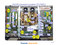
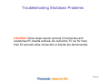
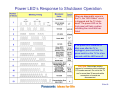
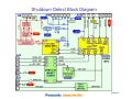
1
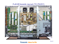
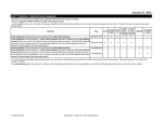
New 7 blinks
Troubleshooting
Procedure
Revised Troubleshooting Handbook
2009-Plasma HD and FHD TV (12th Generation)
Applies to models:
TC-P42X1
TC-P50X1
TC-P42C1
TC-P50C1
TC-P42S1
TC-P46S1
TC-P50S1
TC-P54S1
TC-P42U1
TC-P46U1
TC-P50U1
TC-P42G10
TC-P46G10
TC-P50G10
TC-P54G10
TC-P42G15
TC-P46G15
TC-P50G15
TC-42PS14
TC-50PS14
TC-P50V10
TC-P54V10
Model TC-P42PX1
Panasonic Service and Technology Company
National Training
TTG090507CP\REV091117
Slide #1
Prepared by
Cesar Perdomo
Panasonic Service and Technology Company
National Training
"HDMI, the HDMI logo and High-Definition Multimedia Interface are trademarks or registered trademarks of HDMI Licensing LLC.“
Copyright © 2009 by Panasonic Service and Technology Company
All rights reserved. Unauthorized copying and distribution is a violation of law.
Warning
This service information is designed for experienced repair technicians only and is not designed for use by the
general public. It does not contain warnings or cautions to advise non-technical individuals of potential dangers in
attempting to service a product. Products powered by electricity should be serviced or repaired only by
experienced professional technicians. Any attempt to service or repair the product or products dealt with in this
service information by anyone else could result in serious injury or death.
Slide #2
Table of Content
Subject
Table of Contents
Introduction
HD Boards Layout (TC-P42X1)
Full HD Boards Layout (TC-42PS1)
Full-HD Connector’s Location (TC-P42S1)
Troubleshooting Shutdown Problems
Power LED’s Response to Shutdown Operation
Shutdown Detect Block Diagram
HD Panel Drive SOS Detect Block Diagram (TC-P42X1)
Full-HD Panel Drive SOS Detect Block Diagram (TC-P42S1)
Power LED’s Response to Connectors Removal (42” HD)
Power LED’s Response to Connectors Removal (42” HD)
Power LED’s Response to Connectors Removal (50” HD)
Power LED’s Response to Connectors Removal (Full HD)
Power LED’s Response to Connectors Removal (Full HD)
SU and SD board Isolation Procedure
Procedure to Isolate Bothe SU and SD at the Same Time
Procedure to Isolate Bothe SU and SD at the Same Time
SU Board Isolation Procedure
SD Board Isolation Procedure
How to Easily Gain Access to the SS board
Front Cabinet Removal
SU and SD Boards Isolation Procedure
SU, SD, and SC Boards Resistance Test Procedure
SU Board Resistance Test (All Models)
SD Board Resistance Test (All Models Except TC-50PX14, TC-P50X1, TC-P50C1)
SD Board Resistance Test ( Models: TC-50PX14, TC-P50X1, TC-P50C1)
SC Board Resistance Test (All Models Except TC-50PX14, TC-P50X1, TC-P50C1)
SC Board Resistance Test ( Models: TC-50PX14, TC-P50X1, TC-P50C1)
1 Blink Error Code (All Models)
2 Blinks Error Code (All Models)
2 Blinks Error Code (All Models)
3 Blinks Error Code (All Models)
4 Blinks Error Code (All Models)
Slide
3
4
5
6
7
8
9
10
11
12
13
14
15
16
17
18
19
20
21
22
23
24
25
26
27
28
29
30
31
32
33
34
35
36
Subject
5 Blinks Error Code
5 Blinks Error Code (All Models)
5 Blinks Error Code (All Models)
5 Blinks Error Code Continue
6 Blinks Error Code (HD Models)
6 Blinks Error Code (42” HD Models) Flowchart
6 Blinks Error Code (50” HD Models) Flowchart
6 Blinks Error Code (Full-HD Models)
6 Blinks Error Code (Full-HD Models) Flowchart
7 Blinks Error Code
7 Blinks Error Code
7 Blinks Error Code
7 Blinks Error Code
8 Blinks Error Code (HD Models)
8 Blinks Error Code (HD Models)
8 Blinks Error Code (HD Models) Flowchart
8 Blinks Error Code (Full-HD Models)
8 Blinks Error Code (Full-HD Models)
8 Blinks Error Code (Full-HD Models) Flowchart
9 Blinks Error Code
10 Blinks Error Code (HD Models)
10 Blinks Error Code (HD Models) Flowchart
10 Blinks Error Code (Full-HD Models)
10 Blinks Error Code (Full-HD Models) Flowchart
11 Blinks Error Code (Full-HD Models)
12 Blinks Error Code (Full-HD Models)
13 Blinks Error Code
No Power Flowchart
Service Mode
Self Check
Reset Procedure
SOS History
Diagnostic Method for Troubleshooting PDP Television
Picture Problem Solution
The End
Slide
37
38
39
40
41
42
43
44
45
46
47
48
49
50
51
52
53
54
55
56
57
58
59
60
61
62
63
64
65
66
67
68
69
70
71
Slide #3
Introduction
1. Basic concept of how to determine the defective board
1) Verification of voltages
Normally, when there is a power problem, shutdown occurs immediately.
So, to resolve a power problem, voltage checks are necessary before shutdown.
2) Check if the power comes up after disconnecting the board under suspicion.
If power comes up (*) after disconnecting a board, the board is defective.
(*) “Power comes up” equals “no shutdown”.
2. Troubleshooting Video and Audio problems
3. Examples of video problems
4. Adjustment after PCB exchange
1) After exchanging the following boards, voltage adjustment is required.
P board, SC board, SS board => Please refer to the “Service Manual”.
Slide #4
HD boards Layout (TC-P42X1)
Slide #5
Full-HD boards Layout (TC-P42S1)
Slide #6
Full-HD Connector’s Location (TC-P42S1)
Slide #7
Troubleshooting Shutdown Problems
CAUTION: Some steps require removal of connectors and
sometimes PC boards removal. Do not let the TV run for more
than 30 seconds while connectors or boards are disconnected.
Slide #8
Power LED’s Response to Shutdown Operation
When an abnormality occurs in
the TV, the “SOS Detect” circuit
is triggered and the TV shuts
down. The power LED on the
front panel will flash a pattern
indicating the circuit that has
failed.
If the power LED continues to
blink even after the TV is
unplugged, press and hold the
power switch on the TV for a few
seconds until the LED turns off.
CAUTION: Some steps require
removal of connectors and sometimes
PC boards removal. Do not let the TV
run for more than 30 seconds while
connectors or boards are
disconnected.
Slide #9
Shutdown Detect Block Diagram
Slide #10
HD Panel Drive SOS Detect Block Diagram (TC-P42X1)
Slide #11
Full-HD Panel Drive SOS Detect Block Diagram (TC-P42S1)
Slide #12
Power LED’s Response to Connectors Removal (42” HD Models)
HD Models
Do not remove any connectors from any of
the PC boards unless instructed to do so.
CAUTION: Some steps require
removal of connectors and
sometimes PC boards removal.
Do not let the TV run for more
than 30 seconds while
connectors or boards are
disconnected.
CAUTION: The TV power should not be
turned on while SC2 is disconnected. This
could damage the SS board.
Model: TC-P42X1
Connector
Connector
Connector
A20
Result
OK
Unplugged
A31
SOS 6 Blinks
Unplugged
A32
Unplugged
A20
A31
Unplugged
Unplugged
SOS 6 Blinks
OK
A20
A32
Unplugged
Unplugged
A31
A32
Unplugged
Unplugged
A20
A31
A32
Unplugged
Unplugged
Unplugged
OK
SOS 6 Blinks
TV Stays On With Black Screen
Slide #13
Power LED’s Response to Connectors Removal (42” HD Models)
42”HD Models
CAUTION: The TV power should not be
turned on while SC2 is disconnected. This
could damage the SS board.
CAUTION: Some steps require
removal of connectors and
sometimes PC boards removal.
Do not let the TV run for more
than 30 seconds while
connectors or boards are
disconnected.
Do not remove any connectors
from any of the PC boards
unless instructed to do so.
Model: TC-P42X1 (SS Board Isolation)
Model: TC-P42X1 (SC Board Isolation)
Connector
Connector
Connector
SC2
Connector
On SS
board
Result
SC3
SC20
Unplugged
SC2
SC3
Unplugged
Unplugged
Unplugged
OK
SOS 7 Blinks
SC20
SC2
Unplugged
SC3
SC20
Unplugged
Unplugged
Connector
SOS 8 Blinks
SOS 8 Blinks
Result
SOS 6 Blinks
Unplugged
SS3
SOS 6 Blinks
Unplugged
SOS 6 Blinks
Unplugged
Connector
SS11
SOS 7 Blinks
Unplugged
Connector
SS23
Unplugged
SS11
SS3
Unplugged
Unplugged
SOS 6 Blinks
SS11
SS23
Unplugged
Unplugged
SS3
SS23
Unplugged
Unplugged
SS11
SS3
SS23
Unplugged
Unplugged
Unplugged
SC2
SC3
SC20
SS11
Unplugged Unplugged Unplugged Unplugged
SC20
SC2
SS11
Unplugged Unplugged
Unplugged
SS11
SC20
Unplugged Unplugged
OK
SOS 6 Blinks
SOS 6 Blinks
SOS 6 Blinks
OK
OK
OK
Slide #14
Power LED’s Response to Connectors Removal (50” HD Models)
50”HD Models
CAUTION: The TV power should not be
turned on while SC2 is disconnected. This
could damage the SS board.
CAUTION: Some steps require
removal of connectors and
sometimes PC boards removal.
Do not let the TV run for more
than 30 seconds while
connectors or boards are
disconnected.
Do not remove any connectors
from any of the PC boards
unless instructed to do so.
Model: TC-P42X1 (SS Board Isolation)
Model: TC-P50X1 (SC Board Isolation)
Connector
On C1
board
Connector
Connector
Connector
On SS
board
SC3
Result
SC20
SC3
SC20
SS11
Unplugged
Unplugged
Unplugged
C10
SC20
SS11
Unplugged
Unplugged
Unplugged
Connector
SOS 8 Blinks
OK
SC3
SC20
SS11
Unplugged Unplugged Unplugged
SC20
SS11
Unplugged Unplugged
SC20
SS11
Unplugged Unplugged
Result
SOS 6 Blinks
Unplugged
SS3
SOS 6 Blinks
Unplugged
SOS 6 Blinks
Unplugged
Connector
SS11
SOS 6 Blinks
Unplugged
Connector
SS23
Unplugged
SS11
SS3
Unplugged
Unplugged
OK
SOS 6 Blinks
SS11
SS23
Unplugged
Unplugged
SS3
SS23
Unplugged
Unplugged
SS11
SS3
SS23
Unplugged
Unplugged
Unplugged
SOS 6 Blinks
SOS 6 Blinks
SOS 6 Blinks
SOS 6 Blinks
SOS 6 Blinks
SOS 6 Blinks
Slide #15
Power LED’s Response to Connectors Removal (Full HD Models)
Full HD Models
Model: TC-P42S1
Do not remove any connectors from any of
the PC boards unless instructed to do so.
Connector
Connector
Connector
A33
SOS 6 Blinks
Unplugged
Left Half of Screen is OK (Right Side is
Black)
A31
Unplugged
CAUTION: Some steps require
removal of connectors and sometimes
PC boards removal. Do not let the TV
run for more than 30 seconds while
connectors or boards are
disconnected.
Results
A32
Unplugged
A33
A31
Unplugged
Unplugged
SOS 6 Blinks
SOS 6 Blinks *
A33
A32
Unplugged
Unplugged
A31
A32
Unplugged
Unplugged
A33
A31
A32
Unplugged
Unplugged
Unplugged
OK
SOS 6 Blinks
TV Stays On With Black Screen
Slide #16
Power LED’s Response to Connectors Removal (Full HD Models)
Full HD Models
CAUTION: Some steps require removal of connectors and
sometimes PC boards removal. Do not let the TV run for
more than 30 seconds while connectors or boards are
disconnected.
Do not remove any connectors from any of
the PC boards unless instructed to do so.
Model: TC-P42S1 Connectors Combination between SS and SC Boards)
SC Board
SS Board
Result
Model: TC-P42S1 (SS Board Isolation)
Connector
Connector
Connector
SC20
Unplugged
SC2
Unplugged
SC20
SC2
Unplugged
Unplugged
Connector
Results
Connector
SS11
SS33
Unplugged
SS11
SS33
Unplugged
Unplugged
Connector
SS11
SC2
Unplugged
Unplugged
SS11
SC20
7 Blinks *
Unplugged
Unplugged
SS11
SC2
SC20
6 Blinks *
Unplugged
Unplugged
Unplugged
Result
OK
Unplugged
Connector
6 Blinks *
Model: TC-P42S1 (SS Board Isolation)
Connector
Connector
OK
OK
SS11
SS33
SC2
Unplugged
Unplugged
Unplugged
7 Blinks
SS11
SS33
SC20
Unplugged
Unplugged
SS11
SS33
SC2
SC20
Unplugged
Unplugged
Unplugged
Unplugged
SS33
SC2
Unplugged
6 Blinks
7 Blinks
Unplugged
Unplugged
6 Blinks
6 Blinks
6 Blinks
7 Blinks
SS33
SC20
Unplugged
Unplugged
SS33
SC2
SC20
Unplugged
Unplugged
Unplugged
6 Blinks
6 Blinks
Slide #17
SU and SD Boards Isolation Procedure
If the power LED continues to blink even after the TV is unplugged, press and hold the power
switch on the TV for a few seconds until the LED turns off.
Beginning last year (2008), the plasma TV
are designed to shutdown if either the SU or
SD board is disconnected.
Disconnecting either board causes the unit
to shutdown and the power LED to blink 7
times.
Unplugging any of the connectors
SC41/SU41, SU11/SD11, and
SC42/SD42, opens the interlocked
connection between VF_GND and CHA on
the SC board. This floats point “CHA”
triggering the SOS7 detect circuit. This
outputs a high to the A board through
connector SC20 triggering shutdown.
A new SC test fixture (Jig) can be used when
the SU and SD boards are isolated. The jig is a
small connector with a jumper between pin 1
and pin 2. The part number is TZSC09187.
It plugs into connector SC50 on the SC board.
Slide #18
Procedure to Isolate both SU & SD at the Same Time
If the power LED continues to blink even after the TV is unplugged, press and hold the power
switch on the TV for a few seconds until the LED turns off.
To isolate the SU and SD boards at the same time is not necessary to remove any
of the boards:
•
Remove the 4 VF_GND screws (2 on the SU board and 2 on the SD board).
•
Unplug connectors SC41, SC46, and SC42 on the SC board.
•
Place the SC jig cable (TZSC09187) between pins 1 and 2 of connector SC50 on
•
the SC board.
Note: If the SC jig is not available,
install a jumper between pins 1 and 2
of connector SC50 on the SC board.
(Remove the jig or the jumper after
completing isolation procedure).
When this is done, the display is
completely black (No picture)
Note: This procedure could be useful
when troubleshooting 7 blinks
problems.
Slide #19
Procedure to Isolate both SU & SD at the Same Time
If the power LED continues to blink even after the TV is unplugged, press and hold the power
switch on the TV for a few seconds until the LED turns off.
Slide #20
SU Board Isolation Procedure
If the power LED continues to blink even after the TV is unplugged, press and hold the power
switch on the TV for a few seconds until the LED turns off.
To isolate the SU board:
1.
Remove the 2 VF_GND screws on the
SU board only.
2.
Unplug connector SC41 on the SC
board and SU11 on SU board.
3.
Place SC jig cable ZSC09187)between
pins 1 and 2 of connector SC50 on the
SC board.
Note: If the SC jig is not available, install a
jumper between pins 1 and 2 of
connector SC50 on the SC board.
(Remove the jig or jumper after
completing isolation procedure)
Note: This procedure could be useful when
troubleshooting 7 blinks problems.
Slide #21
SD Board Isolation Procedure
If the power LED continues to blink even after the TV is unplugged, press and hold the power
switch on the TV for a few seconds until the LED turns off.
To isolate the SD board:
1.
Remove the 2 VF_GND screws on the
SD board only.
2.
Unplug connector SC42/SU42,
SC46/SD46, and SU11/SD11 from the
SD board.
3.
Place SC jig cable (TZSC09187)
between pins 1 and 2 of connector
SC50 on the SC board.
Note: If the SC jig is not available, install a
jumper between pins 1 and 2 of connector
SC50 on the SC board. (Remove the jig or
jumper after completing isolation procedure)
Note: This procedure could be useful when
troubleshooting 7 blinks problems.
Slide #22
How to Easily Gain Access to the SS board
SCREW
SCREW
SCREW
1
Remove the 3 screws that hold
the A board assembly in place
2
Let the A board assembly rest on the speaker’s
magnet to gain access to the SS board
Slide #23
Front Cabinet Removal
Remove the rear cover.
Remove the 4 screws holding
the front panel in place.
Remove the cables from the
speakers.
Remove the screws from the
speakers (2 each).
Remove the speakers.
Remove the front cabinet.
Note: To remove the front
cabinet, pull the bottom
slightly forward and then lift it
up.
Slide #24
SU and SD Boards Visual Inspection
Check the ICs on the SU and SD boards for blown hole on the
surface.
Note: In some models it is not possible to check if these ICs are
blown because they use surface-mount heat sinks that are glued to
the surface of the ICs.
This is an
example of what
a blown IC looks
like
Slide #25
SU,SD, and SC Boards Resistance Test Procedure
SU,SD, and SC Boards Resistance
Test Procedure
Note: The result of the resistance test determine if the boards are bad, but it does not
determine if they are 100% good. For this reason, after performing a resistance test, we
need to further check the boards that check OK using another procedure.
Slide #26
SU Board Resistance Test (All Models)
Preparation:
Disconnect AC Power prior to making any disconnection or connection.
Wait at least 2 minutes before the removal of any connector.
Note: If the power LED continues to blink even after the TV is unplugged, press and hold the power
switch on the TV for a few seconds until the LED turns off.
Unplug connector SU41 and SU11. Remove the 2 floating ground screws from the SU board.
Procedure:
Using a digital meter
measure the resistance
between VF-ground
(Floating ground) and
pin 2 of connector SU41
on the SU board.
The normal resistance
should be approximately
2.1Mega-ohms.
Note: A low resistance
reading indicates a
defective SU board.
Slide #27
SD Board Resistance Test (All Models, Except TC-50PX14, TC-P50C1, TC-P50X1)
Preparation:
Disconnect AC Power prior to making any disconnection or connection.
Wait at least 2 minutes before the removal of any connector.
Note: If the power LED continues to blink even after the TV is unplugged, press and hold the power
switch on the TV for a few seconds until the LED turns off.
Unplug connectors SD42, SD46 and SD11. Remove the 2 floating ground screws from the SD board.
Procedure:
Using a digital meter,
measure the resistance
between VF-ground
(Floating ground) and
pin 9 of connector SD42
on the SD board.
The normal resistance
should be approximately
2.1Mega-ohms.
Note: A low resistance
reading indicates a
defective SD board.
Slide #28
SD Board Resistance Test ( Models: TC-50PX14, TC-P50C1, TC-P50X1)
Preparation:
Disconnect AC Power prior to making any disconnection or connection.
Wait at least 2 minutes before the removal of any connector.
Note: If the power LED continues to blink even after the TV is unplugged, press and hold the power
switch on the TV for a few seconds until the LED turns off.
Unplug connectors SD42, SD46 and SD11. Remove the 2 floating ground screws from the SD board.
Procedure:
Using a digital meter,
measure the resistance
between VF-ground
(Floating ground) and
pin 1 of connector SD42
on the SD board.
The normal resistance
should be approximately
2.1Mega-ohms.
Note: A low resistance
reading indicates a
defective SD board.
Slide #29
SC Board Resistance Test (All Models, Except TC-50PX14, TC-P50C1, TC-P50X1)
Preparation:
Disconnect AC Power prior to making any disconnection or connection.
Wait at least 2 minutes before the removal of any connector.
Note: If the power LED continues to blink even after the TV is unplugged, press and hold the power
switch on the TV for a few seconds until the LED turns off.
Unplug connectors SD42, SD46, SU41 and SD11. Out of all 4 floating ground screws on the SU and
SD boards, remove 3 and leave only one in.
Procedure:
Using a digital meter measure the
resistance between the VF-ground screw
(Floating ground) and pin 3 of connector
SC42.
Also measure the resistance between
the VF-ground screw (Floating ground)
and pin 5 of connector SC42 on the SC
board.
The normal resistance for pin 3 is
approximately 2.9Kilo-ohms and approx.
5.7Kilo-ohms for pin 5.
Note: A low resistance reading indicates
a defective SC board.
Slide #30
SC Board Resistance Test ( Models: TC-50PX14, TC-P50C1, TC-P50X1)
Preparation:
Disconnect AC Power prior to making any disconnection or connection.
Wait at least 2 minutes before the removal of any connector.
Note: If the power LED continues to blink even after the TV is unplugged, press and hold the power
switch on the TV for a few seconds until the LED turns off.
Unplug connectors SD42, SD46, SU41 and SD11. Out of all 4 floating ground screws on the SU and
SD boards, remove 3 and leave only one in.
Procedure:
Using a digital meter measure the
resistance between the VF-ground screw
(Floating ground) and pin 5 of connector
SC42.
Also measure the resistance between
the VF-ground screw (Floating ground)
and pin 7 of connector SC42 on the SC
board.
The normal resistance for pin 5 is
approximately 2.9Kilo-ohms and approx.
5.7Kilo-ohms for pin 7.
Note: A low resistance reading indicates
a defective SC board.
Slide #31
1 Blink Error Code
If the power LED continues to blink even after the TV is unplugged, press and hold the power
switch on the TV for a few seconds until the LED turns off.
Trouble Mode
Defective Board
Communication Error
A, P, Loose connections
Warning: Disconnect AC Power prior to
making any disconnection or connection.
Make sure that connectors P25 and D25 are properly seated
Start Here
Plug in the TV
No
Is there 5V at
pin 9 of
connector
P25/A25?
Yes
Unplug in the TV
Replace the A
board
No
Replace the P
board
Is there
continuity between
pin 9 of connector
P25 and pin 5 of
connector P7 on
the P board?
Yes
Reseat P25/A25 or
Replace the cable
Slide #32
2 Blinks Error Code (All Models)
If the power LED continues to blink even after the TV is unplugged, press and hold the power
switch on the TV for a few seconds until the LED turns off.
Trouble Mode
Defective Board
P15V
A, SC, SS
Warning: Disconnect AC Power prior to
making any disconnection or connection.
These 3 conditions can cause the TV to shutdown and the power LED to blink 2 times
1. Missing P15V
2.
A short of the P15V
3.
Wrong diagnostic by the A board
Slide #33
2 Blinks Error Code (All Models)
If the power LED continues to blink even after the TV is unplugged, press and hold the power
switch on the TV for a few seconds until the LED turns off.
Start Here
Unplug the TV and check the resistance between pin 1 of connector P6 and ground (Chassis)
No
Plug in the TV and turn it on. Measure
the voltage at pin 1 of connector P6
No
Is there
15V
present?
Reconnect P25 and measure the
resistance between pin 1 of
connector P6 and ground (Chassis)
No
Replace
The A board
Is there a
short
circuit?
Unplug connectors P6, P11, and P25 on the P
board. Measure the resistance between pin 1 of
connector P6 and ground (Chassis)
Yes
No
Yes
Replace
The A board
Replace
The P board
Is there a
short
circuit?
Yes
Reconnect P11 and measure the
resistance between pin 1 of
connector P6 and ground (Chassis)
No
Disconnect SC20 on the SC board
and measure the resistance between
pin 1 of connector P6 and ground
(Chassis
Is there a
short
circuit?
Yes
Is there a
short
circuit?
Replace
The P board
Yes
Replace
The SS board
No
Replace
The SC board
Is there a
short
circuit?
Yes
Replace
The A board
Slide #34
3 Blinks Error Code
If the power LED continues to blink even after the TV is unplugged, press and hold the power
switch on the TV for a few seconds until the LED turns off.
Trouble Mode
Defective Board
3.3V down SOS
A Board
Warning: Disconnect AC Power prior to
making any disconnection or connection.
Start Here
Replace the A board
Slide #35
4 Blinks Error Code
If the power LED continues to blink even after the TV is unplugged, press and hold the power
switch on the TV for a few seconds until the LED turns off.
Trouble Mode
Defective Board
Power Supply SOS
Primarily P board or possible A board
TC-P42G10
TC-P46G10
TC-50G10
Warning: Disconnect AC Power prior to
making any disconnection or connection.
TC-P54G10
All other 2009 Models
Start Here
Disconnect the TV. Disconnect
P2 and P11 on the P board
Measure the resistance between
pin 1 of connector SS11 on the
SS board and ground (Chassis).
Yes
Is there a
short to
ground?
No
Yes
Start Here
Does the power
supply
makes a “chirp”
noise at plug in?
No
Measure the resistance between
pin 1 of connector SC2 on the SC
board and ground (Chassis).
Replace
the SS board
Turn the TV on
Yes
Yes
Replace
the SC board
Is there a
short to
ground?
No
P Board
Is pin
12 of CN P25 on
the P board high
before the TV
shuts down?
No
A Board
Replace
the P board
Slide #36
5 Blinks Error Code
If the power LED continues to blink even after the TV is unplugged, press and hold the power
switch on the TV for a few seconds until the LED turns off.
Trouble Mode
Defective Board
5V SOS
P, C, SC, SS board or Panel
Warning: Disconnect AC Power prior to
making any disconnection or connection.
These 4 conditions can cause the TV to shut down and the power LED to blink 5 times
1.
Missing P5V
2.
A short of the P5V
3.
A short of the Vda line
(Note: missing Vda from the
P board does not cause 5
blinks)
4.
Wrong diagnostic by the A
board
Slide #37
5 Blinks Error Code (All Models)
If the power LED continues to blink even after the TV is unplugged, press and hold the power
switch on the TV for a few seconds until the LED turns off.
Trouble Mode
Defective Board
5V SOS
P, C, A,SC, SS board or Panel
TC-P42G10
TC-P46G10
Warning: Disconnect AC Power prior to
making any disconnection or connection.
TC-50G10
TC-P54G10
All other 2009 Models
Start Here
Disconnect the TV. Disconnect
P2 and P11 on the P board
Measure the resistance between
pin 1 of connector SS11 on the
SS board and ground (Chassis).
Yes
Replace
the SS board
Is there a
short to
ground?
Yes
Replace
the SC board
No
Is there a
short to
ground?
Yes
Start Here
Does the power
supply
makes a “chirp”
noise at plug in?
Measure the resistance between
pin 1 of connector SC2 on the SC
board and ground (Chassis).
No
Disconnect the TV. Measure the resistance
between pin 1 of connector P35 on the P
board and ground (Chassis).
Yes
No
Panel
Replace
the P board
Note: Even though it
does not happen often,
the 5 blinks shutdown
can also be caused by
one of the C boards
Is there a
short to
ground?
No
Proceed to more extensive troubleshooting
of the slides that follow.
Slide #38
5 Blinks Error Code (All Models)
If the power LED continues to blink even after the TV is unplugged, press and hold the power
switch on the TV for a few seconds until the LED turns off.
Start Here
Use a volt-meter and place the positive probe on pin 5 of connector P25 on the P board
while the negative probe is grounded. Plug in the TV and turn it on
Replace
the A board
Yes
Is
there
5V?
No
Disconnect the TV and measure the
resistance between pin 5 of connector P25 on
the P board and ground (Chassis).
Yes
Is there a
short to
ground?
Replace
the P board
No
No
Yes
Disconnect P25 on the P board. Measure the
resistance between pin 5 of connector P25 on
the P board and ground (Chassis).
Reconnect P25 and disconnect SC20 on
the SC board. Measure the resistance
between pin 5 of connector P25 on the P
board and ground (Chassis).
Is there a
short to
ground?
Replace
the P board
Yes
No
Is there a
short to
ground?
Reconnect SC20 and disconnect SS23 (HD models)/SS33 (FullHD models) on the SS board. Measure the resistance between
pin 5 of connector P25 on the P board and ground (Chassis).
Yes
Go to the
next slide (A)
Is there a
short to
ground?
Disconnect SC46 and reconnect
SC20 on the SC board. Measure
the resistance between pin 5 of
connector P25 on the P board and
ground Chassis).
Yes
No
Replace
the SS board
Replace
the SC board
Is there a
short to
ground?
No
Replace
the SD board
Slide #39
5 Blinks Error Code Continue
If the power LED continues to blink even after the TV is unplugged, press and hold the power
switch on the TV for a few seconds until the LED turns off.
Note B: The C board can be checked individually.
Reconnect the ribbon cables from the A board (A31, A32,
and A20 for HD models/A33). Disconnect the flex cables
between the panel and the C boards tested. Measure the
resistance between pin 5 of connector P25 on the P
board and ground (Chassis). If there is still a short circuit,
change the C board.
Continue from the
previous slide (A)
Reconnect SS23/SS33 and disconnect A31, A32, and A20
for HD models/A33 on the A board. Measure the resistance
between pin 5 of connector P25 on the P board and ground
(Chassis).
Yes
Replace
the A board
Is there a
short to
ground?
No
Check the C boards (See Note: B)
If the C boards are ok, replace
the Panel
Slide #40
6 Blinks Error Code (HD Models)
If the power LED continues to blink even after the TV is unplugged, press and hold the power
switch on the TV for a few seconds until the LED turns off.
Trouble Mode
Defective Board
CAUTION: The TV power should not be turned on while
SC2 is disconnected. This could damage the SS board.
SC Energy Recovery Circuit SC, SS, A, SU,SD, and Loose connections
Warning: Disconnect AC Power prior to making any
disconnection or connection.
LIST OF MODELS:
TC-P42X1
TC-P42C1
TC-42PX14
TC-P50X1
TC-P50C1
TC-50PX14
Slide #41
6 Blinks Error Code (42” HD Models) Flowchart
If the power LED continues to blink even after the TV is unplugged, press and hold the power
switch on the TV for a few seconds until the LED turns off.
LIST OF MODELS:
TC-P42X1
TC-P42C1
CAUTION: The TV power should not be turned on while
SC2 is disconnected. This could damage the SS board.
TC-42PX14
Start Here
Verify that all the cables plugged in to the SC and SS boards are properly seated. Also check the ribbon cables and connectors on the A
and C boards. Unplug the TV and disconnect connector SC20 on the SC board. Plug in the TV and turn it on
Yes
Unplug the TV and reconnect
connectors SC20. (Follow the
SU/SD boards isolation procedure
shown on slides 17~19). Plug in
the TV and press the power
switch
Yes
Does the
TV power
up and
stay on?
Does the
TV power
up and
stay on?
6 times
Replace
the SS board
No
8 times
No
Did the
number of
blinks
change?
Yes
10 times
Replace
the A board
No
Unplug the TV and with SC20 still
disconnected, disconnect SS11 on
the SS board. Plug in the TV and
turn it on.
6 times
8 times
Replace
the SS and
A boards
The SU or/and the SD Boards
can be defective. Follow
procedure on slides 17~21 to
determine which of the 2 boards
is defective.
Yes
10 times
Replace
the SC board
Replace
the A board
Is the power
LED still
blinking?
No
Replace
the SS and SC
boards
Slide #42
6 Blinks Error Code (50” HD Models) Flowchart
If the power LED continues to blink even after the TV is unplugged, press and hold the power
switch on the TV for a few seconds until the LED turns off.
LIST OF MODELS:
TC-P50X1
TC-P50C1
TC-50PX14
CAUTION: The TV power should not be turned on while
SC2 is disconnected. This could damage the SS board.
Start Here
Verify that all the cables plugged in to the SC and SS boards are properly seated. Also check the ribbon cables and connectors on the A and C
boards. Unplug the TV and disconnect connector SC20 on the SC board. Plug in the TV and turn it on
6 times
No
Unplug the TV and disconnect
connector SC20 on the SC board,
SS11 on the SS board and C10 on the
C1 board. Plug in the TV and turn it on
Yes
Is the power
LED still
blinking?
No
Did the
number of
blinks
change?
Yes
Replace
the SS board
8 times
10 times
Unplug the TV and reconnect
connectors SC20, SS11, and C10.
(Follow the SU/SD boards
isolation procedure shown on
slides 17~19). Plug in the TV and
press the power switch
Replace
the A board
NOTE: The SS board may had just
become damaged (Shorted Vsus).
Unplug the TV. Keep SC20
disconnected and disconnect connector
SS11 on the SS board and C10 on the
C1 board. Plug in the TV and turn it on
Yes
Yes
The SU or/and the SD Boards can be
defective. Follow procedure on slides
17~21 to determine which of the 2 boards
is defective.
Does the
TV power
up and
stay on?
No
Replace
the SC board
Replace
the SS and
A boards
Is the
power
LED still
blinking?
No
Replace
the SS and
SC boards
Slide #43
6 Blinks Error Code (Full-HD)
If the power LED continues to blink even after the TV is unplugged, press and hold the power
switch on the TV for a few seconds until the LED turns off.
Trouble Mode
Defective Board
SC Energy Recovery Circuit SC, A, SU,SD, and Loose connections
Warning: Disconnect AC Power prior to
making any disconnection or connection.
LIST OF
MODELS:
TC-P42S1
TC-P42G10
TC-P42U1
TC-P42U1
TC-42PS14
TC-P46S1
TC-P46G10
TC-P46U1
TC-P50S1
TC-P50G10
TC-P50U1
TC-P50V10
TC-50PS14
TC-P54S1
TC-54G10
Slide #44
6 Blinks Error Code (Full-HD Models) Flowchart
If the power LED continues to blink even after the TV is unplugged, press and hold the power
switch on the TV for a few seconds until the LED turns off.
LIST OF MODELS
TC-P42S1
TC-P42G10
TC-P42U1
TC-P42U1
TC-42PS14
TC-P46S1
TC-P46G10
TC-P46U1
TC-P50S1
TC-P50G10
TC-P50U1
TC-P50V10
TC-50PS14
TC-P54S1
TC-54G10
Start Here
Verify that all the cables plugged in to the SC and SS boards are properly seated. Also check the ribbon cables and connectors on the A and C
boards. Unplug the TV and disconnect connector SC20 on the SC board and the ribbon cable between connector C10 on the C1 board and
connector C20 of the C2 board. Plug in the TV and turn it on
Yes
8 blinks
Unplug the TV and reconnect connector SC20 and
the ribbon cable between the C boards. Disconnect
connector SS33 on the SS board. Plug in the TV
and press the power switch
No
Is the
power LED
still
blinking?
Did the
number of
blinks
change?
No
6 blinks
Unplug the TV and reconnect connector SS33 on
the SS board. (Follow the SU/SD boards isolation
procedure shown on slides 17~19). Plug in the TV
and press the power switch
Yes
6 blinks
Yes
8 blinks
Replace the SS
Replace
the A board
Replace the A
board
The SU board or/and the SD board
can be defective. Follow
procedure on slides 17~21 to
determine which of the 2 boards
is defective.
Does the
TV power
up and
stay on?
No
Replace
the SC board
Slide #45
7 Blinks Error Code (1 of 4)
Trouble mode
Defective Boards (Possibility)
SC Floating Section SOS
SU, SD, SC, A, P, & Panel
LIST OF
MODELS:
Warning: Disconnect AC Power prior to
making any disconnection or connection.
All 2009 Models
Preparation:
Disconnect AC Power prior to making any disconnection or connection.
Wait at least 2 minutes before the removal of any connector.
Note: If the power LED continues to blink even after the TV is unplugged, press and hold the power switch
on the TV for a few seconds until the LED turns off.
Remove the front cabinet and expose the panel to a bright light for a thorough visual inspection. Check for
cracks and blown pixels or any other abnormalities.
Check the ICs on the SU and SD boards for blown hole on the surface.
Note: In some models it is not possible to check if these ICs are blown because they use surface-mount
heat sinks that are glued to the surface of the ICs.
Slide #46
7 Blinks Error Code (2 of 4)
If the power LED continues to blink even after the TV is unplugged, press and hold the power
switch on the TV for a few seconds until the LED turns off.
Start Here
1.
2.
3.
Remove the front cabinet and check for cracks and blown pixels. (For front cabinet removal procedure go to slide 24).
Check the ICs on the SU and SD boards for blown hole on the surface. (Go to slide 25 to see pictures)
Perform the SU, SD, and SC boards resistance test procedure shown on slides 26~31. Match the result with one of the
following boxes (A~D) and follow the instructions at the bottom of the page.
AA
BB
C
C
D
D
Board
Result
Board
Result
Board
Result
Board
Result
Board
Result
Board
Result
SU
Bad
SU
OK
SU
OK
SU
Bad
SU
OK
SU
OK
SD
OK
SD
Bad
SD
Bad
SD
Bad
SD
OK
SD
OK
SC
OK
SC
OK
SC
Bad
SC
Bad
SC
Bad
SC
OK
Board
Result
Board
Result
SU
Bad
SU
Bad
SD
Bad
SD
OK
SC
OK
SC
Bad
Follow this procedure if the SU
board and/or the SD board are
bad while the SC board measures
OK
Go to the
next slide
Follow this procedure if the SU
board and/or the SD board are
bad while the SC board is also
bad
Replace the
SU, SD, and
SC boards
Follow this
procedure if
only the SC
board is bad
Replace the SC
board.
Follow this
procedure
when all 3
boards check
OK
Go to the
Slide #16
Slide #47
7 Blinks Error Code (3 of 4)
If the power LED continues to blink even after the TV is unplugged, press and hold the power
switch on the TV for a few seconds until the LED turns off.
A
Start Here
Follow the SU/SD boards isolation
procedure shown on slides 18, 19, and
20. Plug in the TV and press the power
switch
No
Replace the SU
and the SD
boards.
Does the
TV shut down
and the power
LED
blink 7 times?
Yes
Replace the
SU, SD, and
SC boards
Slide #48
7 Blinks Error Code (4 of 4)
D
Caution: If the power LED continues
to blink even after the TV is
unplugged, press and hold the power
switch on the TV for a few seconds
until the LED turns off.
Start Here
Follow the SU/SD boards isolation
procedure shown on slides 18, 19, and
20. Plug in the TV and press the power
switch
Warning: Disconnect AC Power prior to
making any disconnection or connection.
Does the
TV shut down
and the power
LED
blink 7 times?
With the SU board and the SD board
still disconnected, remove connector
SC20 from the SC board. Plug in the
TV and turn it on.
No
Replace the
SC and the A
boards.
Replace the SU
and the SD
boards.
Replace the SC board.
Yes
LED stays ON
TC-P42X1
Yes
Any other number of blinks besides 10 and 6.
Unplug the TV and reconnect connector SC20 and the SU and
SD boards. Measure the resistance between pin 1 of P2/SC2
or P11/SS11 (Vsus) and ground.
Unplug SS11 and measure the
resistance between pin 1 of
SC2/P2 (Vsus) and ground.
No
Replace the SS
And SC boards
Is there
a short
circuit?
Yes
Is there
a short
circuit?
Did the
number of
blinks
change?
No
10 times
6 times
No
Replace the
SC board.
7 times
Replace the
A board.
Yes
Replace the P
and SC boards
Replace the SC
and A boards
Slide #49
8 Blinks Error Code (HD Models)
If the power LED continues to blink even after the TV is unplugged, press and hold the power
switch on the TV for a few seconds until the LED turns off.
SS_Flexible Printed Circuit (FPC)_Detect
(SOS8_SS) (TC-P42X1)
Slide #50
8 Blinks Error Code (HD Models)
If the power LED continues to blink even after the TV is unplugged, press and hold the power
switch on the TV for a few seconds until the LED turns off.
Trouble Mode
Defective Board
Driver SOS3/SS_FPC_Detect SS, A, SS2, P, and Loose connections
42” HD Models (TC-P42X1 - TC-P42C1 –TC-42PX14) Make sure that connectors
SS61, SS64, and SS21 on the SS board and connectors SS24, and SS58 on the SS2
board are properly seated.
50” HD Models (TC-P50X1 - TC-P50C1 –TC-50PX14) Make sure that connectors
SS53, SS55, SS56, and SS21 on the SS board and connectors SS24, and SS58 on the
SS2 board are properly seated.
Note: D285 (D16285 on the Service
Manual) is located approx. ¼ of an inch
away from the left side of connector
SS22.
(D16285)
D285
ANODE
CATHODES
42” HD
50” HD
Slide #51
8 Blinks Error Code (HD Models) Flowchart
If the power LED continues to blink even after the TV is unplugged, press and hold the power
switch on the TV for a few seconds until the LED turns off.
LIST OF MODELS:
TC-P42X1
TC-P42C1
TC-42PX14
TC-P50X1
TC-P50C1
TC-50PX14
CAUTION: The TV power should not be turned on while
SC2 is disconnected. This could damage the SS board.
Start Here
Verify that all the flex-cables between the panel and the SS/SS2 boards are properly seated and the connectors are
properly locked. Unplug the TV and disconnect connector SS23 from the SS board. Plug in the TV and turn it on
Yes
Does the
TV power
up and
stay on?
Unplug the TV and reconnect SS23. Use a volt-meter and place
the positive probe on the anode of D285 on the SS board (See
previous slide for location), while the negative probe is grounded.
Yes
Is there
approx. 7.2V
at the anode
of D285 on
the SS
board?
No
No
8 blinks
Did the
number of
blinks
change to 6
or 7 blinks?
Yes
Replace
the A board
Unplug the TV and reconnect SS23. Remove the
ribbon cables from connector A31, A32, and A20
on the A board. Plug in the TV and turn it on
Replace
the panel
Note: Before replacing the panel,
Replace
SS board
No
double check all the flex-cables between
the panel and the SS/SS2 boards.
Make sure they are properly seated and
that the connectors are properly locked.
Yes
Replace
the A board
Does the TV
power up and
stay on with the
SC LED on?
No
Replace
the P board
Slide #52
8 Blinks Error Code (Full HD Models)
If the power LED continues to blink even after the TV is unplugged, press and hold the power
switch on the TV for a few seconds until the LED turns off.
Slide #53
8 Blinks Error Code (Full-HD Models)
If the power LED continues to blink even after the TV is unplugged, press and hold the power
switch on the TV for a few seconds until the LED turns off.
Trouble Mode
Defective Board
Driver SOS3/SS_FPC_Detect SS, A, SS2, P, and Loose connections
42” Full HD Models (TC-P42S1 - TC-P42G10 – TC-P42U1 – TC-42PS14). Make sure
that connectors SS61, SS64, and SS21 on the SS board and connectors SS24, and
SS58 on the SS2 board are properly seated.
46” Full HD Models (TC-P46S1 - TC-P46G10 - TC-P46U1). Make sure that
connectors SS61, SS63, SS64, and SS21 on the SS board and connectors SS24, and
SS58 on the SS2 board are properly seated.
50” and 54” Full HD Models (TC-P50S1 – TC-P50G10 – TC-P50U1 – TC-P50V10 –
TC-50PS14 – TC-P54S1 – TC-54G10). Make sure that connectors SS53, SS55, SS56,
and SS21 on the SS board and connectors SS24, and SS58 on the SS2 board are
properly seated.
42” FHD
46” FHD
Warning: Disconnect AC Power prior
to making any disconnection or
connection.
Note: D280 (D16280 on the Service
Manual) is located less than inch away
from the right side of connector SS33
ANODE
D280
(D16280)
CATHODE
50” & 54”
FHD
Slide #54
8 Blinks Error Code (Full-HD Models) Flowchart
If the power LED continues to blink even after the TV is unplugged, press and hold the power
switch on the TV for a few seconds until the LED turns off.
Start Here
Verify that all the flex-cables between the panel and the SS/SS2 boards are properly seated and the connectors are
properly locked. Unplug the TV and disconnect connector SS33 from the SS board. Plug in the TV and turn it on
Yes
Does the
TV power
up and
stay on?
At this point there are 2 possibilities, The SS board and the
panel. The SS board is by far the number 1 suspect.
To determine which of the 2 is causing the problem:
Disconnect the TV. Use a volt-meter and place the positive
probe on the anode of D280 on the SS board (See previous
slide for location), while the negative probe is grounded. Plug
in the TV and turn it on
Yes
Is there
approx. 4V at
the anode of
D280 on the
SS board?
No
No
Replace
the SS board
Did the
number of
blinks
change to 6
or 7 blinks?
Yes
8 Blinks
Unplug the TV and reconnect SS33. Remove the
ribbon cables from connector A31, A32, and A33
on the A board. Plug in the TV and turn it on
Yes
Replace
the panel
No
Replace
the A board
Does the TV
power up and
stay on with the
SC and SS LED
on?
No
Replace
the P board
Replace
the A board
Slide #55
9 Blinks Error Code
If the power LED continues to blink even after the TV is unplugged, press and hold the power
switch on the TV for a few seconds until the LED turns off.
Trouble Mode
Panel Status/Communication
Defective Board
Warning: Disconnect AC Power prior to making any
disconnection or connection
A Board
Replace the A board.
Slide #56
10 Blinks Error Code (HD Models)
If the power LED continues to blink even after the TV is unplugged, press and hold the power
switch on the TV for a few seconds until the LED turns off.
Trouble Mode
F-STB15V, SUB9V, SUB5V, BT30V
Defective Board
A, P, Loose connections
Make sure that connectors P6/A6 is properly seated
B
B
A
Warning: Disconnect AC Power prior to
making any disconnection or connection.
IMPORTANT: Unlike previous
generations, there’s no 10 blinks error
code at plug-in for 2009 models.
When the A board is replaced, the TV
turns on in aging mode by itself at
plug in.
C
D
D
What can possibly cause 10
blinks
A. Missing/Shorted F_15V
B. Shorted Vsus
C
D
C. Missing/Shorted SUB5V,
SUB9V, BT30V.
D. IC1100, IC9003, IC9004
E. Possibly SU and SD boards
Slide #57
10 Blinks Error Code (HD Models) Flowchart
If the power LED continues to blink even after the TV is unplugged, press and hold the power
switch on the TV for a few seconds until the LED turns off.
LIST OF MODELS:
TC-P42X1
TC-P42C1
TC-42PX14
TC-P50X1
TC-P50C1
TC-50PX14
Start Here
Unplug the TV. Measure the resistance between pin
1 of P2/SS2 or P11/SS11 (Vsus) and ground.
Is there
a short
circuit?
Yes
Unplug SS11 and
measure the resistance
between pin 1 of SC2/P2
(Vsus) and ground.
No
Is there
a short
circuit?
Replace
the SS board
(See Note 2)
(See Note 3)
Replace
the SC board
(See Note 2)
(See Note 3)
No
Yes
Is there
a short
circuit?
No
CAUTION: The TV power should not be turned on while
SC2 is disconnected. This could damage the SS board.
Note 1: If the TV
does not turn on at
all, unplug it and
leave it unplugged
for 3 minutes.
Plug in the TV and
press the power switch
Unplug SC2 and
measure the
resistance between
pin 1 of P2/P11
(Vsus) and ground.
Is there
15V at pin 7 of
connector P6 at
the moment
the relay
clicks ?
Yes
Disconnect the TV and unplug
connector A1. Plug in the TV.
Ground pin 8 of connector A1
momentarily.
Yes
Replace
the P board
Yes
Note 2: If the SS or SC board fail repeatedly with
shorted Vsus, replace the A board also.
Note 3: If after replacing the SS or SC board the
blinking pattern changes, replace the A board also.
Replace
the K board
Does the
TV power
up and
stay on?
No
Replace
the P board
No
Replace
the A board
Slide #58
10 Blinks Error Code (Full-HD Models)
If the power LED continues to blink even after the TV is unplugged, press and hold the power
switch on the TV for a few seconds until the LED turns off.
Trouble Mode
Defective Board
F-STB15V, SUB9V, SUB5V, BT30V, Shorted Vsus
SS, P, A, SC, SU, SD, K
Warning: Disconnect AC Power prior to
making any disconnection or
connection.
Make sure that connectors SC20/A33, SC2/P2, P6/A6 are properly seated
B
B
What can possibly cause 10
blinks
A
A. Missing/Shorted F_15V
B. Shorted Vsus
C
C. Missing/Shorted SUB5V,
SUB9V, BT30V.
E
D. IC1100, IC9003, IC9004
D
E. Unplugged SC20, SC2
D
F.
Possibly SU and SD boards
E
C
D
Slide #59
10 Blinks Error Code (Full HD Models) Flowchart
If the power LED continues to blink even after the TV is unplugged, press and hold the power
switch on the TV for a few seconds until the LED turns off.
LIST OF MODELS
TC-P42S1
TC-P42G10
TC-P42U1
TC-P42U1
TC-42PS14
TC-P46S1
TC-P46G10
TC-P46U1
TC-P50S1
TC-P50G10
TC-P50U1
TC-P50V10
TC-50PS14
TC-P54S1
TC-54G10
Start Here
Note 2: If the SS or SC board
fail repeatedly with shorted Vsus,
replace the A board also.
Unplug the TV and remove connectors SS11 and SS33 from
the SS board. Plug in the TV and press the power switch
Replace
the SS board
(See Note 2)
Yes
Does the TV
power up and
stay on?
No
Leave SS11 and SS33 unplugged. Remove
connectors SC2, SC20 on the SC board. Then
plug in the TV and press the power switch
6 blinks
Unplug the TV and reconnect
connectors SC2, SC20, SS11,
and SS33. (Follow the SU/SD
boards isolation procedure shown
on slides 17~19). Plug in the TV
and press the power switch
Yes
Does the
TV power
up and
stay on?
Yes
Did the
number of
blinks
change?
Any
other
blinking
code
No
Replace
the A board
Replace
the SC board
The SU or/and the SD Boards can be
defective. Follow procedure on
slides 17~21 to determine which
of the 2 boards is defective.
Note: If the TV does not turn on at all, unplug
it and leave it unplugged for 3 minutes.
No
Disconnect the TV and
unplug connector A1. Plug
in the TV. Ground pin 8 of
connector A1 momentarily.
Yes
Replace
the K board
Unplug the TV and reconnect connectors
SS11, SS33, SC2, and SC20. Plug in the
TV and press the power switch
10 Blinks
Does the
TV power
up and
stay on?
Yes
Is there
15V at pin 7 of
No
connector P6 at
the moment
the relay
clicks ?
No
No
Replace
the A board
Replace
the P board
Slide #60
11 Blinks Error Code (Full-HD Models Only)
If the power LED continues to blink even after the TV is unplugged, press and hold the power
switch on the TV for a few seconds until the LED turns off.
Trouble Mode
Defective Board (Possibility)
Fan SOS
Fans, A Board, Connections
NOTE A: Use a piece of wire, the size of a ¼ watt resistor’s leads as a jumper.
JUMPER WIRE
Make sure that connector A30 is properly seated
BLACK PLUG
Start Here
Unplug the TV and disconnect the connector from
Fan A. Place a jumper wire (NOTE “A”) between the
center pin (Black wire) and the pin with the yellow
wire on the black plug. Plug in the TV and press the
power switch
FAN CONNECTOR
A
Warning: Disconnect AC Power prior to making any
disconnection or connection
B
Yes
Fan
Connector
Fan
Connector
Replace
Fan A
Does the
TV power
up and
stay on?
No
Unplug the TV and reconnect Fan. Disconnect the
connector from Fan B. Place a jumper wire (NOTE
“A”) between the center pin (Black wire) and the pin
with the yellow wire on the black plug. Plug in the
TV and press the power switch
Yes
Replace
Fan B
Does the
TV power
up and
stay on?
No
Replace
The A board
Slide #61
12 Blinks Error Code Flowchart
If the power LED continues to blink even after the TV is unplugged, press and hold the power
switch on the TV for a few seconds until the LED turns off.
Trouble Mode
Audio SOS
Defective Board (Possibility)
Warning: Disconnect AC Power prior to making any
disconnection or connection
A Board, Pinched speaker wire, Speaker
Start Here
Unplug the TV and disconnect connectors A11 and
A12 from the A board (See picture on the left). Plug
in the TV and press the power switch
Yes
If the speakers wires
are not pinched,
Replace
the speaker
Does the
TV power
up and
stay on?
No
Replace
the A board
Slide #62
13 Blinks Error Code
If the power LED continues to blink even after the TV is unplugged, press and hold the power
switch on the TV for a few seconds until the LED turns off.
Trouble Mode
Communication Error between
IC8001 and IC1100
Defective Board (Possibility)
Warning: Disconnect AC Power prior to making any
disconnection or connection
A Board
Replace the A board
Slide #63
No Power Flowchart
Start Here
Trouble Mode Defective Board (Possibilities)
Dead/No power
P, A, C1, K, S
No
Do the AC relays
click after pressing the
power switch?
Yes
Place your voltmeter on pin
11 of connector P25 and
press the power switch
Unplug the TV and remove connectors P6 and P25
on the P board and C11 on the C1 board. Connect
the TV and press the power switch.
No
Unplug the TV and
reconnect P6 and P25
only. Plug in the TV and
press the power switch
Yes
Do the relays click?
Replace
The A board
Yes
Is there 3.2V
at pin 6 of connector P7 on
the P board when the power
button is
pressed?
Replace
The P board
If connections between
A6 and P7 are OK,
replace the P board
No
No
Do the relays click?
Replace
The P board
Yes
Yes
No
Is there 3.2V present?
Unplug the TV and reconnect
C11. Disconnect C14 on the
C1 board and plug in the TV.
Press the power switch
If connections between
P25 and A25 are OK,
replace the A board
No
Unplug the TV
and remove the
metal plate
covering the A
board.
Reconnect the TV
Is there 5V
Yes
at pin 13 of connector
A6 at plug in?
Replace
The GK board
Yes
Yes
Replace
The A board
It the TV
turning on with only
half of the screen
working?
No
Does the
voltage at pin 8 of A1
changes from 4.7V to 0V
when the TV’s power switch
is pressed?
If connections
between A31
and C11 are OK,
replace the
C1 board
No
If connections
between A1
and K1 are OK,
replace the
K and S boards
Slide #64
Service Mode
To Enter the Service Mode:
While pressing [VOLUME ( - )] button of the main unit, press [INFO] button of the
remote control three times within 2 seconds.
Key command
[1] button...Main items Selection in forward direction
[2] button...Main items Selection in reverse direction
[3] button...Sub items Selection in forward direction
[4] button...Sub items Selection in reverse direction
[VOL] button...Value of sub items change in forward
direction ( + ), in reverse direction ( - )
How to exit:
Switch off the power with the [POWER] button on the main unit or the [POWER]
button on the remote control.
Slide #65
Self Check
1. Checks the communication IIC bus lines
To
ToAccess
Accessthe
theSelf-Check
Self-CheckMode:
Mode:Turn
Turnthe
theTV
TVon
onand
andwhile
whilepressing
pressing“VOLUME
“VOLUME( (- -)”)”button
buttonon
on
the
main
unit,
press
the
“OK”
button
on
the
remote
control
for
more
than
3
seconds.
the main unit, press the “OK” button on the remote control for more than 3 seconds.
TV volume down & OK on remote only does a basic IC self check. It does NOT clear any unit
settings.
It does not clear channel programmed settings, picture settings, channel labels, LOCK mode
settings, or password.
Using this method, it shows the unit firmware version (Peaks 1.050 and GenX 1.00) and it checks
IC communications ONLY.
This is more useful to identify the firmware version without having to decode the info in the setup
menu About/Version screen.
To
ToExit
Exitthe
theSelf-Check
Self-CheckMode:
Mode:Press
Pressand
andhold
holdthe
thePower
Powerbutton
buttonon
onthe
theTV
TVfor
for55seconds
secondsoror
disconnect
disconnectthe
theAC
ACcord
cordfrom
fromthe
thewall
walloutlet.
outlet.
Slide #66
Reset Procedure
Note: All customer programmed parameters will be erased.
Reset forces the TV to factory shipment setting.
To reset the TV:
Press and hold the “VOLUME ( - )”button on the TV and press the “MENU”
button on the remote control for more than 3 seconds.
To Exit:
Disconnect the AC cord from wall outlet.
Slide #67
SOS History
A history of SOS occurrences can be found under the Version Menu.
3
4
1
2
To Enter:
1.
Press the “Menu” button
2.
Select “Setup” (Go to the 2nd page)
3.
Select “About”
4.
Select “Version”
The first 5 numbers out of the two 5-digits groups to the right
of “Status2” are used to determine the SOS history.
0
0
0
Latest
last
before
last
0
0
After
After
shipping, shipping,
Sec. times
First.
times
Slide #68
Diagnostic Method for Troubleshooting PDP Television
1. There are two kinds of picture problem
1) Abnormal picture
2) No picture
2. Basic concept of determining the defective board
1) Which area is the symptom displayed on the screen?
A. Part of the screen
B. All over the screen
3. Adjustment after PCB exchange
1) After exchanging the following boards, voltage adjustment is required.
P board, SC board, SS board => Please refer to “Service Manual”.
Slide #69
Picture Problem Troubleshooting
Start
Where is
the symptom
displayed?
Upper or Lower half
Some part of the screen
Upper half
*Note :Panel gas leakage
SU Board (or A, or SC)
Lower half
(from front view)
SD Board (or A, or SC)
Both area
SC Board (or A)
Right half
A Board (or C1, or Panel)
Left or Right half
(from front view)
Left half
A Board (or C2, or Panel)
Because of a very small crack in the
panel, gas leakage will start.
In this picture, gas leakage started at
the left top corner.
Finally, gas leakage will lead to the
symptom “No picture with buzz
noise”.
Slide #70
The End
Slide #71