1
Electropneumatic Converters
Current-to-Pressure Converter Type 6126
Voltage-to-Pressure Converter Type 6126
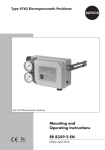
Fig. 1 · Type 6126 Current-to-Pressure Converter with pressure gauge and bracket
Mounting and
Operating Instructions
EB 6126 EN
Edition July 2010
Contents
Contents
Page
1
1.1
1.2
1.3
Description . . . . .
Application . . . . .
Technical data . . .
Principle of operation
2
2.1
Installation . . . . . . . . . . . . . . . . . . . . . . . . . . . . . . . 8
Mounting . . . . . . . . . . . . . . . . . . . . . . . . . . . . . . . . 8
3
3.1
3.2
Connections . . . . . . . . . . . . . . . . . . . . . . . . . . . . . . 9
Electrical connection. . . . . . . . . . . . . . . . . . . . . . . . . . . 9
Pneumatic connection . . . . . . . . . . . . . . . . . . . . . . . . . 10
4
Operation . . . . . . . . . . . . . . . . . . . . . . . . . . . . . . . 10
5
Maintenance . . . . . . . . . . . . . . . . . . . . . . . . . . . . . 12
6
Troubleshooting . . . . . . . . . . . . . . . . . . . . . . . . . . . . 13
7
Dimensions in mm . . . . . . . . . . . . . . . . . . . . . . . . . . . 14
2
EB 6126 EN
.
.
.
.
.
.
.
.
.
.
.
.
.
.
.
.
.
.
.
.
.
.
.
.
.
.
.
.
.
.
.
.
.
.
.
.
.
.
.
.
.
.
.
.
.
.
.
.
.
.
.
.
.
.
.
.
.
.
.
.
.
.
.
.
.
.
.
.
.
.
.
.
.
.
.
.
.
.
.
.
.
.
.
.
.
.
.
.
.
.
.
.
.
.
.
.
.
.
.
.
.
.
.
.
5
5
6
7
Safety instructions
4 The devices may only be mounted, started up or serviced by fully trained
and qualified personnel, observing the accepted industry codes and
practices. Make sure employees or third persons are not exposed to any
danger.
All safety instructions and warnings in these mounting and operating
instructions, particularly those concerning assembly, start-up and
maintenance, must be observed.
4 Any hazards which could be caused in the device by the signal pressure
are to be prevented by means of the appropriate measures.
4 Proper shipping and appropriate storage of the device are assumed.
4 The device with the CE marking fulfills the requirements of the Directive
94/9/EC and the Directive 89/336/EEC.
The declaration of conformity is available on request.
EB 6126 EN
3
Article code
Article code
Explosion protection: Without
Pneumatic connection
¼ - 18 NPT
ISO-228/1 - G ¼
Type 6126- x x x x x x x x x x x x x
0
1
2
i/p module
Type 6109 1)
Type 6112
1
2
Input
4 to 20 mA
0 to 20 mA, without electronics 2)
4 to 20 mA, without electronics 2)
5)
0 to 10 V, 24 V DC auxiliary power
2 to 10 V, 24 V DC auxiliary power
1
2 2
3
4
5
Output
0.2 to 1.0 bar
3 to 15 psi
0.4 to 2.0 bar
6 to 30 psi
Special ranges: 3), 4)
Initial value 0.1 to 0.4 bar; span 0.75 to 1.00 bar
Initial value 0.1 to 0.4 bar; span 1.00 to 1.35 bar
Initial value 0.1 to 0.4 bar; span 1.35 to 1.81 bar
Initial value 0.1 to 0.8 bar; span 1.81 to 2.44 bar
Initial value 0.1 to 0.8 bar; span 2.44 to 3.28 bar
Initial value 0.1 to 0.8 bar; span 3.28 to 4.42 bar
Initial value 0.1 to 1.2 bar; span 4.42 to 5.94 bar
Operating direction
Increasing/increasing
Increasing/decreasing
Degree of protection
IP 54
IP 65
Output pressure gauge
Without
With
Temperature range: Tmin ³ –25 °C
Special version: Without
4
EB 6126 EN
0
2
2
0
0
0
0
1
2
4
5
2
2
2
2
2
2
2
1
1
1
1
1
1
1
1
2
3
4
5
6
7
0
1
0
1
0
1
0
0 0 0
Description
1)
2)
3)
4)
5)
Only with output 0.2 to 1 bar (3 to 15 psi)
Without switch-off electronic function and without zero point and span correction,
not possible with Type 6109 i/p module, output 0.2 to 1 bar (3 to 15 psi)
Raised zero up to 3 bar (45 psi) possible as special version
Specify setting range, e.g. set to 0.1 to 4 bar
output pressure max. 5 bar, supply air 5.4 bar
Input 0 to 5 V possible as special version
Accessories
Mounting accessories for
Order no.
– Mounting bracket for wall mounting
1400-7432
stainless steel (1.4301) (included in the scope of delivery)
– Wall and pipe mounting (2” pipes)
1400-6216
– Attachment to cast yokes acc. to NAMUR
1400-6217
– Attachment to valves with rod-type yokes
1400-6218
according to NAMUR
Pressure gauges for retrofitting
– Pressure gauge: 0 to 1.2 bar range
– Pressure gauge: 0 to 6 bar range
– Pressure gauge: 0 to 10 bar range
– For all pressure gauges: Screw fitting
– Male connector G ¼ onto 4x1 mm hose, brass
– Male connector ¼ NPT onto 4x1 mm hose, brass
– T-piece screw fitting for 4x1 mm hose, brass
1
0080-0185
0080-0186
8520-0032
0250-1090
8582-1452
8582-1523
8582-1480
Description
1.1 Application
The devices are used to convert a direct current input signal into a pneumatic signal for
measuring and control. They are especially
suitable as intermediate elements between
electrical measuring devices and pneumatic
controllers or between electrical control devices and pneumatic control valves.
The input is a load-dependent direct current
from 4 or 0 to 20 mA or a DC voltage signal from 2 or 0 to 10 V with an auxiliary
power of 24 V DC. The output is, for example, a pneumatic signal of 0.2 to 1 bar (3 to
15 psi) or 0.4 to 2 bar (6 to 30 psi) or special ranges up to 5 bar (75 psi).
EB 6126 EN
5
Description
1.2 Technical data
Type 6126-0
Input
0(4) to 20 mA or 0(2) to 10 V (input resistance 30 kW)
Load £ 6 V (corresponds to 300 W at 20 mA,
versions without electronics 200 W at 20 mA £ 4 V)
Output
0.2 to 1 bar (3 to 15 psi) with Types 6109 and 6112 i/p modules
0.4 to 2 bar (6 to 30 psi) with Type 6112 i/p module
Special ranges up to 5 bar (75 psi) with Type 6112 i/p module
Air output capacity 1)
3
2.0 m /h at 0.6 bar output (0.2 to 1 bar)
3
2.5 m /h at 1.2 bar output (0.4 to 2 bar)
Auxiliary power
Supply air
Instrument air at least 0.4 bar above the upper signal pressure range
value, maximum 5.4 bar without upstream pressure regulator
Air consumption 2)
0.08 mn /h at 1.4 bar; 0.1 mn /h at 2.4 bar
24 V DC
(with voltage-to-pressure
converter)
10 to 28 V DC
Performance
3
3
9 to 25 mA (max. 30 mA) for 0(2) to 10 V input
Characteristic: Output linear to the input
Hysteresis
£ 0.3 % of final value, more accurate specifications on request
Deviation from
terminal-based conformity
£ 1 % of final value, more accurate specifications on request
Supply air: 0.1 %/0.1 bar
Influence in % of final
value
Alternating load, supply air failure, interruption of input current < 0.3 %
Ambient temperature:
Lower measuring range value < 0.03 %/K, span < 0.03 %/K
Dynamic response
(IEC 770)
Limiting frequency: 5.3 Hz
Effect of variable mounting
position
Max. 3.5 %; ±1 % when mounted horizontally with Type 6109
Max. 1 %; ±1 % when mounted horizontally with Type 6112
Ambient temperature
–25 to 70 °C
Degree of protection
IP 54/IP 65
Materials
Enclosure: Die-cast aluminum, chromated, plastic coated, glass fiber
reinforced polyamide, other parts made of corrosive-resistant material
Weight
Approx. 0.6 kg
1)
2)
Phase shift: –130°
Measured with 2 m hose 4 x 1 mm
Measured at average output pressure
6
EB 6126 EN
Description
1.3 Principle of operation
The converter consists of an i/p converter
module and a connected volume booster.
The supplied direct current i flows through
the plunger coil (2) located in the field of a
permanent magnet (3). At the balance beam
(1), the force of the plunger coil, which is
proportional to the current, is balanced
against the force of the dynamic back-pressure. The back-pressure is produced on the
flapper plate (6) by the air jet leaving the
nozzle (7). The air supply (SUPPLY 8) flows
into the lower diaphragm chamber, during
which a certain amount of air determined by
the diaphragm position flows past the sleeve
(9) to the output (OUTPUT 36). When the input current increases and, as a result, the
Balance beam
Plunger coil
Permanent magnet
Zero and span adjusters (not in
version without electronics)
5
Switch-off electronic function:
Slide switch (only in 4 to 20 mA
version with electronics)
6
Flapper plate
7
Nozzle
8
Volume booster
8.2 Fixed restrictor
9
Sleeve
10
Diaphragm
forces at the plunger coil increase as well,
the flapper plate (6) moves closer to the nozzle (7). This causes the dynamic back-pressure and the cascade pressure pK forming in
front of the restrictor (8.2) to increase. The
cascade pressure increases until it is equal
to the input current. When the cascade pressure increases, the diaphragm (10) and the
sleeve (9) are pushed downwards, causing
the supply air to increase the output pressure pA until a new state of equilibrium is
reached in the diaphragm chambers. When
the cascade pressure drops, the diaphragm
moves upwards, releasing the sleeve and allowing the output pressure pA to pass
through the sleeve to be vented (EXHAUST
port) until the forces at the diaphragm are
equal again.
1
2
3
4
Type 6109/
Type 6112
i/p Module
Fig. 2 · Functional diagram
EB 6126 EN
7
Installation
Switch-off electronic function
Devices with an input range of 4 to 20 mA
have a slide switch which activates the
switch-off electronic function. This function
causes the input signal to be set to 0 mA
when the switch point falls below a 4.08 ±
tolerance. This function causes the pneumatic output to be vented up to approx.
100 mbar, ensuring, for example, the tight
shut-off of a control valve. The function requires a characteristic which passes through
zero as is the case, for example, for an output signal from 0.2 to 1 bar.
If the characteristic line does not pass
through zero like, for example, for an allocated output signal from 0.8 to 2.7 bar,
then the pneumatic output is vented to a
remaining pressure of approx. 0.3 bar
when the switch-off electronic function is activated.
1.0
bar
0.8
With an output of 0.2 to
1 bar
Approx. 0.1 bar remaining
pressure
0.6
0.4
0.2
4
5
8 12 16 20
mA
bar
With an output of 0.8 to
2.7 bar
Approx. 0.3 bar remaining
pressure
4
3
2
1
4
8 12 16 20
mA
Fig. 3 · Switch-off electronic function and remaining
pressure
8
EB 6126 EN
2
Installation
2.1 Mounting
The converter can be mounted to a wall, a
pipe or directly to a control valve as illustrated on page 14.
The device is delivered with a stainless steel
bracket for wall mounting.
The following mounting accessories are
required depending on the type of mounting
to be used:
4 Pipe mounting, order no. 1400-6216
4 Attachment to valve with cast yoke,
order no. 1400-6217
4 Attachment to valve with rod-type yoke,
order no. 1400-6218
Mounting position
Mount the device horizontally with the pressure gauge (or stopper plug) pointing upwards. If a different mounting position is
used, the zero point must be readjusted for
the 4 to 20 mA version with the switch-off
electronic function.
For converters with a degree of protection
IP 54, it is essential to direct the EXHAUST
port downwards to face the floor.
Connections
A male angle connector conforming to
DIN EN 175301-803 A is used for electrical
connection.
Connections
3.1 Electrical connection
1. Unscrew the fixing screw (1) of the connector plug and pull the plug insert (3)
out of the plug base at the enclosure.
As far as the electrical installation of
the device is concerned, the relevant
national regulations governing the
installation of electrical equipment
and the national accident
prevention regulations of the
country of destination must be
adhered to.
In Germany, these are the VDE
regulations and accident prevention
regulations of the employer's
liability insurance.
5
2. Pull the screw out of the plug and remove
the seal (5).
3. Place a screwdriver at the recess (4) and
lever the plug insert (3) out of the plug
housing.
4. Run the wires for the input signal over
the cable gland of the plug housing to
the terminals of the insert marked 1 (+),
2 (–) and screw them down.
3
4
2
1
2
4
3
1
3
1
Fixing screw
Connector plug housing
Plug insert
Recess
Seal
Cable gland
3
1
2
3
4
5
6
1 (+)
3 (+)
2 (–)
6
24 V DC
only for 0 (2)...10 V
4 (0)...20 mA
0 (2)...10 V
Fig. 4 · Terminal assignment on the plug connector
EB 6126 EN
9
Operation
• For voltage-to-pressure converters
additionally run the wire for the auxiliary power 24 V DC (+) to terminal 3.
• Current-to-pressure converters do not
require a supply voltage.
5. Push the insert into the plug housing,
making sure that the cable gland points
in the correct direction after the connector plug has been reassembled (the plug
housing can be mounted in all four directions, turned at 90° angles around the
insert).
6. Plug the connector plug on the device
and screw tight the screw (1).
3.2 Pneumatic connection
The connections for supply air (SUPPLY 8)
and output air (OUTPUT 36) are designed
as bores with G ¼ or ¼-18 NPT thread (see
page 14).
Note:
Customary male connectors for metal pipes
or plastic hoses can be used. When extending the exhaust by connecting a pipe either
to the exhaust angle piece or directly to the
G or NPT connection, make sure that no water can enter at the end of the pipe. The pipe
must have a sufficiently large cross-section
area of at least 28 mm² = 6 mm inside diameter.
10
EB 6126 EN
4
Operation
The device converts the input signal proportionally into the output signal.
The signal ranges are specified on the
nameplate.
In case of a mounting position that is not
horizontal or when the pressure
gauge/stopper plug does not face upwards,
zero and span can be corrected by approx.
10 % using the electronics. To do this, proceed as follows:
Example:
The output signal 0.2 to 1 bar is to be assigned an input signal of 4 to 20 mA.
1. Unscrew the enclosure cover to access
the ZERO and SPAN potentiometers on
the printed circuit board.
Zero:
2. Connect a pressure gauge (minimum accuracy class 1) to the output of the device.
3. Set the supply air to at least 0.4 bar
above the upper range value of the output signal and apply it to the device.
4. Deactivate the switch-off electronic function at the switch (5) for 4 to 20 mA version.
5. Set the input signal to the lower range
value 4 mA using a suitable current
source. The output signal at the test pressure gauge should indicate a lower
range value of 0.2 bar.
Operation
Should another value be indicated, readjust the zero point accordingly with the
ZERO potentiometer.
Span:
6. Set the input signal to 20 mA using a
suitable current source. The output signal
at the test pressure gauge should indicate the upper range value of 1.0 bar.
Should another value be indicated, readjust the span accordingly with the SPAN
potentiometer.
7. Change the input signal abruptly from
the upper range value 20 mA to 0 mA
(or gently tap the device) and check
whether the output signal assumes the
upper range value, e.g. 1.0 bar. Since
the adjustments of zero point and span
influence each other, check both values
again and correct them, if necessary.
Current-to-pressure
converters
4 to 20 mA version
Slide switch for
switch-off electronic
function
Voltage-to-pressure
converters
0 (2) to 10 V version
8. For 4 to 20 mA versions, reactivate the
switch-off electronic function, if required,
at the switch (5).
Note for voltage input signal:
For voltage-to-pressure converters, proceed
in the same way as already described. The
pneumatic output signal from, for example,
0.2 to 1 bar is assigned to the signal range
0 or 2 to 10 V with the ZERO and SPAN
adjusters (see nameplate).
Converters with voltage input do not have
the switch-off electronic function.
Fig. 5 · Adjusters with enclosure
EB 6126 EN
11
Maintenance
5
Maintenance
No particular maintenance steps are prescribed.
Proper functioning of the converter can only
be guaranteed when the instrument air applied to the device is always clean. The air
filter and separator of the pressure reducing
station should be checked at regular intervals.
The pneumatic connections have filters with
plastic rims (order no. 0550-0213) which
can be unscrewed and changed or cleaned.
12
EB 6126 EN
Troubleshooting
6
Troubleshooting
Problem
Possible cause
Countermeasure
Comments
No output signal
despite changing the
input signal
Supply air not
connected
Check supply air connection, see section 3.2
Incorrect terminal
assignment
Connect + and –
terminals correctly, see
section 3.1
CAUTION!
Current-to-pressure converter does not need any
extra voltage!
Do not connect 24 V DC!
Voltage-to-pressure
converter requires a
24 V DC voltage supply!
(see section 3.1)
Incorrect input signal
Connect correct signal
See nameplate:
0 – 20 mA or 4 – 20 mA
0 – 10 V or 2 – 10 V
Converter constantly
vents off air loudly
Connections for supply Check pneumatic
connection, see
air and output at the
section 3.2
converter mixed up
Converter does not
reach 100 % output
Supply air is too low
e.g. 20 mA input:
Output only 70 %
instead of 100 %
Input signal faulty
Supply air must be
0.4 bar greater than
the max. output signal
(supply air = 0.4 bar)
See nameplate:
Output 0.2 – 1 bar
Check whether the input
signal at the terminals
reaches 100 %
(100 % is in standard
version, e.g. 20 mA,
with split-range 12 mA)
CAUTION!
Current-to-pressure converter has a load of max.
6 V.
Check specification
concerning control.
–> Supply air at least
1.4 bar; max. 6 bar
EB 6126 EN
13
Dimensions in mm
7
Dimensions in mm
136
120
100
Wall mounting
with mounting
bracket
(1400-7432)
Mounting bracket
Ø7
50
74.5
126
OUTPUT
Electrical connection
75.5
Mounting on a control valve with accessories
(1400-6217)
Wall and pipe mounting
(1400-6216)
EXHAUST
40
188.5
113
74.5
127
40
95
Pressure gauge
(accessories)
EXHAUST
IP 65
SUPPLY
158.5
2"
178.5
77
14
Pipe mounting
8
74.5
Attachment to valve with
cast yoke
EB 6126 EN
Attachment to valve with
rod-type yoke
(1400-6218)
74.5
EB 6126 EN
15
EB 6126 EN
S/Z 2011-11
SAMSON AG · MESS- UND REGELTECHNIK
Weismüllerstraße 3 · 60314 Frankfurt am Main · Germany
Phone: +49 69 4009-0 · Fax: +49 69 4009-1507
Internet: http://www.samson.de