1
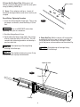
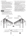
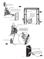
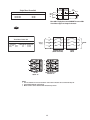
17. Electrical: Have a certified electrician run
appropriate power supply to motor, Fig. 20 & 21.
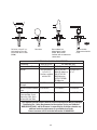
Size wire for 20 amp circuit. See Motor Operating
Data Table.
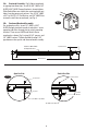
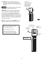
Service From
Master Control Panel
(3 Wire) Into Junction
Box On Power Unit
Attach With Strain
Relief Provided
CAUTION Never operate the motor on line voltage
less than 208V. Motor damage may occur.
IMPORTANT: Use separate circuit for each power
unit. Protect each circuit with time delay fuse or
circuit breaker. For single phase 208-230V, use 20
amp fuse. Three phase 208-240V, use 20 amp fuse.
For three phase 400V and above, use 10 amp fuse. For
three phase 380V use 16 amp fuse. For wiring see Fig.
20 & Fig. 21. All wiring must comply with NEC and all
local electrical codes.
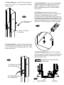
Fig. 25a
Note: 60Hz. single phase motor CAN NOT be run on
50Hz. line without a physical change in the motor.
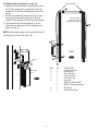
NOTE: Assure cord used for connection
between the overhead switch and power
unit is of the type specified in:
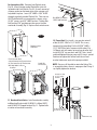
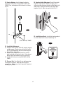
Attach black wire
to one motor wire.
From Master
Control Panel.
UL201, Sections 10.1.1.3 & 10.1.1.4
(Example: SO, G, STO) Size for 25 amp
circuit. See UL 201, Section 15 for proper
wiring requirements for this connection.
Attach white
wire to
one motor wire.
Attach ground
wire here.
Attach ground wire to
screws provided.
14