1
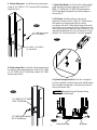
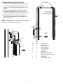
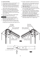
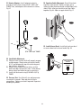
5. Column Extensions: Install the column extensions
using (2) 1/2”-13NC x 1 1/4” Carriage HHCS and Nylon
Locknuts, Fig. 4.
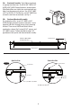
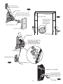
7. Latch Cable Guides: Install the latch cable conduit
guide brackets to column extensions with (1) 1/4”20NC x 1” HHCS and 1/4”-20NC Flanged Locknuts,
HHCS should go through hole nearest the edge as
shown, Fig. 6.
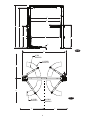
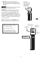
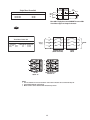
8. Lift Setting: Position columns in bay using
dimensions shown in Fig. 1a & Fig. 1b. Place column
with power unit mounting bracket on vehicle
passenger side of lift. Both column base plate backs
must be square on center line of lift. Notches are cut
into each base plate to indicate center line of lift. Use
appropriate equipment to raise carriage to first latch
position. Be sure locking latch is securely engaged.
Fig. 4
1/2”-13NC Nylon Locknut
& 1/2” Flat Washer
Fig. 6
1/2”-13NC x 1-1/4” HHCS &
1/2” Flat Washer
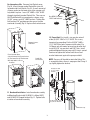
6. Reinforcement Bar: Install the reinforcement bar to
the column and column extension using (2) 1/2”-13NC
x 1-1/4” HHCS, (4) 1/2” Flat Washer, and (2) 1/2”-13NC
Nylon Locknut Fig. 5.
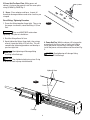
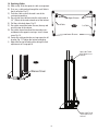
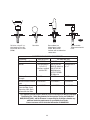
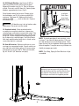
9. Cylinder Fitting/Flow Valve: Push the carriage to
first lock and then install the flow valve and 90° elbow
to the cylinder through the small opening on the bottom of the column. Fig 7.
Fig. 5
CAUTION Overtightening will damage fitting
resulting in fluid leakage.
1/2”-13NC x 1-1/4” HHCS
& 1/2” Flat Washer
1/2”-13NC Nylon Locknut
& 1/2” Flat Washer
Fig. 7
5
Flow Valve Body
90° Elbow