1
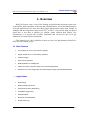
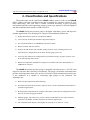
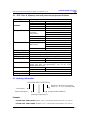
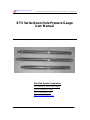
RubyTek System Corp.
704 –3607B, 49 Street, NW, Calgary, Alberta, Canada T3A 2H3 Tel: 1-403 890 5196
RTS Series Down-Hole Pressure Gauge
User Manual
RubyTek System Corporation,
704 –3607B, 49 Street, NW, Calgary
Alberta, Canada T3A 2H3
Tel: +1- (403)890 5196
http://www.rubyteksys.com
Copyright 2005-2007 RubyTek System Corporation -
Last Update: Jue 18, 2007
RTS Series Down-Hole Pressure Gauge User Manual v1.10
RubyTek System Corp
Table of Contents
1.
2.
3.
4.
Overview .................................................................................................................... 2
1.1
Main Features..................................................................................................... 2
1.2
Applications ........................................................................................................ 2
Classification and Specifications ............................................................................. 3
2.1
RTS Class A (Memory read out) pressure gauge specifications ........................ 4
2.2
Ordering information.......................................................................................... 4
2.3
RTS class B (Surface read out) pressure gauge specifications .......................... 5
2.4
Ordering information.......................................................................................... 5
Installation and Operating Instructions ................................................................. 6
3.1
Assembly and configure the gauge ..................................................................... 6
3.2
After removal of the gauge................................................................................ 10
3.3
Upload the samples........................................................................................... 11
3.4
Plot and analyze the data.................................................................................. 12
3.5
Servicing of the gauge....................................................................................... 14
Troubleshooting ...................................................................................................... 15
Copyright 2007 RubyTek System Corporation -
1
Revision Date: June 18, 2007
RTS Series Down-Hole Pressure Gauge User Manual v1.10
RubyTek System Corp
1. Overview
RubyTek System Corp. is one of the leading and professional developers that focus
on down-hole data acquisition, collection and communications, record and monitoring for
oil & gas applications. We offer down-hole gauges that pressure ranges from 3000psi to
20000psi and the temperature ranges from 125℃ to 200℃, with extreme high job upload
speed that is less than 4 minutes per million counts (million data points). Our
commitment is to provide the excellent instrument and services for the oil & gas
industrials in extreme harsh environment.
This manual gives a brief guideline on how to select, use and maintain a RubyTek’s
RTS series down-hole gauge.
1.1 Main Features
•
Long battery life and Large memory capacity
•
Single cell AA size or C size battery operation
•
Pressure trigger
•
Sour service operation
•
Data separation for multiple jobs
•
Cable connection & Surface readout for real-time applications
•
Software for on-site configuration and data analysis support with Win2000/XP/Vista
1
.2Applications
•
Well Testing
•
Monitor Well Performance
•
Permanent Sensors (Monitoring)
•
Completion Diagnostics
•
Well Stimulation
•
Reservoir Characterization
•
Gradient Surveys
Copyright 2007 RubyTek System Corporation -
2
Revision Date: June 18, 2007
RTS Series Down-Hole Pressure Gauge User Manual v1.10
RubyTek System Corp
2. Classification and Specifications
The product lines can be classified as class A (MRO, memory read out) and class B
(SRO, surface read out) according to the data recording type (memory storing or realtime transferring), and each class is further classified according to their operating
environment (pressure and temperature ranges), sensor type (Quartz or Silicon-Sapphire)
and data communication interface (USB or RS232).
The class A down-hole pressure gauge is designed with battery power and target for
portable applications. The advantages to compare with traditional products are:
1) Higher data transfer speed for job upload (12Mbps);
2) User GUI tool for data plot and data comparison/analysis
3) No extra download box or USB/RS232 converter needed;
4) Battery monitor and life evaluate;
5) System clock & flexible job schedule settings (system clock, sampling interval, job
start/end time), configuration can be done after the gauge power on;
6) Auto-Log-File function for configuration or operation tracking, no paper works to write
down start and stop date on-site;
7) Backward compatible with RS232 COM port is available with extra download box or
USB/RS232 converter.
The class B down-hole pressure gauge is designed with cable power (+12V DC) and
target for real time data collecting or monitoring. The gauge can monitor and transmit the
pressure and temperature data up to surface in real time. Both communication and power
is one conductor. It is capable of connecting eight gauges in one conductor. The
advantages are:
1) Real-time data acquisition and monitoring;
2) No battery life limit and no memory capacity limit, one-time installation and suitable for
permanent applications;
3) Bi-directional communications in single cable enable control and re-configuration can be
done on-site after the gauge installed;
4) Multiple gauges (up to 8 devices) can be connected and shared in one cable conductor
with a bit-rate 800bps, flexible connection for network applications;
5) The communication distance (well depth) can reach up to 4.5 miles or 7.2 km.
Copyright 2007 RubyTek System Corporation -
3
Revision Date: June 18, 2007
RubyTek System Corp
RTS Series Down-Hole Pressure Gauge User Manual v1.10
2.1 RTS Class A (Memory read out) pressure gauge specifications
Sensor Type
Silicon-Sapphire
Range:
Accuracy
Resolution
Over capacity
Drift
Atmosphere
(Operating
Temperature)
Up to 20000 PSI
0.03%(FS)
0.0003%
110%(FS)
3psi/year
150℃ (Max)
175℃ (Max)
185℃ - 200℃ (Max)
Accuracy
0.5℃
Resolution
0.01℃
Over capacity
105%(FS)
Sample numbers
0.5 million
(Data Points)
1 million
2 million
Data format
Time/Pressure/Temp/Date
1 second to 6 hours (configurable, set on surface)
MRO (Memory read out)
Single AA or C lithium battery pack
Battery voltage monitoring feature
Interface
USB, RS232
Bit rate (upload job)
12Mbps, 230Kbps
Friendly user GUI software for gauge configuration, job
upload and data view/plot/analysis, run on PC with
Window2000/XP/Vista.
Outside diameter
0.75”, 1”, 1.25”
Length
10 – 12”
H2S
Inconel718-NACE, SS17-4 PH
Pressure
Temperature
Data
Sample rate
Working mode
Power
Battery
Communications
User Interface
Size
Environment
Housing material
2.2 Ordering information
RTS-XXX-XXX-XXX-XXXA
Interface(U/R), Sensor Type(S/Q),
Size(0.75”/ 1”/ 1.25”) & Class(A/B)
Part Number
Max Pressure(Kpsi )
Sample Numbers(Million)
Operating Temperature(℃)
Example:
RTS-06K-150C-0.5M-RS075A (6000psi, 150℃, 0.5M samples/ RS232/ Silicon/0.75”/ class A)
RTS-20K-175C-1.0M-UQ100A (20000psi, 175℃, 1.0M samples/ USB/ Quartz/1.00”/ class A)
Copyright 2007 RubyTek System Corporation -
4
Revision Date: June 18, 2007
RubyTek System Corp
RTS Series Down-Hole Pressure Gauge User Manual v1.10
2.3 RTS class B (Surface read out) pressure gauge specifications
Sensor Type
Silicon-Sapphire or Quartz
Range:
Accuracy
Resolution
Over capacity
Drift
Atmosphere
Pressure
Temperature
Data format
Sample rate
Working mode
Power
Communications
User Interface
Size
Environment
Housing material
Up to 20000 PSI
0.03%(FS)
0.0003%
110%(FS)
3psi/year
150℃ (Max)
175℃ (Max)
185℃ - 200℃ (Max)
Accuracy
0.5℃
Resolution
0.01℃
Over capacity
105%(FS)
Time/pressure/temperature/Date
3 seconds to 6 hours (configurable, set on surface)
SRO (surface read out)
12V DC
Interface
Both USB and RS232
Bit rate (real-time)
1.0 -- 10 kbps
Friendly user GUI software for gauge configuration, job
upload and data view/plot/analysis, run on PC with
Window2000/XP/Vista.
Outside diameter
1”, 1.25”
Length
6”
H2S
Inconel718-NACE, SS17-4 PH
2.4 Ordering information
RTS-XXX-XXX-XXX-XXXB
Interface(U/R), Sensor Type(S/Q),
Size(0.75”/ 1”/ 1.25”) & Class(A/B)
Part Number
Bit Rate for communications(kbps)
Max Pressure(Kpsi)
Operating Temperature(℃)
Example:
RTS-10K-175C-1.5K-RS100B (10000psi, 175℃, 1.5Kbps/ RS232/ Silicon/1.0”/ class B)
RTS-20K-185C-10K-UQ125B (20000psi, 185℃, 10Kbps/ USB/ Quartz/1.25”/ class B)
Copyright 2007 RubyTek System Corporation -
5
Revision Date: June 18, 2007
RubyTek System Corp
RTS Series Down-Hole Pressure Gauge User Manual v1.10
3. Installation and Operating Instructions
3.1 Assembly and configure the gauge
1. Install the O-rings
Make sure the O-rings and threads on the gauge are properly lubricated before
installation.
Threads
O-rings
Figure 1: The O-ring installation
2. Connect the lithium battery
Line up the red dot on the lithium battery with the red dot on the gauge and insert
carefully. If this does not happen gently, double check to make sure the red dots are
line up. The gauge starts to work immediately after the battery pack is connected. The
gauge will goes to log data and put data into the flash memory after 10 minutes if the
user does not /or forget to configure the gauge.
Battery Pack
O-rings
Electronics Housing
Figure 2: Connect the battery pack
3. Connect the download adapter
Line up the red dot on the download adapter with the red dot on the lithium
battery and insert carefully. If this does not happen gently, double check to make sure
the red dots are line up. Connect the download adapter and the PC computer with a
USB cable (type B connector on the download adapter side and type A connector on
the PC side).
Copyright 2007 RubyTek System Corporation -
6
Revision Date: June 18, 2007
RTS Series Down-Hole Pressure Gauge User Manual v1.10
RubyTek System Corp
Download Adaptor
Figure 3: The download adaptor
4. Configure the gauge
1) Start the RubyTek user software and switch to the battery page if the user software
finds the gauge. Otherwise, It will exit if the software can’t find a gauge. Below is the
battery page.
Figure 4: The battery page
Copyright 2007 RubyTek System Corporation -
7
Revision Date: June 18, 2007
RTS Series Down-Hole Pressure Gauge User Manual v1.10
RubyTek System Corp
Battery pack information such as the serial number can be filled into Battery
Specification box and download into the gauge. The battery voltage can be measured by
click the Current Voltage button.
Any standard 150℃—185℃ single AA lithium pack should have a voltage from 3.63.9V (refer to manufacturer data sheet) when new. The gauge will start to record samples
with voltages less than Alarm threshold. A lithium battery with a starting voltage under
manufacture specification should not be used. If a new battery shows a voltage less than
expected, it may have a passivity layer problem. It is unknown what type of
environmental changes the gauge experienced while it is down the well. Extreme
temperature changes will definitely shorten the lifespan of the battery. Therefore it is
suggested that a new battery be used each time the gauge is run into the well.
2) Configure the job schedule.
User can set sample interval and job hours for this interval, the maximum number
for interval settings reaches up to 32. The software can estimate how many hours/days of
this schedule. This schedule will store into flash after you click the download button (see
Figure 5).
Figure 5: The job schedule page
3) Set system time.
Copyright 2007 RubyTek System Corporation -
8
Revision Date: June 18, 2007
RTS Series Down-Hole Pressure Gauge User Manual v1.10
RubyTek System Corp
The computer’s system time will download into the gauge in the job schedule page
after you click the View Time button and then the Set Time button. You can check the
gauge time by clicking Get Time button.
4) Set log start time
There are two ways to set the gauge log start time. One is set the delay time relate to
the gauge time. The default value is 10 minutes after the gauge powers on. Another is to
set exact time (year/month/date, hour/minute/second), the gauge will record the samples
after the time out.
5) Fill some user comment
Go to the gauge information page, some information can be filled into user comment
box and this information can be downloaded into the gauge after the Write Comments
button clicked.
Figure 6: The gauge information page
5. Remove the download adapter.
One hand holds the battery and another hand pull out the download adapter carefully
from the battery pack. Push the battery pack toward the electronics housing slightly to
guarantee fasten connection between the gauge and the battery pack.
Copyright 2007 RubyTek System Corporation -
9
Revision Date: June 18, 2007
RTS Series Down-Hole Pressure Gauge User Manual v1.10
RubyTek System Corp
6. Install the battery housing
Slide the battery housing over the battery and tighten it onto the electronics housing.
If this process is not easily done, stop. Remove the housing and the battery. Try sliding
the battery into the housing by hand to see if there is any obstruction. If there is a
problem, check to see if the inside of the housing is clear and check the outside of the
battery for foreign material or swelling. The battery will twist off inside of the electronic
housing socket if it does not fit freely in the battery housing.
Battery housing
Gauge Body
Lithium Battery
Bullnose
O-rings
Figure 7: The battery housing installation
Tighten the battery housing on to the electronic housing using 5/8” or 17mm
wrenches on the wrench flats. These gauges are O-ring sealed (not metal to metal sealed)
and therefore should only be slightly more than hand-tight.
* Do not over-tighten and do not use pipe wrenches on these gauges as you
could damage the housing.
7. The gauge is now ready to be run into a well.
3.2 After removal of the gauge
1. The gauge should be allowed the cool sufficiently before working with it.
2. Loosen the battery housing from the electronics housing using a 5/8” or 17mm
wrench.
3. Slowly remove the battery housing from the electronics housing. Ensure no pressure
has built up inside housing. Lift the battery housing off of the battery.
4. Remove the battery pack from the electronics housing socket by gripping the battery
as close to the pin as possible and pull straight off the electronics housing. *Do not
twist the battery!! It is now time to start downloading the information recorded by
the gauge.
Copyright 2007 RubyTek System Corporation -
10
Revision Date: June 18, 2007
RTS Series Down-Hole Pressure Gauge User Manual v1.10
RubyTek System Corp
3.3 Upload the samples
1. Line up the red dot on the download adapter with the red dot on the gauge and insert
carefully. They will only connect this way. Do not force or twist!! If the connection
is difficult, stop and look to see what the obstruction might be. Clear all obstructions
and try the connection again. Connect another side of the cable of download adapter
to a PC computer’s USB port.
Figure 8: Cable connection for data upload
2. Start the RubyTek user software and switch to the run data page and upload the jobs
recorded in the gauge. If the log start time didn’t set before, it could be updated here
during job upload. Please read the help manual of the RubyTek logger software for
more detail.
Figure 9: The run data page
Copyright 2007 RubyTek System Corporation -
11
Revision Date: June 18, 2007
RTS Series Down-Hole Pressure Gauge User Manual v1.10
RubyTek System Corp
3.4 Plot and analyze the data
1. Plot and compare the job data
After uploaded, the job can be opened and plotted in the plot data page for further
analysis. Two jobs can be opened and plotted (with the Draw1, Draw2 button) at the
same time for comparison. Statistic information (maximum pressure and temperature,
mean pressure value, etc.) inside the current viewing window and the values at current
cursor can also be displayed for reference (see Figure 10). Please read the help manual of
the RubyTek logger software for the detail.
Figure 10: The plot data page
2. Analyze the job details by “Zoom In/Out” and “Message Tip”
After opened, in order to analyze the details of the data, the plot can be zoom in with
“+++” or zoom out with the “---” button, and can be scrolled by tracking the scrollbar, or
forward with “>>>” and backward with “<<<” button. The zoom feature can also be
finished with mouse by a “left button down & drag to select area” action, i.e., drag
from top-left to bottom-right is the zoom in, and drag from bottom-right to top-left is the
zoom out (see Figure 11).
By moving the mouse cursor closely to a data point on the plot, the user can easily to
view its detail values as a “message tip” on the selected point (see Figure 12).
Copyright 2007 RubyTek System Corporation -
12
Revision Date: June 18, 2007
RTS Series Down-Hole Pressure Gauge User Manual v1.10
RubyTek System Corp
Figure 11: Select an area to zoom in for more detail
Figure 12: Zoom in/out and message tip for data analysis
Copyright 2007 RubyTek System Corporation -
13
Revision Date: June 18, 2007
RTS Series Down-Hole Pressure Gauge User Manual v1.10
RubyTek System Corp
3.5 Servicing of the gauge
1. After all data is uploaded from the gauge, carefully disconnect all components.
2. Clean and lubricate the gauge after use. Replace all O-rings after every run to protect
the gauge from potential damage caused by failure. There are only two O-rings on the
gauge at the top section of the electronics housing. Standard O-rings are number 014V90 that supplied with the tools. O-rings should be selected based on the environment
the tool will be run in.
O-rings
Gauge Body
Pressure Transducer
Gauge Threads
Pressure port
Bullnose /Crossover
Gauge Threads
3. Cleaning the transducer
Copyright 2007 RubyTek System Corporation -
14
Revision Date: June 18, 2007
RTS Series Down-Hole Pressure Gauge User Manual v1.10
RubyTek System Corp
Remove the bullnose or crossover after every run and clean the pressure ports. If the
pressure ports get plugged, then the gauge may not read accurately. With the bullnose or
crossover adapter off, carefully rinse the pressure transducer without directly touching it.
CAUTION: DO NOT TOUCH THE PRESSURE TRANSDUCER DIRECTLY
AS IT CAN BE DEMAGED VERY EASILY. WHEN THE TOOL IS NOT BEING
SERVICED, ENSURE THE BULLNOSE IS INSTALLED ON THE GAUGE TO
PROTECT THE TRANSDUCER.
4. Lubricating the Gauge Threads
The threads on the top of the electronics housing and on the bullnose should be
lubricated with the proper lubricant, such as Dow Corning 55-O-ring lubricant. This
should be done prior to usage.
a) It should be noted that the gauge does contain electronics and should be treated
gently whenever possible. Store gauges in their storage cases when not in use.
b) Never submerse the tool in fluid unless it is completely assembled.
c) If you are running a slick line test, do no exceed 150 feet per minute when
running the gauges into and out of the hole.
4. Troubleshooting
Copyright 2007 RubyTek System Corporation -
15
Revision Date: June 18, 2007