1
Using the 1756-HYD02 Module Features
4-13
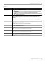
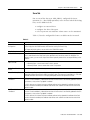
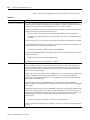
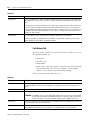
Table 4.6
Feature:
Definition:
Absolute Feedback
Offset
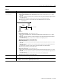
The absolute offset is used to place the machine zero point at the desired location relative to the zero point of the
LDT. The LDT zero point is inside the transducer head and physically unattainable.
Calculated
Values:Conversion
Constant
Calculation derived from values based on the configuration values entered for the LDT.
The calculated conversion "K" constant is derived based on the LDT configuration values entered on the Feedback
tab. After proper LDT values are entered and the Calculate button is selected, the resultant "K" value is calculated.
This "K" value must be taken from this tab and entered in as the Conversion constant on the Conversion tab.
You must type the new conversion constant in the Conversion Constant field on the Conversion tab. RSLogix 5000
does not automatically update the field after you use the Calculate button on this tab.
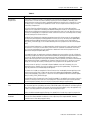
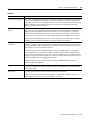
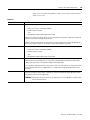
Calculated
Calculation derived from values based on the configuration values entered for the LDT.
Values:Minimum
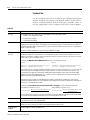
Servo Update Period You can use the calculate button located on the Feedback tab to calculate the appropriate K constant value. The
calculated K constant is derived based on the LDT configuration values entered on the Feedback tab, and must be
taken from that tab and used here.
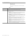
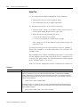
Conversion Tab
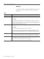
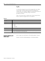
Use this tab to view the Positioning Mode and configure the Feedback
Resolution for an axis. Table 4.7 lists the configurable features
available on the Conversion tab.
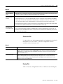
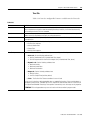
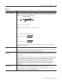
Table 4.7
Feature:
Definition:
Positioning Mode
The Linear positioning mode is the only positioning mode available on the 1756-HYD02 module. This mode
provides a maximum total linear travel of 230,000 feedback counts. With this mode, the unwind feature is
disabled and you can specify the positive and negative travel limits for the axis to limit the linear travel
distance traveled by the axis.
Conversion Constant
Type the number of feedback counts per position unit. This conversion – or “K” – constant allows axis
position to be displayed, and motion to be programmed, in the position units set in the Units tab. The
conversion constant is used to convert axis position units into feedback counts and vice versa. You can
calculate this value on the Feedback tab.
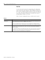
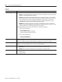
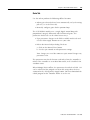
Homing Tab
Table 4.8 lists the configurable features available on the Homing tab.
Publication 1756-UM525A-EN-P - June 2003