1
RingMaster™
Planning Guide
Release
7.4
1 February 2011 (Release Date)
Part Number: 730-9502-0230, Revision C
Copyright © 2011, Juniper Networks, Inc.
Juniper Network, Inc.
1194 N. Mathilda Avenue
Sunnyvale, CA 94089
USA
408-745-2000
www.juniper.net
ii
Copyright © 2011, Juniper Networks, Inc.
About This Guide
RingMaster 7.4 Planning Guide
This guide is part of a Publications Suite intended for network administrators or persons responsible
for installing and managing a Wireless Local Area Network (WLAN) using RingMaster 7.4 software.
This RingMaster 7.4 Planning Guide provides an overview and introduction to tools and procedures
used for preparing a baseline plan for a Wireless Local Area Network (WLAN) using RingMaster 7.4
software.
RingMaster 7.4 software provides network planning, configuration and management tools described
in detail in this and other RingMaster 7.4 publications listed below. Preparing a baseline plan for a
WLAN, as described in this publication, helps you determine equipment and configurations required to
meet your network’s service goals. This planning precedes physical installation of WLAN equipment.
You plan a WLAN to support services you will offer to employees, guests, and/or customers.
As described in detail in the RingMaster 7.4 Quick Start Guide, you install RingMaster Services and
RingMaster Client software on selected hosts. You then start using RingMaster Services on a host
and a RingMaster Client on either the same or a different host to begin network planning for a new or
extended WLAN.
RingMaster 7.4 Publication Suite
Publications that make up the RingMaster Publication Suite are:
❑
RingMaster 7.4 Quick Start Guide — This guide provides a description of prerequisites and
procedures required to install and begin using RingMaster 7.4 software. Information is
provided about system requirements for optimum performance, as well as how to install
RingMaster Client and RingMaster Services software.
❑
RingMaster 7.1 Planning Guide (this document) — This guide is described above.
❑
RingMaster 7.1 Configuration Guide— This guide provides instructions for configuring a WLAN
with the RingMaster tool suite. It describes RingMaster 7.4 WLAN configuration tools. It is
intended for administrators or persons responsible for configuring a WLAN using RingMaster
7.4 software.
❑
RingMaster 7.1 Management Guide — This guide provides instructions for managing a WLAN
with the RingMaster tool suite. It describes RingMaster 7.4 WLAN management and
monitoring tools. It is intended for administrators of WLANs using RingMaster 7.4 software.
Mobility System Configuration and Management
RingMaster 7.4 is used with Juniper Mobility System hardware and software, as described in the
following publications:
❑
Juniper Mobility System Software Configuration Guide — This guide provides instructions for
configuring and managing a system using the Juniper Mobility System Software (MSS)
Command Line Interface (CLI).
❑
Juniper Mobility System Software Command Reference — This publication provides functional
and alphabetic reference to all MSS commands supported on MXs and MPs
❑
Juniper Mobility Exchange Hardware Installation Guide — Instructions and specifications for
installing an MX.
❑
Juniper Mobility System Software Quick Start Guide — Instructions for performing setup of
secure (802.1X) and guest (WebAAA™) access, and configuring a Mobility Domain for roaming
❑
Juniper Mobility Point MP-422 Installation Guide — Instructions and specifications for installing
an MP access point and connecting it to an MX.
❑
Juniper Mobility Point MP-620 Installation Guide — Instructions and specifications for installing
the MP-620 access point and connecting it to an MX.
Copyright © 2011, Juniper Networks, Inc.
i
❑
Juniper Regulatory Information — Important safety instructions and compliance information
that you must read before installing Juniper Networks products
Documentation Conventions
This section describes documentation conventions used by various RingMaster 7.4 publications.
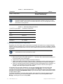
Safety and Advisory Notices
The following types of safety and advisory notices appear in this guide.
This situation or condition can lead to data loss or damage to the product or
other property.
This is a process or procedural tip or other useful suggestion.
Tip
This information you should note relevant to the current topic.
This alerts you to a possible risk of personal injury or major equipment problems.
Hypertext Links
Hypertext links appear in Blue.
As an example, this is a link to Contacting the Technical Assistance Center.
Illustration Formats
Whenever possible, RingMaster screens, windows and dialogs are shown in their entirety, with
consistent relative sizes, except where large sizes precludes this, then they are shown as large as
possible. In addition to overall screen, window and dialog box resizing, you can adjust columns in
tables, etc. to change their appearance. To change these items, move your cursor over a border,
column separator, etc. and you will see a “resize” indication (a double ended arrow).
Text and Syntax Conventions
Juniper guides use the following text and syntax conventions:
ii
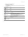
Convention
Use
Monospace text
Sets off command syntax or sample commands and system responses.
Bold text
Highlights commands that you enter or items you select.
Italic text
Designates command variables that you replace with appropriate values
or highlights publication titles or words requiring special emphasis.
Copyright © 2011, Juniper Networks, Inc.
Convention
Use
Bold italic text font
Bold italic text font in narrative, capitalized or not, indicates a program
name, function name, or string.
Menu Name > Command
Indicates a menu item. For example, File > Exit indicates that you select
Exit from the File menu.
[ ] (square brackets)
Enclose optional parameters in command syntax.
{ } (curly brackets)
Enclose mandatory parameters in command syntax.
| (vertical bar)
Separates mutually exclusive options in command syntax.
For information about Trapeze support services, visit
http://www.trapezenetworks.com/supportportal/,
or call 1-866-877-9822 (in the US or Canada) or +1 925-474-2400 and select option 5.
Juniper Networks sells and services its products primarily through its authorized resellers and
distributors. If you purchased your product from an authorized Juniper reseller or distributor and do
not have a service contract with Juniper Networks, you must contact your local reseller or
distributor for technical assistance.
Contacting the Technical Assistance Center
Contact the Juniper Networks Technical Assistance Center (TAC) by telephone, email, or via web
support portal.
❑
Within the US and Canada, call 1-866-TRPZTAC (1-866-877-9822).
❑
Within Europe, call +31 35 64 78 193.
❑
From locations outside the US and Canada, call +1 925-474-2400.
❑
In non-emergencies, send email to [email protected]
❑
If you have a service contract or are a Juniper Authorized Partner, log in to http://
www.trapezenetworks.com/supportportal/ to create a ticket online.
TAC Response Time
TAC responds to service requests as follows:
Contact Method
Telephone
Email
Priority
Response Time
Emergency
One hour
Non-emergency
Next business day
Non-emergency
Next business day
Information Required When Requesting Service
To expedite your service request, please have the following information available when you call or
write to TAC for technical assistance:
❑
Your company name and address
❑
Your name, phone number, cell phone or pager number, and email address
❑
Name, model, and serial number of the product(s) requiring service
❑
Software version(s) and release number(s)
❑
Output of the show tech-support command
❑
Wireless client information
❑
License levels for RingMasterTM and Mobility ExchangeTM (MX™) products
Copyright © 2011, Juniper Networks, Inc.
iii
❑
Description of any problems and status of any troubleshooting effort
Main Menu “Report Problem” Tool
You can click Help from the RingMaster Menu bar to access online help and to send a report to
Trapeze TAC electronically:
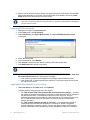
1. Select Help > Help to display HTML help about configuring and using RingMaster.
Select Help > Report Problem to report a problem to Juniper Technical Support. This dialog
allows you to report problems to Juniper Networks by filling in particulars and then clicking
Send Now to compose and send an email to Juniper.
Warranty and Software Licenses
Current Juniper Networks warranty and software licenses are available at
http://www.trapezenetworks.com/support/warranty.
Limited Warranty for Hardware and Software
TERMS AND CONDITIONS OF SALE
1. Software
Any software provided is licensed pursuant to the terms of Trapeze Networks' Software
License Agreement, an electronic copy of which is provided with the Software and a printed
copy of which is available upon request. The terms and conditions of the Software License
iv
Copyright © 2011, Juniper Networks, Inc.
2.
3.
4.
5.
6.
Agreement are incorporated herein in its entirety in this Terms and Conditions of Sale (“Terms
and Conditions of Sale”) by this reference. The terms of the Software License Agreement
control, except for the limited warranty set forth below (“Limited Warranty”).
Limited Hardware Warranty
Trapeze Networks, Inc. (“Trapeze Networks” or “Trapeze”) warrants to Customer, subject to
the limitation and disclaimer below, that all Trapeze hardware will be free from defects in
material and workmanship under normal use as follows: (a) if the hardware was purchased
directly from Trapeze Networks, for a period of one (1) year after original shipment by Trapeze
Networks to Customer or (b) if the hardware was purchased from a Trapeze Networks
Authorized Reseller, for a period of one (1) year from the date of delivery to Customer, but in
no event more than fifteen (15) months after the original shipment date by Trapeze (“Limited
Hardware Warranty”).
The date of original shipment from Trapeze Networks will be determined by shipping evidence
on file at Trapeze Networks. This Limited Hardware Warranty extends only to the Customer
who was the original purchaser of the hardware and may not be transferred to any subsequent
repurchasing entity. During the Limited Hardware Warranty period upon proper notice to
Trapeze Networks by Customer, Trapeze Networks will, at its sole option, either:
❍ Repair and return of the defective hardware;
❍ Replace the defective hardware with a new or refurbished component;
❍ Replace the defective hardware with a different but similar component that
contains compatible features and functions; or
❍ Refund the original purchase price upon presentation of proof of purchase to
Trapeze Networks.
Restrictions on the Limited Hardware Warranty.
This Limited Warranty does not apply if hardware (a) is altered from its original specifications,
(b) is installed, configured, implemented or operated in any way that is contrary to its
documentation, (c) has damage resulting from negligence, accident, or environmental stress,
(d) was subject to unauthorized repair or modification or (e) is provided to Customer for
pre-production, evaluation or charitable purposes.
Limited Software Warranty
Trapeze Networks warrants to Customer, subject to the limitation and disclaimer below, that
the software will substantially conform to its published specifications as follows: (a) if the
software was purchased directly from Trapeze Networks, for a period of ninety (90) days after
original shipment by Trapeze Networks to Customer or (b) if the software was purchased from
a Trapeze Networks Authorized Reseller, for a period of ninety (90) days from the date of
delivery to Customer commencing not more than ninety (90) days after original shipment date
by Trapeze), (“Limited Hardware Warranty”). The date of original shipment from Trapeze
Networks will be determined by shipping evidence on file at Trapeze Networks. This Limited
Software Warranty extends only to the Customer of original purchaser of the software and may
not be transferred to any subsequent repurchasing entity.
During the Limited Software Warranty period upon proper notice to Trapeze Networks by
Customer, Trapeze Networks will, at its option, either:
❍ Use reasonable commercial efforts to attempt to correct or provide workarounds
for errors;
❍ Replace the software with functionally equivalent software; or
❍ Refund to Customer the license fees paid by Customer for the software.
Trapeze Networks does not warrant or represent that the software is error free or that the
software will operate without problems or disruptions. Additionally, and due to the steady and
ever-improving development of various attack and intrusion technologies, Trapeze Networks
does not warrant or represent that any networks, systems or software provided by Trapeze
Networks will be free of all possible methods of access, attack or intrusion.
Restrictions on the Limited Software Warranty
This Limited Software Warranty does not apply if software (a) is altered in any way from its
specifications, (b) is installed, configured, implemented or operated in any way that is contrary
to its documentation, (c) has damage resulting from negligence, accident, or environmental
stress, (d) was subject to unauthorized repair or modification, or (e) is provided to Customer for
pre-production, evaluation or charitable purposes.
General Warranty Disclaimer
Copyright © 2011, Juniper Networks, Inc.
v
EXCEPT AS SPECIFIED IN THIS LIMITED WARRANTY, ALL EXPRESS OR IAPLIED
CONDITIONS, REPRESENTATIONS, AND WARRANTIES INCLUDING, WITHOUT
LIMITATION, ANY IAPLIED WARRANTY OR CONDITION OF MERCHANTABILITY,
FITNESS FOR A PARTICULAR APPLICATION OR PURPOSE, NONINFRINGEMENT,
SATISFACTORY QUALITY OR ARISING FROM A COURSE OF DEALING, LAW, USAGE,
OR TRADE PRACTICE, ARE HEREBY EXCLUDED TO THE EXTENT ALLOWED BY
APPLICABLE LAW. TO THE EXTENT AN IAPLIED WARRANTY CANNOT BE EXCLUDED,
SUCH WARRANTY IS LIMITED IN DURATION TO THE AFOREMENTIONED WARRANTY
PERIOD. BECAUSE SOME STATES, COUNTRIES OR JURISDICTIONS DO NOT ALLOW
LIMITATIONS ON HOW LONG AN IAPLIED WARRANTY LASTS, THE ABOVE LIMITATION
MAY NOT APPLY. THIS LIMITED WARRANTY GIVES YOU SPECIFIC LEGAL RIGHTS, AND
YOU MAY ALSO HAVE OTHER RIGHTS, WHICH VARY FROM JURISDICTION TO
JURISDICTION. THE LIMITED WARRANTY ABOVE IS THE SOLE REMEDY FOR ANY
BREACH OF ANY WARRANTY WITH RESPECT TO THE HARDWARE AND SOFTWARE
AND IS IN LIEU OF ANY AND ALL OTHER REMEDIES.
7. Limitation of Liabilities
IN NO EVENT SHALL TRAPEZE NETWORKS, ITS SUPPLIERS, OR ITS AUTHORIZED
RESELLERS BE LIABLE TO CUSTOMER OR ANY THIRD PARTY FOR ANY LOST
REVENUE, PROFIT, OR DATA, OR FOR SPECIAL, INDIRECT, CONSEQUENTIAL,
INCIDENTAL, OR PUNITIVE DAMAGES REGARDLESS OF HOW THOSE DAMAGES
WERE CAUSED. NOR WILL TRAPEZE NETWORKS, ITS SUPPLIERS, OR ITS
AUTHORIZED RESELLERS BE LIABLE FOR ANY MONETARY OR PUNITIVE DAMAGES
ARISING OUT OF THE USE OF, OR INABILITY TO USE TRAPEZE NETWORKS
HARDWARE OR SOFTWARE. TRAPEZE NETWORKS' LIABILITY SHALL NOT EXCEED
THE PRICE PAID BY THE CUSTOMER FOR ANY HARDWARE OR SOFTWARE COVERED
UNDER THE TERMS AND CONDITIONS OF THIS WARRANTY.
THIS LIMITATION OF LIABILITY AND RESTRICTION ON DAMAGES APPLIES WHETHER
IN CONTRACT, TORT, NEGLIGENCE, OR OTHERWISE, AND SHALL APPLY EVEN IF THE
LIMITED WARRANTY FAILS OF ITS ESSENTIAL PURPOSE. WARRANTY LAWS VARY
FROM JURISDICTION TO JURISDICTION, AND THE ABOVE LIMITATIONS AND
EXCLUSION OF CONSEQUENTIAL AND INCIDENTAL DAMAGES MAY NOT APPLY TO
YOU, DEPENDING UPON YOUR STATE, COUNTRY OR JURISDICTION.
8. Procedures for Return of Hardware or Software under the Limited Warranty
Where repair or replacement is required under the Limited Warranty, Customer will contact
Trapeze Networks and obtain a Return Materials Authorization number (“RMA Number”) prior
to returning any hardware and/or software, and will include the Trapeze Networks RMA
Number on all packaging. Trapeze Networks will ship repaired or replacement components
within a commercially reasonable time after receipt of any hardware and/or software returned
for the Limited Warranty purposes to the address provided by Customer. Customer will pay
freight and handling charges for defective return to the address specified by Trapeze Networks
and Trapeze Networks will pay freight and handling charges for return of the repair or
replacement materials to Customer.
9. Miscellaneous
The Limited Warranty shall be governed by and construed in accordance with the laws of the
State of California without reference to that State's conflict of laws rules and as if the contract
was wholly formed within the State of California. Customer agrees that jurisdiction and venue
shall be in Santa Clara County, California. Under no circumstances shall the United Nations
Convention on the International Sale of Goods be considered for redress of grievances or
adjudication of any warranty disputes that include Trapeze Networks hardware or software. If
any provision of these Terms and Conditions of Sale are held invalid, then the remainder of
these Terms and Conditions of Sale will continue in full force and effect. Where a Customer
has entered into a signed contractual agreement with Trapeze Networks for supply of
hardware, software or services, the terms of that agreement shall supersede any terms
contained within this Limited Warranty. Customer understands and acknowledges that the
terms of this Limited Warranty, as well as material information regarding the form, function,
operation and limitations of Trapeze Networks hardware and software will change from time to
time, and that the most current revisions will be publicly available at the Trapeze Networks
corporate web site (www.trapezenetworks.com).
vi
Copyright © 2011, Juniper Networks, Inc.
Introduction to RingMaster 7.4
Starting RingMaster Services
Before using the RingMaster Client to perform any planning functions, you must start RingMaster
Services on its host. The method used to start RingMaster Services depends on the platform where
it is installed:
❑
Windows systems — RingMaster Services are started automatically when you complete
software installation and whenever you restart the host system.
❑
Linux systems — You can start and stop RingMaster Services manually from a command line
interface using a shell script that is installed when you install RingMaster Services. You can
configure RingMaster Services to start and stop automatically.
❑
Macintosh OS systems — RingMaster Services are not started automatically, so you must start
them manually.
Starting RingMaster Services on a Linux system
To start RingMaster Services manually, type:
prompt# rm-services start
To stop RingMaster Services manually, type:
prompt# rm-services stop
These examples assume RingMaster Services are installed in the default location.
Configuring RingMaster Services as a Daemon on SUSE 9.1
To add services to a SUSE 9.1 installation, use the insserv command.
Enter the following commands (as root):
suse# cd /etc/init.d
suse# ln -s /opt/ringmaster/bin/rm-services rm-services
suse# insserv rm-services
Configuring RingMaster Services as a Daemon on Red Hat WS 3
To add services to a Red Hat WS 3 system, use the chkconfig command.
Enter the following (as root):
redhat# cd /etc/init.d
redhat# ln -s /opt/ringmaster/bin/rm-services rm-services
redhat# chkconfig --add rm-services
Starting RingMaster Services on Macintosh Systems
To start RingMaster Services manually, open a Terminal window, either by using the shortcut on the
dock, or by browsing to /Applications/Utilities and launching Terminal from there. In the Terminal
window, change to the bin directory in the RingMaster installation directory. By default, this is /
Applications/RingMaster/bin.
For example:
# cd /Applications/RingMaster/bin
To start RingMaster Services, enter:
# sudo ./rm-services start
Enter the password, if prompted.
To stop or restart RingMaster Services, enter:
Copyright © 2011, Juniper Networks, Inc.
Introduction to RingMaster 7.4
1
# sudo ./rm-services stop
# sudo ./rm-services restart
Either of these commands may require you to enter a password. These examples assume that
RingMaster Services is installed in the default location.
Using RingMaster with HP OpenView
If you installed the HP OpenView plug-in during RingMaster installation, you can use HP OpenView
in conjunction with RingMaster to manage a Juniper Networks Mobility System.
Preparing to Use HP OpenView and RingMaster
Before using HP OpenView and RingMaster, make sure you have the following configured:
❑
SNMP trap receivers (Refer to “Configuring SNMP” in the publication RingMaster 7.4
Configuration Guide.)
❑
Syslog servers (See “Viewing and Setting Log and Trace Settings” in the publication
RingMaster 7.4 Configuration Guide.)
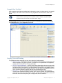
Starting RingMaster from Network Node Manager
You can start RingMaster directly from the main Network Node Manager window.
To start RingMaster from Network Node Manager:
1. Start Network Node Manager. The Network Node Manager window appears.
2. In the main Network Node Manager window, do one of the following:
❑
Select Tools > Trapeze Networks > RingMaster.
❑
Click the Trapeze Networks icon in the toolbar.
❑
Right-click (Macintosh: Control+click) a Trapeze MX, and select RingMaster.
The main RingMaster window appears.
Using the RingMaster Client for Planning
After RingMaster Services have been started on a server, a RingMaster Client can be used to
perform WLAN planning functions.
1. Start the RingMaster Client by doing one of the following:
❑
On Windows systems, use the desktop icon placed by the installer, or select
Start > Programs > Trapeze Networks > RingMaster > RingMaster.
❑
On Linux systems, change directories to:
RingMaster_installation_directory/bin
and enter
./ringmaster.
❑
On Macintosh OS systems, select Finder > Applications > RingMaster, or click the
RingMaster icon in the dock. The RingMaster Services Connection dialog displays.
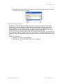
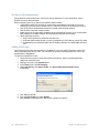
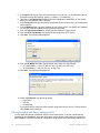
2. Enter the IP address or fully-qualified hostname of the server on which RingMaster Services
are installed. If RingMaster Services is installed on the same machine as the one running
RingMaster Client, enter 127.1.0.1 as the IP address. This is a standard IP loopback address.
3. Specify a service port, if different from the port number in the Service Port listbox.
The port number used by the monitoring service must not be used by another application on the
machine where the monitoring service is installed. If the port number is used by another application,
change the port number on the monitoring service. (Refer to Configuring RingMaster Services.)
4. Click Next to connect to the server.
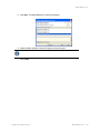
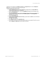
5. If a Certificate Check dialog is displayed, click Accept. If the Open Network Plan option on
the RingMaster Services Connection dialog is selected, the server opens a new (Default)
network plan icon in the Organizer panel at its left side.
2
Introduction to RingMaster 7.4
Copyright © 2011, Juniper Networks, Inc.
Introduction to RingMaster 7.4
RingMaster Client Main Window
RingMaster software presents a Graphical User Interface (GUI) to its users, consisting of a series of
screens, windows, and dialog boxes. In many cases, sample images of these GUI elements have
been included in this publication. The RingMaster GUI allows you to resize these elements, and this
has been done to minimize element illustration sizes in this publication, while retaining all of the
information visible in them. This resizing of screens, windows and dialog results in illustrations that
may differ in appearance from what you may see on your workstation display.
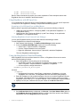
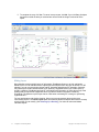
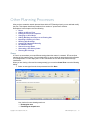
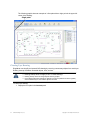
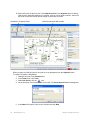
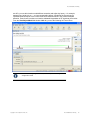
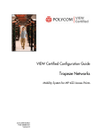
The RingMaster Client presents a Main Window similar to the one shown below.
Menu Bar
Organizer
Panel
❑
❑
❑
❑
❑
❑
❑
Navigation Bar
Tas
Pan
Ser
Content Panel
Alerts and Alarms Panel
I
The Menu bar provides pull-down menus containing selectable items for accessing
administrative tools such as plan management and online Help. For example, to examine
RingMaster logging preferences, select Tools > Preferences and click the Logging tab.
The Navigation bar provides buttons by which you access features and summary views. For
example, you use the Back and Forward buttons to cycle through display selections.
The Organizer panel displays a network tree representing WLAN devices and configurations
on those devices. You can use it to navigate to policy configurations, equipment within your
network, and network sites. When you select a device or configuration in the tree, contextsensitive information about a device or configuration is displayed in the Content panel.
The Content panel displays context-sensitive information about the device or configuration
selected from the tree in the Organizer panel. This information may be in the form of a table, a
floor view, details panels, a four-segment “dashboard” layout Outdoor Area view. From the
Content panel, view Juniper devices and status, verify Juniper device configurations in the
network plan and in the network, and display event logs and rogue detection results.
The Alerts and Alarms panel displays configuration errors, network alarms, rogue detection,
local and network changes. Click on a button or summary to display details.
The Tasks panel displays context-sensitive actions for a Tool button/Organizer selection.
The Server icon indicates the status of the connection between the RingMaster Client and the
host running RingMaster Services.
Copyright © 2011, Juniper Networks, Inc.
Introduction to RingMaster 7.4
3
For additional details regarding the components of the RingMaster Client main window, refer
to “RingMaster User Interface” in the publication RingMaster 7.4 Configuration Guide.
Accessing RF Planning Tools
RingMaster planning tools determine necessary equipment, configuration, and installation locations
based on information provided about WLAN needs. You specify outdoor coverage areas and plan
installations in buildings, internet cafes, student campus locations, or anywhere a wireless network is
needed. When you have added geographical information about a network, you can use RingMaster to
find network clients or rogue devices visually.
To access RF planning tools, select the RF Planning Navigation Bar button and do one of the
following:
❑
If you are adding a new building, click on a site name icon in the Organizer panel and
select Create Building in the Tasks panel. (See Adding Buildings and Floors to an Existing
Site.)
❑
If you are creating outdoor coverage areas, click Create Outdoor Area.
❑
If you are modifying an existing building, click on the plus sign next to a site name to expand it,
then click on the name of the building you want to modify.
Configuration Using Wizards
In many cases, RingMaster provides a series of dialog boxes that guide you through a configuration
process. After completing entries and selections in one dialog box, you click Next or Save and
Continue to proceed with a task. The “wizard” presents the next dialog you should use to proceed, in
the recommended sequence, to complete an overall configuration task. Although there are other ways
to view and/or alter configuration settings later, these wizards are helpful for completing initial setups
using the guidance of wizards designed to enforce best practices.
Configuration Using Dialog Boxes
RingMaster dialog boxes allow you to specify options and perform actions. You can right-click (on
Macintosh it is Control+click) on many objects to display optional actions.
User Interface Details
For a more complete description of the RingMaster GUI, refer to “RingMaster User Interface” in the
publication RingMaster 7.4 Configuration Guide.
Setting Preferences
You can set Network, Tools, RF and Logging preferences.
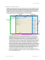
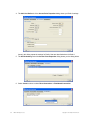
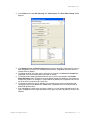
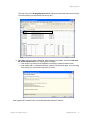
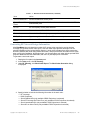
1. Select Tools > Preferences from the RingMaster main menu bar. The Preferences window
is displayed.
The Network tab is displayed first, where you can change the following:
❑
Connect Timeout
❑
Retry Count for Server communications.
4
Introduction to RingMaster 7.4
Copyright © 2011, Juniper Networks, Inc.
Introduction to RingMaster 7.4
You can Reset to restore previous values in this tab or Reset All to reset preferences
to defaults.
Select Close to exit and leave changed values, or click on another tab in the dialog box.
2. The Tools tab is used to select paths to software tools, including:
❑
Telnet Executable
❑
SSH Executable
❑
Browser Executable
❑
AirDefense Executable
3. The RF tab presents a multi-tabbed Preferences dialog box that allows you to select colors to
be used to display items listed in the tabs in the dialog. This includes the following:
❑
802.11a Channel Colors
❑
Data Rate Colors
❑
802.11b/g Channel Colors
❑
RSSI Band Colors
❑
RF Obstacle Colors
❑
Mesh Colors
Copyright © 2011, Juniper Networks, Inc.
Introduction to RingMaster 7.4
5
4. The Logging tab allows you to select items to be saved in logs and later used for reports
generated by RingMaster.
This includes the following:
❑
Log General Events
❑
Log Model Events
❑
Log UI Infrastructure Events
❑
Log Device Interface Events
❑
Log Persistence Events
❑
Log Mapper Events
❑
Log UI Events
❑
Log Transaction Manager Events
❑
Log Network Events
❑
Log Syslog Manager Events
❑
Log Service Events
❑
Log RDBMS Events
There is also a pull-down menu from which you can select reported alarm levels.
These options are:
❑
Critical
❑
Info
❑
Warning
❑
Debug
Getting Help
Click Help from the Main menu bar to access online help and other information:
1. Select Help > Help to display HTML help about configuring and using RingMaster.
6
Introduction to RingMaster 7.4
Copyright © 2011, Juniper Networks, Inc.
Introduction to RingMaster 7.4
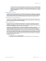
Select Help > Report Problem to report a problem to Juniper Technical Support. This dialog
allows you to report problems to Juniper Networks by filling in particulars and then clicking
Send Now to compose and send an email to Juniper.
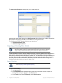
Select Help > About RingMaster to display information about RingMaster as shown below:
Copyright © 2011, Juniper Networks, Inc.
Introduction to RingMaster 7.4
7
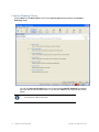
Configuring RingMaster Services
You can change the properties of RingMaster Services.
If a firewall is enabled on the host where you install RingMaster Services, RingMaster
Services cannot communicate with RingMaster Client or with MXs unless the firewall is
configured to allow through traffic for the SSL and SNMP ports (443 and 162 by default).
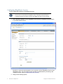
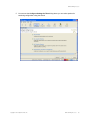
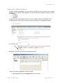
1. Select Services > Setup from the RingMaster main menu bar. RingMaster Services opens
in your default Web browser.
By default, a username and password are not required to access RingMaster Services from
RingMaster Client. You can configure user accounts for administrative, provisioning, and
monitoring access. (Refer to Improved Access Control.)
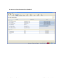
2. Configure the following options:
8
Introduction to RingMaster 7.4
Copyright © 2011, Juniper Networks, Inc.
Introduction to RingMaster 7.4
❑
❑
Trap receiver port is for traps generated by MXs
HTTPS server port is for RingMaster (RM) clients
On each MX in the network plan, you must enable notifications and configure RingMaster
Services as a notification target (trap receiver).
RingMaster Services does not start listening for SNMP notifications from switches until you
save the network plan.
3. Specify security settings in the Key Store area. The Auto-Config IP Subnet Matching option
is used for field replacement of MXs. For information, refer to the RingMaster 7.4 Configuration
Manual. Click Access Control on the left to define user accounts. For more information about
access control, refer to Improved Access Control.
Selecting Monitoring Settings
All monitoring options are enabled by default. You do not need to enable them and you do not need to
specify the switches you want to monitor. However, for RingMaster Services to receive trap data from
MXs, SNMP notifications must be enabled and RingMaster Services must be configured as a
notification target on each of the switches. To start gathering data for monitoring, deploy your
configuration to the network. For information about deploying your configuration, refer to Deploying a
Network Plan.
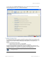
Improved Access Control
Users and Groups
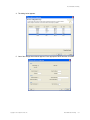
To configure access for users and groups:
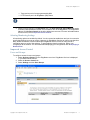
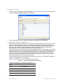
1. Select Services > Setup from the RingMaster menu bar. RingMaster Services is displayed
in your default Web browser.
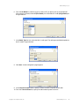
2. Select the Access Control tab.
3. Select Settings and then User Groups.
Copyright © 2011, Juniper Networks, Inc.
Introduction to RingMaster 7.4
9
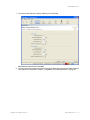
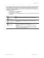
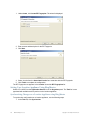
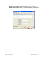
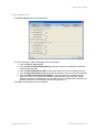
You must add a User Group before you can add Users. Click Add User Group.
You assign a User Group Name and make the following selections:
❑
Check Allow Server Administration to allow this privilege or clear if denying it.
❑
Check Configuratio Privilege Enabled to allow this or clear if denying it.
❑
Select Access Type as Edit or View-only
❑
Select Configuration Access as Full or Scope-restricted (as defined by settings below,
including:
◆ Equipment Scope
◆ Equipment Object
◆ RF Planning Scope
◆ RF Planning Object
❑
Check Monitor Privilege Enabled to allow this or clear if denying it.
❑
Select Plan Access as Full or Scope-restricted (as defined by settings below, including:
◆ Equipment Scope
◆ Equipment Object
◆ RF Planning Scope
◆ RF Planning Object
Click Add.
10
Introduction to RingMaster 7.4
Copyright © 2011, Juniper Networks, Inc.
Introduction to RingMaster 7.4
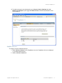
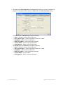
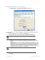
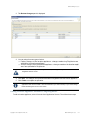
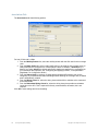
If there is an error, you will see a notice in the dialog box with an explanation:
Make corrections and click Add again.
Copyright © 2011, Juniper Networks, Inc.
Introduction to RingMaster 7.4
11
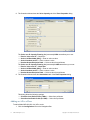
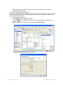
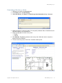
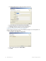
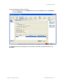
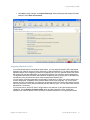
4. Select Settings.
5. Click Add User now that there is a group available.
6. Create Name, select a User Group, assign a Password. Re-enter the Password.
7. Click Add. The new user appears in the list.
8. To remove, click Delete next to the desired user.
9. To reset a password, click Edit.
12
Introduction to RingMaster 7.4
Copyright © 2011, Juniper Networks, Inc.
Introduction to RingMaster 7.4
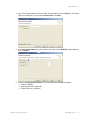
10. To enable and require use of passwords, go to Access Control > Settings and select
Enable log-in Required. (This toggle with Allow all users, which allows password access
to be turned off.)
RADIUS Servers
To configure access for RADIUS Servers:
1. Select Services > Setup from the RingMaster menu bar. RingMaster Services is displayed
in your default Web browser.
2. Select the Access Control tab.
Copyright © 2011, Juniper Networks, Inc.
Introduction to RingMaster 7.4
13
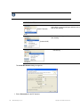
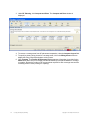
3. Select RADIUS Servers.
Select Enable RADIUS Authentication or clear it to enable or disable it.
Select a Default User Group.
Provide information for Primary RADIUS Server and Secondary RADIUS Server as desired.
Click Save.
Providing Services
A network service is defined by a set of options you configure and deploy on a WLAN. Services are
configured to support various levels of network access. For example, a service configured to support
employee access has options that provide greater access to a network. Services configured for guest
access have limited or no internal network access, but provide Internet connections. A service can be
fully isolated and independent from other services on a WLAN (multi-hosted access is typically
isolated), or can re-use portions of a service configured for some other service. Services may have
authentications such as 802.1X, Web page, MAC address, or “last resort”. They may include
encryptions such as 802.11i, WPA, WEP, or they may be unencrypted.
14
Introduction to RingMaster 7.4
Copyright © 2011, Juniper Networks, Inc.
Introduction to RingMaster 7.4
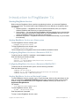
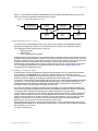
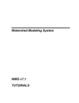
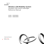
Figure 1–1 describes the process of establishing services, starting with determining the services to
offer. Each step in this process is described in this chapter.
Figure 1–1. Establishing Wireless Services
START
Determine which
Services to provide
Configure
Services
Plan for network
equipment and
coverage
Generate work
order and install
equipment
Optimize
Services
Monitor
Services
Deploy
Services
Understanding Service Types
You need a clear understanding of the service types you will configure with RingMaster before
planning and configuring a network. First, determine which services your organization requires.
The following are three common types of services:
❑
Employee access
❑
Guest access
❑
Voice over Wireless IP (VoWIP)
Employee access is typically secure, encrypted access to a wireless network. Guest access is access
(possibly unencrypted) provided for visitors. If you intend to resell services to other providers, you must
provide multi-hosted access. Determining services you need at the beginning of the planning process
results in collection of configuration data. This data is used to create service profiles and
Authentication, Authorization, and Accounting (AAA) rules for a service. A radio profile is a common
set of configuration parameters to be applied to many AP radios. See Providing Services for
information about configuring services.
Creating A Network Plan
A network plan is used in RingMaster to design a wireless network. An icon representing a network
plan is placed in the Organizer panel. This icon is appears at the top of a hierarchy of icons
representing all your WLAN devices and lists their services, policies, etc. You can better manage and
visualize a network’s topology by creating a detailed and accurate network plan.
You start by creating a device-oriented (MX and AP) view of your network with geographic information
for your site — no floor dimensions, building material information, or RF obstacle information. You
provide geographic information by adding floor dimensions, RF coverage area, and attenuation
information, such as elevator shafts or internal concrete walls.
If you want the benefits of network monitoring and visualization, you create a detailed network plan.
This is done by importing building and floor plans into RingMaster, defining RF obstacles and quality
of coverage (traffic engineering parameters) you want for specific RF coverage areas.
A network plan is a repository for all hardware, site and configuration details for a single or multi-site
network. This information is stored on your RingMaster Services server. You may have individual
network plans for networks in multiple countries, in which case regulatory rules on channels, power
levels, etc. are different. You may have more than one Network Plan to accommodate these
differences or you can choose to have one plan with multiple sites.
Each network plan may have a number of sites (campuses or cities) in which there are one or more
buildings and associated floors, and possibly Outdoor Areas. You should create a Network Plan name
that is familiar to your IT team.
To create a network plan:
Copyright © 2011, Juniper Networks, Inc.
Introduction to RingMaster 7.4
15
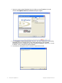
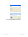
1. Connect to a host running RingMaster Services. When you start RingMaster, the main
window and RingMaster Services Connection dialog box appear.
2. In the RingMaster Services Connection dialog box, enter the IP address of a host running
RingMaster Services, optionally enter a user name and password, and click Next.
If RingMaster Service is installed on the same machine as RingMaster, enter 127.1.0.1 as an
IP address. This is a standard IP loopback address.
3. You will see the dialog below as the connection is approved and made.
16
Introduction to RingMaster 7.4
Copyright © 2011, Juniper Networks, Inc.
Introduction to RingMaster 7.4
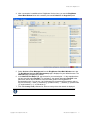
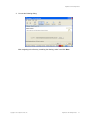
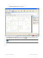
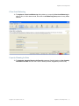
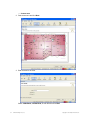
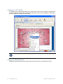
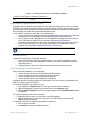
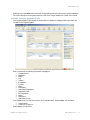
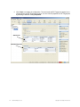
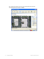
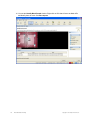
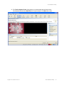
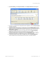
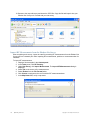
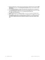
4. After a connection is established to a RingMaster Services host, you see the RingMaster
Client Main Window below with a network plan named Default in the Organizer panel.
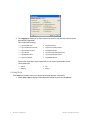
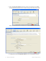
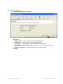
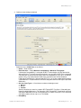
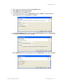
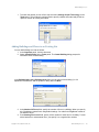
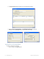
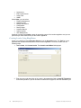
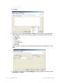
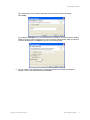
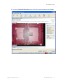
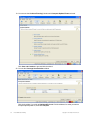
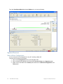
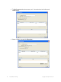
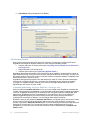
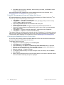
5. Select Services > Plan Management from the RingMaster Client Main Window menu bar.
The RingMaster Services Plan Management page is displayed in your default browser. The
New Plan page is displayed by default.
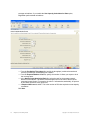
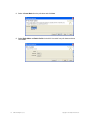
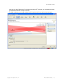
6. In the Network Plan Name field, type a name for your network plan — in the example above
we have used the name DocPlan. For consistency, the network plan name DocPlan is the
plan name used in later illustrations in this and other guides in the RingMaster 7.4
documentation suite. You can use 1 to 60 alphanumeric characters with no spaces, tabs, or
any of the following — slash (/), backslash (\), quotation marks (“ ”), asterisk (*), question mark
(?), angle brackets (< >), or vertical bar (|).
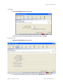
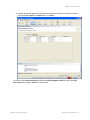
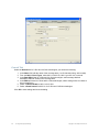
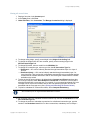
7. From the Country Code pull-down list, select a country where the network is deployed.
You must select a country code before continuing. A network plan is limited to one country, since
it supports only one country code for MXs.
Copyright © 2011, Juniper Networks, Inc.
Introduction to RingMaster 7.4
17
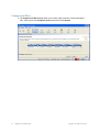
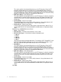
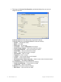
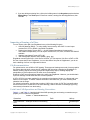
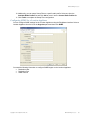
8. Select the Open this plan? check box to open a plan in RingMaster.
9. Click Create to create this new network plan.
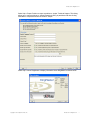
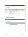
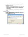
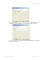
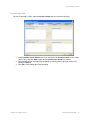
10. Wait while the server initializes:
18
Introduction to RingMaster 7.4
Copyright © 2011, Juniper Networks, Inc.
Introduction to RingMaster 7.4
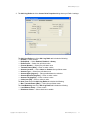
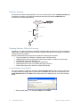
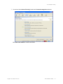
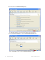
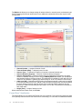
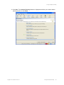
11. The Server information is displayed.
After a short time, the client you started in step 8 receives a notification that the plan has changed.
Copyright © 2011, Juniper Networks, Inc.
Introduction to RingMaster 7.4
19
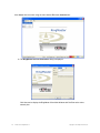
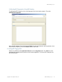
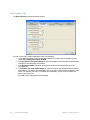
Click Close, then reconnect using the main window File menu Connect item:
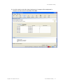
12. The RingMaster Services Connection dialog is displayed.
Click Next and to display the RingMaster Client Main Window with DocPlan as the active
network plan.
20
Introduction to RingMaster 7.4
Copyright © 2011, Juniper Networks, Inc.
Introduction to RingMaster 7.4
Example Plan “DocPlan”
After creating a network plan and adding basic information to create a wireless network, you can add
sites, buildings, and outdoor wireless networks using RingMaster tools described in detail in this
Guide.
You can import floor plans and create coverage areas even if you do not have a planning
license. However, a planning license is required to create RF obstacles, compute and place
equipment, assign radio channels, and optimize power settings.
Example dialog box entries used to create the illustrations in this guide will add to the network plan
named DocPlan shown in the Organizer panel below.
Starting Network Planning
The following are three techniques you can use to start your wireless network:
❑
RF Auto-Tuning — This technique lets you use default auto tuning features to select power and
channel settings for RF signals in your RF coverage area. You upload MXs into RingMaster,
configure APs, enable RF Auto-Tuning, and deploy.
❑
RF Auto-Tuning with Modeling — Like RF Auto-Tuning, this technique lets you set auto tuning
features to adjust power and channel settings for providing RF signals to a coverage area. You
can enhance auto tuning feature by providing modelling information for a geographic location.
By providing information about buildings and floors, you add details into RingMaster that allow
you to visualize a network’s topology and thus provide monitoring at a site.
❑
RF Planning — This is a technique you use to create a network plan providing powerful
monitoring and visualization benefits. Unlike RF Auto-Tuning or RF Auto-Tuning with Modelling,
you do not rely on the auto tuning feature. Instead, you fully model a geographic location with
information about floors and specify RF coverage areas and RF obstacles.
Copyright © 2011, Juniper Networks, Inc.
Introduction to RingMaster 7.4
21
RF Auto-Tuning
You perform the following steps when using the RF Auto-Tuning technique:
❑
Physically place MXs and the APs in desired locations.
❑
Upload an MX configuration and deploy it.
❑
Enable the RF Auto-Tuning feature.
This allows you to install MXs and APs and observe how a network operates. An RF Auto-Tuning plan
is best for networks containing fewer APs.
RF Auto-Tuning with Modeling
To use RF Auto-Tuning with Modelling techniques, you add to the RF Auto-Tuning technique by
providing geographical modelling for buildings, floors, and RF coverage areas. You add RF obstacle
information for obstacles like concrete walls, windows, and elevator shafts that affect attenuation (the
quality of RF signals emitted from and received by the APs). By adding geographical modelling, you
manage a network in the context of geographical information. For example, you can manage a
network viewed overlaid on a floor plan rather than managing an abstract logical group of MXs and
APs.
RF Planning
To perform RF Planning, you provide information about your buildings by importing AutoCAD DXF™,
AutoCAD DWG, JPEG, or GIF floor plan files into RingMaster. As you import floor plans, you modify
them to add or remove RF obstacles. You define RF obstacles by specifying an attenuation factor in
decibels for each obstacle. In addition, RingMaster includes a library of attenuators for building
obstacles. The library includes doors, walls, ceilings, and other physical obstructions you select.
RingMaster factors in the impact of these objects on Radio Frequency (RF) signals flowing through a
given site.
If a network contains third-party or pre-installed APs, enter information for these APs so RingMaster
takes these APs into account when calculating placement (and optionally, channel and power settings)
of Juniper APs.
Use of this technique has the following benefits:
❑
Instead of making a “best guess” of how many APs are required for a desired coverage and
where they should be placed, RingMaster calculates how many APs you need and specifies
their locations to provide optimum performance.
❑
You generate a deployable work order to help installers place MXs and APs.
❑
You automatically receive a deployable configuration that includes optimum power and channel
settings.
❑
You enjoy more accurate monitoring options and network visualization based on the additional
geographic modeling information loaded into RingMaster.
Recommended Planning Method
Detailed network plans provide better management and monitoring of a network. However, there are
other requirements you should consider. We recommend using RF Auto-Tuning if you are installing
APs without consideration of blanket coverage, throughput concerns, or the number of users for whom
services are provided. RF Auto-Tuning is ideal for small areas, such as coverage that only requires a
few APs or widely dispersed areas in a building, such as conference rooms.
You use RF Auto-Tuning with Modelling techniques where you want to improve monitoring of a
wireless network in terms of buildings, floors, or coverage areas. You may locate inaccurate or
incomplete building and floor plans (perhaps only a JPEG file), but with geographic modelling of your
site you improve your ability to visualize your network.
You can use RF Planning tools provided in RingMaster to initially plan work. You may have multiple
constituencies of users to consider. For example, users who are mobile and wireless have specific
throughput and bandwidth needs. One group of users might be mobile and require high throughput
performance, while another group is more stationary and requires less throughput. You might be
planning future capacity and need to add detailed information about your site to plan for the future.
22
Introduction to RingMaster 7.4
Copyright © 2011, Juniper Networks, Inc.
Introduction to RingMaster 7.4
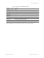
The table below provides guidelines to help you determine an appropriate planning technique for your
organization.
Table 1– 1. Selecting Appropriate Planning Techniques
Question
If yes, use
If No, use
Do I have adequate time to add geographic RF Auto-Tuning with
modelling and RF obstacle information?
Modelling
RF Auto-Tuning
Can I locate accurate building and floor
plans?
RF Planning or RF
Auto-Tuning with
Modelling
RF Auto-Tuning with
Modelling
Do I need to plan for capacity of users or
quality of coverage (traffic engineering
concerns) for certain users?
RF Planning
RF Auto-Tuning or RF
Auto-Tuning with Modelling
Do I need to visualize coverage accurately? RF Planning
RF Auto-Tuning or RF
Auto-Tuning with Modelling
Do I need to locate users?
RF Planning or RF
Auto-Tuning with
Modelling
RF Auto-Tuning
Do I need to locate rogue APs?
RF Planning or RF
Auto-Tuning with
Modelling
RF Auto-Tuning
Do I want to better monitor my wireless
network in terms of buildings, floors, or
coverage areas?
RF Planning or RF
Auto-Tuning with
Modelling
RF Auto-Tuning
If RF Planning does not fit your requirements now, you can use it in the future when there is a need,
time, and floor plans. You can leverage data in RF Auto-Tuning and convert RF measurements to
configured baseline values for planning.
RF Plan Optimization
Optimization involves importing of RF measurement data into an RF model to improve the accuracy of
the model. A network plan contains configuration settings to determine the performance of a wireless
network. Optimization of an RF model leads to a more successful RF plan. This plan provides an
accurate visualization of RF coverage, statistics for monitoring, and an ability to accurately plan for and
improve network performance.
You optimize a network based on user and network statistics gathered from:
❑
Monitoring data in RingMaster
❑
A site survey
RF measurement data you gather in RingMaster is used to optimize the RF model of a floor. You can
make configuration changes in the software to improve signal strength and coverage for groups or
individuals, modify AP locations, or add additional equipment to your wireless network if statistics
indicate your network has outgrown the support provided by the current deployment of MXs and APs.
You can import RF measurement data based on a site survey done outside of RingMaster. Refer to
Optimizing an RF Coverage Model for general guidelines about performing a site survey.
Copyright © 2011, Juniper Networks, Inc.
Introduction to RingMaster 7.4
23
24
Introduction to RingMaster 7.4
Copyright © 2011, Juniper Networks, Inc.
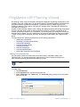
RingMaster’s RF Planning Wizard
RF planning is done using site information provided to RingMaster. By defining network plans, sites,
buildings, floors and outside areas, you provide RingMaster information regarding a network and its
geographical and/or organizational boundaries. For wireless networks, Radio Frequency (RF)
Planning is done first. This involves configuring RF coverage areas, and adding RF obstacle and
third-party AP information.
Creation of sites, buildings, outdoor areas, locating and adding equipment and making configuration
choices is all done using a series of dialog boxes that function as a “wizard” to guide you in the
process of planning a WLAN for your organization. This wizard guides you through RF Planning as
described in this chapter. There are optional ways of performing these planning functions available
“outside” of the wizard for additions, selections and changes as described in later chapters of this
Guide.
The major steps in RF Planning as directed by the RF Planning Wizard are:
❑
Adding Site Information
❑
Importing or Drawing Floor Details
❑
Creating RF Obstacles
❑
Creating Coverage Areas
❑
Compute and Place
❑
Channel Assignment
❑
Compute Optimal Power
❑
Steps After Using RF Planning Wizard
Adding Site Information
Site information includes information about an overall campus, individual buildings, and
individual floors. You describe attenuation characteristics in these locations and specify the
traffic engineering needs (bandwidth and reliability) of users.
RingMaster commits your work into a network plan only when you click Finish, not when you click
Next.
To create a site:
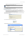
1. Click RF Planning.
2. In the Organizer panel, click the network plan icon.
3. Select Create Site in the Tasks panel. The Create Site dialog prompts you for information
about the new site.
Copyright © 2011, Juniper Networks, Inc.
RingMaster’s RF Planning Wizard
25
4. In the Site Name field, type a name for the site (1 to 80 alphanumeric characters, with no
spaces or tabs), select feet or meters for units with the pull-down menu, and click Next.
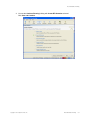
5. In the Regulatory Domain dialog, select from the Country Code pull-down menu. Click Next.
6. In the Channel Set dialog, add and delete channels to Current Channels to select a set of
operating channels for 2.4 GHz and 5 GHz you plan to use and click Next.
7. In the Building and Outdoor Areas dialog, select a Number Of Buildings and Number Of
Outdoor Areas. When you specify the number of buildings and Outdoor Areas for a site,
26
RingMaster’s RF Planning Wizard
Copyright © 2011, Juniper Networks, Inc.
RingMaster’s RF Planning Wizard
RingMaster creates buildings and Outdoor Areas using default settings. You can edit
buildings or Outdoor Areas that RingMaster creates.
This step is optional, as buildings and outside areas can be added later using Tasks panel
selectable items.
Click Finish to save settings and close the dialog.
Customizable Channel Set
The channel set used for RF Planning is customizable for both bands — 2.4 GHz and 5 GHz.
❑
The 2.4 GHz channel set is automatically converted into a new format when an old plan is
opened. When a new plan is created, default channels are set in the channel set.
❑
The 5 GHz channel set is automatically added when a new plan is created or opened in 7.4.x.
It will contain all the available channels for a given country.
You are allowed to select valid channels in a country into a channel set. On the Network Plan level,
both channel sets are displayed.
You can customize the channel set via the following tasks:
The Country Code dialog allows you to select a country using a pull-down menu:
Copyright © 2011, Juniper Networks, Inc.
RingMaster’s RF Planning Wizard
27
The Channel Set Properties dialog allows you to modify channels.
A Site has the same display channels in its Site Properties dialog, allowing you to edit a Channel Set.
Make desired changes and click OK, or click Cancel if no changes are made.
The following tasks in RF Planning utilize the new channel set:
❑
Compute and Place Task
❑
Channel Assignment Task
Importing or Drawing Floor Details
In RingMaster 7.4, starting any of the tasks on an Organizer panel tree floor icon starts the
RF Planning wizard to help you complete planning steps in the proper sequence. Clicking to
import a floor plan starts the RF Planning wizard, whose use is always recommended.
To add information for a floor, import a drawing of the floor or use the graphics tools in RingMaster to
draw the floor. After importing or drawing a floor, specify RF characteristics of the floor and the
attenuation of obstacles such as walls, doors, windows, etc. The attenuation of an object indicates how
the object affects an 802.11 radio signal. RingMaster uses attenuation information when calculating
how many APs are needed and where to place them to provide desired wireless coverage. The
following sections describe how to import or draw a floor.
Import Drawing
Before importing a drawing into RingMaster, you should follow the procedures in the
section Preparing a Drawing Before Importing.
To import a floor drawing:
1. click RF Planning.
2. In the Organizer panel, expand a building, then click on the name of a floor to import its
drawing. The floor layout appears in the Content panel.
3. In the Tasks panel, under RF Planning, select Import Layout.
28
RingMaster’s RF Planning Wizard
Copyright © 2011, Juniper Networks, Inc.
RingMaster’s RF Planning Wizard
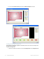
4. You see the following dialog:
After navigating to the directory containing the drawing, select it and click Next.
Copyright © 2011, Juniper Networks, Inc.
RingMaster’s RF Planning Wizard
29
5. You can now select the scaling of the drawing.
Adjusting the Scale of a Drawing
If you imported a DWG or DXF drawing, you must adjust the scale of the drawing because the units
used in these drawings might not have a one-to-one correspondence to meters and feet. To adjust the
scale of the drawing, you draw a line between two points of known distance and adjust the
measurement.
You can accept the scale defined in the CAD file by clicking Next, or you can set it manually as
described below.
To adjust the scale manually:
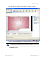
1. Display the floor plan in the Content panel.
2. Drag to create a line between two points. A dialog box appears.
3. In the dialog box, type the actual distance between the two points.
4. Click OK then click Next.
30
RingMaster’s RF Planning Wizard
Copyright © 2011, Juniper Networks, Inc.
RingMaster’s RF Planning Wizard
Cropping a Drawing
You can crop a drawing to remove unneeded space and objects around a floor. For example, if a
drawing includes parking lot information, you can remove the parking lot by cropping.
All objects outside of the selected area are permanently removed. The drawing can be re-imported to
correct this problem, but all planning must be re-done.
To crop a drawing:
1. Display a floor plan in the Content panel.
2. Click
on the Tools panel.
3. Click and diagonally drag the cursor over the area you want to keep.
4. Release the mouse button. A warning is displayed.
Copyright © 2011, Juniper Networks, Inc.
RingMaster’s RF Planning Wizard
31
5. To complete the crop, click Yes. To cancel a crop request, click No. If you click Yes, all objects
and space outside the area you selected are removed and the image is resized to fill the
space.
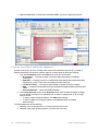
Hiding Layers
Most drawings contain multiple layers of information. RingMaster allows you to hide, add and/or
delete layers. You can add and remove objects and move objects from one layer to another. For RF
planning, you can convert existing objects into RF obstacles and add new RF obstacles. Generally,
only some layers contain details relevant to RF planning. RingMaster allows you to hide layers to
simplify a drawing. RingMaster performs RF calculations with information in visible layers only. Each
drawing that you import into RingMaster has a layer 0 that contains information created by
RingMaster. RingMaster requires layer 0 to be visible when calculating RF coverage or performing
rogue detection.
For best performance and simpler planning, hide or remove unnecessary layers and remove
unnecessary objects. The Clean Layout option automatically deletes all objects that meet the cleanup
criteria, which you can modify. (See Cleaning Up a Drawing.) You also can select and delete
individual objects.
32
RingMaster’s RF Planning Wizard
Copyright © 2011, Juniper Networks, Inc.
RingMaster’s RF Planning Wizard
You now can hide unnecessary drawing layers by clearing the checkbox next to the layer name.
When you have hidden the layers you do not want to see, click Next. You can, optionally,
perform functions described in Working with Drawings. When this process is completed, click
Next to go to the Continue Planning? dialog.
Copyright © 2011, Juniper Networks, Inc.
RingMaster’s RF Planning Wizard
33
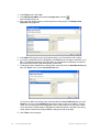
Continue Planning? Dialog
Clicking Next from the Hide Layers portion of the Import Layout wizard presents the Continue
Planning? dialog:
You can click Save and Continue and you will proceed to Create RF Obstacles as noted by
the arrow and the selected radio button, or you can click Finish to save the plan and exit the
wizard.
Clicking on a radio button other than the one with the arrow takes you to that function
“out of sequence” relative to the wizard.
34
RingMaster’s RF Planning Wizard
Copyright © 2011, Juniper Networks, Inc.
RingMaster’s RF Planning Wizard
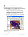
Creating RF Obstacles
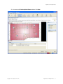
If you click Save and Continue without changing the selected radio button, you see the Create RF
Obstacles dialog.
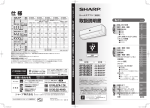
Use the pull-down menus to select the characteristics of objects. The example above shows the
selection of RF WALL BRICKS to be Brick (3.5”). Make selections and click Next. You will see a
Progress dialog that shows when settings are 100% saved. Click Next.
RingMaster can automatically map a layer to a pre-defined RF Obstacle Type.
See Tools > RF Obstacle Types Library.
Tip
If you do not want to assign any obstacle to a layer at this point, set the RF Obstacle Type to None and
the layer is skipped.
Copyright © 2011, Juniper Networks, Inc.
RingMaster’s RF Planning Wizard
35
The progress of obstacle programming is displayed:
36
RingMaster’s RF Planning Wizard
Copyright © 2011, Juniper Networks, Inc.
RingMaster’s RF Planning Wizard
You once again see the Continue Planning? dialog, this time with an arrow pointing to the selected
Create Coverage Area radio button. Click Save and Continue.
Creating Coverage Areas
RF coverage areas are areas in a network for which RF coverage is defined. As you configure an RF
coverage area, you consider bandwidth requirements and the number of users. You define a coverage
area on a floor plan using a coverage area drawing tool. Most shapes for a coverage area are
possible.
However, the following restrictions apply:
❑
A shape where two sides intersect is not permitted.
❑
A shared coverage area with a partial intersection is not supported.
RingMaster supports sharing of coverage areas if one area is completely within a larger area. For
example, you might want 802.11a and 802.11b coverage in a conference room that is part of a larger
coverage area with 802.11a coverage. APs are shared only in the overlapped area.
When you draw a coverage area, it aligns to the grid to provide a whole number for width
and height of the shape.
Copyright © 2011, Juniper Networks, Inc.
RingMaster’s RF Planning Wizard
37
1. The Create Coverage Area dialog is displayed:
In the Tasks panel under Create Area, you can click on the
icon to accept the default coverage
area in the imported file or create a custom area as described below.
Drawing of custom areas is terminated via a right click, otherwise you may create an overlapping side.
38
RingMaster’s RF Planning Wizard
Copyright © 2011, Juniper Networks, Inc.
RingMaster’s RF Planning Wizard
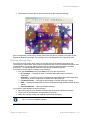
2. In the example below an area was drawn by using the mouse to draw the area shown.
Click Next.
Copyright © 2011, Juniper Networks, Inc.
RingMaster’s RF Planning Wizard
39
3. Select a Coverage Area Identifier and frequency bands to be supported, then click Next.
Coverage areas can be planned for 802.11 wireless coverage on the 2.4Ghz, 5Ghz, or both.
Select an area Name and check use of the 5 GHz or 2.4 GHz Band (or both) and click Next.
4. The dialog above presents Coverage Area Options for you to make additional selections.
40
RingMaster’s RF Planning Wizard
Copyright © 2011, Juniper Networks, Inc.
RingMaster’s RF Planning Wizard
Enter a name for both 2.4 and 5 GHz areas.
In the Rate Selection list for each technology, select Maximize Compatibility or
Maximize Throughput.
◆ If Maximize Compatibility is selected, 11n clients will still be able to connect at 11n data
rates. Lower data rate will be used to plan, so that floor can be covered at legacy rates.
This limits overall throughput, as even though 802.11n is supported, data rates are limited to legacy rates for compatibility. Also, 802.11n specific options, like using wide channels and short guard intervals, are disabled.
◆ If Maximize Throughput is selected, only 802.11n is set as the supported technology
type and all 802.11n optimizations will be leveraged to achieve the highest possible data
rates.
◆ If Custom is selected, 802.11 client Types check boxes are available for use in both 5
and 2.4 GHz areas, and 5 GHz Channel Width can be set to either 20 MHz or 40 MHz.
❑
Select 802.11 Client Types for both the 5 GHz and 2.4 GHz areas
Specify whether you want to support 802.11a, 802.11b, 802.11g, and 802.11n clients.
Selected types impact available data rates. For example, if 802.11a and 802.11n are
both selected, the highest data rate you can use for planning is 54 Mbps. If only
802.11n is selected, the highest data rate you can use is 300 Mbps.
❍ In the Rate [Mb/s] pull-down menu, select a rate for each band used.
This value specifies the desired data rate to use for RF planning. When the RF
Planning wizard computes the number of APs required and chooses the best
location for each AP, it aims to achieve the highest possible coverage of the area at
the selected data rate. Hence, selecting a higher data rate results in more APs being
placed. You can then visualize RF coverage at all data rates.
❑
Select a Channel Width for 5 GHz.
This option allows the use of 40 Mhz (wide) channels for 802.11n. Using wide
channels will enable higher data rates.
❑
Select Guard Intervals for both the 5 GHz areas
This option allows the use of a short guard interval for 802.11n. Using a short guard
interval will enable slightly higher data rates (about 10%). A short guard interval is
not recommended for outdoor areas, or large open indoor areas.
❑
Enter desired RSSI Values for both the 5 GHz and 2.4 GHz areas.
This value specifies the desired RSSI to use for RF Planning. It is directly related to
the data rate, in a manner where changing one value will impact the other. If you
specify an RSSI value, the lowest data rate required to achieve the RSSI will be
configured.
Click Next.
❑
❑
Copyright © 2011, Juniper Networks, Inc.
RingMaster’s RF Planning Wizard
41
Floor Options
5. You now see the Floor Options dialog.
You select functions you want to perform and click Next.
The paragraphs below assume all were checked and then Next was selected.
42
RingMaster’s RF Planning Wizard
Copyright © 2011, Juniper Networks, Inc.
RingMaster’s RF Planning Wizard
AP Height
6. Selecting AP Height displays the following:
Select the ceiling height and default MP (AP) placement height. Click Next.
Default Models
7. Optional: Default Models dialog appears:
8. To change the default MX model, select a model from the MX Model pull-down menu.
Copyright © 2011, Juniper Networks, Inc.
RingMaster’s RF Planning Wizard
43
9. To change the default AP model, select a model from the Default AP Model pull-down menu.
10. To change the AP Connection Type, select one of the following types from the AP
Connection Type pull-down menu:
❑
Direct — APs directly attached to dedicated MX ports.
❑
Distributed — APs indirectly attached through intermediate Layer 2 or Layer 3 devices.
❑
Distributed (Auto) — APs indirectly attached through intermediate Layer 2 or Layer 3
devices that receive their configuration automatically using a profile that assigns a
Distributed AP number and name to the AP from among unused valid AP numbers
available on the MX.
❑
Power Mode — Select AUTO or HIGH. Valid choices are Auto and High Power. For
Auto, the AP will detect the power automatically and depending on the power it will use
2 x 3 or 3 x 3 antennas. For High power it will always use 3 x 3.
Click Next.
Redundant Connections
11. The Optional: Redundant Connections dialog is displayed. Select whether the system
should Compute Redundancy, specify an AP Connection Type, and use the scrolling list to
select a Redundancy Level, then click Next.
44
RingMaster’s RF Planning Wizard
Copyright © 2011, Juniper Networks, Inc.
RingMaster’s RF Planning Wizard
Client Load Balancing
12. The Optional: Client Load Balancing dialog allows you to specify Client Load Balancing for
either 5 GHz, 2.4 GHz band or both, and enter a Load Balancing Group name for any bands
selected.
Capacity Planning for Data
13. The Optional: Capacity Planning for Data dialog appears. Specify whether to Use Capacity
Calculation for Data at 5 GHz or 2.4 GHz or both. By default, RingMaster performs only
Copyright © 2011, Juniper Networks, Inc.
RingMaster’s RF Planning Wizard
45
coverage calculations. If you enable the Use Capacity Calculation for Data option,
RingMaster performs data calculations.
From the Per Station Throughput list, specify the throughput (combined transmit and
receive) in kilobits per second (Kbps) for a station.
❑
From the Expected Station Count list, specify the number of clients you expect to be in
the coverage area.
❑
In the Station Oversubscription Ratio list, select the ratio for the average transmit
behavior of the stations. The station oversubscription ratio is the ratio of active clients
compared to total clients. For example, the ratio 5:1 indicates that, statistically, 20 percent
of the clients are active at any given time.
❑
A Required AP Count is shown. This is the number of APs that required to meet capacity
constraints.
Click Next.
❑
46
RingMaster’s RF Planning Wizard
Copyright © 2011, Juniper Networks, Inc.
RingMaster’s RF Planning Wizard
Capacity Planning for Voice
14. The Optional: Capacity Planning for Voice dialog appears.
To calculate AP placement and configuration based on both coverage and on capacity for
voice over IP, enable Plan for Voice over IP. By default, RingMaster performs only coverage
calculations. If you enable the Plan for Voice over IP option, RingMaster calculates both.
❑
From the Active Call Bandwidth list, specify the amount of bandwidth in kilobits per
second (Kbps) that you expect for each call.
❑
From the Active Handsets per AP list, specify the number of voice over IP phones for
each AP.
❑
From the Expected Handset Count list, specify the number of voice over IP phones you
expect to be in the coverage area.
❑
From the Handset Oversubscription Ratio list, select the ratio for the average transmit
behavior of the voice over IP phones. The handset oversubscription ratio is the ratio of
active handsets compared to total handsets. For example, the ratio 4:1 indicates that,
statistically, 25 percent of the voice over IP phones are active at any given time.
Click Next.
Copyright © 2011, Juniper Networks, Inc.
RingMaster’s RF Planning Wizard
47
Mobility Domain, Radio Profile, Wiring Closet(s), Preferred
Device
15. The Optional: Mobility Domain, Radio Profile, Wiring closet(s), Preferred Device dialog
appears.
From the Mobility Domain pull-down menu, select a Mobility Domain containing the APs in
this coverage area.
❑
In the Radio Profile pull-down menu, select the radio profile used for 5 GHz and 2.4 GHz
coverage areas. Profiles available depend on the Mobility Domain selected. The selected
profile applies to all radios associated with a coverage area. If you type the name of a
radio profile that does not exist, RingMaster creates one with this name.
❑
In the Wiring Closet pull-down menu, select the wiring closet with the MXs to be
connected to shared APs. If APs are directly connected to MXs, a wiring closet is required.
If all APs in a coverage area are indirectly connected to MXs through a network, a wiring
closet is not required.
❑
In the Redundant Wiring Closet pull-down menu, select a wiring closet providing
redundant connection to APs. This is required for directly connected APs if you want APs
to have redundant connections. Otherwise, this is not required.
❑
In Preferred Devices, select and move appropriate Available Devices to the Current
Devices list.
Click Next.
Refer to the descriptions of Mobility Domains in the publication RingMaster 7.4 Configuration
Guide.
48
RingMaster’s RF Planning Wizard
Copyright © 2011, Juniper Networks, Inc.
RingMaster’s RF Planning Wizard
16. The Continue Planning? dialog appears with Compute and Place highlighted.
Click Save and continue.
Copyright © 2011, Juniper Networks, Inc.
RingMaster’s RF Planning Wizard
49
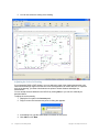
Compute and Place
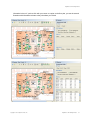
17. The Compute and Place dialog allows you to select areas in which to compute and place
APs. Select items in the Compute Layout column and click Compute.
50
RingMaster’s RF Planning Wizard
Copyright © 2011, Juniper Networks, Inc.
RingMaster’s RF Planning Wizard
18. After a the server does computations, initial AP placement is displayed. Click Next.
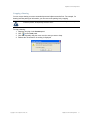
19. You now see the Continue Planning? dialog with Assign Channels selected. Click Save and
Continue to proceed or Finish to exit the wizard,
At any Continue Planning? dialog, you can select an item other than the one with the arrow, but this
removes this process from the wizard and, depending on the status of other settings, may result in errors.
Select Save and Continue.
Copyright © 2011, Juniper Networks, Inc.
RingMaster’s RF Planning Wizard
51
Channel Assignment
20. The Floor Selection dialog is displayed:
Selections are:
❑
Begin On Floor — Floor at which to begin channel assignment
❑
End On Floor — Floor at which to end channel assignment
❑
Technology — Technologie(s) for which channels are to be assigned
❑
Use Cross-Floor Channel Information — Enable/disable use of cross-floor channel
information
❑
Disable Auto-Channel — Enable/disable use of auto-channel feature
Click Next.
52
RingMaster’s RF Planning Wizard
Copyright © 2011, Juniper Networks, Inc.
RingMaster’s RF Planning Wizard
21. Channel assignment progress is displayed and a delay occurs while this process completes
and then displays Done in the Status area. Click Next.
You now see the Continue Planning? dialog with Compute Optimal Power selected. Click Save
and Continue to proceed or Finish to exit the wizard
Copyright © 2011, Juniper Networks, Inc.
RingMaster’s RF Planning Wizard
53
Compute Optimal Power
22. The Coverage Area Selection dialog is displayed. Select Compute box(es) for 2.4 and 5 GHz
frequencies and Optimize AP Count if desired. Click Compute to proceed.
54
RingMaster’s RF Planning Wizard
Copyright © 2011, Juniper Networks, Inc.
RingMaster’s RF Planning Wizard
23. You next see a Finalize Optimal Power window. Click Next.
Copyright © 2011, Juniper Networks, Inc.
RingMaster’s RF Planning Wizard
55
24. This wizard is now complete. You are presented with a dialog listing Next Steps... indicating
typical steps you should perform after using the RF Planing Wizard.
Read and note these suggestions and click Finish.
56
RingMaster’s RF Planning Wizard
Copyright © 2011, Juniper Networks, Inc.
RingMaster’s RF Planning Wizard
Accessing Information from Floor View
During the RF Planning process, APs are placed on floor plan drawings, and floor plan views provide
an excellent means for accessing information about individual APs. The example below demonstrates
some of these features:
Clicking on an AP provides information near its icon as well as in the Properties area in the bottom left
of the window. There are also labels on the 11A and 11G coverage areas that allow you to view
properties of each AP or coverage area individually.
For more detail on Content panel Floor Plan View icons, refer to “Content Panel Icons” in the
RingMaster 7.4 Configuration Guide.
Information displays and menus available with a right-click when an AP is selected and highlighted are
shown in the example below:
Copyright © 2011, Juniper Networks, Inc.
RingMaster’s RF Planning Wizard
57
You can also click on a coverage area to see a pull-down as well. The icons above a floor view will
indicate their functions when you pause your cursor over them as shown in the example (Toggle AP
Label On/Off) at the right below.
There are a number of RF Planning tools available in the Tasks panel shown by clicking on the
Enable/Disable RF Measurements mode icon
as shown below:
This changes the Tasks panel to add Measurement Mode items shown below. The illustration below
shows the Measurement Mode items RF Point, RSSI Options, 802.11a and 802.11b/g areas without
58
RingMaster’s RF Planning Wizard
Copyright © 2011, Juniper Networks, Inc.
RingMaster’s RF Planning Wizard
information in them. If you then click with your cursor on a point on the floor plan, you see the second
illustration with information relevant to the point where you clicked.
Copyright © 2011, Juniper Networks, Inc.
RingMaster’s RF Planning Wizard
59
Visualizing RF Coverage
After you have done this much RF Planning, you can visualize RF Coverage at various data rates
using the Tasks panel item RF Coverage.
60
RingMaster’s RF Planning Wizard
Copyright © 2011, Juniper Networks, Inc.
RingMaster’s RF Planning Wizard
In a floor view, click on Views > RF Coverage > (Select Technology) and you will see somethong like
the example below:
Steps After Using RF Planning Wizard
There are several steps typically required after the RF Planning wizard is finished.
These steps involve the following:
❑
Update MX Configuration
Refer to Configuring MX System Parameters in the publication RingMaster 7.4 Configuration
Guide.
❑
Update AP Configuration
Refer to Viewing and Changing Access Point Settings in the publication RingMaster 7.4
Configuration Guide.
❑
Deploy Configuration
Refer to Completing Configuration and Deploying in the publication RingMaster 7.4
Configuration Guide.
❑
Generate Work Order
Refer to Generating a Site Survey Order or Generating an Ekahau Site Survey Work Order in
this Guide.
❑
Optimize RF Plan
Refer to Chapter , “Optimizing an RF Plan,” on page 1.
Copyright © 2011, Juniper Networks, Inc.
RingMaster’s RF Planning Wizard
61
62
RingMaster’s RF Planning Wizard
Copyright © 2011, Juniper Networks, Inc.
Other Planning Processes
After you have created a network plan and sites with the RF Planning wizard, you can add and modify
the plan. This chapter describes procedures for a number of “post-wizard” activities.
Descriptions in this chapter cover the following:
❑
Zones
❑
Adding an AP to a Floor
❑
Editing Access Point Properties
❑
Changing an AP’s Model
❑
Adding Buildings and Floors to an Existing Site
❑
Importing a Drawing of a Floor
❑
Working with Drawings
❑
Creating RF Obstacles Manually
❑
RF Obstacle Library
❑
Shared Coverage Areas
❑
Generating a Site Survey Order
❑
Planning RF Coverage
Zones
A Zone is an area where you want different settings than other areas in a network. RF zones allow
planning of high capacity areas. You can deploy 802.11n as an overlay for areas having high utilization
or coverage holes. You can deploy 802.11n at 5 GHz where the 2.4 GHz band suffers from high
interference.
When you are viewing a floor and its coverage area(s) you can select Create Zone to see the following
dialog:
1. Select an area type from the icons presented and click Next.
Your choices for zone drawings tools are:
❑
Rectangular area
❑
Parallelogram shaped area
Copyright © 2011, Juniper Networks, Inc.
Other Planning Processes
61
❑
Custom area
2. Draw a new zone and click Next.
3. Enter a name for the zone.
Select 5 GHz Band, 2.4 GHz Band, or both and then click Next.
62
Other Planning Processes
Copyright © 2011, Juniper Networks, Inc.
Other Planning Processes
4. Configure zone settings as desired.
Selections for the 5 GHz Zone are as follows:
❑
Name — Enter a name
❑
Rate Selection — Select Maximize Compatibility or Maximize Throughput
If Maximize Compatibility is selected, all 802.11 technologies will be selected to
allow all clients. This limits overall throughput, as even though 802.11n is supported
the data rate will be limited to legacy rates for compatibility. Also, 802.11n specific
options like using wide channels and short guard intervals will be disabled.
If Maximize Throughput is selected, only 802.11n is set as the supported technology
type and all 802.11n optimizations will be leveraged to achieve the highest possible
data rates.
❑
802.11n Client Types — Check boxes to select technologies used:
◆ 802.11a
◆ 80.11n
◆ Custom
Specify whether you want to support 802.11a and 802.11n clients. Selected types
impact available data rates. For example, if 802.11a and 802.11n are both selected,
the highest data rate you can use for planning is 54 Mbps. If only 802.11n is selected,
the highest data rate you can use is 300 Mbps.
❑
Rate [Mb/s]
Copyright © 2011, Juniper Networks, Inc.
Other Planning Processes
63
This value specifies the desired data rate to use for RF planning. When the RF
Planning wizard computes the number of APs required and chooses the best
location for each AP, it aims to achieve the highest possible coverage of the area at
the selected data rate. Hence, selecting a higher data rate results in more APs being
placed. You can then visualize RF coverage at all data rates.
❑
RSSI Value [dBm] — Select desired value
This value specifies the desired RSSI to use for RF Planning. It is directly related to
the data rate, in a manner where changing one value will impact the other. If you
specify an RSSI value, the lowest data rate required to achieve the RSSI will be
configured.
❑
Channel Width — Select 20 or 40 MHz
This option allows the use of 40 Mhz (wide) channels. Using wide channels will
enable higher data rates.Guard Interval — Select Long or Short
❑
Guard Interval — Select Long or Short
Using a short guard interval will enable slightly higher data rates (about 10%). A
short guard interval is not recommended for outdoor areas, or large open indoor
areas.
Selections for the 2.4 GHz Zone are as follows:
❑
Name — Enter a name
❑
Rate Selection — Pull-down selects between 1 and 11 Mb/s
❑
802.11n Client Types — Check boxes to select technologies used:
◆ 802.11a
◆ 80.11n
◆ 802.11b
◆ 802.11g
◆ 802.11
Selected types impact available data rates. For example, if 802.11a and 802.11n are
both selected, the highest data rate you can use for planning is 54 Mbps. If only
802.11n is selected, the highest data rate you can use is 300 Mbps.
❑
Rate [Mb/s] —
This value specifies the desired data rate to use for RF planning. When the RF
Planning wizard computes the number of APs required and chooses the best
location for each AP, it aims to achieve the highest possible coverage of the area at
the selected data rate. Hence, selecting a higher data rate results in more APs being
placed. You can then visualize RF coverage at all data rates.
❑
RSSI Value [dBm] — Select desired value
This value specifies the desired RSSI to use for RF Planning. It is directly related to
the data rate, in a manner where changing one value will impact the other. If you
specify an RSSI value, the lowest data rate required to achieve the RSSI will be
configured.
❑
Channel Width — Select 20 or 40 MHz
This option allows the use of 40 Mhz (wide) channels. Using wide channels will
enable higher data rates.
❑
Guard Interval — Select Long or Short
Using a short guard interval will enable slightly higher data rates (about 10%). A
short guard interval is not recommended for outdoor areas, or large open indoor
areas.
Click Next.
64
Other Planning Processes
Copyright © 2011, Juniper Networks, Inc.
Other Planning Processes
5. You now see the Configure Settings for Zone dialog where you can select options for
continuing configuration using the wizard.
Copyright © 2011, Juniper Networks, Inc.
Other Planning Processes
65
6. In the example above, all checboxes were selected, so you first see the Optional: Default
Models dialog shown here:
Select Load Balancing if desired in one or bothe bands, enter group names and click Next.
66
Other Planning Processes
Copyright © 2011, Juniper Networks, Inc.
Other Planning Processes
7. You now see the Optional: Capacity Planning for Voice dialog.
Make desired selections and click Next.
8. You now continue by seeing the Continue Planning? dialog with Compute and Place selected.
This sequence is described in Chapter , “RingMaster’s RF Planning Wizard,” on page 25.
Copyright © 2011, Juniper Networks, Inc.
Other Planning Processes
67
9. Your new zone appears on the floor plan and its properties can be viewed and changed in the
normal fashion for zones and coverage areas.
68
Other Planning Processes
Copyright © 2011, Juniper Networks, Inc.
Other Planning Processes
Editing Zone Properties
1. If you right click on a zone, you can select the Edit Properties item as shown below:
Copyright © 2011, Juniper Networks, Inc.
Other Planning Processes
69
2. This brings up the Zone Properties (multi-tabbed) dialog where you can set or change zone
properties. The illustration below shows the General tab of the Zone Properties dialog.
The 5 GHz area of the General tab includes the following:
❑
Name — Accept or enter the name of this zone
❑
802.11 Client Types — Click to select 802.11a, 802.11n, or both
❑
Rate [Mb/s] — Select a rate from pull-down
❑
RSSI Value [dBm] — Select a value from pull-down
❑
Channel Width — Select a value from pull-down
❑
Guard Interval — Select a value from pull-down
The 2.4 GHz area of the General tab includes the following:
❑
Name — Accept or enter the name of this zone
❑
802.11 Client Types — Click to select 802.11a, 802.11n, or both
❑
Rate [Mb/s] — Select a rate from pull-down
❑
RSSI Value [dBm] — Select a value from pull-down
❑
Channel Width — Set at 20 MHz
❑
Guard Interval — Select a value from pull-down
70
Other Planning Processes
Copyright © 2011, Juniper Networks, Inc.
Other Planning Processes
3. The illustration below shows the Access Point(s) tab of the Zone Properties dialog.
This dialog allows you to control the access points in a zone by adding and removing
Available Access Points from the list of Current Access Points in both 5 GHz and 2.4 GHz
zones.
4. The illustration below shows the Constraints tab of the Zone Properties dialog
The Floor area of this dialog allows you to set the following:
❑
Height of Ceiling [Feet]
❑
Default AP Placement Height [Feet]
The Device area of this dialog allow you to set the following:
Copyright © 2011, Juniper Networks, Inc.
Other Planning Processes
71
MX Model — Pull-down list
Default AP Model — Pull-down list
❑
Default Antenna Type — Pull-down list
❑
Power Mode — Pull-down list
❑
AP Connection Type — Pull-down list
❑
Allow Detection of Locked APs — Check box
5. The illustration below shows the Redundancy tab of the Zone Properties dialog
❑
❑
This dialog contains the following settings:
❑
Compute Redundancy — Check box
❑
Use the Same MX for Redundancy — Check box
❑
AP Connection Type — Select Direct or Distributed from pull-down.
❑
Redundancy Level — Enter or select a value.
6. The illustration below shows the Client Load Balancing tab of the Zone Properties dialog
The upper area of this dialog allows you to set the following:
❑
Preferred Band — This band will be the basis of computations.
The Load Balancing for (zonename)-5GHz area allows you to set the following:
❑
Client Load Balancing — Check box
❑
Load Balancing Group — Enter or leave the name.
The Load Balancing for (zonename)-2.4GHz area allows you to set the following:
❑
Client Load Balancing — Check box
❑
Load Balancing Group — Enter or leave the name.
72
Other Planning Processes
Copyright © 2011, Juniper Networks, Inc.
Other Planning Processes
7. The illustration below shows the Data Capacity tab of the Zone Properties dialog
The Data Capacity Planning for (zonename)-5GHz area allows you to set the following:
❑
Use Capacity Calculation for Data — Check box
❑
Per Station Throughput [Kb/s] — Enter or select a value
❑
Expected Station Count — Enter or select a value
❑
Station Oversubscription Ratio — Select a value from pull-down
❑
Required AP Count — Value provided by RingMaster software.
The Data Capacity Planning for (zonename)-2.4GHz area allows you to set the following:
❑
Use Capacity Calculation for Data — Check box
❑
Per Station Throughput [Kb/s] — Enter or select a value
❑
Expected Station Count — Enter or select a value
❑
Station Oversubscription Ratio — Select a value from pull-down
❑
Required AP Count — Value provided by RingMaster software.
Copyright © 2011, Juniper Networks, Inc.
Other Planning Processes
73
8. The illustration below shows the Voice Capacity tab of the Zone Properties dialog
The Voice over IP Capacity Planning for (zonename)-5GHz area allows you to set:
❑
Plan for Voice over IP — Check box
❑
Active Call Bandwidth [Kb/s] — Enter or select a value
❑
Active Handsets per AP — Enter or select a value
❑
Handset Oversubscription Ratio — Select a value from pull-down
The Voice over IP Capacity Planning for (zonename)-2.4GHz area allows you to set:
❑
Plan for Voice over IP — Check box
❑
Active Call Bandwidth [Kb/s] — Enter or select a value
❑
Active Handsets per AP — Enter or select a value
❑
Handset Oversubscription Ratio — Select a value from pull-down
9. The illustration below shows the Associations tab of the Zone Properties dialog
This dialog allows the following settings:
❑
Client Services Radio Profile (5 GHz) — Select from pull-down
❑
Cient Services Radio Profile (2.4 GHz) — Select from pull-down
Adding an AP to a Floor
To add a Model MP-432 (802.11n) AP to a site:
1. Click the Configuration icon on the Navigation Bar.
74
Other Planning Processes
Copyright © 2011, Juniper Networks, Inc.
Other Planning Processes
2.
3.
4.
5.
Click on the plus sign adjacent an MX in the Organizer panel.
Select Wireless and then Access Points.
In the Tasks panel, click Create > AP.
You see the dialog below. Select an AP Number and enter a Name. Use the pull-down to
select Distributed or port AP Connection. Click Next.
6. In the AP Serial Number dialog, enter the new AP’s Serial Number and enter a Fingerprint if
a secure MX connection will be used. Click Next.
7. Select AP Model MP-432 from the pull-down and select Radio Type 11b or 11ng. Click Next.
Copyright © 2011, Juniper Networks, Inc.
Other Planning Processes
75
8. Select a Power Mode from the pull-down and click Next.
9. Select Radio Mode and Radio Profile for the 802.11na radio from pull-downs and then
click Finish.
76
Other Planning Processes
Copyright © 2011, Juniper Networks, Inc.
Other Planning Processes
Editing Access Point Properties
1. If you right click on an AP, you can select the Edit Properties item as shown below:
Copyright © 2011, Juniper Networks, Inc.
Other Planning Processes
77
2. This brings up the Access Point Properties (multi-tabbed) dialog where you can set or
change AP properties.
The Access Point tab of this dialog shows you general AP settings.
The Access Point area of the Access Point tab includes the following:
❑
Number — Assigned AP number
❑
Model — AP model
❑
Radio Type — AP radio type
❑
Connection — Shown as Distributed in the example.
❑
Enable Firmware Update — Click on the check box to select.
❑
Force Image Download — Click on the check box to select.
❑
Enable Blink — Click on the check box to select.
❑
Name — This is provided and may be changed.
❑
Serial Number — Enter or accept.
❑
Fingerprint — Enter or accept.
❑
Location — This is provided and may be changed.
❑
Contact — Trouble contact number.
❑
AP Communication Timeout (seconds) — Select or enter a value for timeout interval.
❑
Power Mode — Select Auto or High Power.
The Local Switching area of this tab includes the following:
❑
Enable Local Switching — Click check box to enable.
❑
VLAN Profile — Select or use default.
The Mesh area of this tab includes the following:
❑
Mesh Portal — Select check box to enable.
78
Other Planning Processes
Copyright © 2011, Juniper Networks, Inc.
Other Planning Processes
3. The 802.11ng Radio tab of the Access Point Properties dialog shows you Radio 1 settings.
The 802.11ng Radio area of the 802.11ng Radio tab includes the following:
❑
Number — Radio number
❑
Radio Mode — Select Enabled, Disabled, or Sentry
❑
Radio Profile — Select from pull-down menu
❑
Channel Number — Select from pull-down menu
❑
Transmit Power [dBm] — Enter or select a value
❑
Antenna Location — Select Indoor or Outdoor from pull-down menu
❑
Antenna Type — Select from pull-down menu
❑
Antenna Span [degrees] — Value provided based on selection.
❑
Antenna Direction [degrees] — Enter or select a value
❑
Antenna Tilt [degrees] — Enter or select a value
❑
Cable Loss [dB] — Enter or select a value
The Auto Tune area of the 802.11ng Radio tab includes the following:
❑
Max. Transmit Power [dBm] — Select from pull-down menu
The Load Balancing area of the 802.11ng Radio tab includes the following:
❑
Load Balance Group — Enter a name
❑
Rebalance Clients — Select check box to enable.
Copyright © 2011, Juniper Networks, Inc.
Other Planning Processes
79
4. The 802.11na Radio tab of the Access Point Properties dialog shows you Radio 2 settings.
Areas in this dialog repeat the settings for Radio 2 that are described above for Radio 1.
5. The AP Redundancy tab of the Access Point Properties dialog shows you the dialog below.
6. Select Create to select to select Direct Connection or Distributed Connection:
80
Other Planning Processes
Copyright © 2011, Juniper Networks, Inc.
Other Planning Processes
You will the see a dialog used to select an MX, Port and Bias, and to Enable PoE:
7. If you select an existing connection in the dialog of step 6, you see the following dialog:
You can select MXs and change their bias using this dialog. Click Finish.
Copyright © 2011, Juniper Networks, Inc.
Other Planning Processes
81
Changing an AP’s Model
To change an AP’s model, simply select the AP, and use the context menu (available via a right-click)
to launch a task that will allow you to change the APs model. Once you have change the APs model,
you can visualize its coverage on the RF Plan.
Replacing an AP can also be done by placing one AP over another one on the floor.
Change AP Model Wizard
RingMaster also provides a wizard to help replace all APs on a floor or coverage area or floor.
82
Other Planning Processes
Copyright © 2011, Juniper Networks, Inc.
Other Planning Processes
1. To launch this wizard, click on a floor map and select Change Clients Technology on the
Tasks panel. This will launch a wizard used to specify a default AP model and provide an
option to convert all existing AP models.
Adding Buildings and Floors to an Existing Site
You can add buildings to a site as follows:
1. In the Organizer panel, click the site name.
2. Select Create Building in the Tasks panel. The Create Building dialog prompts for
information about a new building.
In the Building Name dialog Building Name field, type the name of the building (1 to 30
alphanumeric characters, with no spaces or tabs), and click Next.
3. In the Number Of Floors field, specify the number of floors in a building. When you specify
this, RingMaster creates floors using default settings. You edit floors RingMaster creates or
you add new floors.
4. In the Starting Floor Level field, specify a floor number for each floor in a building. To start
with a basement or subterranean floor, you specify 0 or a negative floor number.
Copyright © 2011, Juniper Networks, Inc.
Other Planning Processes
83
5. In the Skip Floor Levels field, specify floor numbers you want to skip. Skipping floors is useful
when you do not want to model all floors in a building. Use commas to separate floor numbers
in a list — like 1,3,7. Use a hyphen when entering a range — for example: 8-12.
6. Click Finish to close the dialog.
Adding a Floor to a Building
To create or modify a floor in a building:
1. Select the RF Planning Navigation Bar button.
2. In the Organizer panel, click the building name.
3. Do one of the following:
❑
If you are creating a new floor, click on the building name in the Organizer panel and
select Create Floor in the Tasks panel. A series of dialog boxes prompts you for
information about the new floor.
❑
If you are modifying an existing floor, click on a building name in the Organizer panel and
then select a floor name in the Content panel for the building, then click Properties. Edit
the properties of the floor. The following figure illustrates the information displayed in the
Floor Properties dialog box for a floor.
4. To change a floor name, type the new name in the Floor Name field (1 to 60 alphanumeric
characters, with no tabs). Each floor name in a building must be unique.
5. To change the default ceiling attenuation factor for the radio technology type, type the number
of dB in the 802.11a (dB) field or 802.11b/g (dB) field.
6. In the Height of the Ceiling field, type the number of feet or meters from the floor to the ceiling
(1 to 1000 feet or meters).
The ceiling height is based on the surface of the ceiling where the access points will be
mounted, not on the center of the plenum space between floors.
Click OK.
Adding Multiple Floors to a Building
The preferred manner of adding floors to a building is by using the Create Floor item in the Tasks panel
after selecting a building in the Organizer panel. The alternate method described in this section
achieves the same result.
The Organizer panel shows the buildings and floors you specified when adding the site.
You can edit floor information later as follows:
84
Other Planning Processes
Copyright © 2011, Juniper Networks, Inc.
Other Planning Processes
1. In the Content panel, click the Network Plan name. Highlight the Name by clicking on it, then
click Properties....
As an option, you can select a Site in the Organizer panel and click Site Properties in
the Tasks panel. Either method brings up the same dialog box for you to use.
Copyright © 2011, Juniper Networks, Inc.
Other Planning Processes
85
2. The Site Properties dialog box prompts you for information about buildings.
3. Select a building and click Properties..... In the Building Properties dialog, select new
settings you want for Building and Floor under their tabs, then click OK.
Modifying Floors in Existing Buildings
To create or modify a floor in a building:
1. Select a building in the Organizer panel.
86
Other Planning Processes
Copyright © 2011, Juniper Networks, Inc.
Other Planning Processes
2. If you are editing an existing floor, click on the building name in the Organizer panel and select
Edit building in the Tasks panel. Enter floor number, starting floor and skipped floors, then
click OK
Importing a Drawing of a Floor
You can import a floor plan into RingMaster in any of the following file types:
❑
AutoCAD drawing (DWG) — A native binary format used by AutoCAD. You can import
versions R13, R14, or R2000. Use R2000 if available.
❑
Drawing Interchange Format (DXF) — An ASCII-based interchange format used for
multi-vendor interoperability. You can import versions R12, R13, R14, or R2000. Use R2000 if
available.
❑
Graphics Interchange Format (GIF) (.gif)
❑
Joint Photographic Experts Group (JPEG) (.jpeg, .jpg)
RingMaster cannot import files in Visio format. However, you can export a Visio file to a DXF or JPG
file, then import that file into RingMaster. You can also draw a floor plan in RingMaster if you do not
have a drawing of a floor in a supported file format.
File Recommendations
For optimal results, use a DWG or DXF drawing. These types of drawings are made of vector graphics
line objects that can easily convert into RF obstacles after importing a drawing into RingMaster. In
addition, drawing objects are usually grouped and organized by layers, enabling display and
manipulation of similar objects such as walls, doors, and windows.
Drawings in DXF format sometimes import more easily into RingMaster. However, you should obtain
copies of drawings in both DWG and DXF formats if possible.
A GIF or JPG file is a raster graphics file (a screenshot or background image), is a bitmap and is not
made of vector objects. To add RF obstacle information with these files, you must manually draw
obstacles into the image.
For optimal performance, use files that are about 1 MB in size or less. (A DXF file is generally about
three times the size of a DWG file for the same drawing.) Reduce file sizes for drawings by pruning
unnecessary information from the drawing.
Useful AutoCAD Operations and Naming Conventions
Table 3– 1 and Table 3– 2 provide helpful AutoCAD operating tips and naming conventions as you
prepare your floor plans for RingMaster.
Table 3– 1. AutoCAD Short Cuts
Operation
Path
Zoom Extension— Arranges all items in the drawing
view.
Explode— Ungroups all items.
Copyright © 2011, Juniper Networks, Inc.
Hotkey
Ctrl+Backspac
e
Format > Explode
Alt+Shift+E
Other Planning Processes
87
Table 3– 1. AutoCAD Short Cuts
Operation
Path
Group— Group items.
Use “Create Group” tool or
Format > Create Group
Select all items except locked and frozen items.
Hotkey
Ctrl+A
Operating tips in the table above refer to specific command names in AutoCAD. Commands are
mentioned in RingMaster documentation to help find appropriate commands or options in your CAD
application. However, the best source of information about how to use your CAD application is the user
documentation for that application.
Table 3– 2. AutoCAD Naming Conventions
AutoCAD Layer Name
Commonly Represent...
glaz
windows
scol
steel columns
p-fixt
bathroom
p-part
bathroom stall
partitions
ext – exterior
int – interior
Preparing a Drawing Before Importing
RingMaster has a file cleanup feature that removes unwanted information from an imported drawing.
However, the more cleanup work you do before importing, the better your results. In addition, cleaning
up files before importing helps reduce file size, which enhances performance when handling the file in
RingMaster.
Juniper Networks offers a CAD cleanup service to perform these functions. Contact your
Juniper Networks account representative for details.
To prepare a drawing before importing it into RingMaster:
1. Make sure the scale of the paper space is 1” : 1” (full size). Also, ensure that the scale type is
the same as that of the model space.
2. Verify that the origin point (0,0) aligns correctly for all floors.
3. Delete unnecessary workspaces or paper layouts. If a drawing contains multiple paper layouts,
delete all but the last one (which cannot be deleted) and delete the contents of that layout.
4. Check for externally referenced files. RingMaster requires that drawing files be monolithic. If a
floor plan uses externally referenced files, significant portions of the floor plan might be
missing, even with all layers unfrozen and visible.
In AutoCAD, when you load a drawing file, you may see messages about files not being found.
To check for external references, you can select Insert > Xref Manager. If you look at layers,
externally referenced layers have a common prefix label with a $ delimiter between their label and their
description (for example, SC03$a-WALL-FULL). If you can see a layer, it either will be blank or will be
a single read-only object.
To include information in externally referenced files, place these files in the same directory as the
master file. In AutoCAD, you can bind information to the master file by selecting Insert > Xref
Manager, selecting the file, then clicking Bind.
88
Other Planning Processes
Copyright © 2011, Juniper Networks, Inc.
Other Planning Processes
Adding information from referenced files can increase file size. If information you will need to convert
into RF obstacles is in a referenced file but not the master file, try importing the referenced file into
RingMaster. For information on the location of referenced files in AutoCAD, refer to AutoCAD
documentation.
5. Audit the drawing. An audit finds problems between objects in the file and fixes them
automatically. To perform an audit in AutoCAD, select File > Drawing Utilities > Audit.
6. Check for grouped objects, especially groups that span multiple layers or include an entire
drawing. If a grouped object contains objects you will assign differing RF values to, or if some
objects do not become RF obstacles, ungroup those objects and delete unneeded objects. If
all RF objects in a grouped object have the same RF value, leave the object grouped.
A grouped object can contain multiple layers and visible and invisible objects. (When you
select an object that spans multiple layers, the object is not normally selected when you click
on it. Instead, a selection square appears, offset to the side of the object.) If you decide to
delete a grouped object, ensure that the object does not contain objects to which you will
assign RF values.
7. Make visible, unlock, and unfreeze all layers. Delete unnecessary layers. (Locking a layer
keeps the layer visible but prevents changes to that layer. Freezing a layer locks the layer and
makes it invisible.) In many cases, information in invisible or frozen layers is not related to
objects that are RF obstacles, and so is unnecessary in a floor plan. The information you need
to keep is structural information that you assign RF values in RingMaster.
To check the contents of invisible layers to verify that information can be discarded, reverse
the frozen/unfrozen status of all layers so only layers normally frozen are visible. In
TurboCAD, delete unneeded layers. In AutoCAD, click and drag all visible objects to select
them. Delete these objects.
Do not use Ctrl+A (Select All) in AutoCAD to select objects to delete. This option selects
all of the objects in a model space regardless of layer status (invisible, locked, or frozen).
Invisible objects are unprotected and will be deleted. Instead, use click-drag to select
multiple objects, or lock layers you want to keep first.
8. Remove all blocks, line types, and layers that are unused.
❍ In TurboCAD:
◆ To delete a block, select it on the Blocks palette and click Delete.
◆ A line type is an object. To delete an object, select the object and select
Edit > Clear > Selection.
❍ In AutoCAD:
◆ Click-drag to select unwanted objects and delete them.
◆ When all unwanted objects are deleted, purge the drawing of all unwanted layers,
blocks, and fonts by selecting File > Drawing Utilities > Purge. Make sure purge nested items is selected. Click Purge until the option is greyed out.
In AutoCAD, you cannot delete a layer if it is not empty. However, in TurboCAD,
Options > Layers allows you to delete a layer even if there are objects in it.
9. Create RF-specific layers and move walls, windows, doors, and other objects that affect RF
propagation from other layers into new layers. For example, create a new layer called
RF-ExtWalls for external walls, and move all external wall objects into that layer. In
RingMaster, select all objects in a layer and assign the same RF attenuation value to them.
Create RF-IntWalls for interior walls and RF-Windows for windows.
If walls or windows are shown with multiple parallel lines, delete all but one line. (RingMaster
can remove unneeded parallel lines during cleanup, depending on how close together lines
are.)
To create a new layer in TurboCAD 9, select Options > Layers. In AutoCAD, select
Format > Layer.
Copyright © 2011, Juniper Networks, Inc.
Other Planning Processes
89
To move objects to new RF layers, click-drag to select objects, select Modify >Properties,
and change objects’ layer.
10. Save the drawing in DWG and DXF formats in case one format does not import well. To save
the file into a specific format, select File >Save As and select the format. Use version R2000
of the format you save as, if available.
Working with Drawings
Editing Drawing Layers
To add a new layer to a drawing, do the following:
1. Right-click (Macintosh: Control+click) the list of layers in the Organizer panel.
2. Select Add Layer from the menu that is displayed. RingMaster adds the new layer to the list
and highlights its name so you can edit it.
3. Edit the name.
To move an object from one drawing layer to another:
1. In the drawing, select the object(s).
2. Click
on the toolbar. The Layer Assignment dialog box appears.
90
Other Planning Processes
Copyright © 2011, Juniper Networks, Inc.
Other Planning Processes
3. Click the down arrow to display the list of layers in the drawing, and select the layer in which
you want to move object(s). Click OK.
Adjusting the Origin Point
RingMaster uses an origin point in a building to align floors above or below a given floor. When
calculating RF coverage, RingMaster needs to understand where MP access points on adjacent
floors are located so it can take RF from those APs into account when assigning channels. If an
imported drawing has an origin point defined, RingMaster tries to use that origin point. Otherwise,
RingMaster places an origin point in the upper left corner of a drawing by default.
You are not required to use the upper left corner of the building as the origin point. You can select an
easily identifiable feature on all floors, such as an elevator shaft. Or, to include additional features not
on the floor, you can extend the drawing beyond the exterior walls by moving the origin farther up and
left.
To adjust an origin point:
1. Display the floor plan in the Content panel.
2. Drag and drop
(the crosshairs icon) to the new location.
Copyright © 2011, Juniper Networks, Inc.
Other Planning Processes
91
The following graphic shows an example of a floor plan with an origin point in the upper left
corner of the drawing.
Origin point
Cleaning Up a Drawing
RingMaster can simplify an imported CAD drawing by removing unnecessary objects from each layer.
Drawing cleanup eliminates unneeded objects, lines, and text.
When cleaning up a drawing:
❑
❑
❑
Drawing cleanup does not apply to GIF or JPEG drawings.
Drawing cleanup does not change objects that are grouped.
If two objects that would normally be cleaned (such as two parallel lines close together)
exist on different layers, then neither object is removed.
To clean up a drawing:
1. Display the floor plan in the Content panel.
92
Other Planning Processes
Copyright © 2011, Juniper Networks, Inc.
Other Planning Processes
2. In the Tasks panel, under RF Planning, click Clean Layout. The Floor Plan Cleanup wizard
appears.
3. In the Remove Lines and Remove Objects group areas of the dialog, select items you do not
want RingMaster to remove from a drawing during cleanup. RingMaster otherwise removes
all these items by default.
4. To change the short line length, type or select the new length in the Short Line Length field.
RingMaster removes all lines that are this length or shorter.
5. To change parallel shape separation distance, type or select a new length in the Parallel
Shape Separation field. RingMaster removes parallel shapes this distance or less apart from
a shape they parallel. For example, if a wall is drawn as parallel lines, RingMaster can remove
one of the lines to make the wall a single line.
6. To change the maximum size of objects to be removed, type or select new horizontal and
vertical dimensions in the X-axis and Y-axis boxes. RingMaster removes all objects that fit
within both specified axes.
7. From the Layer list, select layers you want to clean up. You can select individual layers or all
layers. RingMaster removes specified objects from layers you select. By default, no layers are
selected.
Copyright © 2011, Juniper Networks, Inc.
Other Planning Processes
93
8. Click Next. The Before Cleanup tab appears. Progress of cleanup is shown in the message
area below the floor plan. When cleanup is finished, the After Cleanup tab appears. (The
example below shows a cleanup in progress.)
9. Click the After Cleanup tab. The cleaned up drawing appears.
10. Perform one of the following:
❑
Click Finish to accept the changes.
❑
Click Previous to change the cleanup constraints.
❑
Click Cancel to cancel changes.
Drawing Floor Objects Manually
You can use the Free Draw palette to add objects to a floor drawing other than RF obstacles — for
example, a conference room table.
Tools for drawing non-RF objects work like the tools for drawing RF objects. To draw a non-RF object,
you use the tools in the Free Draw group field. To draw RF objects, use the tools in the RF Obstacle
group field. (See Drawing RF Obstacles.)
To draw an object:
94
Other Planning Processes
Copyright © 2011, Juniper Networks, Inc.
Other Planning Processes
1. Display a floor plan in the Content panel.
2. In the Tasks panel, click Tools.
3. In the Free Draw area under Layout, click one of the icons and draw the object as described
in the following table:
Free Draw Object
Action
(circle)
Diagonally drag the cursor over the area where you want the circle to
appear.
(square)
Diagonally drag the cursor over the area where you want the square to
appear.
(parallelogram)
1. Click at a vertex, drag the cursor to the next vertex.
2. Click again, drag cursor until the parallelogram takes the shape you want.
3. Click to finish.
(polygon)
(line)
1. Click at a vertex, then move the cursor to the next vertex.
2. Repeat until polygon takes the shape you want.
For a polygon with n sides, click n-1 additional times at the vertices.
For example, to draw a 7-sided polygon, click at 6 vertices.
3. At the last vertex before completing the shape, Right-click (Macintosh:
Control+click) to complete the polygon.
1. Click at the start of the line.
2. Drag the cursor to the end of the line.
3. Click to finish.
1.
Click to exit free draw mode.
(Cursor, under
Select)
Copyright © 2011, Juniper Networks, Inc.
Other Planning Processes
95
Exporting a Layout
When a floor plan is displayed in the Content panel, you can export the layout and select the layers to
include by clicking on Export Layout in the Tasks panel.
You can select layers to export and create a name for the exported file. Click Finish.
Creating RF Obstacles Manually
When planning a WLAN, consider how a building layout and physical objects affect signal loss. Walls,
windows, and doors absorb RF signals, and various building materials have different attenuation
factors. You can model an RF obstacle on your floor plan and assign an obstacle type and attenuation
factor, or assign an obstacle type and attenuation factor to objects in a DWG or DXF drawing.
RingMaster uses these values when calculating coverage for a network.
If you do not have an imported drawing or if you are working with a GIF or JPEG image, you create RF
obstacles manually. If you are using an imported CAD drawing, you convert many of the objects in the
drawing into RF obstacles. All objects having similar construction material should be placed in one
layer. For example, if a drawing file has walls in different layers, and after performing a site-survey
these walls are found to be similar in material/construction, put them in one layer. In this way, RF
attenuation assignment can be performed in one step.
This section shows how to select and draw objects and convert them into RF obstacles. RingMaster
preserves layers defined in a CAD drawing.
Table 3– 3 provides some common AutoCAD layer terminology.
Table 3– 3. Common AutoCAD Layer Terminology
AutoCAD Layer Name Commonly Represents...
96
glaz
windows
scol
steel columns
p-fixt
bathroom
p-part
bathroom stall partitions
ext
exterior
Other Planning Processes
Copyright © 2011, Juniper Networks, Inc.
Other Planning Processes
Table 3– 3. Common AutoCAD Layer Terminology (continued)
AutoCAD Layer Name Commonly Represents...
interior
int
Specifying RF Characteristics of a Floor
RingMaster uses RF attenuation information for a floor when calculating how many APs are needed
and where they should be to provide wireless coverage for the floor. RF attenuation information comes
from attenuation values associated with objects on a floor that have been converted into RF obstacles.
An RF obstacle is an object with an associated attenuation value.
You can add RF obstacles to a floor plan in the following ways:
❑
Select objects to be RF obstacles and assign attenuation values. This works for floor plans that
are imported from CAD drawings. (See Converting Objects into RF Obstacles.)
❑
Use the graphics tools in RingMaster to draw RF obstacles and assign attenuation values to
them. This method is available for any floor plan. (See Drawing RF Obstacles.)
❑
Import RF measurements from a site survey. This method requires the Ekahau Site Survey™
tool to create a site survey. You can use this method alone or in combination with other
methods. (See Importing RF Obstacle Data from a Site Survey.)
You also can use site survey data to optimize a network plan after installing Juniper equipment.
(See Chapter , “Coverage and Capacity Planning,” on page 1.)
Recommendations
Consider the following when creating RF obstacles:
❑
Note if a CAD drawing contains overlapping objects. If you create RF obstacles on objects
that are on top of each other, attenuation is increased at that point. (RingMaster sums the
attenuation factors.)
❑
Grouping objects is useful if you want one attenuation factor for an area on a floor.
Converting Objects into RF Obstacles
When creating RF obstacles, you can optionally:
❑
Convert all objects in a layer of a CAD drawing into RF obstacles.
❑
Convert all objects in an area of the drawing into RF obstacles.
❑
Convert multiple objects in the drawing into RF obstacles.
❑
Convert grouped objects in the drawing into RF obstacles.
RingMaster preserves the layers defined in a CAD drawing. You can convert all of the objects in the
layer into a specific type of RF obstacle.
To create RF obstacles for all objects in a layer:
1. Click Layers in the Organizer panel to bring up a list of the layers in a drawing.
2. Right-click (Macintosh: Control+click) the list of layers in the Organizer panel.
3. Select Create RF Obstacles from the menu that is displayed. The Create RF Obstacle dialog
box appears.
To create RF obstacles for an area in a drawing:
1. Diagonally drag the cursor over the area to create RF obstacles.
2. Right-click (Macintosh: Control+click), and select Create RF Obstacle. The Create RF
Obstacle dialog box appears.
To create RF obstacles for multiple selected objects in a drawing:
1. Click an object on the floor.
2. Press Shift while clicking on additional objects.
Copyright © 2011, Juniper Networks, Inc.
Other Planning Processes
97
3. Right-click (Macintosh: Control+click), and select Create RF Obstacle. The Create RF
Obstacle dialog box appears.
To create RF obstacles by grouping objects:
You can group several objects in a drawing to specify them as one RF obstacle. For example, if a wall
consists of several lines, the lines can be grouped. If you subsequently ungroup the objects, the RF
obstacle information is removed.
1. Select an object on the floor.
2. Press Shift while clicking additional objects.
3. Click the
(group objects) icon on the toolbar. Grouped objects now appear as one
object.
4. Right-click (Macintosh: Control+click), and select Create RF Obstacle.
The RF Obstacle Properties dialog box appears.
98
Other Planning Processes
Copyright © 2011, Juniper Networks, Inc.
Other Planning Processes
1. In the Description field, type a description for the obstacle (1 to 60 characters, with no tabs).
2. In the Obstacle Type list, select a material for the RF obstacle. Select Other if the material is
not listed. This allows you to create your own obstacle type.
3. From the Attenuation Factor fields, specify attenuation factors for 5 GHz and 2.4 GHz
technology (0 to 100 dB). The default is the typical attenuation factor for the material chosen.
4. Select if you want to Allow AP Placement by RingMaster.
5. Select if you want to Allow coverage calculations by RingMaster.
6. Use the pull-down menu to select a Layer for the object.
7. Set a height in feet.
8. Designate a Layer.
9. Select Save As Custom RF Obstacle Type.
10. Click Finish to save changes and close the dialog box.
❑
If you created RF obstacles for all objects in a layer, all objects in the layer are converted into
separate RF obstacles.
❑
If you created RF obstacles for an area, all objects in the area are converted into separate RF
obstacles.
❑
If you created RF obstacles for multiple selected objects, all objects you selected are converted
into separate RF obstacles.
❑
If you created RF obstacles for grouped objects, each grouped object is converted into a single
RF obstacle.
Drawing RF Obstacles
1. Display a floor plan in the Content panel.
2. In the Tasks panel, click Tools.
3. In the RF Obstacle area under Layout, click one of the drawing tool icons shown below:
RF Obstacle Object Action
(circle)
(square)
(parallelogram)
Diagonally drag the cursor over the area where you want the circle to app
Diagonally drag the cursor over the area where you want the square to ap
Treats squares as one solid object when calculating RF attenuation. To dra
outline, draw four lines in a square shape — they are treated as four sepa
obstacles.
1. Click a vertex, and drag the cursor to the next connected vertex.
2. Click again, and drag the cursor until the parallelogram takes the shape you
3. Click to finish.
1. Click a vertex, then move the cursor to the next vertex.
2. Repeat until the polygon takes the shape you want.
(polygon)
For a polygon with n sides, click n-1 additional times at the vertic
example, to draw a 7-sided polygon, click at 6 vertices.
3. At the last vertex before completing the shape, Right-click (Macintosh: Cont
complete the polygon.
RingMaster supports concave polygons. A concave polygon contains an i
angle greater than 180 degrees.
(line)
1. Click at the start of the line.
2. Drag the cursor to the end of the line.
3. Click to finish.
1.
Click to select an item.
(Cursor)
Copyright © 2011, Juniper Networks, Inc.
Other Planning Processes
99
Using an object other than a line to represent the dimensions of an RF obstacle does not materially affect
the calculation of RF attenuation. When RingMaster calculates attenuation along any vector passing
through the obstacle, it counts the RF attenuation of an obstacle only once, regardless of the floor space it
occupies.
Wall/Window Object
Action
(Brick/Concrete
Select brick or concrete wall type and then use cu
wall on floor drawing.
Wall)
Select interior wall type and then use cursor to dra
floor drawing.
(Interior Wall)
2. Select window type and then use cursor to draw w
floor drawing.
(Window)
The Create RF Obstacle dialog box appears.
1. Enter a Description for this RF obstacle.
100
Other Planning Processes
Copyright © 2011, Juniper Networks, Inc.
Other Planning Processes
2. From the Obstacle Type menu, select an obstacle type.
3. From the Attenuation Factor fields, specify attenuation factors for 5 GHz and 2.4 GHz
technology (0 to 100 dB). The default is the typical attenuation factor for the material chosen.
4. Select if you want to Allow AP Placement by RingMaster.
5. Select if you want to Allow coverage calculated by RingMaster.
6. Select a Layer for the object.
7. Select if you want to Save As Custom RF Obstacle Type.
8. Click Finish to save changes and close the dialog box or Cancel to abort.
Importing RF Obstacle Data from a Site Survey
You can import RF measurement data from a site survey that was performed without RingMaster.
Using a report from RingMaster, a map is created for a site for use in an Ekahau site survey. After a
survey is completed, measurement data is imported into RingMaster and RF obstacles adjusted. In
this way, measured information about RF obstacles is incorporated into a plan. This guide contains
post-deployment information about optimization on Displaying an RF Coverage Area. For
pre-deployment information about optimization, refer to “Optimizing a Network Plan” in the Juniper
RingMaster Reference Manual.
This method of adding RF obstacle data requires the following tools:
❑
RingMaster 4.1 or higher
❑
Ekahau Site Survey™ tool (http://www.ekahau.com) and a laptop PC on which to run the tool
when you take measurements.
❑
An “AP on wheels” — a portable AP you can move to different locations on a floor as you take
RF measurements with the site survey tool.
To use this method, perform the following tasks:
1. In RingMaster, identify major RF obstacles and assign attenuation values to them. You can
select any attenuation value. RingMaster uses RF measurement data from the site survey to
correct attenuation values. (See Converting Objects into RF Obstacles and Drawing RF
Obstacless.)
RingMaster can create new obstacles based on RF measurement data. Adding major obstacles before
importing survey results helps RingMaster provide a more complete set of RF obstacles.
2. In RingMaster, indicate positions for the portable AP. These positions are Line Of Sight (LOS)
points. You create LOS points in RingMaster or import them from a comma separated values
(.csv) file. In either case, you must assign a unique MAC address to each LOS. Even though
each LOS will use the same portable AP, each position where you use the AP must have a
unique MAC address. (See Adding LOS Points.) You can place LOS points at places where
you will install permanent APs, but this is not a requirement.
3. In RingMaster, generate a site survey order. This site survey order includes locations and
MAC addresses for LOS points, and also provides a GIF image of the floor. (See Generating a
Site Survey Order.)
4. In the site survey tool, import the GIF of a floor plan and use the map name specified in the site
survey work order.
5. Place the portable AP at the first LOS position and assign the MAC address specified in the
work order. Start the site survey tool on the laptop PC and take measurements. (See the
Ekahau site survey documentation for specific instructions.)
6. In RingMaster, import RF measurements from site survey file. (See Importing RF
Measurements.)
7. In RingMaster, build an attenuation library. This updates the attenuation of RF obstacles
already in the plan. In addition, it adds new obstacles detected during the survey.
(See Applying RF Measurements to a Floor Plan.)
8. In RingMaster, define wireless coverage areas. (See Creating Coverage Areas.)
Copyright © 2011, Juniper Networks, Inc.
Other Planning Processes
101
Site Survey Recommendations
This guide does not describe how to use the site survey application. For this information, refer to
Ekahau site survey documentation.
When conducting a survey, a following will produce optimal results:
❑
Verify that the scale of a floor plan is correct before generating a work order. If you use a
drawing of a floor that is from another source, make sure the scale of the drawing is correct.
❑
Use an AP with an omnidirectional antenna, instead of a directional antenna.
❑
Run the AP at full power in each location.
❑
Make sure to use a unique MAC addresses at each portable AP location. If you use the same
MAC address for multiple locations, RF measurement data will be inaccurate.
❑
While conducting a survey:
❍ Walk slowly and evenly, and click at each turn.
❍ Walk around the area you are surveying, completing a 360-degree scan of the area.
❍ Avoid placing your body between the AP and the laptop. Your body adds attenuation.
Adding LOS Points
Line Of Sight (LOS) points are locations for a portable AP. You must add LOS points to a floor plan
before generating a site survey order. You can add LOS points by importing them from a file or by
creating them in RingMaster.
To import LOS points from a file:
1. Use the site survey tool or some other means to prepare a .csv file containing the MAC
address of each LOS point.
2. Display a floor plan in the Content panel.
3. In the Tasks panel, click RF Planning.
4. Under Site Survey, click Import Points. The Import AP Placement Points dialog
is displayed.
5. Click Yes next to File.
6. From the File Format list, select Ekahau.
7. Click Choose to navigate to the .csv file that contains LOS points.
102
Other Planning Processes
Copyright © 2011, Juniper Networks, Inc.
Other Planning Processes
8. Click Next. The MAC addresses of LOS points appear.
9. Select the MAC address of each LOS point you want to import.
MAC addresses are associated with specific radio types. Select MAC addresses for the
radio types you want to use in a network.
Click Finish.
Copyright © 2011, Juniper Networks, Inc.
Other Planning Processes
103
10. Place LOS points on the floor plan. Click Objects to Place in the Organizer panel to display
LOS points for each MAC address you selected. Click on an LOS point to select it, then move
the cursor to the floor location and click again to place that LOS point.
LOS points in Organizer Panel
LOS point placed in floor location
When you place an LOS point onto a floor plan, the icon disappears from the Organizer panel.
To create LOS points in RingMaster:
1. Display a floor plan in the Content panel.
2. In the Tasks panel, click Tools.
3. Under Site Survey, click the
icon.
4. On the floor plan, click on the location for an LOS. The Create Access Point wizard appears.
5. In the Name field, type a name for an LOS point and click Next.
104
Other Planning Processes
Copyright © 2011, Juniper Networks, Inc.
Other Planning Processes
6. From the AP Model list, select the type or model of AP you plan to use for the portable AP.
If the model is not listed, select AP (Dual Radio) for a dual-radio AP or AP (Single Radio) for
a single-radio AP.
7. In the Radio Type list box, select the 802.11 radio type. The radio types available depends on
the AP model or type selected.
8. Click Next. A radio configuration page appears.
9. In the Channel Number listbox, specify a channel number to operate the AP radio.
10. From the Transmit Power list, specify the radio transmit power for the AP.
Copyright © 2011, Juniper Networks, Inc.
Other Planning Processes
105
11. In the MAC Address field, type the MAC address to use for this position of the AP.
To ensure valid site survey results, you must use a unique MAC address for each LOS
point.
12. If the selected AP model has more than one radio, configure the other radio.
13. Click Finish to save changes and close the wizard. An LOS point icon appears on the floor
plan where you clicked to open the Create AP Placement Point wizard.
To move an LOS icon, click-and-drag to select the icon and move it to its new location. To temporarily
remove an LOS point from a floor without deleting it, click and drag the LOS icon to the Objects To
Place area of the Organizer panel.
To move the LOS back onto a floor:
1. Click on the LOS in the Objects To Place area of the Organizer panel.
2. Move the cursor to the floor location where you want to place the LOS.
3. Click to place the LOS.
You cannot delete an LOS directly from the Objects To Place tab. To delete an LOS
point, place it somewhere on the floor, then delete it. (See instructions below.)
To permanently remove an LOS icon from a floor:
1. Right-click (Macintosh: Control+click) on the LOS icon.
2. Select Delete. The Delete Objects wizard appears.
Click Finish to confirm deletion.
106
Other Planning Processes
Copyright © 2011, Juniper Networks, Inc.
Other Planning Processes
Creating RF Obstacles For Objects in a Layer
1. Click Layers in the Organizer panel to bring up a list of the layers in the drawing.
2. Right-click (Macintosh: Control+click) one of the layers in the Organizer panel. Select Create
RF Obstacles. A dialog appears where you set properties for an obstacle type.
3. Define an RF obstacle.
Copyright © 2011, Juniper Networks, Inc.
Other Planning Processes
107
4. Click Finish.
If you select Create RF Obstacles under RF Planing in the Tasks panel. The Create RF Obstacles
dialog box appears. This allows you to make selections to describe all the layer types in your layout.
Make needed selections, then click Next
RingMaster presents a screen that allows you to continue planning in a number of ways. Make a
selection to continue, or select Finish.
RF Obstacle Library
RingMaster creates an RF Obstacle Library and for mapping objects as defined RF obstacle types.
You can see this library by selecting the Main window menu Tools -> RF Obstacle Library. This
108
Other Planning Processes
Copyright © 2011, Juniper Networks, Inc.
Other Planning Processes
library works across plans, and is useful for defining frequently used obstacles not defined by default.
An example of obstacles in this library is shown below.
You can create your own Custom RF Obstacles types by clicking Create on the dialog above.
If a new layout is imported and has a layer that matches it, then this Obstacle Type will be used for
objects on that layer.
Copyright © 2011, Juniper Networks, Inc.
Other Planning Processes
109
Shared Coverage Areas
RingMaster supports sharing of coverage areas if one area is completely within a larger area.
For example, you may want to provide 802.11a and 802.11b coverage in a conference room that is
part of a larger coverage area where you are providing 802.11a coverage only. (Coverage areas that
partially overlap are not supported.) APs are shared only in the overlapped area.
The figure below shows an example of shared coverage areas:
Area 1
Area 2
Coverage areas shown below cannot share coverage and are not supported by RingMaster.
(However, separate, non-shared coverage areas can overlap.)
Area 1
Area 2
Keep the following in mind when planning shared coverage areas:
❑
Two coverage areas using the same wireless technology cannot be shared.
❑
A coverage area using 802.11b and a coverage area using 802.11g cannot be shared.
❑
APs placed in shared areas must be configured as dual-radio models.
Drawing a Coverage Area
RingMaster supports concave polygons, which have an internal angle greater than 180 degrees.
When drawing a polygon, make sure that two sides of the polygon do not intersect each other, as
shown below. Also make sure start and end points and the vertices are not too close.
110
Other Planning Processes
Copyright © 2011, Juniper Networks, Inc.
Other Planning Processes
If you are using a complex concave polygon as a coverage area, computation of APs might take longer
than computation for an area with a less complicated shape. When drawing a coverage area, make
sure it extends just short of external walls. If a coverage area includes external walls, RingMaster
accounts for the external walls when computing the number of APs required for a coverage area. This
might lead to an inaccurate AP count.
To draw coverage areas:
1. Display a floor plan in the Content panel.
2. In the Tasks panel, click Tools.
3. In the Create area under Coverage Area, click an icon shown in the table below and draw that
type of object.
Object
Action
Diagonally drag the cursor over an area where you want a square to
appear.
(square)
(parallelogram)
1. Click at a vertex, and drag the cursor to the next vertex.
2. Click again, and drag until a parallelogram has the shape you want.
3. Click to finish.
1. Click at a vertex, then move the cursor to the next vertex.
2. Repeat until the polygon takes the shape you want.
(polygon)
For a polygon with n sides, click n-1 additional times at the
vertices.
For example, to draw a 7-sided polygon, click at 6 vertices.
3. At the last vertex before completing the shape, Right-click (Macintosh:
Control+click) to complete the polygon.
Copyright © 2011, Juniper Networks, Inc.
Other Planning Processes
111
Specifying Default Models for a Coverage Area
1. Click Default Models. The Optional: Default Models dialog appears.
You can specify MX or AP models for RingMaster to use when calculating devices to include in a
coverage area.
1. To change MX model, select a model from the MX Model list.
2. To change default AP model, select the model from the Default AP Model list.
If this is a shared area (more than one radio technology), only dual-radio models are
listed. If the area is not shared, all models are listed.
3. To change AP (AP) connection type, select a type from the AP Connection Type list:
❑
Distributed — APs can be indirectly attached through intermediate Layer 2 or Layer 3
devices.
❑
Distributed (Auto) — APs can be indirectly attached through intermediate Layer 2 or
Layer 3 devices. APs receive a configuration automatically using a profile that assigns a
Distributed AP number and name to the AP from among the unused valid AP numbers
available on the switch. The profile also configures the AP with the AP and radio
parameter settings in the profile. See “Local Switching” in the publication RingMaster 7.4
Configuration Guide for information on creating a profile.
If APs are directly connected to an MX, ensure that UTP Cat 5 cabling distances between
the AP and the MX in the wiring closet do not exceed 100 meters (330 feet).
An indirectly attached AP requires Power over Ethernet (PoE) from a source other than an
MX switch, such as a power injector.
4. Select 5 GHz and 2.4 GHz default antenna types from their pull-down menus.
5. Click finish.
112
Other Planning Processes
Copyright © 2011, Juniper Networks, Inc.
Other Planning Processes
Generating a Site Survey Order
1. Display the floor plan in the Content panel.
2. In the Tasks panel, click RF Planning.
3. Under Site Survey, click Report. The Site Survey Order Generation dialog is displayed.
4. Select the scope for a site survey order. You can specify a Network Plan, an individual site, an
individual building, or an individual floor.
5. Select the language for the site survey order:
❑
English
❑
German
6. Click Generate. RingMaster generates a site survey order. When the order is complete, a
hyperlink becomes available.
7. To view a site survey order, click its link. A browser window opens.
Copyright © 2011, Juniper Networks, Inc.
Other Planning Processes
113
8. Select a floor for which you wish to display LOS point information. Scroll down to view the MAC
address assignments for LOS points. Use the instructions in the Ekahau Site Survey Initial
Setup section of the work order to set up the survey.
When you import a floor map into the site survey tool, make sure you use the map name specified in the
work order. The site survey data does not appear when you import RF measurements into RingMaster if
the map name is incorrect.
Importing RF Measurements
1. Display the floor plan in the Content panel.
2. In the Tasks panel, click RF Planning.
3. Under Site Survey, click Import Measurement. The Import RF Measurements wizard
is displayed.
4.
5.
6.
7.
Select Yes next to File.
In the format listbox, select Ekahau.
Click Choose to navigate to the .csv file containing RF measurement data.
In the Map Name field, specify a map name.
The map name must match the name specified in the site survey work order, and must
be the same map name used in the site survey tool.
8. Click Next. Import progress is displayed. When the import is completed, check the Total valid
RF measurements found line in the progress messages.
❑
If the number is greater than 0, RingMaster successfully imported measurements.
❑
If the number is 0, no measurements were imported. Try the import again and verify that
the map name is correct.
Applying RF Measurements to a Floor Plan
1. Under Site Survey in the Tasks panel, click Optimize.
A wizard appears, listing the progress of the request.
❑
❑
114
The Total number of RF measurements that did not intersect any object — Line lists
the number of measurements that did not experience attenuation due to an RF obstacle in
the path between them. If measurements came from a site survey file, they are
measurements between the portable AP (LOS point) and the PC running the site survey
tool. If measurements came from AP radios in a network, they are measurements
between AP radios.
The Total number of objects that will be corrected — Line indicates the number of
measurements that experienced attenuation. For existing RF objects, RingMaster
corrects attenuation to match the results. If a floor plan does not have an RF obstacle
where the attenuation library indicates one exists, RingMaster creates an RF obstacle.
Other Planning Processes
Copyright © 2011, Juniper Networks, Inc.
Other Planning Processes
For RF obstacles created by RingMaster, the description is auto-generated and the
obstacle type is Other. You can edit values by selecting an obstacle, clicking the Edit
properties icon to open the Modify RF Obstacle wizard, and modify values. Click OK
to close the wizard and save changes. (The wizard is the same whether it is labeled
Create or Modify.)
Click Finish.
Planning RF Coverage
RingMaster RF Planning allows users to plan the wireless network prior to deployment and optimize
the network after the original deployment. A good RF plan provides tools that assist with managing the
network and allows access to RF visualization. A new user can easily start and complete an RF plan
with minimal mistakes and with a clear understanding of the tasks required to complete the plan.
Planning RF Coverage in Buildings
Planning RF coverage depends on whether planning is for either widest coverage or capacity. One
group of users may be mobile, with high throughput performance requirements, while another group of
users may be stationary and require lower throughput.
Adding Wiring Closets
A wiring closet is a room containing networking devices, such as hubs or switches. If you have an
existing wiring closet, you can draw it on a floor layout. If you have previously installed MXs and
defined them in RingMaster, you can place them in the wiring closet and specify them as switches to
be used when RingMaster calculates how many APs are required.
If you do not have any MXs placed in a wiring closet, RingMaster automatically creates and
configures the MXs needed. Each floor plan must have at least one wiring closet if the floor uses APs
directly connected to their MXs. However, a floor is not required to have a wiring closet if APs are
indirectly attached through a network. In this case, if you do not create a wiring closet, RingMaster
assumes the MX managing distributed APs is located in a wiring closet on another floor in the building.
A wiring closet is a good location for MXs. You must add at least one wiring closet location to a floor
plan. Consider whether you are installing direct APs (access points directly connected to the MX) will
be connected to the MX with UTP Cat 5 cabling. Distances between APs and MXs in a wiring closet
can not exceed 100 meters (330 feet).
To add a wiring closet:
1. Display the floor plan in the Content panel.
2. In the Tasks panel, click Tools (located low in the right hand corner of the main window).
Copyright © 2011, Juniper Networks, Inc.
Other Planning Processes
115
3. In the Coverage Area > Wiring Closer/Misc area under Coverage Area, click Insert Wiring
icon.
Closet
Planning with the LA-200E Location Appliance
With the acquisition of Newbury Networks, the LA-200E is now a premier product for Juniper Networks. The
LA-200E is a graphical console that provides real time visibility into the activity and status of 802.11 wireless
devices. The LA-200 also provides layered views to display devices, associations, device coverage, alerts and
more. After adding the LA-200E to your network plan, you can plan, manage, and configure RFID listening APs
from a central server. Integrating the LA-200E with RingMaster allows you to manage an LA-200E using network
management software.
The integration of the LA-200E into RingMaster is supported by software version 6.4.1 or higher on the
LA-200E.
116
Other Planning Processes
Copyright © 2011, Juniper Networks, Inc.
Other Planning Processes
Adding an LA-200E to RingMaster
To add an LA-200E to RingMaster, you must install an LA-200E in your wiring closet or have it located
somewhere in your network. After installation, you need the following information to add the LA-200E
to RingMaster:
❑
IP Address
❑
User Name
❑
Password
You also need a Location Appliance license in order to activate the feature in RingMaster. After
installing the license, the Create Location Server task is available in the RingMaster interface.
Location Appliance License
RingMaster 7.4 with an activated Location Appliance license.
To add an LA-200E to RingMaster, follow these steps:
1. Open RingMaster and click Configuration from the menu bar.
Copyright © 2011, Juniper Networks, Inc.
Other Planning Processes
117
2. From the Organizer panel, select Application Servers.
3. From the Task list, select Create Location Server and the associated wizard opens.
4. Select Managed to allow RingMaster to manage the location appliance.
5. In the Name field, enter the name of the LA-200E.
6. Enter the IP address.
7. Enter the User Name.
8. Enter the Password.
9. If there is a management password, enter the password in the Management Password field.
10. Click Next. RingMaster connects to the LA-200E and establishes a connection.
11. Click Finish to complete the configuration.
The LA-200E now appears in the Organizer panel under Application Servers.
To review LA-200E settings, highlight the Location Appliance in the list and click Properties. You can
then change any of the original settings for the server.
Available Tasks for All Managed LA-200E Location Appliances
There is a list of available tasks for all location appliances managed by RingMaster. You can select
any of the following tasks:
❑
Create Location Server
❑
Setup Synchronization Parameters
❑
Edit a Location Server
❑
Configure a Snoop Filter
❑
Configure SNMP Settings
From the Other List, you can select from the following tasks:
❑
Platform Management
❑
Appliance Logs
❑
Backup and Restore
❑
Configuration
❑
Factory Reset
❑
Schedule Reboot
❑
System Update
❑
User Management
118
Other Planning Processes
Copyright © 2011, Juniper Networks, Inc.
Other Planning Processes
Selecting any of the Other tasks opens the corresponding software feature on the location appliance.
For more information on using these features, refer to the Juniper Networks LA-200E User's Guide.
Available Location Appliance Tasks
If the location appliance already has a configuration, the details are displayed when you select the
LA-200E in the Organizer panel.
After it is selected, the following information is displayed:
❑
Location Server
❑
Managed
❑
Name
❑
Port
❑
Version
❑
IP Address
❑
Locales
❑
Name
❑
Description
❑
Associated Fingerprints
❑
Associated Floor
❑
RF Fingerprints
❑
Name
❑
Description
❑
Associated Locale
In the Tasks panel, you can select from a list of available tasks. Under Create, you can select
❑
Create Locale
❑
Create RF Fingerprint
Under Setup, you can select
Copyright © 2011, Juniper Networks, Inc.
Other Planning Processes
119
Synchronize
Edit Location Server
❑
Snoop Filter
❑
SNMP
Under Other, you can select
❑
Platform Management
❑
Appliance Logs
❑
Backup and Restore
❑
Configuration
❑
Factory Reset
❑
Schedule Reboot
❑
System Update
❑
User Management
Selecting any tasks under Other, opens the operating system of the location appliance and you can
perform any of these tasks directly on the location appliance.
❑
❑
Creating Locales Using RingMaster
Select an LA-200E from the Application Servers list in the Organizer panel. The Task list is now
populated with available tasks to perform on the location appliance. To create a locale, use the
following steps:
1. Under Create, click Create Locale. The Create Locale Wizard is displayed.
2. Enter the name and description of the locale in the appropriate fields. Create RF Fingerprint
is selected by default. If you do not want to create an RF Fingerprint, clear the checkbox. If you
120
Other Planning Processes
Copyright © 2011, Juniper Networks, Inc.
Other Planning Processes
are also using Active Asset on the location appliance, you must follow a specific format for the
description. The format is Campus:Building:Floor. Click Next.
3. Enter the RF Fingerprint information including Name and Description. Click Next.
4. If there are other RF Fingerprints configured on the location appliance, they are displayed in
the Available RF Fingerprints list. You can select one and add it to the Current RF
Fingerprints list. You can also remove RF Fingerprints by selecting one from the Current RF
Fingerprints list and clicking Remove.
Copyright © 2011, Juniper Networks, Inc.
Other Planning Processes
121
5. Click Finish to complete the configuration. The new locale and RF Fingerprints appear in the
Location Server and RF Fingerprints section. You can view the properties of a RF Fingerprints
by selecting it and then clicking Properties.
Added Locale
Added RF Fingerprint
122
Other Planning Processes
Copyright © 2011, Juniper Networks, Inc.
Other Planning Processes
Creating Locales Using RF Planning
You can also create Locales using the RF Planning feature of RingMaster. Click RF Planning and
select a plan from the Organizer. You can also import locales from CAD drawings.
Under Location Services, click Create Locale. The Create Locale wizard is displayed.
Copyright © 2011, Juniper Networks, Inc.
Other Planning Processes
123
When you use the Drawing tools to draw the Locale, the Create a Locale wizard is displayed.
1. Select a Location Server from the list and click Next.
124
Other Planning Processes
Copyright © 2011, Juniper Networks, Inc.
Other Planning Processes
2. You can now select an existing locale or create a new locale. If you select an existing locale,
click Finish to complete the configuration. If you select Create a Locale, click Next.
3. Type a name and description of the Locale in the Name and Description fields. Click Finish to
complete the configuration.
Copyright © 2011, Juniper Networks, Inc.
Other Planning Processes
125
Adding RF Fingerprints Using RF Planning
You can add RF Fingerprints to the Locale you just created by clicking RF Fingerprint in the Task list.
When you move your cursor over the locale, it changes to a crosshair. Click and drag to display the RF
Fingerprint wizard.
Enter a name and description for the RF Fingerprint and click OK. The RF Fingerprint now appears on
the Locale.
126
Other Planning Processes
Copyright © 2011, Juniper Networks, Inc.
Other Planning Processes
Calibrating RF Fingerprints Using RF Planning
To calibrate an RF Fingerprint, click on the fingerprint icon in the locale to select it. Then click
Calibrate RF Fingerprint.
Enter the MAC address of the device and click Start. You can see the status in the Progress bar. Once
the process is complete, you can click Next to add it to the locale.
Creating RF Fingerprints
Select an LA-200E from the Application Servers list in the Organizer panel. The Task list is now
populated with available tasks to perform on the location appliance. To create a RF Fingerprint, use
the following steps:
Copyright © 2011, Juniper Networks, Inc.
Other Planning Processes
127
1. Under Create, click Create RF Fingerprint. The wizard is displayed.
2. Enter a name and description for the RF Fingerprint.
3. Click Next.
4. Select a locale from the Associated Locale list to associate with the RF Fingerprint.
5. Click Finish to complete the configuration.
The RF Fingerprint now appears in the Locales list and the RF Fingerprints list.
Setting Up a Location Appliance Using RingMaster
Select an LA-200E from the Application Servers list in the Organizer panel. The Task list is now
populated with available tasks to perform on the location appliance.
Synchronizing Changes on a Location Appliance using RingMaster
To synchronize configurations on a location appliance, use the following steps:
1. In the Task list, click Synchronize.
128
Other Planning Processes
Copyright © 2011, Juniper Networks, Inc.
Other Planning Processes
2. The Review Changes panel is displayed.
3. You can select from two types of action:
❍ Deploy Changes to the location appliance - changes made using RingMaster are
applied to the location appliance.
❍ Accept Changes from the location appliance - changes made on the location appliance are uploaded to RingMaster.
You cannot undo this operation. Once you click Next, the changes are synchronized between
RingMaster and the LA-200.
4. Click Next. The changes are synchronized between RingMaster and the location appliance.
5. Click Finish to complete the operation.
The LA-200 image created using RingMaster is transferred to the LA-200 where it is used by other
applications such as Active Asset. It is recommended that you create a backup of your current image
before transferring the new on to the LA-200.
Editing Location Appliance Attributes Using RingMaster
To edit a location appliance, select it from the list of Application Servers. Then follow these steps:
Copyright © 2011, Juniper Networks, Inc.
Other Planning Processes
129
1. Click Edit Location Server to display the attributes for the server.
2. You can modify any of the listed attributes, and click Next.
3. RingMaster establishes a connection with the location appliance.
4. Click Finish to send the changes to the location appliance.
Configuring a Snoop Filter for a Location Appliance
You can configure a snoop filter on an MX using RingMaster and apply it to a location appliance. To
configure a snoop filter, follow these steps:
1. In the Task list, under Setup, click Snoop Filter.
2. Select an MX to target from the Select a MX list.
3. Click Next.
130
Other Planning Processes
Copyright © 2011, Juniper Networks, Inc.
Other Planning Processes
4. If there is an existing Snoop Filter on the MX, you can select it from the Filters list. If a Snoop
Filter is not configured, you can select Create a Filter. Click Next.
5. In the Snoop Filter Name field, enter a name for the filter. Select Enabled to begin using the
filter. Click Next.
6. Configure the Snoop Filter Observer. You must specify the following information:
❍ Target IP Address
❍ Snap Length Limit (optional)
❍ Frame Gap Limit (optional)
Copyright © 2011, Juniper Networks, Inc.
Other Planning Processes
131
7. Click Next.
8. Optionally, you can create Snoop Filter Conditions by specifying a list of conditions that
match the criteria for packets. The following conditions can be added to the Snoop Filter:
❍ Direction
❍ Frame Type
❍ Channel
❍ BSSID
❍ Source MAC
❍ Destination MAC
❍ Host MAC
❍ MAC Pair
When you select a condition, a list of attributes is displayed that can be applied to it. Click
Next.
.
9. You can also configure optional Snoop Mapping by selecting radios on an MP to map the
Snoop Filter. Click Next.
132
Other Planning Processes
Copyright © 2011, Juniper Networks, Inc.
Other Planning Processes
10. Additionally, you can map a Snoop Filter to a specific radio profile. Select one from the
Available Radio Profiles list and click Add to move it into the Current Radio Profiles list.
11. Click Finish to complete the Snoop Filter configuration.
Configuring SNMP for a Location Appliance
You can configure SNMP settings for the Location Appliance using the RingMaster interface. Select a
Location Appliance from the list in the Organizer panel and then click SNMP.
You need the following information to configure SNMP targets on the Location Appliance:
❑
Destination Host
❑
Destination Port
❑
SNMP Version
Copyright © 2011, Juniper Networks, Inc.
Other Planning Processes
133
If you select SNMP Version v2c, then you configure the SNMPv2c Settings. If you select SNMPv3,
then you configure the SNMPV3 settings. Click Next to continue with the configuration.
If you a secondary SNMP target, you can configure it by entering the appropriate information. Click
Finish to complete the configuration.
All tasks listed under Other are performed on the LA-200E using the LA-200E user interface. Consult
the Juniper LA-200 documentation to perform any of these tasks.
134
Other Planning Processes
Copyright © 2011, Juniper Networks, Inc.
Mesh and Outdoor Planning
The next section provides an overview of Mesh services, and the remainder of the chapter describes
Outdoor Area planning.
WLAN Mesh Services Overview
WLAN mesh services allow an AP to provide wireless services to clients without a wired interface on
the AP. Instead of a wired interface, there is a radio link to another AP with a wired interface.There are
three components to a mesh deployment:
❑
Mesh Portal — The AP has a wired connection (it has power and ethernet connection).
❑
Mesh AP — The wireless AP without a wired connection (untethered)
❑
Mesh Link — A Layer 2 transparent bridge with the Mesh Portal and the Mesh AP as
endpoints.
WLAN mesh services can be used at sites when running Ethernet cable to a location is inconvenient,
expensive or impossible. Note that power must be available at the location where the Mesh AP is
installed. For example, providing wireless coverage over a parking lot is a useful application of mesh.
Light poles can provide power but do not have Ethernet and are too expensive to wire. Mesh APs can
be mounted on light poles and connect to a mesh portal AP on the side of the building.
A client is associated with a Mesh AP, an AP without a wired interface to the network. The Mesh AP is
configured to communicate with a Mesh Portal, an AP with wired connectivity to an MX.
Communication between the Mesh AP and the Mesh Portal takes place using over a secure radio link
(a Mesh Link). When associated with the Mesh AP, the client has the same connectivity to the network
as when associated with an MP having a wired link.
The Mesh AP and Mesh Portal AP are dual-radio APs. One radio (for example, the 802.11a radio) can
be used for Mesh Link communications, using an SSID reserved for this purpose, while the Mesh AP
can use the other radio for client associations in the same manner as a non-Mesh AP.
The Mesh Portal AP beacons a mesh services SSID on the radio used for the Mesh Link. When the
Mesh AP is booted, the AP searches for an AP beaconing the mesh services SSID. The AP selects the
Mesh Portal AP with the greatest signal strength, then establishes a secure connection to the Mesh
Portal SSID. Once this connection is established, clients can associate with the Mesh AP.
WLAN mesh services are supported on the MP-620, MP-422 and MP-432 only.
Mesh Services Enhancements
Multihop is now available when you configure Mesh Services. You can configure up to 10 Mesh
Portals and 4 Mesh APs per Mesh Portal. Also, a single Mesh AP can perform two roles: Mesh Portal
and Mesh AP.
Mesh Services reliability is improved by adding the following enhancements:
❑
Improved transmission of station session record.
❑
Ability to manage link loss between Mesh Portals and Mesh APs.
❑
Improved management of duplicate messages for SSR updates from multiple Mesh APs.
Mesh portal selection has improved by scanning for Mesh Link SSIDs and sorting them by RSSI
values. The Mesh AP establishes a link using the RSSI values in descending order. If all attempts fail,
the Mesh AP scans from the beginning of the table. After 60 seconds and no link is established, the
Mesh AP reboots.
If the Mesh Link is using a DFS channel, then the Mesh Link has a timeout of 140 seconds to allow for
DFS channel assessment.
Mesh Topologies
There are a variety of topologies possible using the new Mesh features in RingMaster 7.4 .
Copyright © 2011, Juniper Networks, Inc.
Mesh and Outdoor Planning
133
Bridge Topology
Mesh APs and Mesh Portal APs can be used to provide an RF “bridge” between two buildings.Bridges
are useful in extending the wired infrastructure of one site to another in close proximity via a wireless
link. APs participating in bridge mode are dedicated to that connection and do not provide wireless
services to clients.
Mesh Portal AP
Mesh AP
MX
Building 1
Building 2
Multipoint Topology
What is referred to above as Bridge Technology can be extended to have more than one Mesh AP
having an RF link to a single Mesh Portal AP. The Mesh Portal has a configuration called a Fan Out of
3 in both the upper and the lower drawing.
Backbone
Mesh AP
MX
Backbone
Backbone
Mesh Portal
Mesh AP
MX
MX
Backbone
Mesh AP
Backbone
MX
Mesh AP
MX
Backbone
Mesh Portal
Mesh AP
Client
MX
Mesh AP
Client
134
Mesh and Outdoor Planning
Copyright © 2011, Juniper Networks, Inc.
Mesh and Outdoor Planning
Definitions
❑
❑
Mesh portal AP — An AP configured to provide a wireless mesh service to other APs.
Mesh AP — An AP configured to use a wireless mesh service in order to provide wireless
services to clients.
A mesh AP can simultaneously be a mesh portal AP.
❑
❑
Fan out — The number of APs connected as mesh APs to a given mesh portal.
Hop count — The number of wireless links that a mesh AP must take before reaching a mesh
portal with a wired connection to the network.
General Considerations
Mesh topology can consume a large amount of bandwidth on the mesh backhaul link. Fanout uses
bandwidth to the mesh portal AP, and a large fanout will quickly consume bandwidth. Hop count uses
bandwidth to the mesh portal AP but also increases latency to/from the client. Where reliability is a
factor, it may be important to have multiple/redundant mesh portal APs in the event of a failure or
interference renders one or more mesh portals AP inoperative.
Multi-hop Topology
It is possible to set up a two-hop mesh network as shown below:
Hop1
Hop2
ee-2
ploy
s: Em est-two
D
I
S
S
Gu
2
yeemplo wo
E
:
s
t
SSID Guest
R1
Radio 1
AP 1
Radio 2
R1
SSID
s: Ga
z
e boM
esh
r
secu
ity
AP 2
R2
Copyright © 2011, Juniper Networks, Inc.
s:
SSID
SSID
AP 3
R2
SSID
s: Ex
ecut
ive-2
s: Em
plo
Gues yee-2
t-two
Mesh and Outdoor Planning
135
Backhaul Topology
Some networks require wireless backhaul. In this case, outdoor APs (known as Mesh Portal APs) are
connected to a network via an Ethernet connection and other APs (known as Mesh APs) are
connected via a wireless backhaul link.
Backbone
MX
Mesh Portal AP
Mesh Link
Mesh AP
Client
Planning Outdoor Wireless Coverage
RingMaster 7.4 allows for planning of networks including outdoor wireless service areas in addition to
indoor areas. Outdoor areas can now be defined using RF Planning tools for coverage, and capacity
calculations are now possible.
Special considerations and requirements for outdoor RF planning are as follows:
❑
Free space path loss is different for different types of Outdoor Areas.
❑
Additional factors such as terrain and climate and atmospheric conditions come into play.
❑
RF Obstacles now include buildings, etc.
❑
Mobility Point heights can vary greatly during planning.
❑
Manual placement of APs on a network plan may be required.
❑
External antennas are the default for outdoor RF planning.
Create Outdoor Area Wizard
For outdoor planning, RingMaster has added a Create Outdoor Area wizard to assist in initial setup
of outdoor wireless coverage. After you add a site to a Network Plan, click on its icon and then click
Create Outdoor Area in the Tasks panel to begin setup of an Outdoor Area. You see the following
dialog:
1. Enter an area name — For example, Campus. Click Finish.
136
Mesh and Outdoor Planning
Copyright © 2011, Juniper Networks, Inc.
Mesh and Outdoor Planning
Mesh Planning Wizard
The RF Planning wizard includes enhancements to RF planning functionality that allow you to perform
each step of the planning process with task prompts. The RF Planning wizard provides the following
process with the option to save the configuration and complete it at another time:
❑
Import Layout/Drawing
❑
RF Obstacles
❑
Coverage Areas
❑
Compute and Place APs
❑
Channel Assignment
❑
Optimal Power Computation
Outdoor Areas
RingMaster allows you to define Outdoor Areas as part of a site, and allows you to perform:
❑
Basic coverage and capacity calculations
❑
Wireless backhaul and other link calculations, and
❑
RF visualizations for these areas.
The MP-620 is preferred for an outdoor environment. You can use Juniper indoor APs with external
antennae — for example, mounting an MP-422 on a wall and using conduit to connect an outside
external antenna to the AP.
The RF planning Coverage Area wizard asks you whether mesh services are desired or not. If they
are, you select a technology type (802.11a, 802.11b, or 802.11g) to be used for mesh backhaul.
Additionally, this wizard requires you to specify a technology to be used by the wireless clients in the
outdoor coverage area. The choices (802.11a, 802.11b, or 802.11g) are complementary to that defined
for backhaul coverage.
The process to create Mesh Services is as follows:
1. Select the RF Planning button in the Main window.
1. Click on a site in the Organizer panel and select Create Outside Area in the Tasks panel.
2. We begin by importing a file for use in creating an Outside Area. As an example of Mesh
planning, the window below shows an imported .gif file for an Outside Area named Campus
Copyright © 2011, Juniper Networks, Inc.
Mesh and Outdoor Planning
137
that includes two buildings and associated parking lots where we want to provide coverage.
(This is a GIF screen grab from Google Earth.)
3. Set the scale and crop the drawing if required and click Next.
138
Mesh and Outdoor Planning
Copyright © 2011, Juniper Networks, Inc.
Mesh and Outdoor Planning
4. You see the Continue Planning? dialog with Create RF Obstacles selected.
Click Save and Continue.
Copyright © 2011, Juniper Networks, Inc.
Mesh and Outdoor Planning
139
5. You now see a Draw RF Obstacles window. Use drawing tools to create RF obstacles or use
the Building icon to add buildings.
If you create an obstacle using tools other than the Building icon, you draw an area, and when
you release your mouse from drawing the area you see the following dialog:
140
Mesh and Outdoor Planning
Copyright © 2011, Juniper Networks, Inc.
Mesh and Outdoor Planning
Fill in a description of this obstacle and make other selections shown in the dialog.
Click Finish.
If you select the Building icon, your cursor becomes “crosshairs” and you outline the building
shape you wish to create, clicking at any corner or direction change points, and then right-click
to see the dialog below Click Next and you will see the dialog below.
6. You can create a new building here by clicking the checkbox and following subsequent
dialogs, or click on the name listed and click Finish.
Copyright © 2011, Juniper Networks, Inc.
Mesh and Outdoor Planning
141
After creating all RF obstacles of this type, these created obstacles are shown with
cross-hatching defining their shapes. Click Next.
142
Mesh and Outdoor Planning
Copyright © 2011, Juniper Networks, Inc.
Mesh and Outdoor Planning
7. You now see the Continue Planning? window with Create Coverage Area selected.
Click Save and Continue to continue the wizard.
Copyright © 2011, Juniper Networks, Inc.
Mesh and Outdoor Planning
143
8. You see the Draw Coverage Area window is displayed, where you select a shape tool and
click Next. You then draw a coverage area, which in the example below includes all the
parking lots surrounding our two buildings. Click Next.
9. You now see the Coverage Area Type window, where you define Mesh Services, Wireless
Clients, Technologies and Environment Type.
144
Mesh and Outdoor Planning
Copyright © 2011, Juniper Networks, Inc.
Mesh and Outdoor Planning
Make selections and click Next. The next window depends on whether you click on the
Use Mesh Services ckeckbox or not. If you do NOT select this checkbox, go to step 10 and if
do DO select this checkbox go to step 11.
10. Name and set rates for the two technology coverage areas. Make selections and click Next.
You will see the dialog in step 11.
Make selections and click Next.
Copyright © 2011, Juniper Networks, Inc.
Mesh and Outdoor Planning
145
11. This dialog allows you to perform optional coverage area functions. Select a checkbox and
click Next, select nothing and click Next to continue with the wizard, or select Cancel to exit
the wizard.
Compute and Place for Mesh Access Points
Once a coverage area is defined, you determine optimal AP placement locations. RingMaster
computes the number of outdoor APs required based on coverage or capacity planning algorithms for
an Outdoor Area similar to outdoor-only (non-mesh) compute and place for mesh services. APs are
placed in a coverage area at computed locations and the wizard prompts you to move them to
appropriate locations and “lock” them.
The wizard allows you to select which of these APs are Mesh Portals (mesh portals having wired
Ethernet backbone connectivity). Once you provide this information, the wizard prompts to plan for
mesh APs and backhaul links. If at least 90% of the area is not covered, additional APs are placed on
the area. You must identify enough mesh portals to provide wireless backhaul for remaining mesh
APs. Mesh portals should be in the same coverage area. Link margin is used to determine the
maximum distance between any two APs that require a mesh link.
146
Mesh and Outdoor Planning
Copyright © 2011, Juniper Networks, Inc.
Mesh and Outdoor Planning
12. If you leave all “optional” checkboxes clear in step 11 and click Next, you see the
Continue Planning? window with the Compute and Place checkbox selected.
Click Save and Continue to proceed with the wizard.
13. You see the dialog below. Click the checkbox of areas for which you want computation and
click Compute.
Copyright © 2011, Juniper Networks, Inc.
Mesh and Outdoor Planning
147
14. You see the Identify Mesh Portals window. Right-click on APs that will serve as Mesh APs
and identify them as such. Click Re-compute.
148
Mesh and Outdoor Planning
Copyright © 2011, Juniper Networks, Inc.
Mesh and Outdoor Planning
15. You see the Finalize AP Placement window. Move APs to desired locations and click Next.
Copyright © 2011, Juniper Networks, Inc.
Mesh and Outdoor Planning
149
16. You once again see the Continue Planning? dialog.
Click Save and Continue to continue planning or Finish to save settings and exit.
17. If you clicked Save and Continue, you see the Technology Type Selection dialog:
Select a Technology and select or clear to Disable Auto-Channel. Click Next.
150
Mesh and Outdoor Planning
Copyright © 2011, Juniper Networks, Inc.
Mesh and Outdoor Planning
18. You will be asked to wait while channel assignment is in progress. When assignment is
complete, the Status area will show Done. Click Next.
Copyright © 2011, Juniper Networks, Inc.
Mesh and Outdoor Planning
151
19. You now see the Continue Planning? window with Compute Optimal Power selected.
Click Save and Continue to proceed with the wizard.
20. You see the Coverage Area Selection window.
Click the checkbox if you wish to Optimize AP Count. Click checkboxes for areas you want to
compute optimal power for, and click Compute.
152
Mesh and Outdoor Planning
Copyright © 2011, Juniper Networks, Inc.
Mesh and Outdoor Planning
21. The Finalize Optimal Power dialog allows you visualize data rates and other items.
The illustration below shows Data Rate for a simple example. Click Next when done.
Copyright © 2011, Juniper Networks, Inc.
Mesh and Outdoor Planning
153
22. A window indicating that RF Planning wizard is done and suggesting next steps you might wish
to perform is displayed. Click Finish after reading this.
Mesh AP Channel Assignment and Optimal Power Computation
Channel assignment for a backhaul link is not required. Only mesh portals are assigned channels.
Mesh APs must have enough transmit power so a backhaul link can be established with mesh
portal(s). Mesh portals that connect to mesh APs must have enough transmit power so a backhaul link
can be established.
Mesh Visualization and Adaptable Configuration
A Mesh Planning wizard is available for Mesh Link visualization. You can select two APs and
visualize the RF coverage for APs in a vertical configuration. You can also see RF coverage range and
adjust parameters to increase or decrease RF coverage range for a radio.
You can adjust the following parameters:
❑
Coverage Area
❍ Data Rate
❍ Environment type
❍ Link Margin
❑
Radio attributes
❍ Channel Numbers
❍ Transmit Power
❍ Antenna Type
❍ Antenna Tilt
❍ Cable Loss
❍ Radio Height
After planning a mesh network, click on the Modify Mesh Link task. This will bring up a dialog allowing
you to adjust mesh links. Click on two APs (Shift + Click) that are the two ends of a mesh link and click
Next. You will see a visualization dialog similar to the one shown below. You can adjust properties
154
Mesh and Outdoor Planning
Copyright © 2011, Juniper Networks, Inc.
Mesh and Outdoor Planning
using the Link and/or Radios tabs. By visualizing the range of RF coverage, you can adjust parameters
to increase/decrease RF coverage on a radio.
The Link tab allows you to change settings for link margin as well as rate and environment type.
Copyright © 2011, Juniper Networks, Inc.
Mesh and Outdoor Planning
155
The Radios tab allows you to change settings for antenna direction, transmit power, and antenna type.
For RF Planning with external antennas there are additional configurable factors that require further
consideration:
Channel Number — Assigned channel of radio
Transmit Power [dBm] — Assigned power for radio
❑
Antenna Type — Pull-down for selection of internal or external antenna type
❑
Antenna Direction [degrees] — Direction of antenna aiming in degrees
❑
Antenna Tilt [degrees]— External antennas may be installed and configured to tilt, which
results in a different coverage contour. Using the Modify Mesh Link wizard, you can adjust tilt
and visualize resulting coverage contours. This parameter is available for each radio used in a
mesh link. The default is 0 (pointing up) and the range is -30 to 30 (in direction of the beam).
❑
Cable Loss [dB] — Depending on the location of an external antenna, a cable may be required
to connect the antenna to the AP. Adding a cable introduces losses which must be accounted
for when drawing coverage contours as well as the mesh link. Default cable loss is 0 dB
[meaning no cable loss is present] and the range is 0 to 20 dB. This parameter is settable for
each mesh radio.
❑
Height [Feet] — Height of antenna in feet
When selections have been made, click Finish.
❑
❑
Fresnel Zone Visualization
The wizard allows you to visualize the Fresnel zone for a mesh link. Free space loss requires an path
to be optically clear and have a clear Fresnel zone surrounding it. If a link can’t be established between
156
Mesh and Outdoor Planning
Copyright © 2011, Juniper Networks, Inc.
Mesh and Outdoor Planning
two APs, you use this wizard to model different scenarios and adjust key inputs — for example,
antenna type, height, tilt, etc. — to view corresponding effects. Visualizing the Fresnel zone is
important because objects in the Fresnel zone cause reflection which in turn causes multipath
distortion. Fresnel zone incursions can lead to substantial degradation of RF signals at the receiver.
From the View/Adjust Mesh Link window Link tab, you see the following for Fresnel Zone:
For details on configuring Mesh services, refer to the publication RingMaster 7.4
Configuration Guide.
Copyright © 2011, Juniper Networks, Inc.
Mesh and Outdoor Planning
157
From the View/Adjust Mesh Link window Radios tab, you see the following:
Optional Processes
Mesh AP Boot Configuration
You can set up the boot configuration for any AP, including a Mesh AP.
To do this, the procedure is as follows:
1. Click on the Configuration button on the Navigation Bar.
2. Click on the plus sign adjacent an MX and select Access Points in the Organizer panel.
3. Select an AP in the table in the Content panel and then click AP Boot Configuration in the
Tasks panel.
158
Mesh and Outdoor Planning
Copyright © 2011, Juniper Networks, Inc.
Mesh and Outdoor Planning
4. The dialog below appears.
5. One of the dialogs shown below appears. Enter appropriate values and then click OK.
Copyright © 2011, Juniper Networks, Inc.
Mesh and Outdoor Planning
159
6. You are returned to the previous dialog where you click Next and you will see a dialog that tells
you the AP Boot changes are being applied. Click Finish to exit the wizard.
Visualization Tools
You can click on Visualization tools to Show Mesh Links and to Show Mesh Coverage as shown in
the example below:
Editing Multiple Outdoor Areas
The preferred manner of adding Outdoor Areas by using the Create Outdoor Area item in the Tasks
panel after selecting a site in the Organizer panel. The alternate method described in this section
achieves the same result.
When you add a site, you can specify zero or more Outdoor Areas. You can edit outside areas later as
follows: The Organizer panel shows Outdoor Areas you specified when adding the site.
160
Mesh and Outdoor Planning
Copyright © 2011, Juniper Networks, Inc.
Mesh and Outdoor Planning
You can edit Outdoor Areas later as follows:
1. Click on the Plan name in the Organizer panel, then in the Content panel click a Site Name,
then click Properties....
The Organizer panel shows buildings, floors, and Outdoor Areas that were specified when the site
was added.
Copyright © 2011, Juniper Networks, Inc.
Mesh and Outdoor Planning
161
2. The Site Properties dialog box prompts you for information about both buildings and
Outdoor Areas.
3. Select an Outdoor Area and click Properties.....
162
Mesh and Outdoor Planning
Copyright © 2011, Juniper Networks, Inc.
Mesh and Outdoor Planning
4. In the Outdoor Area Properties dialog, the original image file attribute is read-only on this
dialog. To change it, re-run the Import Layout wizard, then click OK.
Copyright © 2011, Juniper Networks, Inc.
Mesh and Outdoor Planning
163
164
Mesh and Outdoor Planning
Copyright © 2011, Juniper Networks, Inc.
Coverage and Capacity Planning
This chapter describes methods for planning coverage areas and determining data handling
requirements and capacities in these areas.
Editing Coverage Areas
To edit existing coverage areas:
1. Display a floor plan in the Content panel.
2. In the Tasks panel, click Floor.
3. Under Edit Floor, click Areas. The Coverage Area/Zone List dialog is displayed.
4. Select a coverage area you want to edit and click Properties. The Coverage Area Properties
dialog for the selected coverage area appears.
You can also display the Properties dialog by displaying a floor plan, selecting Coverage Areas in
the Organizer panel, then right-clicking (Macintosh: Control+click) on a coverage area and selecting
Edit Properties from the pull-down menu.
Copyright © 2011, Juniper Networks, Inc.
Coverage and Capacity Planning
163
General Tab
Under the General tab for 5 GHz and 2.4 GHz technologies, you can do the following:
1. In the Name field, edit the name of the coverage area (1 to 60 characters long, with no tabs).
2. From the 802.11 Client Types, select 802.11a, 802.11b, 802.11g or 802.11n or several
3. In the Rate [Mb/s] lists for 5 GHz and 2.4 GHz technologies, select average desired
association rates for clients in this coverage area.
4. In the RSSI pull-down for 5 GHz and 2.4 GHz technologies, select average value for clients in
this coverage area.
5. Select a Channel width for 802.11n for 5 GHz.
6. Select a Guard Interval for 802.11n for 5 GHz and 2.4 GHz technologies.
Click OK to save settings and close the dialog.
164
Coverage and Capacity Planning
Copyright © 2011, Juniper Networks, Inc.
Coverage and Capacity Planning
Access Points Tab
For both 5 GHz and 2.4 GHz, under the Access Point(s) tab, you can do the following:
1. Select Available Access Points in the list on the left for both Access Point(s) for both 5 GHz
and 2.4 GHz, then click Add to make them Current Access Points in a network.
2. Access points can be removed using this dialog by selecting them in the right column and
clicking on Remove.
3. Click OK to save settings and close the dialog.
Copyright © 2011, Juniper Networks, Inc.
Coverage and Capacity Planning
165
Constraints Tab
The Constraints tab has the following options:
1. To change the ceiling height, specify the new height in the Height of the Ceiling field.
2. To change the height where APs are mounted, specify the new mounting height with the
Default AP Placement Height field.
3. To change the MX model, select a model from the MX Model list.
4. To change the default AP model, select a model from the Default AP Model list.
5. To change the AP connection type, select the type from the AP Connection Type list:
❍ Distributed — APs can be indirectly attached through intermediate Layer 2 or
Layer 3 devices.
❍ Distributed (Auto) — APs can be indirectly attached through intermediate Layer 2
or Layer 3 devices. They receive configuration information automatically using a
profile that assigns a Distributed AP number and name to the AP from among the
unused valid AP numbers available on the switch. The profile also configures the
AP with the AP and radio parameter settings in the profile.
6. To allow locked APs to be deleted when the Compute and Place function determines that
they are no longer required, click on the Allow Deletion of Locked APs box. A locked AP is
an AP that is already associated with the coverage area. For example, if you computed and
placed APs in this coverage area on a previous occasion and you are now optimizing the plan,
the APs are still associated with the coverage area.
7. Click OK to save settings and close the dialog.
166
Coverage and Capacity Planning
Copyright © 2011, Juniper Networks, Inc.
Coverage and Capacity Planning
Redundancy Tab
The Redundancy tab has the following options:
1. To plan for redundant AP connections to MXs, Select Compute Redundancy.
2. To use the same MX for redundant connections, select Use the Same MX for Redundancy.
This option places both of wired connections of an AP on the same MX switch. For optimal
resiliency, use different MXs for redundancy.
3. For AP connection type for a redundant connection, Distributed is the only option on the AP
Connection Type list.
4. To change the number of redundant connections for the distributed connection type, type the
number in the Redundancy Level field. For direct connections, the redundancy level is always
1.
5. Click OK to save settings and close the dialog.
Client Load Balancing Tab
The Client Load Balancing tab has the following options:
1. Click the check box if you want to Compute Redundancy.
2. There is an option to Use the Same MX for Redundancy, which is disabled in the example.
3. Select AP Connection Type from the pull-down.
4. Select a Redundancy Level.
Copyright © 2011, Juniper Networks, Inc.
Coverage and Capacity Planning
167
Data Capacity Tab
The Data Capacity tab has the following options:
For both 5 GHz and 2.4 GHz technologies, select the following:
1. To calculate AP placement and configuration based on coverage and on capacity for data,
select Use Capacity Calculation for Data.
2. In the Per Station Throughput [Kp/s] list, specify throughput (combined transmit and receive)
in kilobits per second (Kbps) for a station.
3. In the Expected Station Count list, specify the number of clients expected to be in the
coverage area.
4. In the Station Oversubscription Ratio list, select the ratio for the average transmit behavior
of the stations. The station oversubscription ratio is the ratio of active clients compared to total
clients. For example, the ratio 5:1 indicates that, statistically, 20 percent of the clients are
active at any given time.
Click OK to save settings and close the dialog.
168
Coverage and Capacity Planning
Copyright © 2011, Juniper Networks, Inc.
Coverage and Capacity Planning
Voice Capacity Tab
The Voice Capacity tab has following options:
For both 5 GHz and 2.4 GHz technologies, select the following:
1. Click on Plan for Voice over IP.
2. From the Active Call Bandwidth [Kb/s] list, specify the amount of bandwidth in kilobits per
second (Kbps) expected.
3. From the Active Handsets per AP list, specify the number of voice over IP phones per AP.
4. From the Expected Handset Count list, specify the number of voice over IP phones expected.
5. From the Handset Oversubscription Ratio list, select the ratio for the average transmit
behavior of voice over IP phones. The handset oversubscription ratio is the ratio of active
handsets compared to total handsets. For example, the ratio 4:1 indicates that, statistically, 25
percent of the voice over IP phones are active at any given time.
Click OK to save settings and close the dialog.
Copyright © 2011, Juniper Networks, Inc.
Coverage and Capacity Planning
169
Associations Tab
The Associations tab has following options:
For both 5 GHz and 2.4 GHz:
1. From the Mobility Domain list, select the mobility domain with the APs used for this coverage
area.
2. From the Radio Profile list, select a radio profile policy to be used for this coverage area. All
radio profile policies configured in a network plan are listed. In addition, a default policy is
listed. If you select default, the default radio profile settings are applied to the coverage area.
(For information about policies, see “Configuring and Applying Policies,” in the publication
RingMaster 7.4 Configuration Guide.)
3. From the Shared Area list, select a coverage area that shares APs with the one you are
configuring. If you selected two radio technologies when defining the coverage area, a shared
area is automatically created.
4. From the Wiring Closet list, select the wiring closet with the MX or switches to be connected
to the shared APs.
5. From the Redundant Wiring Closet list, select the wiring closet that provides a redundant
connection to the APs. This is required for directly connected APs; otherwise, this is not
required.
Click OK to save settings and close the dialog.
170
Coverage and Capacity Planning
Copyright © 2011, Juniper Networks, Inc.
Coverage and Capacity Planning
Preferred Devices Tab
The Preferred Devices tab has the following options:
1. In the Available Devices field, select an available MX, if one is configured, to use in the
coverage area, then click Add to move the MX to the Current Devices field. This assumes
that the network plan already has an MX defined. If you are planning a new installation, you do
not need to specify an MX to use.
2. Click OK to save settings and close the dialog.
Computing and Placing APs
When you perform the Compute and Place procedure for one or more coverage areas, RingMaster
automatically calculates the number of APs required and places them in appropriate locations on a
floor. To do this, two calculations are performed in RingMaster. One is based on capacity (traffic
engineering) and the other on pure RF coverage (at a given data rate). After calculations are made,
the number of APs from capacity and from coverage are compared, and the larger count selected. If
capacity wins, a grid pattern of APs is established. AP coverage positions are re-used, with excess
APs remaining in their original grid position.
Using a “clean” RF model is imperative for best results. If you have many parallel RF obstacles that are
close together, the placement algorithm tends to add more APs than are required. So, even with the
automatic clean layout mechanism in RingMaster, complex drawings demand additional pruning and
isolation of single RF obstacles objects to keep the RF obstacle count as low as possible. For more
information about cleaning your floor plans, refer to Cleaning Up a Drawing.
When performing Compute and Place for a coverage area for the first time, the results do not account
for existing APs. Manual overrides of the AP results are not taken into account if you perform Compute
and Place again.
Determining Number and Placement of APs
1. Display a floor plan in the Content panel.
2. In the Tasks panel, click RF Planning.
Copyright © 2011, Juniper Networks, Inc.
Coverage and Capacity Planning
171
3. Under RF Planning, click Compute and Place. The Compute and Place window is
displayed.
4. To remove a coverage area from AP placement/computation, clear the Compute Layout field.
5. To specify a primary wiring closet for a coverage area, click in the Wiring Closet column to
display the wiring closet list and select a wiring closet.
6. Click Compute. The Finalize AP Placement window appears. Information is provided in the
Status area about APs per coverage area and whether they were placed based on coverage
or capacity. Review the number of AP access points required for each coverage area and the
overriding criterion used (coverage or capacity).
172
Coverage and Capacity Planning
Copyright © 2011, Juniper Networks, Inc.
Coverage and Capacity Planning
7. Click Next to apply changes. A Continue Planning? dialog is displayed with Assign Channels
selected. Select Save and Continue.
Assigning Channels to APs
If you selected this option in the window shown above, you can assign channels to APs. Appropriate
assignment of channels across the floor minimizes co-channel interference. The channel assignment
algorithm assigns non-overlapping channels to neighboring APs from the selected channel set. Select
the starting floor and the ending floor (in the downward direction) for multi-floor channel assignment.
The algorithm takes predicted RSSI values between neighboring APs (including APs on different floors
and 3rd party APs) and minimizes same-channel assignments between APs.
You can specify cross-floor attenuation and the 802.11 technology on which you want to perform the
channel assignment. RingMaster uses predicted RSSI values for the imaginary “ray” that is drawn
between two APs. Consequently, you might see unexpected results if the exact path between the APs
has many obstacles, but the areas around that path are relatively open. You can make further manual
adjustments, if necessary.
If you do not plan to use the RF Auto-Tuning feature to set channels on APs after deployment and
installation, use the Assign Channels to APs option to assign channels to APs. Appropriate
assignment of channels across a floor minimizes co-channel interference. The figure below shows
Copyright © 2011, Juniper Networks, Inc.
Coverage and Capacity Planning
173
how to minimize co-channel interference for an 802.11b or 802.11g environment when using the
nonoverlapping channels 1, 6, and 11.
11
6
11
1
6
6
11
To assign channels:
1. Display the floor plan in the Content panel.
2. In the Tasks panel, click RF Planning.
3. Under RF Planning, click Assign Channels. The Floor Selection dialog appears, showing
the current channel assignment constraints.
4. To change the starting floor for channel assignment, select the floor from the Begin On Floor
list. By default, RingMaster starts at the top floor and works down.
5. To change the ending floor for channel assignment, select a floor from the End On Floor list.
The ending floor number must be lower than or equal to the starting floor number.
6. To change the radio type assigned to channels, select a radio type from the Technology list.
By default, RingMaster assigns channels for all radio types on the AP access points placed in
the building.
7. To prevent RingMaster from using channel assignments for the floor above when calculating
channel assignments for a floor, clear Use Cross-Floor Channel Information.
8. Click Next. The Channel Assignment Progress window appears.
174
Coverage and Capacity Planning
Copyright © 2011, Juniper Networks, Inc.
Coverage and Capacity Planning
9. Review results. 802.11a channel assignments are listed under the 2.4 GHz Radio(s) tab.
802.11b/g channel assignments are listed under the 5 GHz Radio(s) tab.
10. Click Next to accept channel assignments. New channel assignments are reflected in the
Coverage Areas panel.
Computing Optimal Power
The Compute and Place procedure is performed using maximum allowed power for a selected
channel in the defined regulatory domain. Optimal power can be computed for each AP, where
transmit power is adjusted (up or down) to provide adequate coverage with minimum RF interference.
When calculating optimal power, you can manually change positions and counts of APs (add or
remove APs) until final power optimization is performed. Changing AP quantities and positions is quite
typical, given that an operator can interpret the floor plan and understand any cabling constraints to
avoid any positioning problems.
Transmit power levels must be high enough to adequately cover an area, but low enough to minimize
co-channel interference. RingMaster factors in these considerations when calculating optimal power.
If you do not plan to use the RF Auto-Tuning feature to automatically set power levels on APs after
deployment and installation, use the Compute Optimal Power option to calculate power settings for
APs. Transmit power levels must be high enough to adequately cover an area, but low enough to
minimize co-channel interference. RingMaster factors in these considerations when calculating
optimal power.
Trapeze Networks recommends that you assign channels before you compute optimal
power, to ensure successful power computation.
Copyright © 2011, Juniper Networks, Inc.
Coverage and Capacity Planning
175
If the AP is using an external antenna, specify the antenna model and the coverage direction
of the antenna before computing power.
To compute optimal power:
1. In the Tasks panel, click RF Planning.
2. Under RF Planning, click Compute Optimal Power. The Coverage Area Selection window
appears, displaying a list of areas you defined and corresponding technology.
3. Make selections, then click Compute.
176
Coverage and Capacity Planning
Copyright © 2011, Juniper Networks, Inc.
Coverage and Capacity Planning
4. The Finalize Optimal Power window opens. In the Status area are coverage and data rate
numbers determined by the Compute process.
Click Next.
Copyright © 2011, Juniper Networks, Inc.
Coverage and Capacity Planning
177
5. A Next Steps dialog is displayed. Click Finish.
AP Placement Details
After providing information about floor plans, RF obstacles, and wireless coverage requirements,
RingMaster can design the wireless network for a floor using the following process:
❑
Compute and place AP access points (See Computing and Placing AP Access Points for a
Coverage Area.)
❑
Assign channels to AP access points
❑
Compute optimal power (See Computing Optimal Power.)
RingMaster determines the number of AP access points to be installed in an area and the number of
MXs needed in a wiring closet (if the floor has them), then places them on the floor plan. You can move
AP access points on a floor plan to more convenient locations to simplify installation. RingMaster also
determines the MX to connect to an AP.
RingMaster assigns transmit power levels and channels for each AP. Power levels and association
rates are set to optimize cell sizes for a coverage area. RingMaster shows expected (simulated)
coverage of a completed design, allowing you to see how coverage changes when you make
adjustments to AP location or power levels.
Computing and Placing AP Access Points for a Coverage Area
When you perform Compute and Place for one or more coverage areas, RingMaster calculates the
number of access points required based on area information and places them in appropriate locations
on a floor. RingMaster assumes APs are mounted on the ceiling and considers ceiling height when
placing APs. RingMaster assumes coverage down to 3 feet above the floor (a user’s desk). By
default, RingMaster assumes you want to directly connect AP access points to MXs without
redundant AP connections for backup. You can change these design constraints.
By default, when you are performing Compute and Place for a coverage area for the first time, results
do not account for existing AP access points. Manual overrides of AP results are not taken into
account if you perform Compute and Place again. If you are modifying an existing coverage area with
deployed AP access points, or if you need to preserve manual changes made to the current
configuration, you can lock APs. Locked APs cannot be moved or deleted during a Compute and
Place process.
178
Coverage and Capacity Planning
Copyright © 2011, Juniper Networks, Inc.
Coverage and Capacity Planning
Placing AP Access Points
1. Display a floor plan in the Content panel.
2. In the Tasks panel, click Floor.
3. Under Edit Floor, click Constraints. The Manage Constraints dialog is displayed.
4. To change ceiling height, specify a new height in the Height of the Ceiling field.
5. To change the height where APs are mounted, specify a new mounting height in the
AP Placement Height field.
6. To change MX model, select a model from the MX Model list.
7. To change AP connection type, select a type from the AP Connection Type list:
❑
Distributed — APs can be indirectly attached through intermediate Layer 2 or Layer 3
devices.
❑
Distributed (Auto) — APs can be indirectly attached through intermediate Layer 2 or
Layer 3 devices. They receive their configuration automatically using a profile that assigns
a Distributed AP number and name to the AP from among the unused valid AP numbers
available on the switch.
8. To allow locked AP access points to be deleted when Compute and Place determines they
are no longer required, select Allow Deletion of Locked APs. A locked AP is an AP that is
already associated with a coverage area. For example, if you computed and placed APs in an
coverage area on a previous occasion and you are now optimizing the plan, APs are still
associated with the coverage area. (See Locking and Unlocking AP Access Points.)
9. To plan for redundant AP connections to MXs, select Compute Redundancy.
Only AP models with two Ethernet ports can support redundant direct connections. However, models
with one Ethernet port can support redundant distributed connections.
10. AP connection type for a redundant connection allows only selection of Distributed from the
AP Connection Type list.
11. To change the number of redundant connections for a distributed connection type, type the
number in the Redundant Level field. For direct connections, redundancy level is always 1.
Copyright © 2011, Juniper Networks, Inc.
Coverage and Capacity Planning
179
12. Click Next. The Coverage Area Selection dialog is displayed.
13. To update the constraints for selected coverage areas, select Update All Constraints. By
default, RingMaster applies only changed constraint values to the selected areas. This default
behavior preserves any constraint changes to individual areas when you configure them.
14. Select coverage areas for which you want to apply constraints. To select a coverage area, click
its icon in the select column or click on the Select box.
Click Next.
15. When the Manage Constraints Progress displays the “Completed Applying Constraints”,
click Finish to save changes.
Compute and Place AP Access Points
To compute and place AP access points:
1. Display a floor plan in the Content panel.
2. In the Tasks panel, click RF Planning.
180
Coverage and Capacity Planning
Copyright © 2011, Juniper Networks, Inc.
Coverage and Capacity Planning
3. Under RF Planning, click Compute and Place. The Compute and Place wizard appears.
4. To remove a coverage area from AP placement and computation, clear the Compute Layout
checkbox for the area.
5. To specify a primary wiring closet for a coverage area, click on the Wiring Closet column to
display the wiring closet list and select a wiring closet from the list. You must specify a primary
wiring closet for directly attached AP access points. Specifying a primary wiring closet for
distributed APs is optional.
6. To specify a redundant wiring closet for a coverage area, click in the Redundant Wiring
Closet column and select a wiring closet from the list. This step is optional.
7. To specify a shared area for a coverage area, click in the Shared Area column to display a
shared area list and select a coverage area from the list. This step is optional.
8. To specify the default AP to be used in a coverage area, click in the Default AP Choice
column to display a list of APs and select an AP from the list. This step is optional.
Copyright © 2011, Juniper Networks, Inc.
Coverage and Capacity Planning
181
9. Click Compute. The Finalize AP Placement dialog is displayed.
You can move APs to solve coverage problems, etc. and then click Re-compute to see
revised visualization results.
182
Coverage and Capacity Planning
Copyright © 2011, Juniper Networks, Inc.
Coverage and Capacity Planning
10. Click Next. The Continue Planning? window is displayed that allows you to select another
planning function or click Finish.
Copyright © 2011, Juniper Networks, Inc.
Coverage and Capacity Planning
183
❑
If you click Finish to apply changes, icons for suggested AP access point locations appear
on the floor plan.
To see the RF coverage for an area, right-click (Macintosh: Control+click) on the area (either
in the organizer panel or on the floor) and select Show RF Coverage. If the area supports
more than one radio technology, you also need to select the technologies. Available choices
depend on the wireless technology you chose for the coverage area.
184
Coverage and Capacity Planning
Copyright © 2011, Juniper Networks, Inc.
Coverage and Capacity Planning
The following graphic shows an example of multiple technology coverage for an area.
11. To see the RF coverage area for a specific AP or radio, right-click (Macintosh: Control+click)
the AP or radio, and select one of the following:
❑
Show RF Coverage > 802.11a
❑
Show RF Coverage > 802.11b
❑
Show RF Coverage > 802.11g
❑
Show RF Coverage > 802.11na
❑
Show RF Coverage > 802.11ng
Copyright © 2011, Juniper Networks, Inc.
Coverage and Capacity Planning
185
12. You can view Location Accuracy and access an RSSI Visualization for an area.
Locking and Unlocking Coverage Areas
After creating a coverage area, RingMaster automatically locks the area. Unlock the coverage area if
you need to move or resize it.
To unlock a coverage area:
1. Select the coverage area on the floor or from the Coverage Areas list in the Organizer panel.
186
Coverage and Capacity Planning
Copyright © 2011, Juniper Networks, Inc.
Coverage and Capacity Planning
2. Right-click (Macintosh: Control+click), and select Unlock Position. You can now move or
resize the coverage area.
3. To relock the coverage area:
a. Select a coverage area.
b. Right-click (Macintosh: Control+click), and select Lock.
Locking and Unlocking AP Access Points
After computing and placing the necessary AP access points for a coverage area, you can move them
to fine-tune the wireless coverage. If you need to fix an AP to a location on the floor, lock the current
location when you recompute the necessary coverage. A dual-radio AP model that is part of two
coverage areas and is not locked can be placed in the shared coverage area.
To lock an AP:
1. Select the AP.
Copyright © 2011, Juniper Networks, Inc.
Coverage and Capacity Planning
187
2. Right-click (Macintosh: Control+click), and select Lock. You can no longer move the AP.
Coverage Areas That Could Not Be Optimized
If power levels for one or more coverage areas could not be optimized, show the RF coverage at
baseline association and minimum transmit rates for coverage areas by doing the following:
1. From the Visualization area in the Tasks panel, there are several tools:
❑
RF Coverage — Coverage is shown in colored bands representing coverage by
technology.
❑
Data Rate — Coverage is shown in colored bands representing data transmission rates
supported by a radio. These rates are standard for each radio type.
❑
Location Accuracy — Coverage is shown based on location accuracy of radios.
❑
RSSI — Coverage is shown based on Received Signal Strength Indication (RSSI) at other
radios.
❑
Clear Visualization — Clears visualization displays.
2. In the Coverage Areas section of the Organizer panel, select a scope for display coverage.
You can display coverage for an individual radio, a specific coverage area, or all coverage
areas on a floor.
❑
To select multiple contiguous objects, click Shift while selecting.
❑
To select multiple non-contiguous objects, click Ctrl (Macintosh: Command)
while selecting.
To make adjustments, do the following:
1. Manually move AP access points, or increase transmit power levels.
2. Manually create more AP access points, and place them on a floor.
188
Coverage and Capacity Planning
Copyright © 2011, Juniper Networks, Inc.
Coverage and Capacity Planning
3. Modify a coverage areas so capacity capabilities are higher.
If you manually add AP access points to a coverage area, they might be moved or removed
the next time you perform Compute and Place.
Displaying Coverage
Looking at RF coverage allows you to see if an area is adequately covered by APs. You can move APs
to see how coverage changes.
1. From the Visualization area in the Tasks panel, there are several tools:
❑
RF Coverage — Coverage is shown in colored bands representing coverage by
technology.
❑
Data Rate — Coverage is shown in colored bands representing data transmission rates
supported by a radio. These rates are standard for each radio type.
❑
Location Accuracy — Coverage is shown based on location accuracy of radios.
❑
RSSI — Coverage shown uses Received Signal Strength Indication (RSSI) at other radios.
❑
Clear Visualization — Clears visualization displays.
2. Right-click (Macintosh: Control+click) on a coverage area and select Show RF Coverage.
3. Select the A, B, or G icon from the toolbar to view the coverage area for that technology.
The coverage area is displayed, color-coded by channel.
If a coverage area provided by an AP on the floor above or below is one meter or less, RingMaster
displays a message. This coverage area is not displayed on the floor plan.
Creating Additional Wiring Closets
To create a new wiring closet on a floor:
1. Display the floor plan in the Content panel.
Copyright © 2011, Juniper Networks, Inc.
Coverage and Capacity Planning
189
2. In the Tasks panel, click Tools.
3. In the Wiring Closet/Misc area under Coverage Area, click the
(Insert Wiring Closet) icon.
4. Click in the floor display where you want to place the wiring closet. The Wiring Closet
Properties dialog appears.
5. In the Name field, type the name of the wiring closet (1 to 60 characters, with no tabs).
6. If you have not defined an MX in RingMaster, click Finish to save changes. Otherwise, go to
Step 7. RingMaster determines how many MXs are needed when computing the number of
AP access points required and automatically creates them.
7. To add a previously created MX to a wiring closet, select the MX in the Available Devices list,
then click Add to move it to the Current Devices field.
To remove an MX from a wiring closet, select the MX in the Current Devices list, then click
Remove to move it to the Available Devices field. If there are two or more MXs in a wiring
closet, you can change the order RingMaster uses to check switches for free ports. If there
are no free ports on listed switches, RingMaster creates and inserts a new MX in the wiring
closet. Select an MX and click Up or Down to change the order of the MXs.
8. Click Finish to save changes.
190
Coverage and Capacity Planning
Copyright © 2011, Juniper Networks, Inc.
Coverage and Capacity Planning
Placing Third-Party Access Points
If you have third-party access points in your network, you can place icons for them on your floor layout
and configure their radio attributes using RingMaster. The radio attributes are taken into consideration
when RingMaster assigns channels to APs.
❑
If you add third-party access points while using the Configuration Navigation Bar button, the
access points are listed in RF Planning on the Objects to Place tab, and you can move them
to their locations on the floor plans. (See Moving a Third-Party AP Icon to its Floor
Location.)
❑
You also can add third-party access points in RF Planning. (See Creating and Placing an
Icon for a Third-Party Access Point.)
Moving a Third-Party AP Icon to its Floor Location
If you added a third-party access point while using the Configuration Navigation Bar button, the
access point is on the Objects to Place tab.
1. In RF Planning, navigate to the floor plan.
2. In the Organizer panel, click Objects to Place.
3. Select the icon or description of the AP.
4. On the floor plan, click on a location where you want to place the AP.
You must click in a coverage area.
RingMaster removes AN AP from Objects to Place and places an icon on the floor plan.
Creating and Placing an Icon for a Third-Party Access Point
1. In RF Planning, navigate to a floor plan.
2. In the Tasks panel, click Tools.
3. In the Coverage Area task group, under Wiring Closet/Misc, click the
(Insert Third-Party AP) icon
4. On the floor plan, click where you want the third-party access point to be placed. The Create
Third-Party AP wizard appears.
Copyright © 2011, Juniper Networks, Inc.
Coverage and Capacity Planning
191
5. In the Name field, type a name for the access point. You can use 1 to 32 characters, with no
punctuation except the following: period (.), hyphen (-), or underscore (_).
6. Optionally, in the Manufacturer ID field, type the manufacturer identification for the access
point (1 to 30 characters, with no spaces).
7. In the Product ID field, type the product identification for the access point (1 to 30 characters,
with no spaces).
8. In the IP Address field, type the IP address for the access point. If you specify an IP address,
you can use Telnet and a Web browser with this access point.
9. From the Telnet Port Number list, specify the port number for Telnet service.
10. From the HTTP Port Number list, specify the port number for HTTP service.
11. Click Next. The following dialog appears:
12. From the AP Model and Radio Type pull-down lists, select from the following:
❑
AP (Single Radio) — 802.11a, 802.11b, 802.11g, 802.11na, 802.11ng
❑
AP (Dual Radio) — 802.11b, 802.11g, or 802.11ng
13. Click Next. The following dialog appears:
14. Select a PoE Source from the list as follows:
❑
High Power
❑
802.3af
❑
Dual 802.3af
If you select 802.3af, select the radio to power using either the 2.4 GHz or 5 GHz check box.
Click Finish to save changes.
Placing Installed and Auto-Configured APs
You can place APs already installed on a floor into the network plan. To do this, upload the MX
configuration into RingMaster, associate AP(s) with a coverage area, then place them on the floor
plan. In addition, APs that receive their configuration using a profile are automatically added to the
192
Coverage and Capacity Planning
Copyright © 2011, Juniper Networks, Inc.
Coverage and Capacity Planning
network plan. They appear under Objects to Place in the Organizer panel. From the Objects to
Place panel, you can place these APs onto the floor plan.
To place installed APs on the floor plan:
1. Select the Devices button on the main RingMaster Navigation Bar, click Upload MX, and
upload an MX configuration into RingMaster.
2. Select the RF Planning button on the main RingMaster Navigation Bar and display a floor
plan in the Content panel.
3. In the Coverage Areas section, right-click (Macintosh: Control+click) on a coverage area for
which the AP is providing coverage, and select Edit Properties. The Coverage Area
Properties dialog appears.
4. Click the Associations tab.
5. Select the AP in the Available Access Points group field and click Add to move the AP to the
Current Access Points.
6. Click OK to save changes.
7. Click Objects to Place in the Organizer panel.
8. Click the AP icon, then click on the location where the AP is to be installed. The AP icon moves
from the Objects To Place panel to the location on the floor.
Copyright © 2011, Juniper Networks, Inc.
Coverage and Capacity Planning
193
194
Coverage and Capacity Planning
Copyright © 2011, Juniper Networks, Inc.
Optimizing an RF Plan
Optimizing a network’s RF Plan is a performed after a network is fully in service and there is a desire to
“tune” or optimize network design and performance. Optimizing a WLAN involves importing updated
RF measurements so as to correct RF attenuation and obstacle information used in an initial network
plan. You may want to optimize a network’s RF plan if you have a reported coverage problem in your
network or if you want to verify network RF coverage.
RF measurement data you use to optimize a network plan can originate from:
❑
APs in your network — You can use RF measurements derived from APs. If you use RF
measurement data from APs in your network, this data is based on a small set of RF
measurements.
❑
An Ekahau Site Survey™ tool — You can perform a site survey of a network. RF measurements
derived from site surveys provide more accurate coverage measurements for a wireless
network. Thousands of measurements can be recorded, creating a very accurate RF coverage
picture.
❑
Both APs and a site survey — By importing data into a network plan, you can correct an RF
model to reflect real world information. You can update RF attenuation values for obstacles
based and replan your network to:
❍ Make changes to improve signal strength and/or coverage for groups or individuals.
❍ Modify AP locations for optimal results.
❍ Add additional equipment to a network.
Using RF Measurements from APs
You can apply RF measurements from APs to a network plan. RF measurements are taken from AP
radios. After applying RF measurements, RingMaster optimizes an RF model of a floor/area with this
data.
To import RF measurements from APs:
1. Select the RF Planning option in the main RingMaster menu bar.
2. Display a floor plan in the Content panel.
3. In the Tasks panel, click RF Planning.
4. Under Site Survey, click Import Measurement. The Import RF Measurements dialog is
displayed.
5. Select Yes next to File.
Copyright © 2011, Juniper Networks, Inc.
Optimizing an RF Plan
193
6. Click Next. Import progress is displayed. When importing is finished, click Finish to accept
changes and close the dialog.
After applying network RF measurements, correct attenuation factors for the floor/area. Go to
Optimizing an RF Coverage Model for more on this topic.
Using RF Measurements from an Ekahau Site Survey
RF measurements can be used from a site survey file generated by the Ekahau Site SurveyTM tool.
Choose one of the following to perform a site survey:
❑
In RingMaster — View an RF coverage area.
❑
In RingMaster — Generate a site survey work order, specifying areas you want to survey.
A JPEG (.jpeg or .jpg) file is generated.
❑
Import the generated JPEG file into the Ekahau Site Survey tool.
❑
Set the scale of the drawing.
❑
Perform the site survey. Walk through the area, taking measurements with the tool.
❑
Save the RF measurements in the Ekahau Site SurveyTM tool to a file in comma-separated
values (.csv) format.
❑
In RingMaster — Import the .csv file containing RF measurements into RingMaster.
❑
In RingMaster — Optimize to correct attenuation factors.
This chapter guides you through the tasks required to do this in RingMaster. For information about the
tasks you must complete in the Ekahau Site Survey tool, refer to documentation for the Ekahau tool.
For information about displaying RF coverage areas, refer to Displaying an RF Coverage Area.
Generating an Ekahau Site Survey Work Order
A site survey order contains locations and MAC addresses of APs to be used when conducting site
surveys, and provides a JPEG image of a floor/area.
To generate a site survey order:
1. Display the floor plan/area drawing in the Content panel.
2. In the Tasks panel, click RF Planning.
3. Under Site Survey, click Report. The Site Survey Order Generation dialog is displayed.
4. Select the scope for generation of a site survey order. You can specify a network plan, an
individual site, an individual building, or an individual floor/area.
5. Select the language — English or German.
6. To change the output directory for a report, navigate to the new directory and click Select.
7. Click Generate.
8. When a report is generated, click a link in the results area to view a report in a browser window.
A browser window containing the report is displayed.
194
Optimizing an RF Plan
Copyright © 2011, Juniper Networks, Inc.
Optimizing an RF Plan
9. Click View Site Survey Order to view the site survey work order.
Copyright © 2011, Juniper Networks, Inc.
Optimizing an RF Plan
195
10. Browse to the output directory and locate the JPEG file. Copy this file and import it into your
Ekahau Site Survey tool. Proceed with your site survey.
Import RF Measurements from the Ekahau Site Survey
After completing a site survey, import the .csv file containing RF measurements from the Ekahau Site
Survey tool into a network plan. After importing RF measurements, optimize to correct attenuation for
obstacles.
To import RF measurements:
1. Display a floor/area plan in the Content panel.
2. In the Tasks panel, click RF Planning.
3. Under Site Survey, click Import Measurement. The Import RF Measurements dialog is
displayed.
4. Select File as the source of the measurements.
5. Select Ekahau from the File Format listbox.
6. Click Choose to navigate to the csv file with the RF measurement data.
7. In the Map Name field, verify a map name.
196
Optimizing an RF Plan
Copyright © 2011, Juniper Networks, Inc.
Optimizing an RF Plan
The map name in the RF Neighborhood Source dialog must match the map name in the top
line of the .csv file from the Ekahau Site Survey tool.
8. Click Next. Import progress is displayed. When importing is complete, check the Total valid
RF measurements found line in the progress messages.
❑
If the number is greater than 0, RingMaster successfully imported measurements.
❑
If the number is 0, no measurements were imported. Try the import again. If you are using
a site survey file, verify that the map name is correct.
After importing RF measurements, correct the attenuation factors for the floor.
Copyright © 2011, Juniper Networks, Inc.
Optimizing an RF Plan
197
Optimizing an RF Coverage Model
An attenuation library is a set of attenuation values for the RF obstacles on a floor. After importing RF
measurements from a site survey or applying them from the RF measurements to your network plan,
rebuild the attenuation library for a floor using those RF measurements.
1. Display the floor plan in the Content panel.
2. In the Tasks panel, click RF Planning.
3. Under Site Survey in the Tasks panel, click Optimize. A dialog appears, displaying the
request progres.
The Total number of RF measurements that did not intersect any object line lists the
number of measurements that were not attenuated due to an RF obstacle in the path
between them. If measurements came from a site survey, these are measurements
between deployed APs and a Ekahau Site Survey tool performing the survey. If the
measurements came from AP radios in the network, these are measurements between
AP radios.
❑
The Total number of objects that will be corrected line indicates the number of
measurements that did attenuate. For existing RF objects, RingMaster corrects the
attenuation to match the results. If the floor plan does not have an RF obstacle where the
attenuation library indicates one exists, RingMaster creates an RF obstacle. For RF
obstacles created by RingMaster, the description is auto-generated and the obstacle
type is Other. You can edit these values by selecting the obstacle, clicking the Edit
properties icon to open the Modify RF Obstacle dialog and modify values. Click Finish
to close the dialog and save changes.
Click Finish.
You have optimized your RF coverage model with new RF obstacle information. Now you can locate
and fix coverage holes, or if necessary, replan your network.
❑
Locating and Fixing Coverage Holes
After importing RF measurements and rebuilding an attenuation library, look for coverage holes by
displaying coverage.
Perform the following steps to locate coverage holes:
1. Display the optimized RF coverage area to view corrected attenuation data.
2. Lock down deployed APs in a coverage area to prevent RingMaster from moving APs in a
network plan during the compute and place process.
3. Compute and place APs.
4. Replan your network based on compute and place results.
198
Optimizing an RF Plan
Copyright © 2011, Juniper Networks, Inc.
Optimizing an RF Plan
Displaying an RF Coverage Area
To display an RF coverage area:
1. Select the RF Planning option in the main RingMaster Navigation Bar.
2. Display a floor plan in the Content panel.
3. In the Tasks panel, click RF Planning.
4. In the Coverage Areas section of the Organizer panel, select the scope for which you want to
display coverage. You can display coverage for an individual radio, a specific coverage area,
or all coverage areas on the floor or in an area.
❑
To select multiple contiguous objects, click Shift while selecting.
❑
To select multiple non-contiguous objects, click Ctrl (Macintosh: Command) while
selecting.
5. On the toolbar, click the radio type (A, B, or G) to display coverage. Coverage for selected
scope(s) is displayed.
Locking Down APs
To prevent RingMaster from moving an AP on a network plan, lock it down as follows:
1. Display an RF coverage area.
2. Right-click (Macintosh: Control+click) on an AP in the RF coverage area, and select Lock
Position.
Fixing Coverage Holes
After importing RF measurements, rebuilding an attenuation library, and displaying coverage, you can
see any wireless coverage holes in a network.
To fix a coverage hole, use one of the following methods:
❑
Lock APs in place, and use the Compute and Place task to recompute the number of APs
needed and their recommended placement. If additional APs are needed, install new APs.
❑
Install new APs and add them to a network plan. Using this method, you install new APs and
then integrate them into a network plan.
Computing and Placing New APs
The procedure for computing and placing new APs is the same as during initial planning.Using this
procedure, you determine the number and location of additional APs you should add to a network.
Adding APs Already Installed to a Network Plan
If you install a new AP in a network and want to add it to the network plan, do the following:
1. Select the RF Planning button on the main RingMaster Navigation Bar and display a floor
plan in the Content panel.
2. Click on Objects to Place in the Organizer panel. Click on an AP icon, then click the location
where you installed it. The AP icon moves to its location on the floor.
Placing an AP in a Coverage Area
After computing and placing APs in a network plan, install APs to a network. For information about
adding APs, refer to the Juniper Mobility Point MP-422 Installation Guide or Juniper Mobility Point
MP-620 Installation Guide. These guides contain instructions for installing MP access points and
connecting them to an MX.
After installing an AP in a network and adding it to a network plan, do the following:
1. Select the RF Planning menu bar option.
2. In the Content panel, display a floor plan to install the AP.
3. In the Organizer panel, click on Coverage Areas.
Copyright © 2011, Juniper Networks, Inc.
Optimizing an RF Plan
199
4. Right-click (Macintosh: Control+click) the Coverage Area to associate the AP, and select Edit
Properties from the menu. The Coverage Area Properties dialog for the selected coverage
area appears.
5. Click the Access Points tab to display area associations information for the coverage area.
6. In the Available Access Points field, select one or more available APs to use in the coverage
area, then click Add to move the APs to the Current Access Points field.
7. Click OK to close the dialog box.
8. In the Organizer panel, click Objects to Place. A list of the created APs is displayed in the
panel.
9. Click the AP icon, then click on a location where you installed the AP. The AP icon moves from
the Objects To Place panel to the specified location on the floor. You can create a backup
copy of your updated network plan and distribute RingMaster configuration settings to other
MXs.
200
Optimizing an RF Plan
Copyright © 2011, Juniper Networks, Inc.
RF Plan Verification and Deployment
You can use the following tools to help verify a wireless network:
❑
Uploading an MX into a Network Plan
❑
Showing RF Coverage
❑
Placing RF Measurement Points
❑
Using RF Interactive Measurement Mode
Uploading an MX into a Network Plan
1. Select the Configuration Navigation Bar button.
2. In the Tasks panel, select Upload MX.
3. In the IP Address field, type the IP address for an MX.
4. In the Enable Password field, type the enable password for the MX. This password must
match the enable password defined using the CLI command set enablepass. For more
information, see the Juniper Mobility System Software Configuration Guide.
5. Click Next. The uploading progress is displayed.
Copyright © 2011, Juniper Networks, Inc.
RF Plan Verification and Deployment
201
6. After the Successfully uploaded device message is displayed, click Finish.
If RingMaster displayed error or warning messages, select the Verification Navigation Bar
button and go to “Verifying Configuration Changes” in the publication RingMaster 7.4
Showing RF Coverage
Looking at RF coverage allows you to see if an area is adequately covered by AP access points. You
can move APs and see changes in coverage.
You can display RF coverage for an area as follows:
1. In the Coverage Areas section of the Organizer panel, select a coverage area.
2. Right-click (Macintosh: Control+click), and select Show RF Coverage. This displays coverage
provided by access points on a single floor. To view coverage provided to a current floor from
access points on the floor above or below, do the following.
a. In the Coverage Areas section of the Organizer panel, navigate to the floor.
b. Expand the floor to display the coverage areas.
c. Right-click (Macintosh: Control+click) on a coverage area, and select Show RF Coverage.
202
RF Plan Verification and Deployment
Copyright © 2011, Juniper Networks, Inc.
RF Plan Verification and Deployment
3. This presents a window like the one shown below for the selected technology.
If the coverage area provided by an access point on the floor above or below is one meter or less,
RingMaster displays a message. This coverage area is not displayed on the current floor plan.
Resolving Coverage Gaps
You might see small “holes” when looking at coverage areas at the baseline association rate.
These holes are areas where users will have wireless access but not at the baseline association rate.
In most situations, increasing transmit power levels to close holes generates more co-channel
interference. You should probably allow small holes during the planning process.
If you need to resolve gaps in coverage, try the following:
1. From the Visualization area in the Tasks panel, there are several tools:
❑
RF Coverage — Coverage is shown in colored bands representing coverage by
technology.
❑
Data Rate — Coverage is shown in colored bands representing data transmission rates
supported by a radio. These rates are standard for each radio type.
❑
Location Accuracy — Coverage is shown based on location accuracy of radios.
❑
RSSI — Coverage is shown based on Received Signal Strength Indication (RSSI) at other
radios.
❑
Clear Visualization — Clears visualization displays.
If you need to make adjustments, do the following:
1. Move AP access points, or increase transmit power levels to provide better coverage.
2. Create more AP access points, and place them on the floor.
3. Modify the coverage area so that capacity requirements are higher.
If you manually add AP access points to a coverage area, they might be moved or removed
when you next perform Compute and Place.
Copyright © 2011, Juniper Networks, Inc.
RF Plan Verification and Deployment
203
If you have installed an AP in a network and you want to add it to a coverage area, see
“Adding New APs that Are Already Installed to the Network Plan” in the publication
RingMaster 7.4 Configuration Guide.
Placing RF Measurement Points
An RF measurement point on a floor plan simulates measurements of signal strength from all
AP access points at a specific position on the floor. Placing RF measurement points is optional.
RF measurement points are helpful for verifying a wireless network, and you can place as many RF
measurement points as you want. You can place them anywhere and move them. Information from RF
measurement points is included in the work order for a floor.
To place an RF measurement point:
1. Display the floor plan in the Content panel.
2. In the Tasks panel, click Tools.
3. In the Coverage Area task group, under Wiring Closet/Misc, click the
(Insert Measurement Point) icon.
4. On the floor plan, click where you want a measurement point to be placed. The Create RF
Measurement Point dialog box appears.
5. In the Description field, type a description for the measurement point (1 to 60 characters).
6. In the RSSI Options field, select display options for the dialog box:
❑
To list access points that cannot be detected from this RF measurement point, select
Show Unreachable APs.
204
RF Plan Verification and Deployment
Copyright © 2011, Juniper Networks, Inc.
RF Plan Verification and Deployment
❑
❑
To list disabled access points, select Show Disabled APs.
To list access on other floors that can be detected from this RF measurement point, select
Show APs on Other Floors.
See Reading the RF Measurement Table for information about fields in the display.
7. Click OK to save changes and close the box.
8. Do one of the following:
a. To use RF interactive measurements, see Using RF Interactive Measurement Mode.
b. To generate network design information, see Generating RF Network Design
Information.
Using RF Interactive Measurement Mode
RF interactive measurement mode is useful when you are troubleshooting or surveying the coverage
areas on the floor. You can quickly measure signal strengths for any location on the floor.
To use the RF interactive measurement mode:
1. Click the
icon in the context toolbar.
2. Click any location on the floor. RSSI measurements for the selected location appear next to
the Floor View. See Reading the RF Measurement Table for information about fields in the
display.
Reading the RF Measurement Table
Projected signal strengths for planned equipment from that measurement point are displayed in the RF
measurement table. X-Y coordinates for measurement point and display options are also available to
Copyright © 2011, Juniper Networks, Inc.
RF Plan Verification and Deployment
205
customize the RSSI table. Using this interactive mode can be valuable when verifying deployment
coverage with a portable WLAN measurement tool on the floor.
You can exit Measurement Mode by clicking on the Radio Bars icon.
Table 4– 5 shows information available in the RF Measurement table.
Table 7– 1. RF Measurement Information
206
Item
Value
X
Distance in the X direction from the 0,0 coordinate (the upper left corner of
the panel).
Y
Distance in the Y direction from the 0,0 coordinate (the upper left corner of
the panel).
Show Unreachable
APs
Show AP access points that are too far away to accurately measure signal
strength.
RF Plan Verification and Deployment
Copyright © 2011, Juniper Networks, Inc.
RF Plan Verification and Deployment
Table 7– 1. RF Measurement Information (continued)
Item
Value
Show Disabled APs
Show all disabled AP access points.
Show APs on Other
Floors
Show the APs located on other floors that can be detected from this RF
measurement point.
AP/AP
AP or third-party access points detected.
Distance
Distance between AP and RF measurement point.
Channel
Channel of the AP or third-party access point.
RSSI (dBm)
Signal strength from the AP at the RF measurement point.
Status
Whether the AP is active (OK) or disabled.
Generating RF Network Design Information
After RingMaster has calculated the number of AP access points required to provide wireless
coverage, you generate a work order report. This work order report provides information for the
physical installation of the Juniper Mobility System. A work order indicates where AP access points
should be installed, MX initial configuration information, and projected RSSI information that is useful
when verifying the installation. After deployment, you can generate a work order with the optional RSSI
projection tables and AP MAC addresses, and use it for post-deployment verification.
To generate a work order report:
1. Display the floor plan in the Content panel.
2. In the Tasks panel, click RF Planning.
3. Under RF Planning, click Work Order Report. The Work Order Generation dialog
is displayed.
4. Specify whether to include the following information in the work order:
❑
RF Coverage
❑
RSSI Projections
❑
Show Disabled APs (only available if RSSI Projections is selected)
❑
Show RF Coverage On Entire Floor (only available if RSSI Projections is selected)
❑
Show Unreachable APs (only available if RSSI Projections is selected)
❑
Show APs on Other Floors (only available if RSSI Projections is selected)
Copyright © 2011, Juniper Networks, Inc.
RF Plan Verification and Deployment
207
5. From the Language list, select English or German. The language you select is the language
used when you next access this page.
6. To select a directory where the inventory report is saved, click Choose. The Select dialog
box appears.
7. Navigate to the directory you want, and click Select. RingMaster uses this directory when
generating subsequent reports. For Linux systems, the default directory is the home directory
of the user running RingMaster.
8. Click Generate Work Order. The work order is saved in the directory specified with a name in
the format WO_scope_name_date. If you generate another order for the same scope on the
same day, the old work order is overwritten. When a work order has been generated, a
hyperlink becomes available.
9. Click the hyperlink. A browser window opens to display the work order in HTML format.
A browser must be specified in the Tools tab in the Preferences dialog box (Tools >
Preferences).
10. Select a floor from the Select Floor list and click View Work Order. The work order is
displayed starting at the floor specified. You can scroll to view additional information.
11. Click Close to close the dialog.
Installing Network Equipment
After printing work orders from RingMaster, you can distribute them to installers. Work orders show
where to install equipment. If you have specified third-party APs in a network plan, those are also
considered in work orders.
A RingMaster network plan can support both RF Auto-Tuning and RF Planning techniques at the
same time. You can use RF Auto-Tuning to meet the demands of rapid network changes that can be
caused by a greater or lesser number of users, or by a physical blockage of APs.
To fine tune your network RF coverage area and performance, refer to Optimizing an RF Coverage
Model.
Deploying a Network Plan
To deploy your network plan and enable and configure monitoring, refer to the publications RingMaster
7.4 Configuration Guide and RingMaster 7.4 Management Guide.
Traffic Ports Used by MSS
When deploying a Juniper wireless network, you might add Juniper equipment to subnets with firewalls
or access controls between them. Juniper equipment uses various protocol ports to exchange
information. To ensure full operation of your network, make sure the equipment can exchange
information on the ports listed in Table 7– 2.
Table 7– 2. Traffic Ports Used by MSS
Protocol
Port
Function
IP/TCP (6)
23
Telnet management
443
SSL management of an MX via Web View
Port 443 is also the default port used by RingMaster Clients to
communicate with a RingMaster server.
8821
Network Domain and Mobility Domain management
The originating MX makes a connection from a random TCP port that is
equal to or higher than 4096. The target MX listens for the traffic on TCP
port 8821.
8889
SSL management via RingMaster or GuestPass
RingMaster or GuestPass originates the SSL connection on TCP port
8889.
IP/TCP (6)
IP/TCP (6)
IP/TCP (6)
208
RF Plan Verification and Deployment
Copyright © 2011, Juniper Networks, Inc.
RF Plan Verification and Deployment
Table 7– 2. Traffic Ports Used by MSS (continued)
Protocol
Port
Function
IP/UDP (17)
53
DNS
IP/UDP (17)
123
NTP
IP/UDP (17)
161
SNMP get and set operations
IP/UDP (17)
162
SNMP traps
IP/UDP (17)
1812
RADIUS authentication (default setting)
IP/UDP (17)
1813
RADIUS accounting (default setting)
IP/UDP (17)
5000
MX-AP communication. This applies to MX communication with Distributed
APs and with directly connected APs.
IP/ICAP (1)
N/A
Several types (for example, ping)
Roaming traffic uses IP tunnels, encapsulated with IP protocol 4. To list TCP port numbers in use on
an MX, including those for the other end of a connection, use the show tcp command.
Copyright © 2011, Juniper Networks, Inc.
RF Plan Verification and Deployment
209
210
RF Plan Verification and Deployment
Copyright © 2011, Juniper Networks, Inc.