1
[ ELAN Communication line Development Reference \
2.1 Power on the E8 ICE before executing the control software, or an error message
due to lack of hardware will appear.
2.2 E8 - ICE uses the printer cable to communicate with host PC. If a user wants to
use the Printer, it is recommended to install another printer port.
2.3 Printer port and the adapter locate on the right side. The ICE connects to
personal computer by printer port. The adapter connects to the power. Be sure
turn power off of ICE before plug in the adapter for avoiding over current which
may be burn the chip off.
2.4 Power on switch located on the same side as printer port. By switching to turn
off or turn on the ICE power.
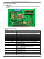
2.5 On the top sight, we have some connections and one EM78R5840 Romless chip
and some switches. The JP1 and the JP2 connect to the second layer of ICE for
the code instruction accessing. The JP3 is more important for ICE user. They are
the EM78R5840 control signals and I/O ports. ICE user can connect these
connections to user's application board. The connections are list in Table1.
2.6 The U1 is EM78R5840 Romless chip. The U2 is a 4K words ROM for on board
testing by piggyback. If user has developed application code by this ICE. User
can use PIGGYBACK (user can buy from ELAN) to connect to user's
application board with 4K word EPROM (27c128 ~ 27C512). To verify user's
program.
2.7 The D1 is a LED that indicates power is on or off.
2.8 Run WICE software to enter ICE environment.
2.9 User can use file “*.MIX” which generate by WICE for masking EPROM .
The *.mix file is a binary file and addressing from zero.
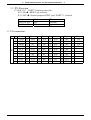
2.10 For different voltage system, user can select 5.0V or 3.6V.
The bottom layer of ICE (called GIC layer), JP1 selction:
Open : 3.6V
Short : 5.0V
Here
W 1-3
X