1
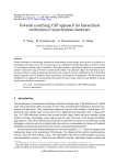
Overview
19
Overview
This tutorial demonstrates both basic and advanced PowerMill
simulations using the 4-bit adder shown in Figure 1.
CIN
A[0]
B[0]
CIN
AIN
SUM
ADDR
BIN
X4
COUT
S[0]
N3
A[1]
AIN
CIN
SUM
S[1]
ADDR
B[1]
BIN
COUT
X3
N2
A[2]
B[2]
A[3]
CIN
SUM
AIN
ADDR
BIN
COUT
S[2]
X2
N1
N1
CIN
SUM
AIN
MNDC
S[3]
ADDR
B[3]
BIN
COUT
X1
MPDC
COUT
Figure 1 Logic diagram of the four-bit adder circuit
This circuit contains 164 transistors and is simulated with 150
vectors. Figure 2 and Figure 3 further illustrate the adder
circuit used in this tutorial.
PowerMill User Guide