1
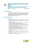
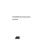
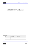
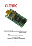
Universal ISP Socket User's guide
The UIS(Universal ISP Socket) was designed to complete the last
mile of the off-board ISP programming where the software can be
downloaded freely and the hardware can be purchased at a
reasonable low price, but the hobbyist/engineer still need to add
the power supply, wiring the socket and put on some extra
components to complete his work. Although it is simple, but it’s
annoying.
Now everything can be done without iron and solder.
PDF created with pdfFactory Pro trial version www.pdffactory.com
Features:
● USB powered voltage supply:
1. A 3.3V or 5V Target-VCC(TVCC) which can be controlled
manually or through a user-selectable high- or low-active
signal. It can also be disconnected from the Target socket
as required.
2. A 1.8V auxiliary LDO voltage regulator which was controlled
by same way as the TVCC has.
3. A 12V auxiliary switching voltage regulator which can be
controlled through another user-selectable high- or
low-active signal.
● A 4MHz oscillator which was controlled by the TVCC.
PDF created with pdfFactory Pro trial version www.pdffactory.com
● A COM port interface which supply logic signals of RD, TD, DTR,
RTS and CTS, inverted or non-inverted, at the TVCC voltage
level.
● A socketed 8-pin MicroController(ATTiny12) which can be
programmed to support specific programming requirements.
● An Open-drain pull-up inverter which can be used to handle the
bi-directional I/O pin of the target chip for its programming
requirement.
PDF created with pdfFactory Pro trial version www.pdffactory.com
Usage of the 4-pin terminal strip TPxx:
Each TPxx terminal strip has the following layout:
Each PINxx can be connected to a signal through a jumper wire:
Each PINxx can be set to TVCC or GND by a SHUNT jumper-socket:
Each PINxx can be pull-up by a resistor-modified 2-pin socket strip:
Each PINxx can have a capacitor-modified 2-pin socket strip to ground:
Each PINxx can be formed to a R-C oscillator:
A crystal oscillator circuit can be formed between two adjacent PINxx:
PDF created with pdfFactory Pro trial version www.pdffactory.com
Check List of the jumper setting:
1. Is the target IC powered from the on-board USB port?
No matter what the answer is, the VDD has to be set through JP101 to 5V(1,2
short) or 3.3V(2,3 short) for the supporting circuits to work.
YES: Short the JP102(ToTVCC) to connect VDD to the target TVCC node.
NO: JP102 open.
2. Is the target power controlled manually? or by a control signal?
The green LED1 will light when TVCC was applied. If 1.8V is required
by the target chip too, wire J1 to the proper socket pin PINxx.
Manual: Leave J7, J8 unconnected.
Use S1(ON) and S2(OFF) to manually control the TVCC and 1.8V.
Auto: 1. Press S2(OFF) to manually turn off the TVCC.
2. Wire the control signal to J7(CTLTVCC, high-active) or
J8(/CTLTVCC, low-active) as required.
PDF created with pdfFactory Pro trial version www.pdffactory.com
3. Does the programming require a 12V power?
The red LED2 will light when 12V was generated. The 12V power can only
be controlled by a signal.
YES: 1. Wire the control signal to J5(CTL12V, high-active) or
J6(/CTL12V, low-active).
2. Wire J3(12V) to the proper socket pin PINxx.
NO: Leave both J5 and J6 unconnected to disable the 12V generator.
4. Does the target chip require an external clock?
YES: 1. Short JP103(En4MHz) so the 4MHz OSC will be powered when the
TVCC was applied.
2. Wire J4(4MhZ) to the proper socket pin PINxx.
NO: Leave JP103 open to disable the oscillator.
PDF created with pdfFactory Pro trial version www.pdffactory.com
5. Does the programming signals come from the COM port?
Wire signals of J9(inverted) or J10(non-inverted) to the proper socket
pin PINxx.
When there is a bi-directional pin need to be handled (such as SDA of
the AT24C02), Two wirings were required. One is for the output path, from
this pin(TPxx-2) to an input node(such as the CTS). The other is for the
input path, from J12(open-drain with 2.2K pull-up) to this pin(TPxx-3).
Connect the J11 to its drive source.
Take the invert effect into consideration when using this inverter.
What the MicroController U6(ATTiny12) is for?
Dedicated function can be built to support the programming. For example,
the default function(factory shipping) is to supply the three /RESET pulses
required to force the P89LPC92x to enter its internal ISP routine, regardless
of its Boot_Status_Bit erased(cleared to 0) or not.
This procedure was triggered by a high-to-low transition on its
pin5(PB0). After the trigger, it will pull low the pin7(PB2) to enable the
VCC supply and wait for 20mS to steady, then sent out three /RESET pulses
from pin6(PB1).
The following wiring was required to complete its work under the "Flash
Magic" program with option "Assert DTR and RTS while COM port open" checked.
This option will activate(low) the RTS signal every time before it starts
the programming procedure and will stay low until finished.
/RTS J9-7(or -8) ----> P1-1(PB0)
/CTLVCC J8-1(or -2) <---- P1-3(PB2)
CPU's /RESET pin PINxx <---- P1-2(PB1)
;trigger input
;TVCC enable output
;/RESET pulse output
PDF created with pdfFactory Pro trial version www.pdffactory.com
One UIS-D48 package includes:
1.
2.
3.
4.
Colored signal jumper wires x10.
2pin socket strip x5
Shunt jumper socket x15
Signal jumper wire-pair x1
and there is Optional accessory(purchased separately):
PDF created with pdfFactory Pro trial version www.pdffactory.com
Wiring Examples:
ATMEL 24C02 DIP8(pin4 locate at TP24)
Using "PonyProg 2000" through COM port, select "SI ProgAPI" interface:
1. JP101-2,-3 short(set VDD to 3.3V)
2. Set TP21,TP22,TP23,TP24,TP27 to GND(short each TPxx-1,-2). Set TP28
to TVCC(short TP28-3,-4).
3. TP25-2(SDA) <--- J12(open drain, DTR). J11 <--- J9-5(/DTR).
4. TP25-3(SDA) ---> J10-9(CTS).
5. TP26-3(SCL) <--- J10-7(RTS).
6. Short JP102 to make the TVCC powered from VDD. TVCC was controlled
manually.
PDF created with pdfFactory Pro trial version www.pdffactory.com
P89LPC921 DIP20(pin10 locate at TP24)
Using "FlashMagic" through COM port:
1. JP101-2,-3 short(set VDD to 3.3V).
2. Set TP19 to GND(short TP19-1,-2). Set TP29 to TVCC(short TP29-3,-4).
3. J9-1(/RD) <--- TP26-3, the CPU-12(TxD). J10-1(RD) <--- TP1-1(GND) to pull-up the J9-1(/RD).
4. J9-3(/TD) ---> TP25-3, the CPU-11(RxD).
5. J9-7(/RTS) ---> P1-1(U6-PB0).
6. P1-2(U6-PB1) ---> TP18-3, the CPU-4(/RST).
7. P1-3(U6-PB2) ---> J8-1(/CTLTVCC).
8. Short JP102 to make the TVCC powered from VDD. TVCC was controlled by the "FlashMagic".
PDF created with pdfFactory Pro trial version www.pdffactory.com
MicroChip P16F84A DIP18(pin9 locate at TP24)
Using "PonyProg 2000" through COM port, select "SI ProgAPI" interface:
1.
2.
3.
4.
5.
6.
7.
JP101-1,-2 short(set VDD to 5V)
Set TP20 to GND(short TP20-1,-2). set TP29 to TVCC(short TP29-3,-4).
TP19-3(MCLR) <--- J3(12V). J5(CTL12V) <--- J10-3(TD).
TP27-3(RB6) <--- J10-7(RTS).
TP28-2(RB7) ---> J10-9(CTS).
TP28-3(RB7) <--- J12(open drain, DTR invert). J11 <--- J10-5(DTR).
Short JP102 to make the TVCC powered from VDD. TVCC was controlled
manually.
PDF created with pdfFactory Pro trial version www.pdffactory.com
Atmel AT91SAM7S64 on UIS-TQFP64 socket board
Using "Keil uVision3" and "ULink" JTAG debugger:
1. JP101-2,-3 short(set VDD to 3.3V)
2. Power the UIS-TQFP64 socket board by plug the 5x2 connector into
the UIS-D48 main board.
--Set the CPU power pins:
3. Set the following pins to GND(short TPxx-1,-2):
TP44(PGMEN2), TP2,TP17,TP46,TP60(GND).
4. Set the following pins to TVCC(short TPxx-3,-4):
TP40(TST), TP47(PGMEN1), TP48(PGMEN0), TP18,TP45,TP58(VDDIO),
TP59(VDDFLASH), TP7(VDDIN).
5. Bypass the 1.8V on-chip supply by insert a 2.2uF-modified
2pin socket strip into TP8-2(VDDOUT) and TP8-1(GND).
6. Wiring all 1.8V pins together:
TP8-3(VDDOUT) ---> TP12-2(VDDCORE). TP12-3 ---> TP24-2.
TP24-3 ---> TP54-2. TP54-3(VDDCORE) ---> TP64-2(VDDPLL).
--Wiring the on-board 4MHz clock to CPU:
7. Short JP103 to make the 4MHz OSC be enabled by the TVCC.
8. J4-1(4MHz) ---> TP62-2(XIN). J4-2(GND) ---> TP62-1(GND).
--Connect the ULink's JTAG signal to CPU:
9. ULink-5(TDI) <--- TP33-2(TDI). ULink-6(GND) ---> TP33-1(GND).
10. ULink-7(TMS) ---> TP51-2(TMS).
11. ULink-9(TCK) ---> TP53-2(TCK).
12. ULink-13(TDO) ---> TP49-2(TDO).
13. Short JP102 to make the TVCC powered from VDD. TVCC was controlled
manually.
PDF created with pdfFactory Pro trial version www.pdffactory.com
Reference sites for download free programming software:
PonyProg --supporting 24xx, 93xx, PIC, AVR and many other serial devices.
http://www.lancos.com/prog.html
Flash Magic --dedicated for supporting the NXP devices.
http://www.flashmagictool.com/
AVRDUDE --dedicated for supporting the AVR series.
http://www.bsdhome.com/avrdude/
PDF created with pdfFactory Pro trial version www.pdffactory.com