1
VERTEX ANTENNENTECHNIK GMBH
Doc.No.
Version:
OM1002114-21320
1.3
lower universal joints (variable “fix”)
upper universal joints (variable “mov”)
Jack
x [mm]
y [mm]
z [mm]
x [mm]
y [mm]
z [mm]
4
-1823.6568
-320.3860
0.0
R1*cos(159°)
R1*sin(159°)
4620.0
5
-1191.2478
-1416.5320
0.0
R1*cos(261°)
R1*sin(261°)
4620.0
6
1190.9897
-1417.3090
0.0
R1*cos(279°)
R1*sin(279°)
4620.0
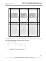
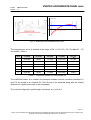
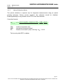
Table 2: Actual coordinates of the jackscrew points with R1=1550.0
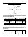
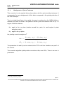
The mount installation on Mauna Loa differs from this symmetrical coordinates; the Az = 0
axes of the telescope as shown in Fig. 1 does not point exactly to North but is rotated by
several degrees.
This Azimuth offset is must be entered at ACU, HPC and PTC as a parameter.
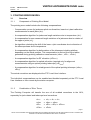
The following relationship applies:
Azsky = Azmount + OffsetAz
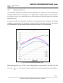
Internally, the coordinate transformations inside the three servo computer continue to use
the telescope coordinate system. Commands from user or superior computer was well as
position displays show the azimuth related to the “world coordinates”. The position
commands are converted accordingly before being entered into the hexapod coordinate
transformation:
Azmount,cmd = Azsky,cmd - OffsetAz
From this point of view, all azimuth angles contained in definitions and formulae earlier in
this paragraph are mount related azimuth angles.
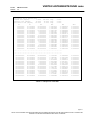
The [mount related] coordinates of upper and lower u-joints are stored in an ASCII file on
the CF memory cards of ACU, PTC and HPC.
The coordinate files of all three computers must be identical at all times!
WARNING
Any significant change in coordinates, any typos or swapped digits may
lead to severe damage of the telescope because collision situations could
occur without being detected by software or hardware. Utmost caution is
needed when modifications to the geometry file(s) are required. Such
changes should only be modified by well trained and experienced staff.
The manufacturer cannot be held responsible for malfunctions and/or any
damage resulting from modification of the geometry file(s).
page 5
NOTE: THIS DOCUMENT CONTAINS PROPRIETARY INFORMATION AND MAY NOT BE DISCLOSED WITHOUT THE WRITTEN
CONSENT OF VERTEX ANTENNENTECHNIK GmbH, DUISBURG