1
VERTEX ANTENNENTECHNIK GMBH
Doc.No.
Version:
OM1002114-21320
1.3
3. POINTING ERROR MODEL
3.1
Overview
3.1.1
Components of Pointing Error Model
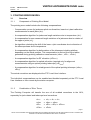
The pointing error model includes the following compensations:
- Compensation curves for jackscrew pitch non-linearities, based on i-plant calibration
measurements for each jacks (∆Lp).
- A compensation algorithm for jackscrew length variations due to temperature (∆Lt).
- A compensation for non-measured length variations of a jackscrew due to rotation of
the upper u-joints (∆Lr).
- An algorithm calculating the shift of the lower u-joint coordinates due to distortion of
the telescope base due to temperature.
- A compensation algorithm for deformations of the telescope including platform
depending on the actual position. This compensation is derived from error tables
generated during pointing calibration measurements (∆Azerr , ∆Elerr , ∆Polerr).
- A compensation algorithm for RF refraction (∆Elrefract)
- A compensation algorithm for optical refraction (required only for alignment
measurements using an optical pointing telescope) (∆Elrefract).
- A compensation algorithm for misalignment of the optical pointing telescope (∆Azopt ,
∆Elopt)
The actual corrections are displayed at the PTC Local User Interface.
The individual compensations can be enabled and disabled separately at the PTC Local
User Interface or from remote by the station computer.
3.1.2
Combination of Error Terms
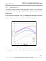
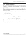
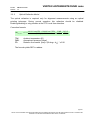
The Pointing Computer will transfer the sum of all enabled corrections to the ACU,
separately for jack related and telescope level corrections.
∆Ltot,i
∆Aztot
∆Eltot
∆Poltot
=
=
=
=
∆Lp,i + ∆Lt,i + ∆Lr,i
∆Azerr + ∆Azopt
∆Elerr + ∆Elopt + ∆Elrefract
∆Polerr
page 6
NOTE: THIS DOCUMENT CONTAINS PROPRIETARY INFORMATION AND MAY NOT BE DISCLOSED WITHOUT THE WRITTEN
CONSENT OF VERTEX ANTENNENTECHNIK GmbH, DUISBURG