1
English
ST-EP4
User’s Manual
M00043000EN
TM-T88VST-EP4 User’s Manual 1
English
Standards and Approvals
The following standards are applied only to the printers that are so labeled. (EMC is tested using the EPSON
power supplies.)
Europe:
CE marking
North America:
FCC/ICES-003 Class A
Oceania:
AS/NZS CISPR22 Class A
WARNING
This is a Class A product. In a domestic environment this product may cause radio interference in which
case the user may be required to take adequate measures.
The connection of a non-shielded printer interface cable to this printer will invalidate the EMC standards
of this device. You are cautioned that changes or modifications not expressly approved by PioneerPOS
Inc. could void your authority to operate the equipment.
CE Marking
The printer conforms to the following Directives and Norms:
Directive 2004/108/EC EN 55022 Class A
EN 55024
IEC 61000-4-2
IEC 61000-4-5
IEC 61000-4-3
IEC 61000-4-6
IEC 61000-4-4
IEC 61000-4-11
FCC Compliance Statement For American Users
This equipment has been tested and found to comply with the limits for a Class A digital device, pursuant
to Part 15 of the FCC Rules. These limits are designed to provide reasonable protection against harmful
interference when the equipment is operated in a commercial environment.
This equipment generates, uses, and can radiate radio frequency energy and, if not installed and used in
accordance with the instruction manual, may cause harmful interference to radio communications.
Operation of this equipment in a residential area is likely to cause harmful interference, in which case the
user will be required to correct the interference at his own expense.
For Canadian Users
This Class A digital apparatus complies with Canadian ICES-003.
À l’intention des utilisateurs canadiens
Cet appareil numérique de classe A est conforme à la norme canadienne NMB-003.
2 ST-EP4 User’s Manual
English
Important Safety Information
This section presents important information intended to ensure safe and effective
use of this product. Read this section carefully and store it in an accessible
location.
Key to Symbols
The symbols in this manual are identified by their level of importance, as defined
below. Read the following carefully before handling the product.
WARNING:
Warnings must be followed carefully to avoid serious bodily injury.
CAUTION:
Cautions must be observed to avoid minor injury to yourself, damage to your
equipment, or loss of data.
Note:
Notes have important information and useful tips on the operation of your equipment.
Safety Precautions
WARNING:
Shut down your equipment immediately if it produces smoke, a strange odor, or
unusual noise. Continued use may lead to fire or shock. Immediately unplug the
equipment and contact your dealer for advice.
Never attempt to repair this product yourself. Improper repair work can be
dangerous.
Never disassemble or modify this product. Tampering with this product may
result in injury, fire, or shock.
Be sure to use the specified power source. Connection to an improper power
source may cause fire.
Do not allow foreign matter to fall into the equipment. Penetration by foreign
objects may lead to fire.
If water or other liquid spills into this equipment, unplug the power cord
immediately, and then contact your dealer for advice. Continued usage may
lead to fire.
Do not use aerosol sprayers containing flammable gas inside or around this
product. Doing so may cause fire.
CAUTION:
Do not connect cables in ways other than those mentioned in this manual.
Different connections may cause equipment damage and burning.
Be sure to set this equipment on a firm, stable, horizontal surface. The product
may break or cause injury if it falls.
Do not use in locations subject to high humidity or dust levels. Excessive humidity
and dust may cause equipment damage or fire.
Do not place heavy objects on top of this product. Never stand or lean on this
product. Equipment may fall or collapse, causing breakage and possible injury.
ST-EP4 User’s Manual 3
English
Take care not to injure your fingers on the manual cutter
•
When you remove printed paper
•
When you perform other operations such as loading/replacing roll
paper
To ensure safety, unplug this product before leaving it unused for an extended
period.
Do not connect a telephone line to the drawer kick-out connector; otherwise
the printer and the telephone line may be damaged.
Caution Labels
The caution label on the product indicates the following precaution.
CAUTION:
Do not touch the thermal head because it can be very hot after printing.
Restriction of Use
When this product is used for applications requiring high reliability/safety, such
as transportation devices related to aviation, rail, marine, automotive, etc.;
disaster prevention devices; various safety devices, etc.; or functional/precision
devices, etc.; you should use this product only after giving consideration to
including fail-safes and redundancies into your design to maintain safety and
total system reliability. Because this product was not intended for use in
applications requiring extremely high reliability/safety, such as aerospace
equipment, main communication equipment, nuclear power control equipment,
or medical equipment related to direct medical care, etc., please make your own
judgment on this product’s suitability after a full evaluation.
4 ST-EP4 User’s Manual
English
Setting Up the Printer
To set up the printer, follow the steps below.
1. Unpacking (See “Unpacking” on page 5.)
2. Connecting the cables (See “Connecting the Cables” on page 7.)
3. Installing the printer (See “Installing the Printer” on page 9.)
4. Setting the paper width (See “Setting the Paper Width” on page 12.)
5. Installing the roll paper (See “Installing Roll Paper” on page 13.)
6. Operation check with test print (See “Test Printing” on page 14.)
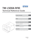
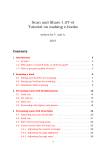
Unpacking
The following items are included with the standard specification printer.
If any item is damaged, contact your dealer.
Setup Guide
Wall hanging
bracket
Printer
Control panel label for
wall-hanging installation
58-mm width
paper guide plate
Roll paper
(for operation check)
AC adapter
ST-EP4 User’s Manual 5
English
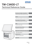
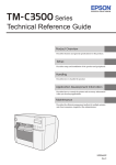
Part Names
Roll paper cover
Control panel
Manual cutter
Cutter cover
Cover open lever
Power switch
Control Panel
Power LED
This LED is on when the printer is on.
Error LED
This indicates an error.
Paper LED
On indicates a paper out. Flashing indicates standby.
Feed button
This button feeds paper.
6 ST-EP4 User’s Manual
English
Connecting the Cables
CAUTION:
For using a serial interface, use a null modem cable.
For using a parallel interface, use an IEEE 1284 cable.
For using a USB interface, do not turn on the printer before installing the printer
driver.
For using an Ethernet (10Base-T/100Base-TX) interface, do not connect a
telephone line or a drawer kick-out cable to the Ethernet connector.
When LAN cables are installed outdoors, make sure devices without proper
surge protection are cushioned by being connected through devices that do
have surge protection. Otherwise, the devices can be damaged by lightning.
1.
2.
Make sure the printer is turned off.
Connect the interface cable to the printer.
For the shape of each connector, see the illustration below. (Mounted
interfaces vary by the printer model.)
IEEE1284
RS-232
DK
㩷
10BASE-T/
100BASE-TX
DC24V
(Drawer kick-out
connector)
USB
Note:
When connecting the USB cable, fix the USB cable with the hook shown in the illustration
below to prevent the cable from coming off.
Hook
3.
4.
Connect the other end of the interface cable to the computer.
Connect the AC cable to the AC adapter.
ST-EP4 User’s Manual 7
English
5.
Connect the DC cable of the AC adapter to the power connector of the printer.
6.
Insert the AC plug into a socket.
About Drawer Kick-out Connection
For the drawer side, use a connector with 6-position 6-contact (RJ12 telephone
jack).
CAUTION:
Do not connect a telephone line to the drawer kick-out connector; otherwise
the printer and the telephone line may be damaged.
Use a shield cable for the drawer connector cable.
Drawer kick-out drive signal
Output signal:
Output voltage
Output current
Approximately 24 V
1 A or less
CAUTION:
To avoid an overcurrent, the resistance of the drawer kick-out solenoid must be
24 or more.
Connector Pin Assignments
#1
#6
Pin number
8 ST-EP4 User’s Manual
Signal
Direction
1
Frame GND
—
2
Drawer kick-out drive signal 1
Output
3
Drawer open/close signal
Input
4
+ 24 V
—
5
Drawer kick-out drive signal 2
Output
6
Signal GND
—
English
Installing the Printer
You can install the printer horizontally on a flat surface (with the paper exit on
top) or hang it on a wall using the included wall hanging bracket.
CAUTION:
When installing the printer horizontally, take measures to prevent the printer
from moving by vibration during paper cutting and when using a drawer.
Horizontal installation
Wall-hanging installation
To hang the printer on the wall, follow the steps below.
CAUTION:
To fix the printer securely, install the wall hanging bracket on a wall made of
wood, concrete, or metal. The thickness of the wall should be 10 mm {0.4”} or
more.
Be sure to use metallic screws.
The screws on the wall side must have a pull-out strength of 150 N (15.3 kgf) or
more.
1.
Attach the included control panel label for wall-hanging installation to the
position of the control panel.
Control panel label for
wall-hanging installation
ST-EP4 User’s Manual 9
English
2.
Install 2 screws (screw diameter: 4 mm {0.16"}, head diameter: 7 to 9 mm {0.28
to 0.35"}) in the wall at an interval of 80 mm {3.15"}. Make sure the length of
the screw’s body in the wall is 10 mm {0.39"} or more, and the length outside
the wall is 3 to 4 mm {0.12 to 0.16"}.
3~ 4 mm
7~ 9 mm
80 mm
4 mm
10 mm or more
3.
4.
Remove the installed 2 screws from the printer, as shown in the illustration
below.
Install the wall hanging bracket on the printer, and fix it using the screws
removed in Step 2.
Screws
Wall hanging
bracket
10 ST-EP4 User’s Manual
English
5.
Align the holes in the wall hanging bracket with the screws on the wall, and
hook it securely.
ST-EP4 User’s Manual 11
English
Setting the Paper Width
You can change the paper width from 80 to 58 mm by installing the included
58-mm width paper guide plate. Follow the steps below to change the paper
width.
CAUTION:
Once you change the paper width from 80 to 58 mm, you cannot change it
back to 80 mm.
When changing the paper width, be sure to make the setting for the paper
width with memory switches. (See “Memory Switch Setting Mode” on page 15.)
1.
Use the cover open lever to open the roll paper cover.
2.
Align 3 projections on the 58-mm width paper guide plate with the
rectangular holes in the printer, and push it downwards.
58-mm width
paper guide plate
Rectangular holes
3.
4.
Install the roll paper. (See “Installing Roll Paper” on page 13.)
Close the roll paper cover.
12 ST-EP4 User’s Manual
English
Installing Roll Paper
Follow the steps below to install the roll paper.
1. Use the cover open lever to open the roll paper cover.
Cover open lever
2.
Remove the used roll paper core if any, and insert the roll paper. The correct
direction of the paper is shown in the illustration below.
ST-EP4 User’s Manual 13
English
3.
Pull out some paper, and close the roll paper cover.
2
1
4.
Tear off the paper.
Test Printing
After the printer setup or when the printer is not operating correctly, you can
check the printer operation with test printing. If the printer performs pattern
printing following the steps below, the printer is operating normally.
1. Make sure the paper is correctly inserted and all the covers are closed.
2. While pressing the Feed button, turn on the printer.
3. After the printer prints its status and the Paper LED flashes, press the Feed
button again to restart the test printing.
The test printing is completed when "*** completed***” is printed.
14 ST-EP4 User’s Manual
English
Setting Memory Switch
The following memory switch settings are available in the memory switch setting
mode.
❏ Print density
❏ Printing speed
❏ Communication conditions using a serial interface
❏ Roll paper width
❏ Defaut value of Character code page/International character set
❏ Selection of an interface
❏ Power supply capacity
❏ Interface setting
❏ Communication conditions using a USB interface
❏ Near-end sensor setting
❏ Built-in buzzer function/Autocutting command sound interval
Memory Switch Setting Mode
Follow the steps below to start the memory switch setting mode.
1. Make sure the paper is correctly inserted and all the covers are closed.
2. While pressing the Feed button, turn on the printer.
3. After the printer prints its status and the Paper LED flashes, keep pressing
the Feed button until the printer starts printing.
4. After the printer prints operating instructions, press the Feed button three
times.
5. Keep pressing the Feed button again until the printer starts printing.
6. After the printer prints setting instructions, make settings by following them.
Note:
After one setting has been completed, the printer stores the setting and then starts
initializing. After that, the printer returns to the normal mode.
ST-EP4 User’s Manual 15
English
Cleaning
Cleaning the Printer Case
Be sure to turn off the printer, and wipe the dirt off the printer case with a dry
cloth or a damp cloth.
CAUTION:
Never clean the product with alcohol, benzine, thinner, or other such solvents.
Doing so may damage or break the parts made of plastic and rubber.
Cleaning the Thermal Head
CAUTION:
After printing, the thermal head can be very hot. Be careful not to touch it and
to let it cool before you clean it.
Do not damage the thermal head by touching it with your fingers or any hard
object.
Turn off the printer, open the roll paper cover, and clean the thermal elements of
the thermal head with a cotton swab moistened with an alcohol solvent (ethanol
or IPA).
It is recommended to clean the thermal head periodically (generally every
3 months) to maintain receipt print quality.
Thermal head
16 ST-EP4 User’s Manual
English
Troubleshooting
No lights on the control panel
Check whether the power supply cable is correctly connected to the printer and
the socket.
Error LED on with no printing
❏
❏
Check whether the roll paper cover is closed. If it is open, close it.
If the Paper LED is on, check whether the roll paper is correctly installed and
any roll paper remains.
Error LED flashing with no printing
❏
❏
❏
Check whether a paper jam has occurred. If paper is jammed, remove the
jammed paper referring to the description below and install the roll paper
correctly.
Printing stops if the head overheats and resumes automatically when it cools.
For other cases, turn the printer off, and after 10 seconds, back on.
When a paper jam occurs
When a paper jam occurs, never pull out the paper forcibly. Open the roll paper
cover and remove the jammed paper.
CAUTION:
Do not touch the thermal head, because it can be very hot after printing.
If the roll paper cover does not open, follow the steps below.
1. Turn off the printer.
2. Put the fingers in the indents in both sides of the cutter cover, and slide it
toward the arrow in the illustration below to remove it.
Cutter cover
Indent
ST-EP4 User’s Manual 17
English
3.
Turn the knob until you see a triangle in the opening. This returns the cutter
blade to the normal position. See the operating instructions on the back of the
cutter cover.
Triangle
4.
5.
Knob
Install the cutter cover.
Open the roll paper cover and remove the jammed paper.
18 ST-EP4 User’s Manual
English
List of Commands
Command
Function
HT
Horizontal tab
LF
Print and line feed
FF
Print and return to standard mode (in page mode)
CR
Print and carriage return
CAN
Cancel print data in page mode
DLE EOT
Transmit real-time status
DLE ENQ
Send real-time request to printer
DLE DC4
Generate pulse in real-time (fn = 1)
Execute power-off sequence (fn = 2)
Clear buffer(s) (fn = 8)
ESC FF
Print data in page mode
ESC SP
Set right-side character spacing
ESC !
Select print mode(s)
ESC $
Set absolute print position
ESC %
Select/cancel downloaded character set
ESC &
Define downloaded characters
ESC *
Select bit-image mode
ESC -
Turn underline mode on/off
ESC 2
Select default line spacing
ESC 3
Set line spacing
ESC =
Select peripheral device
ESC ?
Cancel downloaded characters
ESC @
Initialize printer
ESC D
Set horizontal tab positions
ESC E
Turn emphasized mode on/off
ESC G
Turn double-strike mode on/off
ESC J
Print and feed paper
ESC L
Select page mode
ESC M
Select character font
ESC R
Select an international character set
ESC S
Select standard mode
ESC T
Select print direction in page mode
ESC V
Turn 90° clockwise rotation mode on/off
ESC W
Set print area in page mode
ESC \
Set relative print position
ESC a
Select justification
ESC c 3
Select paper sensor(s) to output paper-end signals
ESC c 4
Select paper sensor(s) to stop printing
ESC c 5
Enable/disable panel buttons
ESC d
Print and feed n lines
ESC i
Partial cut (one point left uncut)
ESC m
Partial cut (three points left uncut)
ESC p
Generate pulse
ESC t
Select character code table
ST-EP4 User’s Manual 19
English
Command
Function
ESC u
Transmit peripheral device status
ESC v
Transmit paper sensor status
ESC {
Turn upside-down print mode on/off
FS g 1
Write to NV user memory
FS g 2
Read from NV user memory
FS p
Print NV bit-image
FS q
Define NV bit image
GS !
Select character size
GS $
Set absolute vertical print position in page mode
GS ( A
Execute test print
GS ( D
Enable/disable real-time command
GS ( E
Set user setup commands
<Function 1> Change into the user setting mode
<Function 2> End the user setting mode session
<Function 3> Set the memory switch setting values
<Function 4> Transmit the memory switch setting values
<Function 5> Set the customized values
<Function 6> Transmit the customized values
<Function 11> Set conditions for serial interface communication
<Function 12> Transmit conditions for serial interface communication
GS ( H
Request transmission of response or status
<Function 48> Set the process ID response.
GS ( K
Select print control method(s)
<Function 50> Select the print speed.
<Function 97> Select the number of parts for the thermal head energizing.
GS ( L / GS 8 L
Set graphics data
<Function 48> Transmit the NV graphics memory capacity.
<Function 50> Print the graphics data in the print buffer.
<Function 51> Transmit the remaining capacity of the NV graphics memory.
<Function 64> Transmit the key code list for defined NV graphics.
<Function 65> Delete all NV graphics data.
<Function 66> Delete the specified NV graphics data.
<Function 67> Define the NV graphics data (raster format).
<Function 69> Print the specified NV graphics data.
<Function 112> Store the graphics data in the print buffer (raster format).
GS ( k
Set up and print symbol
<Function 065> PDF417: Set the number of columns in the data region.
<Function 066> PDF417: Set the number of rows.
<Function 067> PDF417: Set the width of the module.
<Function 068> PDF417: Set the row height.
<Function 069> PDF417: Set the error correction level.
<Function 070> PDF417: Select the options.
<Function 080> PDF417: Store the data in the symbol storage area.
<Function 081> PDF417: Print the symbol data in the symbol storage area.
<Function 082> PDF417: Transmit the size information of the symbol data in the
symbol storage area.
<Function 165> QR Code: Select the model.
<Function 167> QR Code: Set the size of module.
<Function 169> QR Code: Select the error correction level.
<Function 180> QR Code: Store the data in the symbol storage area.
<Function 181> QR Code: Print the symbol data in the symbol storage area.
<Function 182> QR Code: Transmit the size information of the symbol data in
the symbol storage area.
GS *
Define downloaded bit-image
GS /
Print downloaded bit-image
20 ST-EP4 User’s Manual
English
Command
Function
GS :
Start/end macro definition
GS B
Turn white/black reverse print mode on/off
GS H
Select print position of HRI characters
GS I
Transmit printer ID
GS L
Set left margin
GS P
Set horizontal and vertical motion units
GS V
Select cut mode and cut paper
GS W
Set print area width
GS \
Set relative vertical print position in page mode
GS ^
Execute macro
GS a
Enable/disable Automatic Status Back (ASB)
GS b
Turn smoothing mode on/off
GS f
Select font for HRI characters
GS g 0
Initialize maintenance counter
GS g 2
Transmit maintenance counter
GS h
Set barcode height
GS k
Print barcode
GS r
Transmit status
GS v 0
Print raster bit-image
GS w
Set barcode width
List of Multi-byte Code Characters Commands
For Japanese/Simplified Chinese/Traditional Chinese font models, the following
commands are available.
Command
FS !
Function
Select print mode(s) for Kanji characters
FS &
Select Kanji character mode
FS -
Turn underline mode on/off for Kanji characters
FS .
Cancel Kanji character mode
FS 2
Define user-defined Kanji characters
FS C
Select Kanji character code system
FS S
Set Kanji character spacing
FS W
Turn quadruple-size mode on/off for Kanji characters
ST-EP4 User’s Manual 21
English
ST-EP4 Specifications
58 mm paper width*1
80 mm paper width
Printing method
Thermal line printing
Dot density
180 dpi × 180 dpi [dots per 25.4 mm {1"}]
Printing width
72.2 mm {2.84"}, 512 dot positions 50.8 mm {2.00"}, 360 dot positions
Characters per line
Font A: 42; Font B: 56; Kanji: 21
Printing speed
200 mm/s {7.87"/s} max.; 47 lps (4.23 mm {0.17"} feed)
Ladder bar code: 100 mm/s {2.4"/s}
Font A: 30; Font B: 40; Kanji: 15
The above speed values are approximate.
The values are when the printer prints with density “Normal” at 25°C {77°F}.
Speed is adjusted automatically depending on the voltage applied and
head temperature.
Roll paper
(single-ply)
Width
79.5 mm ± 0.5 mm {3.13" ± 0.02"}
57.5 mm ± 0.5 mm {2.26" ± 0.02"}
Diameter Maximum outside diameter: 83 mm {3.27"}
Spool
Spool diameter: Inside: 12 mm {0.47"}; Outside: 18 mm {0.71"}
Interface
Serial (RS-232)/Parallel (IEEE1284)/Ethernet (10BASE-T/100BASE-TX)/
USB [Compliance: USB 2.0, Communication speed: Full-speed
(12 Mbps)]
Supply voltage*2
DC + 24 V ± 7%
Current consumption
Mean: Approx. 1.8A
Temperature
Operating:
Storage:
5 to 45°C {41 to 113°F}
–10 to 50°C {14 to 122°F}, except for paper
Humidity
Operating:
Storage:
10 to 90% RH
10 to 90% RH, except for paper
Overall dimensions
153 × 140 × 199 mm {6.02 × 5.51 × 7.83"} (H × W × D)
Weight (mass)
Approx. 1.7 kg {3.74 lb}
dpi: dots per 25.4 mm (dots per inch), Mbps: megabits per second
*1: The values are those when the paper width is changed to 58 mm by installing the 58-mm width
paper guide plate and making the paper width setting with the memory switch.
For how to install the 58-mm width paper guide plate, see “Setting the Paper Width” on page 12.
*2: Be sure to use a safety-standards-applied power source that meets the following specifications.
Rated output: 24 V/2.0 A or more, Maximum output: 240 VA or less
22 ST-EP4 User’s Manual