1
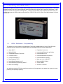
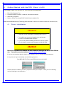
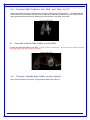
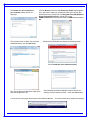
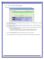
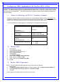
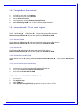
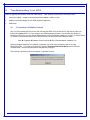
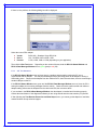
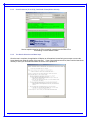
Dearborn Protocol Adapter 4 Plus (DPA 4 Plus) Installation and User Manual Driver Version: Firmware Version DPA 4 Plus: Firmware Version DPA 4: Firmware Version DPA RF: Firmware Version DPA III Plus (HW 5.00): Native Drivers Version: Document Revision Document Date: 4.4 April 8, 2010 5.55 60.011 37.149 37.149 63.011 10.01 DPA 4 Plus Installation and User Manual Permission is granted to copy any or all portions of this manual, provided that such copies are for use with the DPA product and that “© 2010 Dearborn Group Technology”, (herein referred to as “Dearborn Group”, or “DG”), remains on all copies. The accompanying software, provided for use with the DPA 4 Plus, is also copyrighted. software for back-up purposes only. Permission is granted to copy this IMPORTANT To ensure your success with this product, it is essential that you read this document carefully before using the hardware. Damage caused by misuse of the hardware is not covered under product warranty. When using this manual, please remember the following: This manual may be changed, in whole or in part, without notice. Dearborn Group Technology assumes no responsibility for any damage resulting from the use of this hardware and software. Specifications presented herein are provided for illustration purposes only and may not accurately represent the latest revisions of hardware, software or cabling. No license is granted, by implication or otherwise, for any patents or other rights of Dearborn Group Technology or of any third party. The “DG” square logo is a registered trademark of Dearborn Group Technology. in this manual are trademarks of their respective manufacturers. Other products that may be referenced The DPA Product line has been awarded the following U.S. Patents: Patent # 6,772,248 7,152,133 7,337,245 Page 2 of 28 Date 08-03-04 12-19-06 02-26-08 Patent Overview Protocol adapter for in-vehicle networks. Expanded functionality protocol adapter for in-vehicle networks. Protocol Adapter for Passing Diagnostic Messages between Vehicle Networks and a Host Computer. DPA 4 Plus Installation and User Manual Table of Contents Table of Contents ........................................................................................................................... 3 1. Safety First ............................................................................................................................. 4 2. Introducing the DPA 4 Plus .................................................................................................. 5 2.1. OEM Software Compatibility ........................................................................................... 5 2.2. Standards and Protocols Supported ............................................................................... 6 2.3. System Requirements .................................................................................................... 6 3. Windows Vista and Windows 7 Support Notes .................................................................. 7 3.1. UAC and the TMC RP1210 Standard ............................................................................. 7 3.2. UAC and the Dearborn Group Adapter Validation Tool (AVT) ....................................... 7 3.3. UAC and the DPA Options Program .............................................................................. 7 3.4. UAC Requirements for All DPA Utility Programs............................................................ 7 3.5. More Information on UAC ............................................................................................... 7 4. Getting Started with the DPA (Steps 1-4 of 6) .................................................................... 8 4.1. Driver Installation ............................................................................................................ 8 4.2. Connect USB Cable to the DPA and Then to PC ........................................................... 9 4.1. Connect Vehicle-Side Cable to the DPA ........................................................................ 9 4.2. Connect Vehicle-Side Cable to the Vehicle .................................................................... 9 5. Finalize PC Install (Step 5 of 6) .......................................................................................... 10 5.1. Step 5. Finalize PC Install (Windows 2000/XP)........................................................... 10 5.2. Step 5. Finalize PC Install (Vista and Windows 7) ...................................................... 11 6. Firmware Update (Step 6 of 6)............................................................................................ 13 6.1. Run the DPA Flash Updater ......................................................................................... 14 7. Configuring OEM Applications to Use the DPA 4 Plus ................................................... 15 7.1. Notes on Selecting an RP1210 Compliant Adapter...................................................... 15 7.2. Allison DOC .................................................................................................................. 15 7.3. Bendix ABS Diagnostics ............................................................................................... 15 7.4. Caterpillar Electronic Technician .................................................................................. 16 7.5. Cummins Insite ............................................................................................................. 16 7.6. Detroit Diesel Diagnostic Link V7 ................................................................................. 16 7.7. Eaton ServiceRanger 3.x .............................................................................................. 16 7.8. Freightliner ServiceLink ................................................................................................ 17 7.9. International Truck and Engine ..................................................................................... 17 7.10. Meritor-WABCO ABS Toolbox ...................................................................................... 17 7.11. Volvo/Mack VCADS Pro ............................................................................................... 18 7.12. Volvo/Mack Premium Tech Tool (PTT) ........................................................................ 18 8. Troubleshooting Your DPA ................................................................................................ 19 8.1. Connection-Related Issues........................................................................................... 19 8.2. Not Seeing DPA 4 Plus in OEM Application VDA Selection List .................................. 22 8.3. USB-Related Issues ..................................................................................................... 23 9. Modifying DPA Settings – DPA Options Program ........................................................... 24 9.1. J1939 FAST_TRANSPORT.......................................................................................... 24 10. Warranty Information and Limitation Statements ............................................................ 25 10.1. Warranty Information .................................................................................................... 25 10.2. Limitation Statements ................................................................................................... 25 11. Product Specifications........................................................................................................ 26 11.1. DPA 4 Plus Physical and Electrical .............................................................................. 26 11.2. DPA 4 Plus Pinouts ...................................................................................................... 26 12. Technical Support and Return Merchandise Authorization (RMA) ................................ 27 12.1. Technical Support ......................................................................................................... 27 12.2. Return Merchandise Authorization (RMA) .................................................................... 27 13. Appendix A – Software Developer/Integrator Notes ........................................................ 28 13.1. Bundling the DPA with Your OEM Installation – Silent Install ...................................... 28 13.2. Native Driver Device IDs Match RP1210 Device IDs ................................................... 28 Page 3 of 28 DPA 4 Plus Installation and User Manual 1. Safety First It is essential that the user read this document carefully before using the hardware. The DPA 4 Plus device is to be used by those trained in the troubleshooting and diagnostics of light-duty through heavyduty vehicles. The user is assumed to have a very good understanding of the electronic systems contained on the vehicles and the potential hazards related to working in a shop-floor environment. Dearborn Group Technology understands that there are numerous safety hazards that cannot be foreseen, so we recommend that the user read and follow all safety messages in this manual, on all of your shop equipment, from your vehicle manuals, as well as internal shop documents and operating procedures. Always block drive, steer, and trailer wheels both front and back when testing. Use extreme caution when working around electricity. When diagnosing any vehicle, there is the risk of electric shock both from battery-level voltage, vehicle voltages, and from building voltage. Do not smoke or allow sparks or open flames near any part of the vehicle fueling system or vehicle batteries. Always work in an adequately ventilated area, and route vehicle exhaust outdoors. Do not use this product in an environment where fuel, fuel vapor, exhaust fumes, or other potentially hazardous liquids, solids, or gas/vapors could collect and/or possibly ignite, such as in an unventilated area or other confined space, including below-ground areas. Page 4 of 28 DPA 4 Plus Installation and User Manual 2. Introducing the DPA 4 Plus The DPA 4 Plus product is used to connect vehicle communication networks and personal computers (PCs). This allows programs written for the PC to retrieve pertinent vehicle information such as fault codes, component information, as well as perform vehicle and component level diagnostics. Although the latest DPA product released is the DPA 4 Plus, this manual covers previous DPA models including the DPA 4, DPA RF, DPA III Plus, DPA III Plus /MH (Hardware 5.00) and the DPA RF. The DPA 4 Plus 2.1. OEM Software Compatibility The adapter you have purchased is provided with a Technology and Maintenance Council (TMC) RP1210Acompliant interface and has been validated against the following OEM and component applications: Allison DOC™ Freightliner ServiceLink Bendix® ACOM International® Diamond Logic Builder Caterpillar® Electronic Technician International® InTune Cummins® Insite™ International® Master Diagnostics Cummins PowerSpec™ International® ServiceMaxx Dana Diagnostic Tool™ Mack and Volvo VCADS/PTT Detroit Diesel Diagnostic Link™ Meritor-WABCO Toolbox Detroit Diesel Reprogramming Station™ Vansco VMMS Eaton ServiceRanger ZF-Meritor TransSoft Any application claiming RP1210A-compliance should work if the application and adapter both support the same protocol(s) and operating system(s). Page 5 of 28 DPA 4 Plus Installation and User Manual 2.2. Standards and Protocols Supported The adapter you have purchased provides more protocol and standards support than any other commercially available diagnostic adapter. 2.2.1. Operating Systems and Standards Supported Operating Systems o Windows 2000® o Windows XP® o Windows Vista® 32-bit and 64-bit Versions o Windows 7® 32-bit and 64-bit Versions TMC RP1210A CE Certification J1979 Vehicle Electronic Programming Station (VEPS) J2214/J2461 2.2.2. RP1210 Defined Protocols Supported J1939 CAN (ISO11898) CAN@500k/J2284/GMLAN o Supported under the IESCAN protocol name. J1708/J1587 J1850 GM (Class 2) 2.2.3. Additional Protocols Supported by Native Drivers J2411 (GM SWCAN) ALDL 2.3. System Requirements If you are not familiar with selecting a PC platform for your diagnostic applications, Dearborn Group Technology recommends starting with a computer that is compatible with the latest version of the TMC RP1208 (PC Selection Guidelines for Service Tool Applications). In addition to the aforementioned document, the following items are recommended or required. Item PC Processor RAM USB Port Operating System Page 6 of 28 Requirement IBM-Compatible 1GHz or Faster 256MB (512MB Preferred) USB Version 1.1 or Higher Windows 2000 Windows XP Windows Vista (32-bit or 64-bit) Windows 7 (32-bit or 64-bit) DPA 4 Plus Installation and User Manual 3. Windows Vista and Windows 7 Support Notes Microsoft® has made great strides in updating their operating systems to protect against malicious software. With Windows Vista, Microsoft introduced User Account Control (UAC). UAC strictly enforces the differences between an administrator and a standard user account. When an action that could potentially compromise the PC such as writing files to the C:\Windows directory or registry is requested, the user is prompted for an administrator name and password. If the user is already an administrator, they are still prompted to confirm the action. Generally speaking, whenever you see the icon on a button, you will need an administrator’s password to perform that operation. Microsoft security shield 3.1. UAC and the TMC RP1210 Standard Before Windows Vista, it was common for applications to put INI and other types of configuration files in the default Windows directory, typically C:\Windows. The RP1210A standard requires that the RP121032.INI file be located in this directory, along with all of the vendor INI files (i.e. DG121032.INI). On Windows Vista, this means that a standard user cannot make changes to the main RP121032.INI file, nor can they make changes to the vendor INI files when UAC is enabled. 3.2. UAC and the Dearborn Group Adapter Validation Tool (AVT) A standard user will be able to run the AVT program and troubleshoot the PC-DPA-vehicle connection, but will not be able to fix a problem in the RP121032.INI file without an administrator password (see section on troubleshooting later in this document). The graphic below is from the Adapter Validation Tool (AVT), showing the Microsoft security shield on the Fix/Change RP121032.INI File button. 3.3. UAC and the DPA Options Program Only an administrator will be able to run the DPA Options program. 3.4. UAC Requirements for All DPA Utility Programs The DPA utility programs (listed below) have been modified to conform to UAC. programs and privileges required to run them: Program Adapter Validation Tool (AVT) DPA Options DG Diagnostics DPA Firmware Updater Sample Source Code 3.5. Privileges Required Standard User Administrator Standard User Standard User Standard User The following list shows these Notes Administrator needed for Fix/Change RP121032.INI File. Cannot save/record data bus files to a protected directory. More Information on UAC For more detailed information on UAC, there is a helpful article at http://www.wikipedia.org or you can go directly to the Microsoft website http://www.microsoft.com and search for “UAC”. Page 7 of 28 DPA 4 Plus Installation and User Manual 4. Getting Started with the DPA (Steps 1-4 of 6) If you ordered the DPA 4 Plus as part of a kit, it should include the following items: DPA 4 Plus Diagnostic Tool 6-pin/9-pin Deutsch Connector Y Cable, for vehicle-side connection USB Cable, gold-plated Dearborn Group Technology DPA RP1210A Drivers Installation Disc Please note that Dearborn Group Technology does customize our kits for our vendors, so what you receive may vary. 4.1. Driver Installation Attention! 9 Install DPA 4 Plus drivers before connecting DPA to your PC. 9 To install drivers you must be logged into the administrator account or have administrator privileges. 9 If you run into problems installing the drivers or the DPA, please do not hesitate to contact technical support at (248) 888-2000. Attention! DPA drivers are provided on the Installation CD and are installed by inserting the disc into your PC’s CD-ROM drive. The latest drivers are also available at http://www.dgtech.com/download.php. http://www.dgtech.com/download.php If you have any questions about the install, do not hesitate to call our Technical Support department. If setup does not begin automatically, use the following sequence: Start Î Run Î [CD_Drive_Letter]:\DPAInstall.exe and click OK Once the drivers are installed, you will be prompted to restart your computer. While your PC is rebooting, continue following the next instructions. Page 8 of 28 DPA 4 Plus Installation and User Manual 4.2. Connect USB Cable to the DPA and Then to PC Remove the sticker covering the USB port and connect the USB cable to the DPA and PC. The USB cable that comes with the DPA 4 Plus has ears that allow the cable to be screwed into standoff screws on the DPA 4 Plus frame, greatly reducing the chance of breaking the USB connector on the DPA circuit board. PC-side USB Cable 4.1. Connect Vehicle-Side Cable to the DPA Connect the vehicle-side cable to your DPA. Do not connect to vehicle first! are power and ground and can arc if not careful! Vehicle-side Cable Example: 6-pin/9-pin Deutsch Y Cable 4.2. Connect Vehicle-Side Cable to the Vehicle Now, connect the DPA to the vehicle, verifying that the DPA Power LED is lit. Page 9 of 28 Pins 6 and 8 on the DB15 connector DPA 4 Plus Installation and User Manual 5. Finalize PC Install (Step 5 of 6) This step differs depending on which version of Microsoft Windows you are installing on. 5.1. Step 5. Finalize PC Install (Windows 2000/XP) If you are installing on either Vista or Windows 7 64-bit version, go to section 5.2 “Finalize PC Install (Vista and Windows 7)”. The DPA is now connected to the PC and powered on. In some versions of Windows the final step in driver installation is automatic. In others, the Windows Found New Hardware Wizard will run to finalize driver installation. What appears in Windows XP is shown below. Select Install the software automatically (Recommended) and press the Next button. This screen appears while Windows installs the drivers. This screen appears when Windows has finished installing the drivers. drivers have been installed successfully. Page 10 of 28 Press the Finish button. Your DPA DPA 4 Plus Installation and User Manual 5.2. Step 5. Finalize PC Install (Vista and Windows 7) 5.2.1. 64‐bit Vista and Windows 7 New Hardware Found Wizard When installing on Vista or Windows 7, the Found New Hardware Wizard requires a completely different set of instructions to correctly find the DPA 64-bit drivers. When the DPA is first powered up and connected to the PC, the Vista 64-bit Found New Hardware Wizard will run to start finalizing the driver installation. Follow the same procedure for Windows 7 64-bit. Choose Locate and install driver software (recommended) Windows will attempt to find the device drivers. This next screen will be displayed and may take a few minutes. The following screen will be displayed: The following screen will then be displayed: Choose I don’t have the disc. options. Choose Browse my computer for driver software (advanced). Page 11 of 28 Show me other DPA 4 Plus Installation and User Manual The Browse for driver software on your computer dialog will then be displayed. Click the Browse button and the Browse For Folder dialog appears. Go to the location where you installed the DPA 4 Plus drivers (the default directory for Vista 64-bit is C:\Program Files (x86)\Dearborn Group Products\DPA 4 Plus), double click on the USBDeviceDrivers folder and then select the 64Bit folder and press Ok. The previous screen remains, but shows the selected directory; click the Next button. Windows Vista 64-bit will then display the following screen: Select Install this driver software anyway. This screen appears as Windows copies driver files and configures the PC. After Windows has finished adding the device drivers, the following screen indicates success. Press the Close button. You will see the next image at the bottom of the Windows taskbar. Page 12 of 28 Your drivers have been installed successfully. DPA 4 Plus Installation and User Manual 6. Firmware Update (Step 6 of 6) When a DPA drivers release is made, a specific set of DPA firmware is validated with that release for every DPA type supported by that API. In the 5.55 release the firmware that was validated was: Model DPA 4 Plus DPA 4 DPA RF DPA III Plus /MH (Hardware 5.00) Firmware 60.011 37.149 37.149 63.011 DG strongly recommends that users keep their DPA up-to-date with the latest firmware revision. To find which version of firmware you have, use the Adapter Validation Tool after connecting the DPA to a power source. Start Î Programs Î Dearborn Group Products Î DPA 4 Plus Î Adapter Validation Tool Select the correct DPA adapter: Vendor DG121032 – Dearborn Group RP1210A Device 150 – DG DPA 4/4 Plus USB - USB Protocol J1708 (any protocol works) Then click the Run Test button. When the test has finished running, go to the RP1210 Status Window and scroll down to the line that reads [RP1210_ReadDetailedVersion] and look for the entry “FW=”. The last numbers on the line indicates which version of firmware you have (note the yellow circle). If you are not at 60.011, then you need to run the DPA Flash Updater outlined in the following steps. The following screen shows the user is not at the current firmware revision, indicating they need a firmware update. Page 13 of 28 DPA 4 Plus Installation and User Manual 6.1. Run the DPA Flash Updater Start Î Programs Î Dearborn Group Products Î DPA 4 Plus Î DPA Flash Updater 1. Select USB - DPA 4 Plus with Port USB (already selected by default). correct adapter and COM port. If not using the DPA 4 Plus, select the 2. Select the correct firmware file (the latest version is already selected by default). If the firmware file exists, the Firmware box will turn green. a. NOTE: Firmware files are located in separate sub-directories under the Utilities directory where the DPA drivers are installed, typically: C:\Program Files\Dearborn Group Products\DPA 4 Plus\Utilities\DPA4Plus_Firmware C:\Program Files\Dearborn Group Products\DPA 4 Plus\Utilities \DPA4_Firmware 3. Click on the Update Firmware button and select Yes if you receive a warning dialog. 4. After the download is finished, disconnect power from the DPA, wait 5 seconds and then reconnect power. Page 14 of 28 DPA 4 Plus Installation and User Manual 7. Configuring OEM Applications to Use the DPA 4 Plus The DPA works with all completely RP1210A compliant applications that support J1708/J1587, J1939, CAN, and J1850 protocols. The DPA also works with other applications that were written to use non-RP1210-compliant native drivers for other protocols, such as GM UART. This section shows how to configure the most common diagnostic applications to work with the DPA. 7.1. Notes on Selecting an RP1210 Compliant Adapter Selecting an RP1210 adapter (commonly referred to as a Vehicle Datalink Adapter or VDA) varies widely from application to application; however, the terminology remains pretty much the same. The following table helps to introduce you to the terminology and helps you to make the correct selections the first time. You must configure every OEM application to use the DPA or that application will not work!!! If You See These Terms Vendor API DLL Manufacturer Adapter Manufacturer Device Device Name Adapter Name Device Number Port COM Port Communications Port Protocol (Depends on Application) 7.2. Select This Dearborn Group RP1210A or DG121032 DG DPA 4/4 Plus USB DG DPA 4/4 Plus USB, USB 150 USB Most Commonly Encountered: 9 J1708 9 J1939 Allison DOC 1. Start program 2. Click Connect to Vehicle 3. Select the correct transmission type 4. Uncheck Smart Connect 5. Click Connect 6. Click Advanced Setup 7. Select vendor of Dearborn Group RP1210A 8. Select protocol of J1939 or J1708 9. Select correct device of DPA 4/4 Plus USB 10. Click OK 7.3. Bendix ABS Diagnostics NOTE: DO NOT RUN Bendix ABS Diagnostics until you have done the following: 1. Start program 2. If Diagnostic Interface Selection dialog box does not appear, click on Vehicle Interface Adapter icon 3. Select RP1210A Device Using J1708 Line: DPA 4/4 Plus USB 4. Click OK A screen appears indicating that device selection was a success. Page 15 of 28 DPA 4 Plus Installation and User Manual 7.4. 1. 2. 3. 4. 5. 6. 7. 8. 9. Caterpillar Electronic Technician Start program Click Utilities Î Preferences Î Communications from the menu bar Click on Communication Interface Device dropdown box Select RP1210 Compliant Device Click Advanced Select (DPA 4/4 Plus USB) in the RP1210 Communication Adapter Device box Click OK Check Enable Dual Data Link Service Click OK 7.5. Cummins Insite 1. 2. 3. 4. 5. 6. 7. Start program Click on File Î Connections Î Add New Connection from the menu bar Click Next Click radio button for RP1210A and click Next Select correct device (DPA 4/4 Plus USB), and protocol you want to use, J1708/J1939 Click Next and a Connection Name screen appears Click Next and a screen prompts you to indicate whether you want to make this connection active or set up another connection 8. Click on make this connection active 9. Click Finish 7.6. Detroit Diesel Diagnostic Link V7 7.6.1. From Windows Start Menu 1. 2. 3. Start Î Programs Î Detroit Diesel Î Diagnostic Link Î SID configure Select DPA 4/4 Plus USB Click OK 7.6.2. From Inside DDDL 1. 2. 3. Tools Î Options Î Connections Tab Î SID Configure from the menu bar Select DPA 4/4 Plus USB Click OK 7.7. 1. 2. 3. 4. 5. Eaton ServiceRanger 3.x Start program Click Tools Î Settings Î Connection from the menu bar Under Driver choose Dearborn Group RP1210A Select DPA 4/4 Plus USB for both the J1708 and J1939 device Click OK Page 16 of 28 DPA 4 Plus Installation and User Manual 7.8. 1. 2. 3. 4. 5. 6. 7. Freightliner ServiceLink Start program From the top menu bar, choose Admin From the left menu bar, choose Vehicle Click on Show All Devices In the Vendor box, choose Dearborn Group RP1210A Select DPA 4/4 Plus USB in the J1708, J1939, and CAN dropdowns Click Save Settings 7.9. International Truck and Engine 7.9.1. Master Diagnostics (MD Fleet) File Î MD SettingsÎ COM Device Î Window with general VDA selection Dearborn Group RP1210A Î Window with specific port DPA 4/4 Plus USB 7.9.2. Navistar Hyd ABS File Î Hydraulic ABS Settings Î COM Device Î Window with general VDA selection Dearborn Group RP1210A Î Window with specific port DPA 4/4 Plus USB 7.9.3. Navistar IPC File Î Settings Î COM Device Î Window with general VDA selection Dearborn Group RP1210A Î Window with specific port DPA 4/4 Plus USB 7.9.4. Diamond Logic Builder (DLB) ToolsÎ Select Com Link Î Listing of adapters Dearborn Group RP1210A Î USB Listing of ports DPA 4/4 Plus 7.9.5. Service Assistant (The new MD Fleet) 1. 2. 3. 4. Press the third button from the top along the left side (has an icon that looks like a miniature interface cable A window comes up that says Communication Device Selection Box 1 is device selection Dearborn Group RP1210A Box 2 is Device ID DPA 4/4 Plus USB 7.10. 1. 2. 3. 4. 5. Meritor-WABCO ABS Toolbox Start program Click System Setup Select COM Port Select Dearborn Group RP1210A; the protocol to use is J1939 or J1708 Select DPA 4/4 Plus USB and click OK Page 17 of 28 DPA 4 Plus Installation and User Manual 7.11. Volvo/Mack VCADS Pro 7.11.1. 1. 2. 3. 4. 5. 6. When prompted to configure a Communication Unit, instead of the “9998555” or “88890020” entries, select RP1210A adapter When prompted for the adapter, select DPA 4/4 Plus USB Select USB for the Port Select J1708 for the protocol When prompted for the Electrical Systems a. Click Volvo Trucks – VERSION2 and select RP1210A Adapter b. Click Volvo Trucks – Vehicle electronics ‘98’ and select RP1210A Adapter c. Click Mack Trucks – V-MAC I/II/III, ITC and select RP1210A Adapter d. Click Volvo Trucks – V-MAC IV and select RP1210A Adapter Continue with installation 7.11.2. 1. 2. 3. 4. 5. 6. 7. 8. From Initial VCADS Setup From Inside VCADS Start program Click the Tools Î Options from the menu bar Select the Comm. Unit Configuration tab Select RP1210A Adapter and then select DPA 4/4 Plus USB Select USB for the Port Select J1708 for the protocol Go to the Comm. Unit Selection tab a. Click Volvo Trucks – VERSION2 and select RP1210A Adapter b. Click Volvo Trucks – Vehicle electronics ‘98’ and select RP1210A Adapter c. Click Mack Trucks – V-MAC I/II/III, ITC and select RP1210A Adapter d. Click Volvo Trucks – V-MAC IV and select RP1210A Adapter Click Ok 7.12. Volvo/Mack Premium Tech Tool (PTT) Select PTT Î Settings from the menu bar Select Communication Unit configuration tab. It is here that you select the settings for each adapter that you may use. For example, if you have an RP1210A adapter, it is here that you select which adapter, port, and protocol. NOTE: This identifies the settings for each adapter. It does not select which adapter the PTT application will use to communicate with the vehicle. 3. Comm unit selection tab: It is here that you identify which adapter is to be used by the PTT application to communicate with the vehicle. You may have to change this selection depending upon the vehicle. For example, if you typically use an 88890020 adapter in direct mode, when you need to communicate with an older vehicle you will need to change to RP1210A adapter or the 9998555 adapters, depending upon the vehicle. 1. 2. Page 18 of 28 DPA 4 Plus Installation and User Manual 8. Troubleshooting Your DPA There are typically three problem areas with VDA devices. Each problem is discussed in following sections: 1. Connection related – unable to communicate with the adapter, vehicle, or both. 2. Inability to select the adapter in your OEM diagnostic application. 3. USB Issues. 8.1. Connection-Related Issues After you have installed the DPA drivers and connected the DPA 4 Plus to both the PC and vehicle, make sure that the DPA Power LED is lit. Then configure your OEM diagnostic program to use the DPA (see chapter 5). Should the DPA 4 Plus not work with the OEM software run the DG Adapter Validation Tool (AVT) to ensure that the PC is able to communicate with the DPA, and that the DPA is able to see vehicle data bus traffic. Start Î Programs Î Dearborn Group Products Î DPA 4 Plus Î Adapter Validation Tool When the Adapter Validation Tool software is launched, you will be told if a problem exists in the main RP121032.INI file. If you wish to fix this issue, press the Fix/Change RP121032.INI File button. Windows Vista/Windows 7 users will be prompted for administrator privileges. The following is the dialog box that will appear if a problem is found. Page 19 of 28 DPA 4 Plus Installation and User Manual If there is not a problem, the following dialog box will be displayed. Select the correct DPA adapter: Vendor DG121032 – Dearborn Group RP1210A Device 150 – DG DPA 4/4 Plus USB - USB Protocol J1708, J1850, CAN or J1939 (depending on your application) Then click the Run Test button. Depending on the results of the test, both the RP1210 Status Window and RP1210 Data Message Window will turn green (pass) or red (fail). 8.1.1. AVT Test Outcomes If the RP1210 Status Window turns red, then there is a problem with something causing the PC not to communicate with the adapter. This may be something as simple as having power to the adapter or having a USB cabling issue. Disconnect the adapter from the vehicle and PC; then reconnect them, this time connecting to another USB port on the PC. If the RP1210 Status Window turns green and the RP1210 Data Message Window turns red, then the PC is seeing the adapter, but not seeing messages from the vehicle. Check the vehicle ignition switch and vehicle to adapter cabling; disconnect the adapter from the vehicle and PC; then reconnect them. If you see data in the RP1210 Data Message Window, then the adapter is installed and functioning properly. Contact the manufacturer of the diagnostic software you are using and tell them the test scenario you just tried. If after following the Test Results Discussion and Next Steps screen, you cannot get the adapter to read data, contact Dearborn Group technical support. Page 20 of 28 DPA 4 Plus Installation and User Manual 8.1.2. Good Connection (PC to DPA), Good Read of Data (DPA to Vehicle) Screen snapshot showing the PC successfully connecting to the DPA 4 Plus and reading of vehicle data bus data. 8.1.3. Test Results Discussion and Next Steps Once the test is complete, the application will display an informational screen listing some steps to correct the issues based upon what the results of the test were. If one of the windows turned red, then read the instructions carefully to see if you can determine where the source of the problem is. Page 21 of 28 DPA 4 Plus Installation and User Manual 8.2. Not Seeing DPA 4 Plus in OEM Application VDA Selection List If you have installed the DPA 4 Plus drivers, and your diagnostic application does not display DG DPA 4/4 Plus USB in their VDA selection dialog box, this could indicate one of three things about the diagnostic application. Most oftentimes, item #3 is the main culprit, and has been causing problems for several years. 1. Application is not RP1210A compliant and does not work with the DPA 4 Plus. a. Some applications require a specific, proprietary adapter. 2. Application is RP1210A compliant, but DPA does not support the protocol needed. a. For example, ISO9141 in the RP1210 layer. 3. Problem with the main RP1210 INI file, typically C:\Windows\RP121032.INI. a. Some VDAs create issues with the RP121032.INI file when they install/uninstall. b. You will be notified by a dialog box when you run AVT if there is a problem. If so, you should fix the problem. On Windows Vista, you will be required to have administrator privileges. The AVT application has a button Fix/Change RP121032.INI File that will allow you to view and fix the RP121032.INI file if there are errors detected. You can also change the VDA vendor that appears first in the list of the OEM diagnostic software applications. In the example below, a bad INI file was detected and is depicted by a yellow background. Note the multiple commas and spaces between entries. The user then chose that they wanted DG121032 be the first vendor in the list. Click the Make Changes button and the INI file problem will be corrected. NOTE: Many OEM diagnostic applications are aware of this issue and can read through the errors. Page 22 of 28 DPA 4 Plus Installation and User Manual 8.3. USB-Related Issues If you plug in a DPA (or any other USB device) that does not have Microsoft Certification associated with it into a different USB port than where it was installed the first time, you are going to get the New Hardware Found wizard again. Repeat Section 4.3, Step 5 (Found New Hardware wizard) for each new USB port. IF YOU SELECT Cancel, THE DPA WILL NOT WORK! Other USB traits sometimes cause the DPA to lose communications with the PC. with the PC occurs: If this loss of communications 1. Unplug the USB cable from the DPA. 2. Unplug the vehicle-side cable from the vehicle (ensure power is off for 3-5 seconds). 3. Plug the USB cable into the DPA. 4. Reconnect the DPA to the vehicle. Page 23 of 28 DPA 4 Plus Installation and User Manual 9. Modifying DPA Settings – DPA Options Program The DPA Options program allows the user to adjust certain parameters pertaining to the DPA drivers. Start Î Programs Î Dearborn Group Products Î DPA 4 Plus Î DPA Options Variable J1939 Fast Transport Layer 9.1. Applies to RP1210 Drivers Yes Applies to Native Drivers No J1939 FAST_TRANSPORT There has long been a DG121032.INI file option to speed up reprogramming times, called FAST_TRANSPORT. Many OEM and component manufacturers using the DPA for end of line (EOL) programming stations have known about this option and have used it successfully. DG has decided to turn FAST_TRANSPORT on by default to speed up your vehicle reprogramming times. In one instance after turning FAST_TRANSPORT on, reprogramming of an engine dropped from fifty minutes to eight minutes, however little if any difference will be seen during standard diagnostic sessions. In the event that you have difficulty reprogramming or using your diagnostic software with the J1939 protocol (erratic behavior), try turning the FAST_TRANSPORT option off. Page 24 of 28 DPA 4 Plus Installation and User Manual 10. Warranty Information and Limitation Statements 10.1. Warranty Information The Dearborn Group Technology DPA 4 Plus is warranted against defects in materials and workmanship for two (2) years following date of shipment. Cables (both USB and vehicle) are warranted for 90 days. Dearborn Group Technology will, at its option, repair or replace, at no cost to the customer, products which prove to be defective during the warranty period, provided the defect or failure is not due to misuse, abuse, or alteration of the product. The customer is responsible for shipment of the defective product to DG. This warranty does not cover damage to any item that Dearborn Group Technology determines has been damaged by the customer's abuse, misuse, negligence, improper assembly, modification, or improper operation of the product. A Return Merchandise Authorization (RMA) number must be issued to the customer by our Technical Support Department at (248) 888-2000 and must be included with the product being returned (for more details, see section Return Merchandise Authorization (RMA)). A DPA is warranted for 90 days after a warranty repair, or to end of the original factory warranty period, whichever is longer. 10.2. Limitation Statements 10.2.1. General Limitation and Risk Assignment To the maximum extent permitted by applicable law, Dearborn Group Technology and its suppliers provide support services on an “as-is” basis and disclaim all other warranties and conditions not specifically stated herein, whether express, implied or statutory, including, but not limited to, any warranties of merchantability or fitness for a particular purpose, lack of viruses, accuracy or completeness of responses, results, lack of negligence or lack of workmanlike effort, and correspondence to description. The user assumes the entire risk arising out of the use or performance of the device, its operating system components, and any support services. 10.2.2. Exclusion of Incidental, Consequential and Certain Other Damages To the maximum extent permitted by applicable law, in no event shall Dearborn Group Technology or its suppliers be liable for any special, incidental, indirect or consequential damages whatsoever, including but not limited to: damages for loss of profit, loss of confidential or other information; business interruption; personal injury; loss of privacy, failure to meet any duty (including good faith or of reasonable care); negligence; and any other pecuniary or other loss related to the use of or the inability to use the device, components or support services or the provision of or failure to provide support services or otherwise in connection with any provision, even if Dearborn Group Technology or any supplier has been advised of the possibility of such damages. 10.2.3. Limitation of Liability and Remedies Notwithstanding any damages that you might incur for any reason whatsoever (including, without limitation, all damages referenced above and all direct or general damages), in no event shall the liability of Dearborn Group Technology and any of its suppliers exceed the price paid for the device. The user assumes the entire risk and liability from the use of this device. 10.2.4. Right to Revise or Update without Notice Dearborn Group Technology reserves the right to revise or update its products, software and/or any or all documentation without obligation to notify any individual or entity. 10.2.5. Governance The user agrees to be governed by the laws of the State of Michigan, USA, and consents to the jurisdiction of the state court of Michigan in all disputes arising out of or relating to the use of this device. 10.2.6. Contact Please direct all inquiries to: Microport Computer Electronics Inc. http://www.Microport.com.tw 243 Dong Ping Rd., Tainan, 701 Taiwan, R.O.C. Tel: 886-6-2753 783 (Rep) Fax: 886-6-237 5031 (Rep) Page 25 of 28 DPA 4 Plus Installation and User Manual 11. Product Specifications 11.1. DPA 4 Plus Physical and Electrical Feature Dimensions Voltage Requirements Current Requirements Operating Temperature Range Wired PC Communications Type Wired Connection Vehicle-Side Connector PC-Side Connector PC Device Drivers Data 6.1 x 2.5 x 1.2 inches 9 – 32 VDC 250mA max through voltage range -40 to +85C USB Version 1.1 or Higher Gold-plated USB Cable (up to 15 feet) DB15 Female Standard B-Type USB Jack TMC RP1210A Compliant Drivers DG Native Drivers 11.2. DPA 4 Plus Pinouts Vehicle-Side Assignments for DPA 4 Plus (DB15 Female). Pin Ground Power (9-32vdc) J1708J1708+ CAN1 Shield CAN1 Lo CAN1 Hi CAN1 Term 1* CAN1 Term 2* SW CAN ALDL J1850 Hi DPA 4/4 Plus 6 8 14 15 7 12 13 3 4 10 1 5 * Connecting these two pins (Term1/Term2) applies a 120-Ohm terminating resistor to the CAN/J1939 network. Pins that are not mentioned are reserved and should not have anything attached to them. Page 26 of 28 DPA 4 Plus Installation and User Manual 12. Technical Support and Return Merchandise Authorization (RMA) 12.1. Technical Support For users in the United States, technical support is available from 8:30 a.m. to 6 p.m. You may also fax or e-mail your questions to us. For prompt assistance, please include your voice telephone number. 12.2. Phone: Fax: 886-6-275-3783 (Rep.) 886-6-237-5031 (Rep.) E-mail: Web site: [email protected] www.microport.com.tw Return Merchandise Authorization (RMA) Once technical support has deemed that there may be a physical problem with your DPA, technical support will issue you an RMA number. You would then return the product along with any documentation of ownership you have (proof of purchase/price) to the following address: Microport Computer Electronics Inc. w w w . m i c r o p o r t . c o m . t w Add.: 243 Dong Ping Rd., Tainan, 701 Taiwan, R.O.C. Telephone: 8 8 6 - 6 - 2 7 5 - 3 7 8 3 F a x : 8 8 6 - 6 - 2 3 7 - 5 0 3 1 Page 27 of 28 DPA 4 Plus Installation and User Manual 13. Appendix A – Software Developer/Integrator Notes This section is relevant only to software development engineers and systems integrators. 13.1. Bundling the DPA with Your OEM Installation – Silent Install 13.1.1. Silent Installation Now Available With the 5.50 release, DG has introduced a silent installation that software installation engineers can call that will install all DPA files that would normally be installed by running the installation interactively. 13.1.2. The silent installation will not prompt the user or display a screen at any point. After the install, a reboot of the PC is necessary. Silent Install Command Line DPAInstall.exe /s /d_SILENT_=[components to install] The [components to install] can be any combination of the following: A = Serial DPA III B = DPA RF C = DPA 4 and DPA 4 Plus USB Examples: Silently install serial DPA III drivers: DPAInstall.exe /s /d_SILENT_=A Silently install DPA 4 and DPA 4 Plus USB and serial DPA III drivers: DPAInstall.exe /s /d_SILENT_=CA Silently install serial DPA III, DPA 4 and DPA 4 Plus USB, and DPA RF drivers: DPAInstall.exe /s /d_SILENT_=ACB NOTE: Please test and ensure that the command line you provide to DPAInstall.exe is correct. Otherwise, only the baseline components will be installed, but the RP1210 API will not be functional. 13.2. Native Driver Device IDs Match RP1210 Device IDs Many OEM customers use our native drivers to get to protocols not covered under RP1210 (such as GM UART). DG native driver device identification numbers that are found in the file C:\Windows\DG_DPA32.INI will now match our RP1210 device numbers that are found in the file C:\Windows\DG121032.INI. NOTE: Device 601 (DPA 4 and DPA 4 Plus USB) which has been hard-coded by numerous applications will be considered an alias for the RP1210 device number 150. We request that in the future you parse the DG_DPA32.INI file to obtain the correct device ID. Page 28 of 28