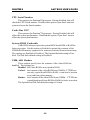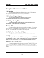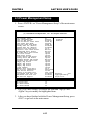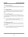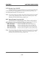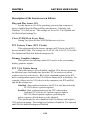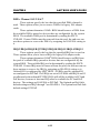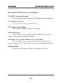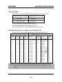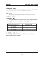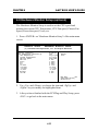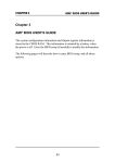
1
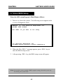
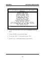
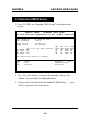
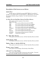
CHAPTER 4 AMI® BIOS USERS GUIDE Chapter 4 AMI® BIOS USER’S GUIDE The system configuration information and chipset register information is stored in the CMOS RAM. This information is retained by a battery when the power is off. Enter the BIOS setup (if needed) to modify this information. The following pages will describe how to enter BIOS setup, and all about options. 4-1 CHAPTER 4 AMI® BIOS USERS GUIDE 4.1 Enter BIOS Setup Enter the AMI® setup Program’s Main Menu as follows: 1. Turn on or reboot the system. The following screen appears with a series of diagnostic check. AMIBIOS (C) 1999 American Megatrends Inc. AGIOMS VXXX XXXXXX Hit <DEL> if you want to run setup (C) American Megatrends Inc. 61-XXXX-001169-00111111-071592-i82440FX-H 2. When the “Hit <DEL>” message appears, press <DEL> key to enter the BIOS setup screen. 3. After pressing <DEL> key, the BIOS setup screen will appear. Note: If you don’t want to modify CMOS original setting, then don’t press any key during the system boot. 4-2 CHAPTER 4 AMI® BIOS USERS GUIDE AMIBIOS HIFLEX SETUP UTILITIES - VERSION 1.22 (C) 1999 American Megatrends, Inc. All Rights Reserved Standard CMOS Setup Advanced CMOS Setup Advanced Chipset Setup Power Management Setup PCI/Plug and Play Setup Peripheral Setup Hardware Monitor Setup Auto-Detect Hard Disks Change User Password Change Supervisor Password Change Language Setting Auto Configuration with Optimal Settings Auto Configuration with Fail Safe Settings Save Settings and Exit Exit without Saving Standard CMOS setup for changing time, hard disk type, etc. 4. Use the <Up> and <Down> key to move the highlight scroll up or down. 5. Use the <ENTER> key to select the option. 6. To exit, press <ESC>. To save and exit, press <F10>. 7. Section 3.2 to 3.7 will explain the option in more details. 4-3 CHAPTER 4 AMI® BIOS USERS GUIDE 4.2 Standard CMOS Setup 1. Press <ENTER> on “Standard CMOS Setup” of the main menu screen . AMIBIOS SETUP - STANDARD CMOS SETUP (C)1999 American Megatrends,Inc.All Rights Reserved Date (mm/dd/yyyy): Time (hh/mm/ss): Fri March 20, 1999 17:09:25 Floppy Drive A: Floppy Drive B: 1.44 MB 3 1/2 Not Installed Pri Pri Sec Sec Master Slave Master Slave Type :Auto :Auto :Auto :Auto Size Cyln Boot Sector Virus Protection Month Day Year Head WPcom Sec LBA Mode ON ON ON ON Blk Mode ON ON ON ON PIO Mode AUTO AUTO AUTO AUTO 32Bit Mode ON ON ON ON Disabled : Jan-Dec : 01-31 : 1901-2099 ESC:Exit :Sel PgUp/PgDn:Modify F2/F3:Color 2. Use <Up> and <Down> to choose the item and <PgUp> and <PgDn> keys to modify the highlighted item. 3. After you have finished with the Standard CMOS Setup, <ESC> to go back to the main menu. 4-4 press CHAPTER 4 AMI® BIOS USERS GUIDE 4.3 Advanced CMOS Setup 1. Press <ENTER> on “Advanced CMOS Setup” of the main menu AMIBIOS SETUP - ADVANCED CMOS SETUP (C) 1999 American Megatrends, Inc. All Rights Reserved Quick Boot Ist Boot Device 2nd Boot Device 3rd Boot Device Try Other Boot Devices Initial Display Mode Display Mode at Add-On ROM Init Floppy Access Control S.M.A.R.T. For Hard Disk BootUp Num-Lock Floppy Drive Swap Floppy Drive Seek PS/2 Mouse Support Primary Display Password Check Boot to OS/2 > 64M CPU Serial Number Cache Bus ECC System BIOS Cacheable C000, 64k Shadow Enabled Floppy IDE 0 CD-ROM Yes BIOS Force-BIOS Read-Write Disabled On Disabled Disabled Enabled VGA/EGA Setup No Disabled Enabled Disabled Enabled Available Options: Disabled Enabled ESC:Exit :Sel PgUp/PgDn:Modify F2/F3:Color 2. Use <Up> and <Down> to choose the item and <PgUp> and <PgDn> keys to modify the highlighted item. 3. After you have finished with the Advanced CMOS Setup, press <ESC> to go back to the main menu. 4-5 CHAPTER 4 AMI® BIOS USERS GUIDE Description of the item on screen follows: Quick Boot Set this option to Enabled to permit AMI® BIOS to boot within 5 seconds. This option replaces the old ABOVE 1 MB Memory Test option. The Optimal default setting is Enabled. The Fail-Safe default setting is Disabled. 1st Boot Device/2nd Boot Device/3rd Boot Device This option sets the sequence of boot drives. The settings are: IDE0 The system will boot from the first HDD. IDE1 The system will boot from the Second HDD. IDE2 The system will boot from the Third HDD. IDE3 The system will boot from the Fourth HDD. F(optical) The system will boot from LS-120(120M Floppy). SCSI The system will boot from the SCSI. Network The system will boot from the Network drive. CD-ROM The system will boot from the CD-ROM. Disable Disable this sequence. Try other Boot Devices This option sets the device boot, if all the Four Boot Devices failed. Initial Display Mode This option sets the device boot, if all the Four Boot Devices failed. Display Mode at Add-On ROM Init This option sets the device boot, if all the Four Boot Devices failed. Floppy Access Control This option sets the Floppy to Read-only or Read-Write. S.M.A.R.T. for Hard Disks This option sets the SMART Function for the hard disk. The hard disk need to have SMART function for this feature to work. 4-6 CHAPTER 4 AMI® BIOS USERS GUIDE Boot up Num Lock When this option is set to Off, AMI® BIOS turns off the Num Lock key when the system is powered on. The end user can then use the arrow keys on both the numeric keypad and the keyboard. The settings are On or Off. The optimal default and Fail-Safe default settings are On. Floppy Drive Swap Set this option to Enabled to specify that floppy drives A: and B: are swapped. The setting are Enabled and Disabled. The Optimal and Fail-Safe default settings are Disabled. Floppy Drive Seek When this option is set to Enabled, AMI® BIOS performs a Seek command on floppy drive A: before booting the system. The settings are Enabled and Disabled. The Optimal and Fail-Safe default settings are Disabled. PS/2® Mouse Support When this option is set to Enabled, AMI® BIOS supports a PS/2® mouse. The settings are Enabled and Disabled. The Optimal and Fail-Safe default settings are Enabled. Primary Display This option configures the primary display subsytem in the computer. The settings are Mono(monochrome), 40CGA, 80CGA or VGA/EGA. The optimal and Fail-Safe default settings are VGA/EGA. Password Check This option specifies the type of AMI® BIOS password protection that is implemented. The Optimal and Fail-Safe default settings are Setup. Boot To OS/2® > 64MB Set this option to Enabled to permit the BIOS to run properly, if OS/ 2® is to be used with > 64MB of DRAM. The settings are Enabled or Disabled. The Optimal and Fail-safe default settings are Disabled. 4-7 CHAPTER 4 AMI® BIOS USERS GUIDE CPU Serial Number This option is for Pentium III processor. During Enabled, this will check the CPU Serial number. Disabled this option if you don’t want the system to know the Serial number. Cache Bus ECC This option is for Pentium® II processor. During Enabled, this will affect the system performance. Disabled this option if you don’t want to affect the system performance. System BIOS Cacheable AMI® BIOS always copies the system BIOS from ROM to RAM for faster execution. Set this option to Enabled to permit the contents of the F0000h RAM memory segment to be written to and read from cache memory. The settings are Enabled or Disabled. The Optimal default setting is Enabled. The Fail-Safe default setting is Disabled. C000, 64K Shadow These options specify how the contents of the video ROM are handled. The settings are: Disabled - the Video ROM is not copied to RAM. Cached - the contents of the video ROM from C0000h - C7FFFh are not only copied from ROM to RAM; it can also be written to or read from cache memory. Shadow - the Contents of the video ROM from C0000h - C7FFFh are copied(shadowed) from ROM to RAM for faster execution. The Optimal and Fail-Safe default setting is Cached. 4-8 CHAPTER 4 AMI® BIOS USERS GUIDE 4.4 Advanced Chipset Setup 1. Press <ENTER> on “Advanced Chipset Setup” of the main menu screen. AMIBIOS SETUP - ADVANCED CHIPSET SETUP (C) 1999 American Megatrends, Inc. All Rights Reserved USB Function USB Keyboard Legacy Support CPU Latency Timer DRAM Page Closing Policy CD Hole (DC000h - DFFFh) Memory Hole DRAM Tras/Trc Cycle Time(SCLKs) Address Setup Time(SCLKs) CAS# Latency(SCLKs) SDRAM RAS# to CAS# Delay(SCLKs) SDRAM RAS# Precharge Graphics Mode Select Onboard Video Chip CPU BIST Enable ICH Delayed Transaction ICH DCB Enable ****Display Cache Function**** Initialize Display Cache Memory Paging Mode Control RAS-to-CAS CAS Latency RAS Timing RAS Precharge Timing Enabled Disabled Disabled Closed Disabled Disabled 6/8 1 3 3 3 UMA 1MB Enabled Disabled Disabled Disabled Enabled Closed Default Available Options: Disabled Enabled ESC:Exit :Sel PgUp/PgDn:Modify F2/F3:Color Slow Slow Slow 2. Use <Up> and <Down> to choose the item and <PgUp> and <PgDn> keys to modify the highlighted item. 3. After you have finished with the Advanced Chipset Setup, press <ESC> to go back to the main menu. 4-9 CHAPTER 4 AMI® BIOS USERS GUIDE Description of the item on screen follows: USB Function Set this option to Enabled or Disabled the on-chip USB controller. The Optional and Fail-Safe default settings are Disabled. USB Keyboard Legacy Support Set this option to Enabled or Disabled USB keyboard. The Optional and Fail-Safe default settings are Disabled. DRAM Page Closing Policy This option controls whether the GMCH will precharge bank or precharge all, during the service of a page miss. Memory Hole This option allows the end user to specify the location of a memory hole. The cycle matching the selected memory hole will be passed to the ISA bus. If Enabled, the selected hole is not remapped. DRAM Tras/Trc Cycle Time (SCLKs) This option controls the number of SCLKs for an access cycle. CAS# Latency This option determines the CAS latency time parameter of SDRAM. The settings are 2 clks or 3 clks. Under 66MHz CPU bus, set this option to either 2 or 3 but for 100MHz CPU, it is recommended that this be set to 3. SDRAM RAS# to CAS# Delay This operation decide the delay in assertion of CAS#(SCAS#) from assertion of RAS#(SRAS#) in 66MHz. Under 66MHz CPU bus, set this option to either 2 or 3 but for 100MHz CPU, it is recommended that this be set to 3. 4-10 CHAPTER 4 AMI® BIOS USERS GUIDE SDRAM RAS Precharge This option defines the RAS# precharge requirements for the SDRAM memory type in 66MHz clocks. Under 66MHz CPU bus, set this option to either 2 or 3 but for 100MHz CPU, it is recommended that this be set to 3. Graphics Mode Select This option is used to enable/Disable the internal graphics device and select the amount of system memory that is used to support the internal graphics device. Onboard Video Chip This option is used to enable/disabled the video onboard the chip. Initialize Display Cache Memory This option will allow you to initialized the display cache memory. Paging Mode Control This option decide the GMCH memory controller tends to leave pages open or closed. RAS-to-CAS This option determine the display cache RAS#-toCAS# delay. CAS# Latency This option decide the display cache CAS latency. RAS# Timing This option controls RAS# active to precharge, and refresh to RAS# active delay. RAS# Precharge Timing This option controls RAS# precharge clocks. 4-11 CHAPTER 4 AMI® BIOS USERS GUIDE 4.5 Power Management Setup 1. Press <ENTER> on “Power Management Setup” of the main menu screen. AMIBIOS SETUP - POWER MANAGEMENT SETUP (C) 1999 American Megatrends, Inc. All Rights Reserved ACPI Standby State Power Management/APM Green PC LED Status Green PC Monitor Power State Video Power Down Mode Hard Disk power Down Mode Standby Time Out (Minute) Suspend Time Out (Minute) Throttle Slow Clock Ratio Keyboard & PS/2 Mouse Access FDC/LPT/COM Ports Access SB & MSS Audio Ports Access Midi Ports Access ADLIB Ports Access Primary Master IDE Access Primary Slave IDE Access Secondary Master IDE Access Secondary Slave IDE Access PIRQ[A] IRQ Active PIRQ[B] IRQ Active PIRQ[C] IRQ Active PIRQ[D] IRQ Active System Thermal Thermal Slow Clock Ratio CPU Critical Temperature Power Button Function Restore on AC/Power Loss Ring Resume from Soft Off LAN Resume from Soft Off PME Function Support S1 Enabled Blinking Stand By Suspend Stand By Disabled Disabled 50.0% Monitor Monitor Ignore Ignore Ignore Monitor Ignore Monitor Ignore Ignore Ignore Ignore Ignore Ignore 50.0% 650C/1490F On/Off Last State Disabled Disabled Disabled RTC RTC RTC RTC RTC Disabled 15 12 30 30 Alarm Alarm Alarm ALarm Alarm Resume from Soft Off Date Hour Minute Second Available Options: Disabled Enabled ESC:Exit :Sel PgUp/PgDn:Modify F2/F3:Color 2. Use <Up> and <Down> to choose the item and <PgUp> and <PgDn> keys to modify the highlighted item. 3. After you have finished with the Power Management Setup, press <ESC> to go back to the main menu. 4-12 CHAPTER 4 AMI® BIOS USERS GUIDE Description of the item on screen follows: ACPI Standby State This option sets the ACPI Power Management Standby State. S1 Sleeping State The S1 sleeping state is low wake-up latency sleeping state. In this state, no system context is lost(CPU or chip set) and hardware maintains all system context. S3 Sleeping State The S3 state is a low wake-up latency sleeping sate where all system context is lost expect system memory. CPU, cache, and chipset context are lost in this state. Hardware maintains memory context and restores some CPU and L2 configuration context. Power Management/APM Set this option to Enabled to enable the chipset’s power management features and APM(Advanced Power Management). The settings are Enabled, Inst-On(instant-on) or Disabled. The Optimal and Fail-Safe default settings are Disabled. Green PC LED Status This option specifies the power state that the green PC-compliant video monitor enters when AMI® BIOS places it in a power savings state after the specified period of display inactivity has expired. The settings are Off, Standby, Suspend or Disabled. The Optimal and Fail-Safe default settings are Standby. Green PC Monitor Power State This option specifies the power state that the green PC-compliant video monitor enters when AMI® BIOS places it in a power savings state after the specified period of display inactivity has expired. The settings are Off, Standby, Suspend or Disabled. The Optimal and Fail-Safe default settings are Standby. 4-13 CHAPTER 4 AMI® BIOS USERS GUIDE Video Power Down Mode This option specifies the power conserving state that the VESA VGA video subsystem enters after the specified period of display inactivity has expired. The settings are Disabled, Standby or Suspend. The Optimal and Fail-Safe default settings are Standby. Hard Disk Power Down Mode This option specifies the power conserving state that the hard disk drive enters after the specified period of hard drive inactivity has expired. The settings are Disabled, Standby or Suspend. The Optimal and Fail-Safe default settings are Disabled. Standby Time Out (Minute) This option specifies the length of a period of system inactivity while in Standby state. When this length of time expires, the computer enters Suspend power state. The settings are Disabled, 1 min, 2 min, 3 min, 4 min, 5 min, 6 min, 7 min, 8 min, 9 min, 10 min, 11 min, 12 min, 13 min, 14 min or 15 min. The Optimal and Fail-Safe default settings are Disabled. Suspend Time Out (Minute) This option specifies the length of a period of system inactivity while in Suspend state. When this length of time expires, the computer enters Suspend power state. The settings are Disabled, 1 min, 2 min, 3 min, 4 min, 5 min, 6 min, 7 min, 8 min, 9 min, 10 min, 11 min, 12 min, 13 min, 14 min or 15 min. The Optimal and Fail-Safe default settings are Disabled. Throttle Slow Clock Ratio This option specifies the speed at which the system clock runs in power saving states. The settings are expressed as a ratio between the normal CPU clock speed and the CPU clock speed when the computer is in the power-conserving state. Thermal Slow Clock Ratio When set to Monitor, then you can choose the throttle ratio. This option is connected with the CPU Critical Temperature Option. 4-14 CHAPTER 4 AMI® BIOS USERS GUIDE CPU Critical Temperature This option is for setting the CPU temperature that would be critical enough, so that it would use the Thermal Slow Clock Ratio to cool down the CPU. Power Button Function During Suspend, if you push the switch once, the system goes into suspend mode and if you push it more than 4 seconds, the system will be turned off. During On/Off, the system will turn off once you push the switch. Restore on AC/Power Loss The settings are power on or last status. During power on, after every AC power loss, the system will be turned on. During last status, after every AC power loss, whatever the system status, it will be the same when the AC power returns. Note: a. If you set this option to last status, the Power Button Function must be set to On/Off, or this function will not work. b. Jumper JP1 must always be open, for this function to work properly. Ring Resume from Soft-Off During Disabled, the system will ignore any incoming call from the modem. During Enabled, the system will boot up if there’s an incoming call from the modem. Note: If you have change the setting, you must let the system boot up until it goes to the operating system. Then, power off the system. This function will work the next time you power on. 4-15 CHAPTER 4 AMI® BIOS USERS GUIDE LAN Resume from Soft-Off During Disabled, the system will ignore any incoming signal from the LAN network card. During Enabled, the system will boot up if there’s an incoming signal from the LAN network card. Note: If you have change the setting, you must let the system boot up until it goes to the operating system. Then, power off the system. This function will work the next time you power on. RTC Alarm Resume From Soft-Off This function is for setting the Date, Hour, Minute, and Second for your computer to boot up. During Disabled, you cannot use this function. During Enabled, Choose the Date, Hour, Minute, and Second: RTC Alarm Date Choose which day the system will boot up. RTC Alarm Hour Choose which hour the system will boot up. RTC Alarm Minute Choose which minute the system will boot up. RTC Alarm Second Choose which second the system will boot up. Note: If you have change the setting, you must let the system boot up until it goes to the operating system. Then, power off the system. This function will work the next time you power on. 4-16 CHAPTER 4 AMI® BIOS USERS GUIDE 4.6 PCI/Plug and Play Setup 1. Press <ENTER> on “PCI/Plug and Play Setup” of the main menu screen. AMIBIOS SETUP - PCI/PLUG AND PLAY SETUP (C) 1999 American Megatrends, Inc. All Rights Reserved Plug and Play Aware O/S Clear NVRAM PCI Latency Timer (PCI Clocks) Primary Graphics Adapter PCI VGA Palette Snoop DMA Channel 0 DMA Channel 1 DMA Channel 3 DMA Channel 5 DMA Channel 6 DMA Channel 7 IRQ3 IRQ4 IRQ5 IRQ7 IRQ9 IRQ10 IRQ11 IRQ14 IRQ15 No No 64 Add-On VGA Disabled PnP PnP PnP PnP PnP PnP PCI/PnP PCI/PnP PCI/PnP PCI/PnP PCI/PnP PCI/PnP PCI/PnP PCI/PnP PCI/PnP Available Options: Enabled Disabled ESC:Exit :Sel PgUp/PgDn:Modify F2/F3:Color 2. Use <Up> and <Down> to choose the item and <PgUp> and <PgDn> keys to modify the highlighted item. 3. After you have finished with the PCI/Plug and Play Setup, press <ESC> to go back to the main menu. 4-17 CHAPTER 4 AMI® BIOS USERS GUIDE Description of the item on screen follows: Plug and Play Aware O/S Set this option to Yes if the operating system in this computer is aware of and follows the Plug and Play specification. Currently, only Windows® 95 is PnP-aware. The settings are Yes or No. The Optimal and Fail-Safe default settings No. Clear NVRAM on Every Boot During Yes, this will clear NVRAM data on every boot. PCI Latency Timer (PCI Clocks) This option specifies the latency timings (in PCI clocks) for all PCI devices on the PCI bus. The settings are 32, 64, 96, 128, 160, 192, 224 or 248. The Optimal and Fail-Safe default settings are 64. Primary Graphics Adapter This option is for selecting which VGA card is to be your primary display graphics adapter. PCI VGA Palette Snoop When this option is set to Enabled, multiple VGA devices operating on different buses can handle data from the CPU on each set of palette registers on every video device. Bit 5 of the command register in the PCI device configuration space is the VGA Palette Snoop bit (0 is disabled). For example, if there are two VGA devices in the computer (one PCI and ISA) and the Bit settings are: Disabled - Data read and written by the CPU is only directed to the PCI VGA device’s palette registers. Enabled - Data read and written by the CPU is directed to both the PCI VGA device’s palette registers and the ISA VGA device palette registers, permitting the palette registers of both devices to be identical. This option must be set to Enabled if an ISA adapter card requires VGA palette snooping. The settings are Enabled or Disabled. The Optimal and Fail-Safe default settings are Disabled. 4-18 CHAPTER 4 AMI® BIOS USERS GUIDE DMA Channel 0/1/3/5/6/7 These options specify the bus that the specified DMA channel is used. These options allow you to reserve DMAs for legacy ISA adapter cards. These options determine if AMI® BIOS should remove a DMA from the available DMAs passed to devices that are configurable by the system BIOS. The available DMA pool is determined by reading the ESCD NVRAM. If more DMAs must be removed from the pool, the end user can use these options to reserve the DMA by assigning an ISA/EISA setting to it. IRQ3/IRQ4/IRQ5/RQ7/IRQ9/IRQ10/IRQ11/IRQ14/IRQ15 These options specify the bus that the specified IRQ line is used on. These options allow you to reserve IRQs for legacy ISA adapter cards. These options determine if AMI® BIOS should remove an IRQ from the pool of available IRQs passed to devices that are configurable by the system BIOS. The available IRQ pool is determined by reading the ESCD NVRAM. If more IRQs must be removed from the pool, the end user can use these options to reserve the IRQ by assigning an ISA/EISA setting to it. Onboard I/O is configured by AMI® BIOS. All IRQs used by onboard I/O are configured as PCI/PnP. If all IRQs are set to ISA/EISA and IRQ14 and 15 are allocated to the onboard PCI IDE, IRQ9 will still be available for PCI and PnP devices, because at least one IRQ must be available for PCI and PnP devices. The settings are ISA/EISA or PCI/PnP. The Optimal and Fail-Safe default settings are IRQ3 through 7 are ISA/EISA. The Optimal and Fail-Safe default settings PCI/PnP. 4-19 CHAPTER 4 AMI® BIOS USERS GUIDE 4.7 Peripheral Setup 1. Press <ENTER> on “Peripheral Setup” of the main menu screen. AMIBIOS SETUP - PERIPHERAL SETUP (C) 1999 American Megatrends, Inc. All Rights Reserved CLKGEN Spread Spectrum CPU Ratio Selection CPU Host Clock (Mhz) Onboard Sound Onboard AC’97 Audio Onboard AC’97 Modem Onboard IDE Onboard FDC Onboard Serial Port A Onboard Serial Port B Serial Port B Mode IR Duplex Mode IR Pin Select Onboard CIR Port CIR IRQ Select Onboard Parallel Port Parallel Port Mode EPP Version Parallel Port IRQ Parallel Port DMA Channel Onboard Midi Port Midi IRQ Select Onboard Game Port Mouse PowerOn Function Keyboard PowerOn Function Specific Key for Power On Available Options: Enabled Auto 3.0x Disabled Auto Enabled Enabled Enabled Disabled Both Auto Auto Auto Normal Half Duplex IRRX/IRTX Disabled 10 Auto ECP N/A Auto Auto Disabled ESC:Exit :Sel 9 PgUp/PgDn:Modify Disabled F2/F3:Color Disabled Disabled N/A 2. Use <up> and <down> to choose the item and <PgUp> and <PgDn> keys to modify the highlighted item. 3. After you have finished with the Peripheral Setup, press <ESC> to go back to the main menu. 4-20 CHAPTER 4 AMI® BIOS USERS GUIDE Description of the item on screen follows: CLKGEN Spread Spectrum This item allows you to set the CPU clock generator spread spectrum. CPU Ratio Selection This item allows you to set the CPU ratio. CPU Host Clock (MHz) This item allows you to set the CPU host clock. Onboard Sound This item allows you to enable/disable the onboard Aureal audio chipset. The settings are Enabled, Disabled. Onboard AC’97 Audio/Onboard AC’97 Modem This item allows you to decide to enable/disable the 810 chipset family to support AC97 Audio/Modem. The settings are Enabled, Disabled. Onboard IDE Set this option to enable or disable on board IDE controller. 4-21 CHAPTER 4 AMI® BIOS USERS GUIDE Onboard FDC Choose Auto, for the BIOS to automatically detect the device If the ISA add-on card has Onboard FDC to be set at FDC exist Disabled none FDC exist Enabled Choose Enabled, Enabling onboard FDC. Choose Disabled, Disabling onboard FDC. The Optimal and Fail-Safe default settings are Auto. Onboard Serial Port A/Onboard Serial Port B Choose 3F8, for the BIOS to automatically detect the device. If the ISA add-on card has COM4 COM3 COM2 COM1 (I/O:3F8H) (I/O:3F8H) (I/O:3E8H) (I/O:2E8H) ü ü X ü X ü ü ü X X ü X X X ü ü X X ü ü ü X ü X X ü X X ü X ü X ü ü X ü ü X X X ü X ü X ü ü X X ü ü ü X X X X ü Onboard Serial port to be set at PORT1 DISABLED COM3 COM1 COM2 COM1 COM4 COM3 COM2 COM1 COM1 COM2 COM1 COM1 COM1 IRQ ASSIGNED X 4 4 3 4 3 4 3 4 4 3 4 4 4 PORT2 DISABLED COM4 COM2 COM3 COM4 DISABLED DISABLED DISABLED DISABLED COM2 COM3 COM3 COM2 COM2 IRQ ASSIGNED X 3 3 4 3 X X X X 3 4 4 3 3 Note: If the onboard serial port interrupt and ISA add-on card interrupt are in conflict, the serial port will not work properly. Please disable one of the devices. 4-22 CHAPTER 4 AMI® BIOS USERS GUIDE Serial PortB Mode Choosing Normal will set the Serial Port B for normal use, not for IR device. Choosing IrDA or Ask IR will set it for use with IR device using these protocols. IR Duplex Mode Can be set as either Half or Full duplex. IR Pin Select Set this option to IRRX/IRTX when using an internal IR device which is connected to IR1 connector. Onboard Parallel Port Choose Auto, the BIOS automatically assigned onboard parallel port to the available parallel port or disabled. If the ISA add-on card has Onboard parallel port to be set as LPT1 LPT2 LPT3 I/O:378H I/O:278H I/O:3BCH ü ü ü ü ü X ü X ü X ü ü ü X X X ü X X X ü X X X PORT ASSIGNED Disabled LPT3 LPT2 LPT1 LPT2 LPT1 LPT1 LPT1 IRQ ASSIGNED X 5 5 7 5 7 7 7 Note: If the onboard parallel port interrupt and ISA add-on card interrupt are in conflict, the parallel port will not work properly. Please disable one of the devices. 4-23 CHAPTER 4 AMI® BIOS USERS GUIDE Parallel Port Mode This option allows user to choose the operating mode of the onbaord parallel port. The settings are Normal, SPP/EPP or ECP mode. EPP Version This option is for setting which EPP version will be used. The settings are 1.7 and 1.9. Parallel Port IRQ If the onboard parallel mode is not on auto mode, the user can select the interrupt line for onboard parallel port. We suggest that the user select the interrupt for the onboard parallel port as shown below: Parallel Port IRQ Onboard parallel port set at LPT1(378H) 7 LPT2(278H) 5 LPT3(3BCH) 5 Parallel Port DMA Channel This option allows user to choose DMA channel 1 to 3 for the onboard parallel port on ECP mode. 4-24 CHAPTER 4 AMI® BIOS USERS GUIDE 4.8 Hardware Monitor Setup (optional) The Hardware Monitor Setup is used to set the CPU speed and monitor the current CPU Temperature, CPU Fan speed, Chassis Fan Speed, Power fan speed, Vcore, etc. 1. Press <ENTER> on “Hardware Monitor Setup” of the main menu screen. AMIBIOS SETUP - HARDWARE MONITOR SETUP (C) 1999 American Megatrends, Inc. All Rights Reserved Chassis Intrusion CPU Temperature Detected By CPU Temperature System Temperature CPU Fan Speed CPU VID Vcore Vtt Vio +5,000V +12,000V -12,000V -5,000V Battery +5V SB Disabled CPU 46 0C/114 0 F 31 oC/87 oF 4560 RPM 2.00V 1.936V 2.480V 3.280V 5.113V 12.045V -11.763V -4.932V 3.00V 5.60V Available Options: Manual Auto ESC:Exit :Sel PgUp/PgDn:Modify F2/F3:Color 2. Use <Up> and <Down> to choose the item and <PgUp> and <PgDn> keys to modify the highlighted item. 3. After you have finished with the PCI/Plug and Play Setup, press <ESC> to go back to the main menu. 4-25