1
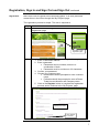
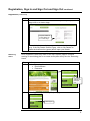
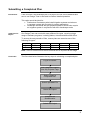
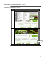
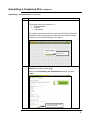
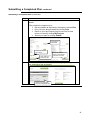
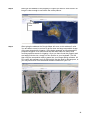
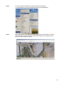
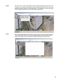
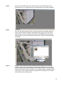
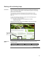
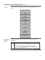
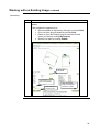
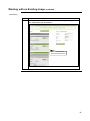
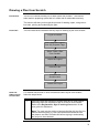
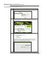
Irrigation Planner
User Guide
Table of Contents
Irrigation Planner User Guide ..................................................................................................3
Overview............................................................................................................................3
Irrigation Planner Users .....................................................................................................4
Registration, Sign In and Sign Out .....................................................................................5
Gathering Site Information ...............................................................................................10
Submitting a Completed Plan ...........................................................................................11
How to obtain an image ...................................................................................................17
Working with an Existing Image .......................................................................................22
Drawing a Plan from Scratch ...........................................................................................31
Drawing with the Planner .................................................................................................35
Questionnaire ..................................................................................................................48
My Projects ......................................................................................................................52
What Happens After I Submit My Plan? ...........................................................................54
Frequently Asked Questions ............................................................................................56
2
Irrigation Planner User Guide
Overview
Introduction
This document has been created to assist with the On Line Irrigation Planner.
It provides information on how to create a plan, as well as how to provide the
relevant details required by the Design Team to prepare a well designed,
uniform and efficient watering system for you.
This guide covers a number of areas, including:
• Registration and sign in
• Obtaining site information
• Submitting a completed plan
• Working with an existing imported drawing
• Creating a plan from scratch
• How to track your project or quote
• Options for your ‘My Projects’ page
3
Irrigation Planner Users
Users
The Irrigation Planner has been designed to be used by two key groups,
Professionals and Home Owners, defined as:
User
Professionals
Homeowners
Definition
A contractor who installs irrigation systems as either:
• Core business
• Part of the business (i.e. Landscaper, Grower,
Local Shire/Council)
The proposed irrigation system is for their own home and
they intend to either:
• Complete and install the system themselves
• Have control over the proposed irrigation system
and engage the services of a professional
contractor to install the system only.
Note: All Reece Irrigation Branches can assist users with
potential contractors for this process.
4
Registration, Sign In and Sign Out
Introduction
To access the My Projects page and submit plans, users first need to
register. You do not need to register and sign-in immediately. You may first
familiarise yourself with the Irrigation Planner.
User Guide
For instructions on how to use the Irrigation Planner, the user can download
the Irrigation Planner User Guide. To download, click ‘Downloading the
Irrigation Planner User Guide’.
Click to download
the Irrigation Planner
User Guide
continued on next page
5
Registration, Sign In and Sign Out continued
Using the
Planner Before
Registration
To become familiar with the Irrigation Planner without registering, enter the
site as either a Professional or a Home Owner.
Note: Before submitting any plans you must be registered.
Click here to enter
as a Professional
Click here to enter
as a Homeowner
Click Draw Your Plan to enter the On Line Planner and become familiar with
the layout and tools.
Click ‘Draw Your
Plan’ to familiarise
yourself with the
planner
When finished users will need to either:
• Complete the registration process to submit the plan, or
• Delete the plan and come back to register later.
Refer to the ‘Draw a Plan From Scratch’ section of this User Guide for more
details on how to use the On Line Planner.
continued on next page
6
Registration, Sign In and Sign Out and Sign Out continued
Registration
New users need to register before submitting plans, or to save plans and
access them in the future through the ‘My Projects’ page.
The registration process is simple. The user is required to:
Step
1.
Action
Click on Click here to register under New Users to open the
Registration page
Click here to open
registration page
2.
Complete the required information on the registration page:
1. Enter a valid email address.
2. Enter a password
• Passwords can be numbers, letters or a
combination of both.
• Passwords must be a minimum of 6 characters
3. Confirm your password
4. Choose your customer type:
• Homeowners will be prompted to enter a contact
name
• Professionals will be prompted to enter a Reece
Trade Account Number and Company name
5. Click on the Register button to complete the registration
process and to continue to the ‘My Projects’ page
Complete the
required information
Click ‘Register’
to continue
continued on next page
7
Registration, Sign In and Sign Out and Sign Out continued
Registration (continued)
Step
3.
Action
You may enter additional contact details in your ‘My Projects’
page now or at a later stage.
Complete additional
contact details now
or at a later stage
Note: Active buttons display as green. Inactive buttons display as
grey. If the ‘My Details’ button is grey, click on ‘My Details’ to
make the button active (green) and to open your details.
Returning
Users
Once registered, users may return to the ‘My Projects’ page to continue
working on an existing plan or to create a new plan at any time via ‘Returning
Users’.
Step
1.
Action
Under ‘Returning Users’ enter:
• Email address
• Password
Enter email
address and
password
here
2.
Click Sign In to go to the My Projects page.
Click ‘Sign In’
continued on next page
8
Registration, Sign In and Sign Out continued
Signing Out
To sign out and exit your My Projects page, simply click Sign Out.
Click ‘Sign Out’
9
Gathering Site Information
Introduction
To effectively prepare a drawing for submission, you will first need to gather
some important site information.
Getting Started
To assist with gathering site information, download our handy ‘Before You
Start’ instruction sheet. Simply click to download, follow the prompts and then
print to take it on site with you.
Note: The instruction sheet is also accessible from the Irrigation Planner
home page.
Click ‘Instruction Sheet’
on the Home page
Obtaining Site
Information
Tips
Here are some handy tips to assist you to gather relevant site information:
• Always work from a fixed point of reference with known 90° angles,
such as a house or shed
• Initial drawings (when on-site) do not have to be to scale until you
reproduce them on the on line planner.
Note: they must have measurements marked on each line, as well
as additional measurements showing the spacing between structures.
E.g. Distance across a lawn area to a building
Note: Drawings created within the On Line Planner must be to scale.
10
Submitting a Completed Plan
Introduction
If the user has a full landscape plan of a project, the file can be attached and
sent to our Design Team to be used to create a detailed quotation.
This option would be ideal for:
• Professional Contractors who install irrigation systems and who are
in constant contact with Councils for tender applications
• Landscape Architects with pre-prepared plans for clients who require
an irrigation system in conjunction with their Landscape works
Valid Files for
Import
Our Design Team can work with many different file types, covering a large
range of software programs, including Adobe, Autocad and Microsoft Office.
To ensure the easy transfer of files, ensure plans are saved as one of the
following file types:
.bmp
.dwg
.pcx
.jpeg
.dxf
.pdf
.doc
.gif
.tif
.docx
.jpg
.txt
.gcd
.vcd
.wmf
.zip
.xls
.xlsx
Note: There is a 5mb limit on the file size that can be imported at this stage.
Flow Chart
The flow chart below illustrates the key steps in submitting a completed plan:
Log-In to Planner
Click ‘Start New Project’
from ‘My Projects’ Page
Select ‘Submit a
Completed Plan’
Submit Uploaded File
Name the Project
Complete the
Questionnaire
Submit the Project
continued on next page
11
Submitting a Completed Plan continued
Submitting a
Completed Plan
For detailed instructions on how to submit a completed plan, follow the steps
below:
Step
1.
2.
Action
Ensure you have signed into the On Line Planner as a returning
user.
Note: If using the planner for the first time you will need to
register. Refer to the Registration and Sign In section of this
user guide for assistance.
Click on Start New Project from your My Projects screen.
Click ‘Start
New Project’
3.
Locate the Submit a Completed Plan box on your Home screen
(either Professional or Homeowner) and click Choose File.
Click ‘Choose File’ to
open a Windows box
This will open a Windows box where you can select your file.
continued on next page
12
Submitting a Completed Plan continued
Submitting a Completed Plan (continued)
Step
4.
Action
Select the file you wish to upload and then click Open.
Select file and
click ‘Open’
5.
Click Submit to upload the file.
Click ‘Submit’
continued on next page
13
Submitting a Completed Plan continued
Submitting a Completed Plan (continued)
Step
6.
Action
Click Next to continue.
Your uploaded file will be visible in the Submit a Completed Plan
box.
Click ‘Next’
Note: If you have uploaded an incorrect file, you can delete it by
clicking the red minus button next to the uploaded file.
Click the red minus
button to delete the file
continued on next page
14
Submitting a Completed Plan continued
Submitting a Completed Plan (continued)
Step
7.
Action
Name the project and click Go
The project name may consist of a:
• Street address
• Suburb
• Job number
The project name will provide the user and the Design Team with
a specific name for the project and will help you to track multiple
projects on the My Projects page in the future.
Name your project
and Click ‘Go’
8.
Complete each page of the questionnaire. You will need to click
Next at the bottom of each page.
Refer to the Completing the Questionnaire section for more
details.
Click ‘Next’ after each page
of the questionnaire
continued on next page
15
Submitting a Completed Plan continued
Submitting a Completed Plan (continued)
Step
9.
Action
Once the questionnaire is complete you can preview the job
details.
This provides the opportunity to:
• Edit any details as required by clicking the relevant Edit
• Print your plan and job details by clicking Print
• Return to your My Projects page to save the file and
return to it later by clicking My Projects
• Submit your plan by clicking Submit
Click ‘Edit’ to
edit details
Click ‘Print’ to print
plan and job
Click ‘Submit’ to
submit the plan
10.
Click ‘My Projects
Page’ to save project
and return to it later
Once submitted, the user can see on the My Projects Page that
the submission was successful.
Details of the submitted
plan will be displayed here
16
How to obtain an image
Introduction
Online mapping web pages in particular Google can help users obtain an
image of their Project and then add additional drawing items such as new
garden beds, lawn areas to complete a proposed plan ready for irrigation.
The method below shows how this can be achieved using the Google maps
but can also be used for image software available OR a scan from your
home scanner that might have a Property title and New house Site survey.
These would also be useful as a starting point and then the online planner
can be used to build your landscape if no garden or lawns exist.
Step 1
Through your internet browser find this link http://maps.google.com.au/ to go
the Google Maps page.
Ensure Satellite
box is clicked to
show image.
Please note the Satellite Box is clicked to show actual images. (The Google
Maps are not always updated with any recent development or changes but
can show the boundary or hard structures to use the image as a base plan
and other items afterwards.
17
Step 2
Next type the address of the property or Project you wish to view to see if an
image is clear enough to use within the online planner.
Enter address
here.
Step 3
After typing the address the Google Maps will zoom to this address if valid.
You are able to zoom in and out to get as close and large as possible image
of the area intended for irrigation. In the below example we have based the
proposed irrigation off a commercial site that didn’t have too many trees
covering specifics areas for irrigation. Once you have found the property and
are happy with the size, simply hit Print Screen on your keyboard. This will
then copy the screenshot ready to paste into your image editing software. All
PCs come with software such as Paint which can be used for this purpose, or
you may have other more advanced software installed on your PC.
18
Step 4
On your windows Start Menu, locate through All Programs
>>>Accessories>>>Paint software and open up the application.
Step 5
After opening the Paint software locate through the menus Edit>>>>Paste
and click. This will now paste the screenshot image from Google into the
Paint Software ready for editing.
19
Step 6
We can edit or “crop” the image to suit the Property that we will work on. By
clicking on the dotted square symbol as marked in below this will cut just the
image we need to work on. Through Edit>>>>>Cut this will remove the parts
of the image outside the area we are most interested in.
Single click this
button to select
an area to copy.
Step 7
After the image has been removed we will now go to the top menus through
File>>>New (We don’t need to save changes) and we get a blank screen
again as though we have entered the Paint software for the first time.
20
Step 8
We can now through Paint go to the top menus, click Edit and then click
Paste and the “cut” image will now be inserted back into the Paint software.
Step 9
We now have the image we wish to use and can save this image ready for
import into the Reece Irrigation online planner. By going to our top menus
and clicking on File>>>>Save As we will see the dialog box where we can
simply type in the preferred filename and click the Type of file as JPEG and
click Save.
Step 10
When we have visited the Site to obtain other information such controller
location, power access, proposed pump and tank locations, flow rate and
pressures we simply need to measure just a single line that is on the image
and record with your other information. For example length of middle carpark
is 30 metres. The next part of the user guide will now explain how to import
this image into the online planner.
21
Working with an Existing Image
Introduction
Users can import an existing image into the On Line Planner as the basis for
a plan. The imported image can be re-scaled within the planner to accurately
reflect known site dimensions.
The image file is used as a base plan and is then traced over to fully
determine buildings, lines to mark differences between lawns and garden
beds, etc.
To assist with drawing a landscape to scale, the On Line Planner has a
function to import a scanned image of:
• Title block or House and Land drawings from a builder
• Google map images
Watch the demonstration video on the webpage or refer to the following
instructions for more information.
Click to watch a
demonstration
video
Valid Files for
Import
To ensure the easy transfer of files, ensure plans are saved as one of the
following file types:
.png
.jpeg
.jpg
.gif
Note: There is a 5mb limit on the file size that can be imported at this stage.
continued on next page
22
Working with an Existing Image continued
Flow Chart
The flow chart below illustrates the key steps in working with an existing
image:
Log-In to Planner
Click ‘Start New Project’
from ‘My Projects’ Page
Select ‘Work with an
Existing Image’
Import the Existing
Image
Name the Project
Trace/Draw the Plan
Complete the
Questionnaire
Submit the Project
Working With
an Existing
Image
For detailed instructions on how to work with an existing image, follow the
steps below:
Step
1.
Action
Ensure you have signed into the On Line Planner as a returning
user.
Note: If using the planner for the first time you will need to
register. Refer to the Registration, Sign In and Sign Out section
of this user guide for assistance.
continued on next page
23
Working with an Existing Image continued
Working With an Existing Image (continued)
Step
2.
Action
Click on Start New Project from your My Projects screen.
Click ‘Start
New Project’
3.
Locate the Work with an existing image box on your Home
screen (either Professional or Homeowner) and click Choose File
Click ‘Choose File’ to
open a Windows box
This will open a Windows box where you can select your file.
continued on next page
24
Working with an Existing Image continued
(continued)
Step
4.
Action
Select the file you wish to upload and then click Open.
Select file and
click ‘Open’
5.
Click Import to upload the file.
Click ‘Import’
continued on next page
25
Working with an Existing Image continued
(continued)
Step
6.
Action
Click Next to continue.
Click ‘Next’
Your uploaded file will be visible in the Submit a Completed Plan
box.
Note: If you have uploaded an incorrect file, you can delete it by
clicking the red minus button next to the uploaded file.
Click the red minus
button to delete the file
continued on next page
26
Working with an Existing Image continued
(continued)
Step
7.
Action
Name the project and click Go
The project name may consist of a:
• Street address
• Suburb
• Job number
The project name will provide the user and the Design Team with
a specific name for the project and will help you to track multiple
projects on the My Projects page in the future.
Name your project
and Click ‘Go’
8.
The imported image will open in the drawing canvas.
To define the scale:
• Click two known points on the image (points will appear as
red crosses)
• Enter the distance (in metres) between the points into the
box labelled Speficy Scale
• Click Set scale
2. Enter distance
1. Click two known
points on image
3. Click ‘Set
scale’
continued on next page
27
Working with an Existing Image continued
(continued)
Step
9.
Action
Confirm the scale is correct and click Yes.
Click ‘yes’ if
scale is correct
10.
The drawing tools are used to trace over the image and add
details. When the plan is complete, click next.
Refer to the section Drawing With the Planner for more details
on how to trace and add details.
When plan is
complete click ‘Next’
11.
Complete each page of the questionnaire. The user will need to
click Next at the bottom of each page.
Refer to the Completing the Questionnaire section for more
details.
Click ‘Next’ after each page
of the questionnaire
continued on next page
28
Working with an Existing Image continued
(continued)
Step
12.
Action
Once the questionnaire is complete you can preview the job
details.
This provides the opportunity to:
• Edit any details as required by clicking the relevant Edit
• Print your plan and job details by clicking Print
• Return to your My Projects page to save the file and
return to it later by clicking My Projects
• Submit your plan by clicking Submit
Click ‘Edit’ to
edit details
Click ‘Print’ to print
plan and job details
Click ‘Submit’ to
submit the plan
Click ‘My Projects
Page’ to save project
and return to it later
continued on next page
29
Working with an Existing Image continued
(continued)
Step
13.
Action
Once submitted, the user can see on the My Projects Page that
the submission was successful.
Details of the submitted
plan will be displayed here
30
Drawing a Plan from Scratch
Introduction
The On Line Planner allows you to draw a plan from scratch. The Planner
tools assist in preparing a plan that is in scale and of reasonable accuracy.
This section will take you through the process of drawing a plan, using the on
line tools, printing and submitting the plan.
Flow Chart
The flow chart below illustrates the key steps in drawing a plan from scratch:
Log-In to Planner
Click ‘Start New Project’
from ‘My Projects’ Page
Select ‘Draw a Plan
From Scratch’
Name the Project
Draw the Plan
Complete the
Questionnaire
Submit the Project
Draw and
Submit a Plan
from Scratch
For detailed instructions on how to draw and submit a plan from scratch,
follow the steps below:
Step
1.
Action
First time users are required to register with the On Line Planner.
Returning users are required to sign in to the On Line Planner.
Refer to the Registration, Sign In and Log Out section of this
user guide for assistance.
Note: The user has the option to become familiar with the On Line
Planner before signing in. User can familiarise themselves with
the planner and then hit Delete All before signing in and starting
the project to be submitted.
continued on next page
31
Drawing a Plan from Scratch continued
Draw and Submit a Plan from Scratch (continued)
Step
2.
Action
Click on Start New Plan on the My Projects screen.
Click ‘Start
New Project’
Locate the Draw a Plan from Scratch box on the Home screen
(either Professional or Homeowner) and click Draw Your Plan to
open the planner.
3.
Click to draw a
plan from scratch
4.
Name your project and click Go to continue.
The project name may consist of a:
• Street address
• Suburb
• Job number
The project name will provide you and the Design Team with a
specific name for your project and will help you track multiple
projects on your My Projects page in the future.
Name your project
and Click ‘Go’
continued on next page
32
Drawing a Plan from Scratch continued
Draw and Submit a Plan from Scratch (continued)
Step
5.
Action
Complete the plan and click Next. This takes the user to the
questionnaire.
Refer to Drawing with the Planner for information on how to
draw a plan with the drawing tools.
Click ‘Next’ after
completing your
plan
6.
Note: Ensure you save your plan into the My Projects page for
future reference if you are unable to complete the plan in one
sitting. Refer to the Save Function section for more details.
Complete each page of the questionnaire. Click Next at the
bottom of each page.
Refer to the Completing the Questionnaire section for more
details.
Click ‘Next’ after each page
of the questionnaire
continued on next page
33
Drawing a Plan from Scratch continued
Draw and Submit a Plan from Scratch (continued)
Step
7.
Action
Once the questionnaire is complete, you will be able to preview
your job details.
You can:
• Edit any details as required by clicking the relevant Edit
• Print your plan and job details by clicking Print
• Return to the My Projects page to save the file and return
to it later by clicking My Projects
• Submit the plan by clicking Submit
Click ‘Edit’ to
edit details
Click ‘Print’ to print
plan and job details
Click ‘Submit’ to
submit the plan
8.
Click ‘My Projects
Page’ to save project
and return to it later
When you submit your plan you will be taken to your My Projects
Page where you will see that your plan has been successfully
submitted.
Details of your submitted
plan will be displayed here
34
Drawing with the Planner
Introduction
This section outlines how to use the On Line Planner tools and functions to
effectively draw a plan to scale.
The On Line Planner allows the user to provide the information the Design
Team requires to prepare a detailed irrigation plan and quotation.
How to Draw
Video
To view a video illustrating the drawing process and tools click on See a
Demo of our online drawing tool on the home page before you log in.
Click in this area to
view ‘Demo of our
online drawing tool’
video
Controls
The On Line Planner Control functions are used to navigate around the
drawing canvas and to edit any objects you have drawn.
The Control functions are located in the control panel on the left hand side of
the Planner screen. Details of each function are listed in the following table.
continued on next page
35
Drawing with the Planner continued
Controls
(continued)
Control
Edit/copy/move/
delete
Function
Use this function to edit, copy, move
or delete the following objects:
• drawing tool items
• drawing symbols
• equipment
To select an object, ensure you click on the
Edit/Copy/Move/Delete function in the control panel
first and then hover over the object until the cursor
changes to a hand icon.
When the hand icon is visible, click object to display a
properties box containing various options:
• Delete – press either the delete key on the
keyboard or click delete in the properties box to
permanently delete
• Copy – click the Copy button in the properties
box to copy an item. A ghost image will appear.
Position the cursor where you want to copy the
object to and click to place. Hit Esc to stop the
copy function
• Resize object – change the dimensions of the
item in the properties box and then click Resize
Note: If the Properties box obscures your design, place
the cursor over the grey band at the top of the box until
the hand icon appears and drag the box out of the way.
The following options are also available when an object
has been selected:
• Move – drag object around the drawing canvas
• Rotate – click on the red circle and while
keeping the mouse button pressed down, move
the mouse up, down, left or right to rotate object
Click on red
circle to
rotate object
Properties box
appears when you
select an item. To
move box, drag
when hand icon
Note: For Lines and PolyLines, red dots will appear at
the end points of each line when you click to edit.
• Hover over the red dot until hand icon appears
• Click, release and then click again in the desired
position to lengthen, shorten or change the
direction of the line.
continued on next page
36
Drawing with the Planner continued
Controls (continued)
Control
Zoom
Function
Zoom allows you to increase or decrease the
magnification of your drawing canvas.
To zoom:
• Click on Zoom in to increase the magnification
• Click on Zoom out to decrease the magnification
• Use the scroll wheel on your mouse (if available)
to increase or decrease magnification - scroll up
to zoom in, scroll down to zoom
out
Click ‘Zoom in’ or
‘Zoom out’ to adjust
magnification
Pan
Pan allows you to move the drawing canvas.
This is useful when:
• Your plan is larger than the visible area of the
drawing canvas
• You have zoomed in and want to view other
sections not visible at the current magnification
Click on the Pan function in the Control panel and then
hold the mouse button down at the point you want to
move the drawing canvas from.
Move the mouse left, right, up and down to drag the
drawing canvas within the screen.
Esc or click on another function to release.
Click ‘Pan’ to move
drawing canvas
Show/Hide Grid
Click on Show/Hide Grid in the Control Panel to either
show or hide the grid on the drawing canvas.
Click to show or hide
the drawing canvas
Show/Hide
Image
Click Show/Hide Image in the Control Panel to show or
hide an image.
Click to show or hide
an image
continued on next page
37
Drawing with the Planner continued
Drawing Tools
There are a number of drawing tools available to you. These drawing tools
are located in the control panel on the left hand side of the planner screen.
Details of each function are listed in the table below.
Tool
PolyLine
Line
Rectangle
Ellipse
Text Box
Hint:
Function
Allows you to draw organic shapes, (e.g. curved garden bed)
by drawing a continuous line made up of one or more line
segments.
Tip: To achieve a more natural curved line, draw a series of
shorter lines close together.
Used to draw specific, straight, single lines such as fence
lines or building lines.
Used to draw rectangular shapes such as garden beds or
buildings.
Used to draw ellipses or circles. Useful for ponds, ovals, etc.
Used to add information important to the plan or to label
parts of the drawing, such as houses, driveways or turf.
Use the Edit/Copy/Move/Delete control described in
Controls to resize and edit objects drawn with the above
tools if the objects have not been drawn to the desired size
in the first attempt.
continued on next page
38
Drawing with the Planner continued
Drawing Tools
(continued)
Tool
Measuring
Marker
Function
Measuring Markers aid the user with difficult angles, such as
boundaries and title blocks.
The tool is illustrated as a tape measure in the Drawing tools
panel. It will display as a purple X marker point on the
drawing canvas.
To use Measuring Markers, click on the drawing canvas from
a fixed structure and move the mouse cursor outwards.
Remove
Markers
Elevation
Angle, length, width and height dimensions will be displayed.
This assists in later joining up the points using the Polyline or
line Drawing tools.
The Remove Markers function is used to remove the X
Measuring Marker points from the canvas once the boundary
has been drawn.
The Elevation tool is used to indicate the elevation of a given
area on the drawing canvas.
After clicking on the Elevation tool in the Drawing tools
panel, click on the area you want to indicate as elevated.
The area will be marked with a black cross with an adjoining
text box. Type the elevation in metres in the text box.
Drawing
Symbols
There are a number of drawing symbols available to create your plan. These
are located in the Draw Symbols panel on the left hand side of the planner.
Examples of plants or situations you would use each symbol for are listed in
the table below.
continued on next page
39
Drawing with the Planner continued
Drawing
Symbols
(continued)
Plant
Droughttolerant plant
Tree
Droughttolerant tree
Above
Ground Tank
Below
Ground Tank
Lawn Areas
Examples of standard plants include:
• Fucshias
• Bird’s Nest Ferns
• Rough Tree Ferns
• Hydrangeas
• Iris ensata
• Rhododendrons
• Impatiens
Examples of drought-tolerant plants inlcude:
• French and English Lavender
• Coast Rosemary
• Bird of Paradise
• Hedge Saltbush
• Ice Plants
• Photinia
• Dietes grandiflora
• Bottlebursh
Examples of standard trees include:
• Japanese Flowering
• Maples
• Birch
• Silver Elms
• Camellia Sansanqua
• Lemon Trees
Examples of drought-tolerant trees include:
• Bougainvillea
• Acacia
• Banksia
• Eucalyptus
• Melaleuca
• Claret Ash
• Callistemon
This symbol can be used to show an existing above ground
tank or one that you wish to be quoted by the Design Team
This symbol can be used to show an existing above ground
tank or one that you wish to be quoted by the Design Team
There is no symbol for lawn areas. The best way to create
lawn areas is to draw in the lawn area with one of the
drawing tools (i.e. rectangle, ellipse or polyline) and to label
it as a lawn area using a text box
continued on next page
40
Drawing with the Planner continued
How to Draw
with Drawing
Tools and
Symbols
Most of the On Line Planner drawing tools and symbols described in the
Drawing Tools and Drawing Symbols sections above are used in the same
way.
The following instructions describe how to use these tools:
Step
1.
2.
Action
To begin the shape click on the desired starting point of the
drawing canvas
First release the click and then move the mouse up, down, left or
right to create the shape and size of the object being drawn
Note: As you draw an object, the object dimensions are displayed
in an orange box.
Dimensions are
indicated in the
box for the object
being drawn.
3.
4.
Note:
Click on the canvas again to finish drawing the object
Use the Edit/Copy/Move/Delete function described in Controls
to edit a shape once it has been drawn
For the PolyLine Tool:
• Begin the shape by clicking on the desired starting point
• Release the click and move the mouse in the desired
direction
• Click at the end of each line segment to draw the line
segment to that point
• Press Esc or quick double-click to finish the shape
continued on next page
41
Drawing with the Planner continued
Drawing
Equipment
Indicating the location of major equipment tells the Design team specific
information about the property with particular reference to the layout of key
criteria, such as water supply points (i.e. Mains water meter and tap
locations).
The equipment symbols are located in the Equipment panel on the left hand
side of the planner.
The following equipment can be indicated on your plan:
• Tap
• Pump
• Power Point
• Water Meter
• Show North – This symbol has been added to assist in determining
any potential areas requiring either additional shading or watering
To following instructions describe how to draw equipment on the drawing
canvas.
Step
1.
2.
3.
Note
Action
Click on the desired equipment.
When hovering over the drawing canvas a cross will appear.
When this cross is in the desired location, click to place the
equipment symbol.
To place multiple equipment symbols, re-select the symbol from
the menu for each placement required.
Refer to the Controls section for details on how to copy, resize or
rotate the equipment.
continued on next page
42
Drawing with the Planner continued
Save Function
The Save function saves your current plan into the My Projects page for
future reference. This is useful if:
• You don’t have time to complete the plan in one sitting
• You need to gather additional information before you can complete
the plan.
To save a plan follow the instructions below:
Step
1.
Action
Click Save above the drawing canvas.
Click ‘Save’ to save
your current plan
2.
3.
If not yet signed in, you will be prompted to do so.
If already signed in, the plan will be saved. This will be indicated
on screen
• Click OK to continue and return to the drawing canvas
This message indicates
your plan has been saved.
Click ‘OK’ to continue
continued on next page
43
Drawing with the Planner continued
Print
The print function will print the drawing to the user’s current default printer. It
will also scale the drawing automatically to fit the paper size and orientation
(i.e. portrait or landscape).
Note: Different orientations may give better results.
To print a plan follow the instructions below:
Step
1.
Action
Click Print above the drawing canvas
Click ‘Print’ to print
your current plan
2.
A window will open with the printer details
i.
Select the printer
ii.
Click Preferences to alter paper orientation if required
iii.
Click Print to print
Select printer and
options. Then
click ‘Print’
continued on next page
44
Drawing with the Planner continued
User Guide
Click on User Guide to download this Irrigation Planner User Guide
containing instructions on how to use the On Line Irrigation Planner.
Click ‘User Guide’ to
download this document
Note: The User Guide is also accessible from the Irrigation Planner home
page.
Demo Video
Click on Demo Video to view a demonstration vide of the drawing tools.
Click ‘Demo Video’ to view
drawing demo video
Delete All
Click Delete All above the drawing canvas to delete everything.
Click ‘Delete all’ to clear
the drawing canvas
continued on next page
45
Drawing with the Planner continued
Reset Grid
Click Reset Grid to return to the default magnification and placement of the
drawing canvas.
Click ‘Reset Grid’ to
return to default
Next
When happy with the plan, click Next to continue. The plan will automatically
be saved and the user will be taken to the Questionnaire. This must be
completed before the plan can be submitted.
Click ‘Next’ to
continue when plan
is complete
Note: Read the Questionnaire section for how to complete the questionnaire.
continued on next page
46
Drawing with the Planner continued
Preview and
Submit
Once the questionnaire is complete, the user will be taken to the Preview
and Submit screen where the plan and the details entered in the
questionnaire can be viewed.
From this page the user can:
• Edit any details
• Print the plan and job details for your records
• Submit the plan
• Go to the My Projects page
• Read and accept the terms and conditions
Click ‘Edit’ to
edit details
Click ‘Print’ to print
plan and job details
Click ‘Terms and Conditions’
to read them and then click
the box to accept
Click ‘My Projects
Page’ to save project
and return to it later
Click ‘Submit’ to
submit the plan
47
Questionnaire
Introduction
Prior to submitting a plan, users are required to complete a questionnaire.
This ensures the Design Team can prepare the best plan and quotation
possible. You will be asked about:
• Water supply
• Irrigation needs
• Job details
Users will be taken to the questionnaire after:
• Clicking on Next after completing a plan from scratch
• Clicking on Go after naming a completed plan
• Clicking on Next after completing a plan based on an existing image
On completion of each questionnaire page click Next to continue to the next
page.
Click ‘Next’ to
continue at the end
of each page
Note: If there are any compulsory fields which have not been completed, the
user will be prompted to complete these before it is possible to continue.
continued on next page
48
Questionnaire continued
On Line
Information
There is on line information available in the questionnaire. To access this
information click on the info button next to each section. This will open a pop
up window with more information to help you with selections.
Click ‘info’ next to each
section for more information
in a pop up window
Example pop up
information window
Required
Information
There is some required information that the Design Team needs in order to
supply the user with the best plan for the situation. The user will be unable to
continue through the questionnaire and submit the plan unless the required
information is provided.
Required information is indicated with a green bar to the left of the section.
Required
information is
indicated by a
green bar
Note: Users may select more than one response for some questions. Others
will restrict users to one answer only.
continued on next page
49
Questionnaire continued
Attach Files
The user may attach supporting information for projects to assist the Design
Team to provide a more accurate quotation and plan. This may include
documents such as:
• Specifications
• Images
• Photos
• Tender documents
To attach a file:
Step
1.
Action
Click on Choose file under Attach supporting information. This
will open a Windows bow where you can select your file.
Please note: There is a 5mb size limit for uploaded files.
Click ‘Choose file’ to
open a Windows box
to search file names
2.
Select the file to upload and then click Open.
Select file and
click ‘Open’
3.
Click Attach to upload the file once the chosen file appears in the
text box.
Click ‘Attach’
to upload
continued on next page
50
Questionnaire continued
Attach Files (continued)
Step
4.
Action
Once successfully uploaded, the file will appear on screen.
Uploaded files will appear here. Click the red
minus to delete if the file is no longer required
Note: To delete a file, click the red minus symbol next to the file
name.
Describe What
Your Job is
About
This section requires the user to describe the job and any information that
might be relevant. This may include:
• General overview of the project
• Timelines or timeframes for completion. I.e. tender deadlines, timeline
to get a quote to your client, etc.
• Additional information on plant types to assist with selction of water
requirements
• Any technical questions you need answered before proceeding to a
quotation
51
My Projects
Introduction
The My Projects page is where users are able to:
• Update details
• View and track the progress of current jobs
• Click to start a new project
My Details
You can update details on line from your My Projects page. Simply type new
details in the text boxes and then click Update Details to save them.
Change any details in the
text boxes and then click
‘Update Details’ to save
Tracking
Projects
Under the projects section of My Projects the user can:
• View quotations and all associated details, including:
• The date the project was submitted
• The quotation due date
• Open a previously saved project and continue working on it
• These projects are located under Projects not Submitted.
The number in brackets indicates the number of projects not
yet submitted
• View the progress of your submitted jobs
• These are located under Projects Submitted. The number
indicates how many jobs have been submitted
Track Projects here
continued on next page
52
My Projects continued
Need Help?
If help is required with any aspect of the projects, the user can email the
Irrigation Team via the links at the bottom of each project.
For help, click on the link to
email the Irrigation Team
53
What Happens After I Submit My Plan?
Introduction
After submitting a plan the user will receive a quotation. Once accepted, the
Design Team can complete your final Irrigation Plan.
Quote Letter
Upon completion of a preliminary design, the Irrigation Design Team will
send the user a quotation via email. The quotation letter will:
• Confirm the project name
• Outline the type of system being quoted
• Describe the main components that make up the irrigation system
based on the questionnaire information
• Include associated pricing
To discuss the quote with Reece Irrigation, the user should contact the
closest branch as outlined in the quote letter. If the user is a Reece account
holder, they can also contact their home Branch.
Response
Timeline
After submitting a plan, the project will be placed in a job queue. This
automatically allocates a five (5) working day turnaround time.
Should a faster turnaround time be required, the user should contact the
Design Team to discuss dates in order to ensure time requirements are met.
In the event that we are unable to complete a quotation within the 5 day
turnaround, we will call users to inform them of this. Dates on the user’s My
Projects page will also be updated to keep users informed at all times.
continued on next page
54
What Happens After I Submit My Plan? continued
Accepting Your
Quote
After receiving the quotation letter the user is able to accept the quotation:
• On line via the My Projects page.
• Via email at: [email protected]
• In person or by phone at the user’s local Reece Irrigation Branch.
The staff will contact the Design Team on the user’s behalf
Accepting the quotation lets the Design Team know that the user is willing to
proceed to the next phase of the project where the Design Team will prepare
a final irrigation layout.
To accept the quote click Yes next to Accept Quote. The project will then
display under Quotes Accepted.
Click ‘Yes’ to
accept quote
Completion of
the Final
Irrigation Plan
Once the user accepts the quotation, the Design Team will prepare a final
Irrigation Plan. In most cases plans are completed within 5 working days. If
this turnaround doesn’t meet the user’s needs, let us know and we will work
to the user’s schedule.
On completion of the final Irrigation Plan the Design Team will send it to the
user via the closest Irrigation Branch, or if the user has a Reece Trade
Account, via their Home Branch. The Branch will contact the user to either
arrange for pickup of the goods or delivery to the site.
55
Frequently Asked Questions
What Do I Do if
I Need Help?
If you have any questions about your project you can email the Irrigation
Team via your My Projects page. Click on Email the Irrigation Team.
Click ‘Email the irrigation
team’ if you need help
How Much
Does the
Service Cost?
Reece Irrigation offers free quotes for any submitted inquiry. Pricing will be
sent to the user in the form of a descriptive letter.
What
Qualifications
are Held by the
Designers?
Reece Irrigation designers hold a number of degrees and certificates
between them. These include:
• Degree of Horticulture
• Certificate of Horticulture
• Certified Irrigation Designer through the Irrigation Association of
Australia.
In addition to a wealth of knowledge gained from industry experience, the
Design Team also receives ongoing training from manufacturers.
Does Reece
Install too?
Reece Irrigation is a Supplier of goods to the Irrigation industry. Reece does
not install. If the user requires installation by a professional contractor, they
can visit one of our Reece Irrigation Branches to access a list of local
Irrigation contractors who are able to install the proposed system.
Can I Get My
Plans Before
Proceeding?
The user will receive a detailed quote letter explaining what will be included
and where possible, a “snap-shot” or preliminary design. Should the user
require a completed irrigation design prior to purchasing the materials, they
should contact the Irrigation Team. Pricing for our Irrigation Consultancy
service will be calculated for purchase of the plans prior to supply or
installation.
What if I don’t
have a close
Irrigation
Branch?
No problem. The Irrigation Design Team can coordinate with the Reece
network to ensure the user’s materials can be picked up or delivered from the
closest Reece Branch.
56