1
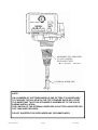
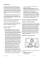
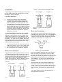
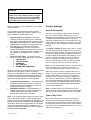
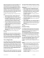
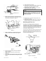
WATER SOFTENER
WITH MICROPROCESSOR
INSTALLATION & OPERATING
INSTRUCTIONS
Model :
Serial No :
AST1052TMP-960
………………………..
Manufacturer and Supplier of
FILTRATION & WATER TREATMENT PRODUCTS
for commercial, industrial and residential application
Telephone: (07) 3219 2233
Email: [email protected]
AST1052TMP-960
Page 1
Facsimile: (07) 3219 2266
Website: www.ibcwater.com.au
20/11/2006
CABINET STYLE MICROPROCESSOR
WATER SOFTENER
PERFORMANCE DATA SHEET
Automatic
Model No.
AS1052TMP960
Capacity & Salt
Dosage
Recommended
Maximum
Service Flow
Rate
Flow
LPM
Minimum
Maximum
gram/kg
gram/kg
Cont.
1820/3
3640/12
37
Pipe Size
Resin
Volume
Approx.
Shipping
Weight
(kg)
Space
Required
Inlet
Outlet
Drain
mm
mm
Litres
Per Kg
metres
25
12
52
70
0.70
0.60
1.58
Peak
52
WxDxH
Peak flow not recommended for extended periods of time.
Brine Tank:
Poly moulded construction complete with lid
Operating Pressure:
205 - 690 kPa
Temperature:
5o x 50oC
Electrical:
240V 50Hz 3 watts maximum
Mains transformer provided
WARNING
A pressure reduction valve should be installed in areas of high water pressure (above 690kPa)
A water hammer arrestor should be installed if water hammer prevails.
Caution:
Do not use where water is microbiologically unsafe or with water of unknown quality.
FAILURE TO OBSERVE WARNINGS WILL VOID WARRANTY
AST1052TMP-960
Page 2
20/11/2006
ASSEMBLE TOP STRAINER
TO VALVE BODY
PUSH AND TWIST
INTERNAL RISER PIPE
NOTE:
ON A NUMBER OF SOFTENER MODELS AND FILTERS IT IS NECESSARY
TO PACKAGE THE VALVE WITH THE TOP STRAINER SUPPLIED LOOSE.
IT IS IMPORTANT THAT THIS STRAINER IS ASSEMBLED TO THE VALVE
DURING INSTALLATION.
THE LENGTH OF THE INTERNAL RISER PIPE IS FACTORY ADJUSTED FOR
THE TANK SIZE PROVIDED.
DO NOT SHORTEN THIS PIPE UNDER ANY CIRCUMSTANCES
AST1052TMP-960
Page 3
20/11/2006
MODEL AST1052TMP-960 SOFTENER
THE MICROPROCESSOR CONTROL WILL REQUIRE BASIC DATA PROGRAMMING
TO SUIT THE WATER HARDNESS AND DESIRED UNIT CAPACITY
IMPORTANT: IT IS ESSENTIAL THAT YOU READ THE GENERAL CONDITIONER
INFORMATION AND CONTROL SETTINGS OF THIS MANUAL BEFORE ATTEMPTING
TO SET THE FUNCTIONS OF THIS UNIT. THE DEALER OR AGENT CAN SUPPLY THE
RECOMMENDED HARDNESS CAPACITY. HOWEVER DO NOT EXCEED THE
MAXIMUM KILOGRAMS OF HARDNESS CAPACITY FIGURE IN TABLE 2.
SUGGESTED SALT SETTINGS
Table 2
Kilograms of Hardness
Capacity
Minimum 1.82
2.5
3.0
Maximum 3.64
Kg of Salt
3.5
6
8.5
12
PROGRAMMING PARAMETERS
To be done at time of commissioning
Table 1
Parameter
Range of
Values
Min.
Increments
Programming
For your
Application
Units of
Measure
1:00 to 12:59
1
Current time
Hour/
minute
2:00am
Hour/
minute
Name
P1
Description
Time of day
AM or PM
P2
Time of day
Of
regeneration
1:00 to 12:59
AM to PM
1
P3
Hardness of
water
30 to 2500
1
10
Mg/l
P4
Salt amount
01 to 25.5
Kilograms
P5
Capacity of
unit
0.01 to 14.00
0.5
0.1
0.1
0.01
Kilograms
Notes
Range depends on value selected
for
P13. Enter the current time.
Range depends on value selected
for
P13. Skip this parameter to accept
the default or enter a new time.
Unit of measure depends on value
selected for P12. Test water
hardness and enter that value.
Refer table 2.
Factory set @ 12.5
Enter the unit capacity.
Factory set @ 3.8
NOTE: All other parameters have been factory preset - DO NOT CHANGE
AST1052TMP-960
Page 4
20/11/2006
INSTALLATION
OF
IBC TWO TANK WATER SOFTENER UNIT
FITTED WITH MODEL 255 VALVE/960 CONTROL
Check the equipment upon arrival for damage or shortages and report same to our Office or Agent before
starting.
Position the Softener and Brine Tank on a firm foundation, preferably concrete, with sufficient space for
operation and maintenance.
STEP 1
Make sure the softener tank is empty and clean. Remove brine tank lid and remove resin and
control valve.
STEP 2
Install the distributor tube in the softener tank, check the height in relation to top of softener
tank. (Approximately 25mm above the top of the tank).
STEP 3
Place a plastic cap over the end of the distributor pipe. A clean rag or plastic bag will suffice if
plastic cap is not available - NO media must enter distributor pipe.
STEP 4
Place a with mouth funnel in the mouth of the tank and load the resin and fill with water to
within 50mm of the top. The resin must not be allowed to be spilled on the floor as it is very
slippery and dangerous to walk on.
STEP 5
Clean top of neck and threads of all traces of resin. Remove the plastic cap fitted in Step 3
taking care not to raise the distributor pipe. NEVER shorten the length of the distributor pipe.
STEP 6
Unpack control valve, check that tank ‘O’ ring is in place. Screw in top strainer if not fitted. Fit
control valve to softener tank, screw down hand tight. Attach bypass valve if supplied and then
thread adaptor nuts and pipe piece with the sealing gasket.
STEP 7
Connect inlet, outlet pipes and drain line to control valve as per Instruction Booklet.
STEP 8
Remove lid from brine tank, connect brine tube from air check assembly on control valve, to
brine riser tube in brine tank. Then connect brine overflow drain line to waste trap.
STEP 9
Refer to Instruction booklet for start up procedure (page 23 "placing conditioner into Service")
STEP 10
Load two bags of 25kg high purity water softener salt into brine tank and replace lid.
STEP 11
To prevent the brine tank over flowing it will be necessary to maintain the salt level in the tank
to that of the initial fill and replenish the salt after two regenerations with one bag of salt.
Table 3
MODEL
RESIN LITRES
BRINE TANK - SALT
LOADING KG
52
50
AST1052TMP-960
AST1052TMP-960
Page 5
20/11/2006
255-960 MICROPROCESSOR
CONTROL
CONDENSED PROGRAMMING INSTRUCTION SHEET
Note:
For a full understanding of your water softener we advise that the instruction manual
provided with the softener should be fully read.
After the water softener has been fully installed with the correct amount of salt placed in the
brine cabinet or external brine tank it will be necessary to program into the 960
microprocessor, two functions to suit local conditions. It will be necessary to know the
‘hardness” of the water to be softened. If the water supply is from a municipal supply the
hardness can be obtained from the local “water authority”. If the water supply is from a bore
or non-municipal supply then the total hardness would be found from the water analysis
carried out when the softener was recommended.
•
The following will have to be programmed into the control
ð Current time of day
ð Hardness – of your local water supply
•
Plug transformer into main GPO.
•
Push lead end into socket underneath the front of the valve on left hand side corner
•
Check that the front dial camshaft position indicator (white line mark) is pointing to
“REGENERATION COMPLETE” position.
If not, turn power on at mains. The display will light up as “E r r 3” and the electric motor
will automatically drive the dial and cam around to the regeneration complete position.
What is now shown in the DISPLAY is an alternating “TIME OF DAY“ and “CAPACITY”
as indicated by a green light highlighting the relevant setting.
The clock function has been pre programmed as a 12 hour clock. Therefore if the
current time of day is in the morning, follow the instructions below:
IF THE CURRENT DAY IS ‘AM’
•
To set the “TIME OF DAY”
þ
Wait till the green light moves to the “TIME OF DAY” position
Immediately press “SET” button.
AST1052TMP-960
Page 6
20/11/2006
þ
The last digit will blink –
Using the ñò buttons, key in the current last minute figure.
Eg, AM 11.25 – Key in ‘5’
þ Press the ï button - the first minute digit will blink.
Using the ñò buttons, key in the current first minute figure.
In example 11.25 – Key in ‘2’
þ
Press the ï button – the second hour digit will blink.
Using the ñò buttons, key in the current second hour figure.
In example 11.25 – Key in ‘1’
þ
Press the ï key – the first hour digit will blink.
Using the ñò buttons, key in the first hour figure.
In example, 11.25 – Key in ‘1’
Now –
If the time is 10am or after, key in “1” and press the “SET” button.
If the time of day is before 10am, key in “0” and press the “SET” button.
If there is a DOT under "PM" then press either of the UP/DOWN button once to
remove the DOT and then press again to bring up the No. 1.
DO NOT FORGET TO PRESS "SET" TO LOCK IN THE TIME.
AST1052TMP-960
Page 7
20/11/2006
IF THE TIME IS “PM”
þ
Wait till the green light moves to the “TIME OF DAY” position
Immediately press “SET” button.
þ
The last digit will blink –
Using the ï button, key in the current last minute figure.
Eg, PM 03.25 – Key in ‘5’
þ Press the ï button - the first minute digit will blink.
Using the ñò buttons, key in the current first minute figure.
In example 03.25 – Key in ‘2’
þ
Press the ï button – the second hour digit will blink.
Using the ñò buttons, key in the current second hour figure.
In example 03.25 – Key in ‘3’
Press the ï button – the first hour digit will blink. Using the ñ button only keep on
pressing
slowly until a little dot appears in the top left hand corner of the display
þ
.
under ‘PM’ – if the display is blinking and shows ‘1’ keep on pressing ñ button until 0
appears, the press “SET” button.
Note: If the actual time is after 10 PM then the ñ button would not be further pressed
.
and the display left on 1.
Note: If when programming the figures in, the display reverts back to the green button
moving between “time of day” and “capacity”, it just means that you have taken too long
to program the settings in. Do not worry all you need to do is to press the “SET” button
when the green light is against the setting and start over inputting the figures in a bit
faster.
Make sure at the end of programming that the “set” button is pushed.
AST1052TMP-960
Page 8
20/11/2006
•
To input “HARDNESS”
Note: this program will only accept a figure rounded to the nearest “TEN”. Eg for a
hardness of say 183 the 190 will have to be programmed in the setting ie the next higher
“TEN” number will have to be selected.
þ
Wait till the green light moves to the “TIME OF DAY” then using the ò button keep
pressing till the green light moves down to “HARDNESS” then press “SET” button.
þ
The ten digit (second from the left) will blink, using the ñò buttons input the numeral
required eg. 190 hardness input 9
þ
Using the ï button select the next blinking digit and using the ñò buttons input the
numeral required, eg. 190 hardness input 1
þ
Using the ï button select the next blinking digit which normally should be zero ‘0’ for
most water harness if the display shows any other number other than zero then use
the ò button to bring it back to zero and then press “SET”.
The softener has now been programmed and can now go into service. However, it is
advisable to check the settings in the program, wait till the green light moves to “TIME OF
DAY”.
•
Check time of day is correct
•
Press ò button to “TIME OF REGENERATION” 2:00 should be displayed
•
Press ò button to “HARDNESS” the hardness figure that you put in should be displayed
•
Press ò button “SALT AMOUNT” take note of the figure displayed. Refer to table 2 in
the manual under “SUGGESTED SALT SETTING” the figure should correspond to the
bottom number in the right hand corner, under “KG OF SALT” heading.
•
Press the ò button to “CAPACITY” take note of the figure displayed again refer to table
2 and the displayed number should correspond to the number at the bottom number
under “KILGRAMS OF HARDNESS CAPACITY”.
Please note: When the display goes back to alternating the green light between “TIME OF
DAY” and “CAPACITY” that the capacity display NOW will be different to what has just been
checked, what is now displayed is the volume of water that the softener will pass in “CUBIC
METRES” before regenerating. However, when using the ñò buttons to check this setting
the microprocessor will display the “EXCHANGE HARNESS CAPACITY OF THE
SOFTENER” and this can be modified if required, see the manual for full details.
AST1052TMP-960
Page 9
20/11/2006
It is recommended that the softener be now given a regeneration so as to pre-clean
the resin bed. Before this is done proceed as follows:
•
Turn power off
•
Make sure inlet water to softener valve is “OFF”, outlet valve “OFF” and bypass open
•
Verify that drain line is fitted and that there is an “AIR GAP” between the drain pipe and
waste hole.
•
Remove “VALVE COVER” by pushing the tab, (at rear of the cover at the left hand back
corner) backwards
•
The valve camshaft is now evident
þ
Slowly turn the camshaft anti-clockwise so that the last two cams (at the far emd) are
just riding on the two narrow brass ends are now pushed over to the right hand side.
The valve is now in the “BACKWASH POSITION”
•
Slowly open the mains inlet valve. Do not open fully, just enough that air and water will
be discharged at the drain. When no more air is being expelled along with the water,
close off the mains water inlet valve.
•
Slowly turn the camshaft anti-clockwise till the white line in the round window comes
around to the “REFILL” position.
•
Turn on the “POWER”. The display will show ‘E r r 3” and the control will advance the
camshaft by itself around to the “REGENERATION COMPLETE” position (this may take
up to 5 minutes) and the “E r r 3” being displayed will then revert back to the “TIME OF
DAY”/”CAPACITY” green light alternating.
•
Once the display green light is alternating
þ
Pour 10-12 litres of water into the brine tank or cabinet. This is an initial amount of
water utilised for the first regeneration.
þ Open mains water inlet valve
þ
Press the large “REGENERATION” button and hold for approximately two seconds
þ
The green light will now be against “REGEN TIME REMAINING” which is the time
that the softener is in the regeneration mode and will decrease till the softener
completes the regeration. During this time the controls green light will alternate
between “TIME OF DAY” and “REGEN TIME REMAINING”.
AST1052TMP-960
Page 10
20/11/2006
The softener will regenerate and the window display will then be at the “REGENERATION
COMPLETE” position. During the process the brine tank or cabinet will be refilled with the
correct amount of water necessary to dissolve the salt required.
•
Open the outlet mains valve and close off the bypass valve and check the treated water
at a tap for “HARDNESS” using the Yes/No tablets provided. Note: run the water for a
few minutes to displace the initial untreated water remaining in the pipeline.
AST1052TMP-960
Page 11
20/11/2006
Series 255 Valve / 960 Control
Water Conditioning Control System
Installation, Operating and Maintenance Manual
AST1052TMP-960
Page 12
20/11/2006
Table of Contents
Page
Introduction ……………………………………………………………… 14
Special Features
General Conditioner Information …………………………………….. 14
How Your Conditioner Works
Model 960 Control Front Panel
Control Settings ..……………………………………………………….. 17
General Information
Time of Day Clock
Time of Regeneration
Hardness Setting
Salt Setting
Capacity Setting
Water Conditioner Regeneration ………………………………….…. 20
Automatic Regeneration
Manual Regeneration
Care of Your Water Conditioner ……………………………………… 20
General
Cleaning the Injector/Injector Screen
Maintaining the Drain Line
Manual Valve Operation ……………………………………………….. 22
Additional Features ………………………………………………….…. 22
Disinfection of Water Conditioners ………………………………..… 22
Replacement Parts …………………………………………………….... 24
Troubleshooting ………………………………………………….……… 28
Alarms
Troubleshooting Procedures
Specifications …………………………………………………….……… 30
Glossary of Terms …………………………………………………….…. 30
Safety
Caution
Warning
The plug-in transformer for this
equipment is rated for indoor use
only.
Never attempt o work on this control while
standing in or near water without
disconnecting electrical power to the
control.
AST1052TMP-960
Page 13
20/11/2006
Introduction
The Model 960 Control provides sophisticated,
demand-based water conditioning by incorporating a
microprocessor and a water meter to electronically
monitor the amount of water used daily. Each day, at
Time of Regeneration, the control determine if the
capacity remaining is sufficient to provide conditioned
Water for the next day. If the remaining capacity is
too small, the control automatically regenerates the
resin bed.
If water usage changes, the computer automatically
compensates for the change and regenerates as
needed. Regeneration based on actual water usage.
The control provides efficient, trouble-free, uninterrupted soft water luxury.
The Series 255 valve combines design simplicity with
glass reinforced NORYL* plastic construction to
provide an uncommonly reliable appliance.
If maintenance becomes necessary, the Model 960
Series 255 water Conditioner System offer a unique
"separation" capability for quick repairs.
NORYL is a trademark of GE Plastics.
Special Features
•
•
•
•
Memory Retention. During a power outage,
critical operating information in the control's
memory is stored in a special electronic device
called a NOVARAM. This information includes the
time of day, water usage amounts, daily average
water usage, all programming data and the
number of days since the last regeneration. When
power is restored, the information is re-turned to
the microprocessor and operation resumes as if
an outage never occurred. The time of day will be
late by the length of the power outage. Because
most power outages are less than one minute in
duration, it may be months or years before the
time display requires resetting. If an outage of one
or more hours occurs, the time of day should be
reset but no other reprogramming is necessary.
Design Reliability. Solid-state electronics assure
many years of trouble-free performance. The
metering system has only one moving part; a
rotating turbine that measures water usage.
Time and Capacity Display. During normal
conditioning operation, the correct time of day
alternates with capacity on the display. The
capacity value is the number of gallons (cubic
meters of metric units) of water that the unit can
condition before another regeneration is needed.
Flow indicator. The colon between the hours and
the minutes in the Time of Day display flashes to
indicate the flow of service water through the
AST1052TMP-960
Page 14
•
•
valve. This provides an easy determination of
proper meter operation.
Hardness and Capacity Settings. Once the
hardness and capacity settings are entered, the
information cannot be lost due to a power outage,
so reprogramming is not necessary.
Guest Cycle. An extra regeneration can be
achieved at any time by pressing the REGEN
button on the front panel. It takes a few minutes
for the regeneration to start. The unit completes
the regeneration in about two hours. This feature
is beneficial when you expect to use more than
the normal amount of water; for example, guest
visits or an extra heavy laundry day.
General Conditioner Information
How you're Conditioner Works
In general, your water conditioner works in the following manner. Hard water flows into the conditioner and
through the resin bed where calcium and magnesium
hardness minerals are exchange. The conditioned
water flows out of the resin bed into your plumbing
system. After a certain amount of hard water has
passed through the conditioner, the resin cannot
remove any more minerals. This resin state is called
exhaustion and indicates that the resin needs to be
regenerated. The regeneration process restores the
conditioner's ability to soften water. The control
monitors the amount of water that flows through the
conditioner and automatically calculates when to
regenerate the resin bed.
Model 960 Control Front Panel
Figure 1
The main components of the model 960 Control front
panel are:
• Regeneration Cycle indicator
• Green Indicator Lights
• Four-Digit Display
20/11/2006
•
•
•
Programming Push Buttons
REGEN Push Button
Direct acting system functions independently of
water pressure. No pistons or diaphragms that
require a minimum water pressure to operate
•
Five-cycle operation provides for downflow conditioned water, upflow backwash, downflow brining
and slow rinse, downflow fast rinse, and refill of
the brine tank.
Valve discs are held closed by water pressure
and are leak tight. Valve seats are in a vertical
position, which is the position least vulnerable to
plugging.
•
System operation cannot get out of phase or
sequence. The control always returns to a fixed
conditioned water position after regeneration.
•
Bypass water is automatically available during
regeneration.
Figure
1 - 1Control
Figure
- Control
Air Check
Figure 2 - Tank Adaptor
•
Bypass Valve (optional)
Brine Tube Fitting
Connection 1/4" NPT
Inlet Connection 1" NPT or BSPT
Drain Connection 1/2" NPT or BSPT
Outlet Connection 1" NPT or BSPT
Tank Tread 2-1/2" - 8 male NPSM
AST1052TMP-960
Page 15
20/11/2006
Figure 3 - Autotrol Series 156 Bypass Valve
Installation
All plumbing and electrical connections must conform
to local codes. Inspect the unit carefully for carrier
shortage or shipping damage.
Not In Bypass
In Bypass
Location Selection
•
•
•
Locate unit as close to a drain as possible
If supplementary water treating equipment is
required, make sure that adequate additional
space is available. Locate the brine tank in an
accessible place so that salt can easily be added.
Do not install any unit closer than 10ft (3m) of
piping between the outlet of the water conditioner
and the inlet of the water heater. Water heaters
can transmit heat back down the cold water pipe
into the control valve. Hot water can severely
damage the controller.
A 10ft (3m) total pipe run (including bends, elbows
etc) is a reasonable distance to prevent hot water
damage. A positive way to prevent hot water from
flowing from a heat source to the conditioner is to
install a check valve in the soft water piping from the
conditioner. If a check valve is installed, make sure
that the water-heating unit is equipped with a properly
rated temperature and pressure safety relief valve.
Always conform to local codes.
•
•
•
Figure 4 - Typical Globe Valve Bypass
System
Drain Line Connection
The ideal location for the unit is above and not more
than 20ft (6.1m) from the drain. For such installations,
using the appropriate adaptor fitting (not supplied),
connect 1/2 in (1.3cm) plastic tubing to the drain line
connection located at the rear of the control.
Do not locate the unit in an area where the temp
ever falls below 34ºF (1ºC) or over 120ºF (49ºC).
Do not install the unit near acid or acid fumes.
Do not expose the unit to petroleum products.
Figure 5 - Air Gap Installation
Water Line Connection
A bypass valve system must be installed to provide
for occasions when the water conditioner must is bypassed for hard water or for servicing. The most
common bypass systems are the Autotrol Series 156
Bypass Valve, Figure 3, and plumbed-in globe
valves, Figure 4. Though both are similar in function,
the Autotrol Bypass offers simplicity and ease of
operation.
Not In Bypass
If the unit is located more than 20ft (6.1m) from the
drain, use 3/4in (1.9cm) tubing for runs up to 40ft
(12.2m). You may elevate the line up to 6ft (1.8m)
providing the run does not exceed 15ft (4.6m) and the
water pressure at the conditioner is not less than
40psi (280kPa). You may elevate an additional 2ft
(61cm) for each additional 10psi (70kPa) of water
pressure.
When the drain line is elevated and empties into a
drain which is below the level of the control valve,
form a 7 inch (17cm) loop at the drain end of the line
so that the bottom of the loop is level with the drain
line connection. This provides an adequate siphon
trap.
In Bypass
If the drain empties into an overhead sewer line, a
sink-type trap must be used.
AST1052TMP-960
Page 16
20/11/2006
Caution
Never connect the drain line into a drain,
sewer line or trap. Always allow an air gap
between the drain line and the wastewater
to prevent the possibility of sewage being
back-siphoned into the conditioner.
Refer to Figure 1 or your conditioner for the location
of these features.
The front panel incorporates several important
features which allow you t know the status of your
water conditioner. These features are:
•
•
•
Regeneration Cycle Indicator. The white
indicator points to the status of the conditioner.
Soft water is available when the indicator points to
REGENERATION COMPLETE. Other positions
indicate that the conditioner is regenerating the
resin bed and only hard water is available.
Four-Digit Display. The four-digit red LED
display shows system information such as time of
day, gallons of conditioned water available, time
the conditioner will regenerate, or any error
alarms
Green indicator lights. The green indicator
lights are located at the right of the control panel.
Ο TIME OF DAY
Ο TIME OF REGEN
Ο HARDNESS
Ο SALT AMOUNT
Ο REGEN TIME REMAINING
When a green light is on next to one of the six control
legends, the LED display provides information
pertain-ing to that legend. When conditioned water is
available, the display alternates between TIME OF
DAY and CAPACITY and the corresponding green
lights alternate between these control legends.
•
•
Programmed Push Buttons. The programming
buttons are located at the bottom of the panel
under the display. Use the buttons to look at or
change the conditioner settings.
REGEN Push Button. The REGEN button is
located at the bottom of the panel below the six
indicator lights. Press the button to start a
regeneration of the water conditioner.
Note: If you press the button again a minute or more
after a regeneration begins, a second regeneration
will start when the first regeneration is completed. The
display freezes with the REGEN TIME REMAINING
information. After the first regeneration is completed,
the second regeneration begins immediately. The
display will alternate between the TIME OF DAY and
REGEN TIME REMAINING.
AST1052TMP-960
Page 17
Control Settings
General Information
Use the four programming push buttons to change
any of the control settings. Settings can only be
changed if the regeneration cycle indicator is pointing
at REGEN-ERATION COMPLETE. If you try to
change the setting when the cycle indicator is in any
other position or if the setting is not valid, the control
beeps to let you know that the new setting has been
ignored.
To change a setting: Press the down arrow ò button
until the green light is illuminated next to the control
setting you want to change. That control setting value
shows on the display. Press the SET button and the
far right number on the display starts flashing. If you
want to change the number, press the up arrow ñ
button to increase the number or the down arrow ò
button to decrease the number. To skip the number
without changing, press the left arrow ï button.
Note: If you press and hold either the up arrow ñ button or the down arrow ò button for more than 1
second, the flashing number will scroll up or down.
When the number is correct, press the left arrow ï
button. The first number stops flashing and the next
number starts flashing. You can only change the
flashing number. Continue changing numbers until
you reach the desired setting. Press the SET button.
The numbers stop flashing and the control accepts
the new setting. After approximately 30 seconds, the
control starts alternating the display between TIME
OF DAY and CAPACITY.
Note: If a beep sounds, the new setting is not accepted because it was outside the range of allowable
values. The old setting will be shown on the display.
Time of Day Clock
The Control uses the Time of Day Clock and the
amount of conditioned water remaining to decide
when to begin a regeneration. When a regeneration is
necessary and the Time of Day Clock is at the same
time as the Time of Regeneration setting, the control
starts the regeneration.
20/11/2006
When the green light is on next to the TIME OF DAY
legend, the display is showing the time that the
control thinks it is correct. If you need to change the
Time of Day, refer to the instructions later in this
section. The Time of Day displays time in hours and
minutes sepa-rated by a colon[:]. When the colon is
flashing on and off, water is flowing through the
conditioner. There is a small red dot in the upper left
corner near the PM letters to indicate PM for 12-hour
clocks. When the dot is off, the time is AM. You can
set the clock for any time, AM or PM.
Complete the following steps to change the Time of
Day:
1. Press the down arrow ò button until the green
light next to the TIME OF DAY legend is on.
2. Press the SET button and the minute number on
the display starts flashing. If you want to change
this number , press the up arrow ñ button to
increase the number or the down arrow ò button
to decrease the number. To skip the number
without changing, press the left arrow ï button.
3. When the number is correct, press the left arrow
ï button. The first number stops and the next
number starts flashing. You can only change the
flashing number.
4. Continue changing numbers until you reach the
desired setting.
5. Press the SET button. The number stops flashing
and the control accepts the new setting. After
approximately 30 seconds, the control starts alternating the display between TIME OF DAY and
CAPACITY.
Note: If a beep sounds, the new setting is not
accepted.
Reminder: The control does not keep time during a
power outage but will resume its timekeeping from the
time of day power was lost. A short power outage
should not cause a problem. If the outage is several
hours, the control will regenerate at the wrong time of
day. All other memory is stored in the NOVRAM and
maintained during power outage. Refer to page3.
Time of Regeneration
The control uses the Time of Regeneration to decide
when to begin a regeneration. When a regeneration is
necessary and the Time of Day Clock is at the same
time as the Time of Regeneration setting, the control
starts the regeneration. The factory setting for Time of
Regeneration is 2:00 AM. If this time is inconvenient,
you can select any other time of day. Remember that
the soft water is not available during a regeneration of
the water conditioner. Time of Regeneration can be
set for any time, AM or PM.
Note: The control may be programmed for an immediate regeneration option. In this case, the control does
not wait for the Time of Regeneration but regenerates
AST1052TMP-960
Page 18
when the remaining capacity reaches zero. Contact
your dealer for more information regarding this option.
Complete the following steps to change the Time of
Regeneration:
1. Press the down arrow òbutton until the green
light next to the TIME OF REGEN legend is on.
2. Press the SET button and the minute number on
the display starts flashing. If you want to change
this number, press the up ñ button to increase
the number or the down arrow ò button to
decrease the number.
To skip the number without changing, press the
left arrow ï button.
3. When the number is correct, press the left arrow
ï button. The first number stops flashing and the
next number starts flashing. You can only change
the flashing number.
4. Continue changing numbers until you reach the
desired setting.
5. Press the SET button. The number stops flashing
and the control accepts the new setting. After
approximately 30 seconds, the control starts alternating the display between TIME OF DAY and
CAPACITY.
Note: If a beep sounds, the new setting is not
accepted.
Hardness Setting
The Hardness Setting refers to the amount of hardness minerals in your water before it is conditioned.
The control uses this setting to calculate how many
gallons of water can be conditioned before a
regeneration is necessary.
Your water treatment dealer tested the water at the
time of installation and entered a Hardness Setting in
the control. We recommend that you consult your
dealer or have your water retested before changing
this setting
You can see the Hardness Setting the dealer entered
by pressing the down arrow ò button until the green
light next to the HARDNESS legend is on. The
number on the display is the measure of water
hardness in grains per gallon (milligrams per litre for
metric).
Complete the following steps to change the Hardness
Setting:
1. Press the down arrow òbutton until the green
light next to the HARDNESS legend is on. The
setting range is (30 TO 2500 milligrams/litre for
metric)
2. Press the SET button and the minute number on
the display starts flashing. If you want to change
this number, press the up ñ button to increase
the number or the down arrow ò button to
decrease the number.
To skip the number without changing, press the
left arrow ï button.
20/11/2006
3. When the number is correct, press the left arrow
ï button. The first number stops flashing and the
next number starts flashing. You can only change
the flashing number.
4. Continue changing numbers until you reach the
desired setting.
5. Press the SET button. The number stops flashing
and the control accepts the new setting. After
approximately 30 seconds, the control starts alternating the display between TIME OF DAY and
CAPACITY.
Note: If a beep sounds, the new setting is not
accepted.
Reminder: Whenever the HARDNESS or CAPACITY
• Setting is changed, you should regenerate the
conditioner by pressing the REGEN button.
AST1052TMP-960
Page 19
20/11/2006
Salt Setting
Capacity Setting
The Salt Setting refers to the total amount of salt, in
pounds, that the control uses during a regeneration of
the resin bed. The amount of salt used in a regeneration determines the amount of water that the conditioner softens between regenerations. If this setting is
changed, it may be necessary to change the Capacity
Setting as well. Refer to Table2 for SALT and
CAPAC-ITY information.
Complete the following steps to change the Hardness
Setting:
1. Press the down arrow òbutton until the green
light next to the SALT legend is on. The display
shows a number with a zero or a five to the right
of the decimal point. No other number can be
entered in this position. The setting range is (0.1
to 25.5 kilograms for metric).
2. Press the SET button and the minute number on
the display starts flashing. If you want to change
this number, press the up ñ button to increase
the number or the down arrow ò button to
decrease the number.
To skip the number without changing, press the
left arrow ï button.
3. When the number is correct, press the left arrow
ï button. The first number stops flashing and the
next number starts flashing. You can only change
the flashing number.
4. Continue changing numbers until you reach the
desired setting.
5. Press the SET button. The number stops flashing
and the control accepts the new setting. After
approximately 30 seconds, the control starts alternating the display between TIME OF DAY and
CAPACITY.
Note: If a beep sounds, the new setting is not
accepted.
If the control does not display this setting, your dealer
has disabled it. Some municipalities require that the
Salt Setting not be adjustable. Contact your dealer for
additional information.
AST1052TMP-960
Page 20
The Capacity Setting refers to the kilograins of hardness that can be removed by the conditioner between
regenerations. Your dealer entered this setting when
the control was installed. Please consult with your
dealer before changing this setting.
Complete the following steps to change the Hardness
Setting, refer to Table 1:
1. Press the down arrow òbutton until the green
light next to the SALT legend is on. The setting
range is (0.1 to 14.00 kilograms for metric).
2. Press the SET button and the minute number on
the display starts flashing. If you want to change
this number, press the up ñ button to increase
the number or the down arrow ò button to
decrease the number.
To skip the number without changing, press the
left arrow ï button.
3. When the number is correct, press the left arrow
ï button. The first number stops flashing and the
next number starts flashing. You can only change
the flashing number.
4. Continue changing numbers until you reach the
desired setting.
5. Press the SET button. The number stops flashing
and the control accepts the new setting. After
approximately 30 seconds, the control starts alternating the display between TIME OF DAY and
CAPACITY.
Note: If a beep sounds, the new setting is not
accepted.
Reminder: Whenever the HARDNESS or CAPACITY
setting is changed, you should regenerate the conditioner by pressing the REGEN button.
If the control does not display the Capacity Setting,
your dealer has disabled it. Some municipalities
require that the Salt Setting be disabled which also
disables the Capacity Setting. Contact your dealer for
additional information.
20/11/2006
Conditioner Regeneration
Manual Regeneration
Your water conditioner regenerates for one of two
reasons:
• The control determines that the conditioner does
not have enough capacity remaining to satisfy
your soft water needs for the next day.
• The REGEN button was pressed.
To force the control to perform a regeneration, press
the REGEN push button. This button is located on the
front of the control. When you press the REGEN
button, the control performs a full regeneration of the
conditioner. You can use this feature if you need a
large amount of conditioned water but the capacity
remaining is low.
In either case, the REGENERATION INDICATOR
makes one complete counterclockwise rotation and
returns to REGENERATION COMPLETE. The
indicator pauses at some or all of the different
positions shown on the label around the indicator. The
display alternates between TIME OF DAY and
REGEN TIME REMAINING, as indicated by the green
lights next to the legends. Regen Time Remaining is
shown in minutes on the display. When the indicator
reaches REGENERATION COMPLETE and the time
remaining is zero; the regeneration is complete,
conditioned water is available for use, and the control
starts alternating the display between TIME OF DAY
and CAPACITY. No settings can be changed
during a regeneration. The settings can be viewed,
but the control beeps and ignores any attempt to
change settings.
Automatic Regeneration
The control makes regeneration decisions based on
the amount of water that has flowed through the
condi-tioner. The control uses the Hardness and
Capacity settings to calculate the number of gallons
(cubic meters for metric) which can be conditioned. At
the Time of Regeneration, the control updates the
average usage for the previous day and adjusts the
reserve capacity accordingly. The reserve is kept at a
minimum for optimal economy. The control reacts to
a sudden increase in water usage. If a day's is more
than double the current average, the control
anticipates that a second day of high usage is likely to
occur. The high usage amount is used as the reserve
when the control performs the regeneration
computation.
The Guest Cycle option and the Calendar Override
option may override this computation. Refer to the
Additional Features section in this manual or contact
your dealer for more information about these options.
The factory setting for Time of Regeneration is 2:00
AM. You can change this time. Refer to the Time of
Regeneration section in this manual for additional
information.
AST1052TMP-960
Page 21
Note: If you press this button again a minute or more
after regeneration begins, a second regeneration will
start when the first regeneration is complete. The
display shows the REGEN TIME REMAINING
information.
Care of Your Water Conditioner
General
Check the salt level in the salt storage tank a few
weeks after installation and weekly after that. Always
maintain the salt level above the water level for a
consistent salt dosage and proper water conditioner
operation. Don't allow the conditioner to run out of salt
before refilling. When refilled, the salt storage tank
contains enough salt to support numerous resin bed
regenerations. Use pellet, block, or nugget water
conditioner salt. Do not use rock salt. Some rock salt
may contain high levels of impurities, which affect
conditioner operation. Have the salt storage tank
serviced once a year to remove accumulated
sediment that may impede brine draw.
Cleaning the Injector/Injector Screen
The injector is the component, which creates the
vacuum necessary to draw the brine into the water
conditioner. Clean the injector and the injector screen
once a year in order to maintain proper water
conditioning. Some locations may require more
frequent injector and screen servicing.
Complete the following steps to clean the injector and
the injector screen:
1. Unplug the wall mount transformer.
2. Shut off the water supply or put the bypass
valve(s) into the bypass position.
3. Remove the rear cover by pushing back the tab
provided on the cover, Next, lift the rear cover off
the valve, Figure 2.
20/11/2006
9. Clean and flush the injector.
10. Lubricate the o-rings on the injector, injector cap,
and injector screen with silicone lubricant
(Autotrol part number 156A59).
11. Reinstall the injector, injector cap and injector
screen (refer to the caution note).
Caution
Do not overtighten the plastic cap. Seat the cap
lightly into position. Overtightening can cause
breakage of the plastic cap, which may not be
evident immediately.
Figure 2
4. Relieve system pressure by opening the Fast
Rinse Drain Valve (the fifth valve back from the
control) with a screwdriver, Figure 3.
12. Reinstall cover, reconnect electric power, and
reset the time of day.
13. Slowly open the water supply valve or return the
bypass valve(s) to the "not in bypass" position.
Maintaining the Drain Line
The drain line discharges and brine during the
regeneration cycle. Typically, the line drains into your
floor drain or laundry tube. The installer should plumb
the drain line according to local codes, leaving a one
or two inch air gap between the end of the drain line
and the drain opening. Figure 5.
Figure 3
5. Using a screwdriver, unscrew and remove the
injector screen and the injector cap, Figure 4.
Be sure that the drain line remains unrestricted so the
regeneration water and brine can flow freely to the
drain. Do not set objects on the drain line that could
crimp the line and restrict flow.
Figure 5
Figure 4
6. Clean the screen with a fine brush. Flush with
water until clean
7. Using a needle-nose pliers, pull the injector
straight out.
8. Flush water into the injector screen recess of the
valve body to flush debris out through the injector
recess.
AST1052TMP-960
Page 22
Figure 7 - Air Check
20/11/2006
occur first. This feature is not set at the factory; your
dealer can set it at 1 to 30days.
Manual Valve Operation
The camshaft may rotate manually to actuate the
valve functions for service purposes.
1. Unplug the wall-mounted transformer.
2. Remove the rear cover by pulling back on the tab
provided on the cover. Next, lift the rear cover off
the valve, Figure 2.
3. Rotate the camshaft COUNTERCLOCKWISE
until the appropriate valve is opened by the
camshaft lobe. Use the regeneration cycle
indicator as a guide to which valve discs are
open.
4. When the service is complete, rotate the
camshaft so the regeneration cycle indicator is
pointing to the end of the refill cycle.
5. Reinstall cover, reconnect electric power, and
reset the time of day.
6. The display will shoe Err3 and the motor will start
up. After approximately 5 minutes, the indicator
will point to REGENERATION COMPLETE and
the control starts alternating the display between
TIME OF DAY and CAPACITY.
7. The conditioner is now in operation.
Additional Features
When your dealer installs the conditioner, the control
settings are adjusted to meet your soft water needs.
However, there are additional features which your
dealer can incorporate into the control. These
features are: 12 or 24-Hour Clock, Metric Units of
Measure, Calendar Override and Immediate
Regeneration.
12 or 24-Hour Clock
The standard clock is a 12-hour with a PM indicator.
An optional 24-hour clock without a PM indicator is
available. Time can be set from 00:00 to 23:59. This
option applies to both the Time of Day and Time of
Regeneration settings.
Metric Units of measure
The standard units of measure are U.S. values. Hardness is in grains per gallon, Salt in pounds, and
Capacity is in kilograins. The metric option changes
these to milligrams per litre, kilograms, and Kilograms
respectively. All controls settings use the metric
values when the metric option is selected.
Calendar Override
The Calendar Override option is a method of forcing
the control to regenerate after a preset number of
days, is normal demand-based regeneration does not
AST1052TMP-960
Page 23
Immediate Regeneration
The control is factory set to wait until the Time of Day
reaches the Time of Regeneration to begin a regeneration. Your dealer can program the controller to
regenerate any time the capacity remaining reaches
zero. Remember that you do not have soft water
available during any regeneration.
Disinfection of Water Conditioners
The construction materials of the water conditioner
system do not support bacterial growth or
contaminated the water supply. However, we
recommend that the conditioners be disinfected after
installation and before the conditioners are used to
treat potable water. In addition, a conditioner can
become fouled with organic matter during normal
usage or with bacteria from the water supply. Periodic
disinfection is recommended for all conditioners.
Use one of the following methods of disinfection
based on operating conditions, style of conditioner,
type of ion exchange, and disinfectant available.
Sodium Hypochlorite
Sodium Hypochlorite, 5.25% solutions, can be used
with polystyrene resin, synthetic gel zeolite,
greensand, and bentonites and are available under
trade names such as Chlorox, Linco, Bo Peep, White
Sail and Eagle Brand Bleach. Adjust the dosage if
stronger commercial solutions are used.
The recommended dosage for 5.25% solution is:
• Polystyrene resin: 1.2 fluid ounces per cubic foot.
• Non-resinous exchangers: 0.8 fluid ounces per
cubic foot.
Calcium Hypochlorite
Calcium Hypochlorite, 70% available chlorine, is
available in several forms including tablets and
granules. These solid materials can be used directly
without dissolving before application. The recommended dosage for Calcium Hypochlorite is two
grains (approx. 0.1 ounce) per cubic foot.
Complete the following steps to disinfect the
conditioner:
1. Add the Calcium Hypochlorite to the brine well of
the brine tank. Make sure that he brine tank has
20/11/2006
water in it so the solution is carried into the
conditioner.
2. Press the REGEN button.
Placing Conditioner into Operation
Initial Start-Up
Note: The above instructions reflect standard
commercial practices. Local codes may require
different installation procedures.
Brine Line Connection
Install an appropriate fitting onto the 1/4-inch male
NPT connection on the air check, Figure 7, and install
a length of flexible tubing between the air check fitting
and the brine pick-up tube at the brine tank.
Note: Make sure that all fittings and connections are
tight so that premature checking does not take place.
Premature checking occurs when the ball in the air
check falls to the bottom before all brine is drawn out
of the brine tank. Refer to the Troubleshooting
section in this manual for additional information.
Brine Tank Overflow Line Connection
In the event of a malfunction, the tank overflow
connection directs overflow to the drain instead of
spilling on the floor where it could cause water
damage. Complete the following steps to connect the
overflow fitting to the brine tank:
1. Locate the fitting hole on the side of the brine
tank.
2. Insert the overflow fitting (not supplied) into the
tank and tighten with the plastic thumbnut and
gasket as illustrated in Figure 6.
3. Attache a length of 1/2in (1.3cm) tubing (not
supplied) to the fitting and run to the drain.
Note: Don not elevate the overflow line higher than
3in (7.6cm) below the bottom of the overflow fitting.
Do not tie into the drain line of the control unit. The
overflow line must be a direct, separate line from the
overflow fitting to the drain, sewer or tube. Allow an
air gap as in the drain line connection, Figure 5.
Figure 6 - Overflow Line Connection
AST1052TMP-960
Page 24
After the water conditioning system is physically
installed, we recommend that the conditioner be
disinfected before it is used to treat potable water.
Refer to the Disinfection of Water Conditioners
section in this manual. Complete the following steps
to place the conditioner into operation:
1. Remove the rear valve cover by pulling back on
the tab located on the lower rear edge of the
cover. Next, lift the cover off the valve.
2. Grasp the camshaft and rotate COUNTERCLOCKWISE (As viewed from the front of the
control) until the indicator on the regeneration
cycle indicator points directly to the word
BACKWASH.
3. Fill the mineral tank with water Turning the water
supply off and place the bypass valve(s) into the
"not in bypass" position. Open the water supply
valve very slowly to approximately the 1/4 open
position.
Caution
If the water supply valve is opened too rapidly
or too far, resin may be lost. In the BACKWASH
position, you should hear air escaping slowly
from the drain line.
4. When all the air is purged from the tank (water
begins to flow steadily from the drain), slowly
open the main supply valve all the way. Allow the
water to run into the drain until the water appears
clear. Turn off the water supply and wait for about
five minutes to allow all trapped air to escape
from the tank.
5. Add water to the brine tank (initial fill). With a
bucket or hose, add approximately 4 gallons (15
litres) of water to the brine tank.
Open the water supply valve slowly to the full open
position. Carefully rotate the camshaft COUNTERCLOCKWISE until the indicator on the regeneration
cycle indicator points directly to the centre of the
REFILL position and hold there until the air check
(Figure 7) fills with water and water flows through the
brine line into the brine tank. Do not run for more than
two minutes. Rotate the camshaft COUNTERCLOCKWISE until the indicator points to the centre of the
BRINE/SLOW RINSE position.
Check the water is being drawn from the brine tank.
The water level in the brine tank will recede very
slowly. Observe the water level for at least three
minutes. If the water level does not recede, if it goes
20/11/2006
up, or if air enters the air check sight glass and the
ball falls and seats, refer to the Troubleshooting
section in this manual.
When the water is being drawn fro the brine tank,
rotate the camshaft COUNTERCLOCKWISE until the
indicator points to REGEN COMPLETE. Run water
from a nearby faucet until the water is clear and soft.
Replacement Parts
Valve Body and Tank Adaptor Module
AST1052TMP-960
Page 25
20/11/2006
Valve Body and Tank Adapter Module
Code
Part No. Description
1
1000238 Valve Assy. w/o Flow Controls 1
2
1000824 Camshaft, Std, One-Piece
1
3
1000827 Valve Cover, Black
1
4
Brine Refill Flow Control Assy. :
1000221 .14 GPM
1000223 .40 GPM
1
5
1000226 Screen/Cap Assy. With O-ring
1
6
Drain Control Assy. With
O-rings:
No. 6 for 6 in Diameter Tank
No. 7 for 7 in Diameter Tank
No. 8 for 8 in Diameter Tank
No. 9 for 9 in Diameter Tank
No. 10 for 10 in Diameter Tank
No. 12 for 12 in Diameter Tank
No. 13 for 13 in Diameter Tank
No. 14 for 14 in Diameter Tank
1
1034162
1000209
1000210
1000211
1000212
1000213
1000214
1000215
Qty
Code
Part No. Description
Qty
10
1033784 Tank Adaptor Assy.
1
11
1010429 O-ring, 3-1/8x3-1/2x3/16 BN
1
12
1010428 O-ring, 3/4x1x1/8 EP
1
13
1031402 Locking Bar:
English Language
1
14
1006093 Screw, No. 8x9/16 in 1
15
1001580 Spring, Valve Discs
9
7
1030502 Ball, Flow Control
1
16
Kits:
1033066 New to Old Air Check Adaptor
8
Injector Assy. With O-rings
1032970 "A" Injector - White
1032971 "B" Injector - Blue
1032972 "C" Injector - Red
1
17
1032416 Air Check Ass.
18
1001404 O-ring Group: Tank Adaptor
19
1040459 O-ring Group: Piping Boss
Injector Cap With O-rings
1000217 "A" Cap
1000218 "B" Cap
1000219 "C" Cap
1
20
1041010 Optional Riser Insert 13/16
*
1000250 Valve Discs Replacement
(*Not Shown)
9
1
* Not Shown
AST1052TMP-960
Page 26
20/11/2006
Meter Adapter Bypass Valve and Piping Boss
C
Bypass Valve
960 Control
AST1052TMP-960
Page 27
20/11/2006
3
* Not Shown
Meter Adapter Bypass Valve and Piping Boss
Code
Part No. Description
Qty
Part No. Description
Qty
Piping Boss
Bypass Valve
1
1040769 Bypass Body Assy
2
1040524 Installation Kit:
*
Code
1
1
Kit Piping Boss (Includes Hardware):
1
1000083 3/4 in NPT, Brass
1000084 1 in NPT, Brass
Plumbing Adapters
1000085 3/4 in BSPT
1001606 3/4 in Copper Tube Adaptor Kit 1
1001670 1 in Copper Tube Adaptor Kit
1
1001608 22mm Copper Tube Adaptor Kit
1
1000086 1 in BSPT
1031981 3/4 in NPT, Noryl
1031423 1 in NPT, Noryl
1001609 28mmCopper Tube Adaptor Kit 1
1001613 3/4 in CPVC Tube Adaptor Kit
1
1001614 1 in CPVC Tube Adaptor Kit
1
1001615 25mm CPVC Tube Adaptor Kit 1
1031982 3/4 in BSPT, Noryl
1030580 1 in NPT, Noryl
2
1040339 Piping Boss Installation Kit
*
1001408 Elbow Adapter
Meter Adapter
1001769 3/4 in NPT Plastics Pipe Kit
1
1001603 1 in NPT Plastics Pipe Kit
1
1001604 3/4 in BSPT Plastic Pipe Adaptor Kit
1
1001605 1 in BSPT Plastic Pipe Adaptor Kit
1
1001611 3/4 in BSPT Brass Pipe Adaptor Kit
1
1001610 1 in NPT Brass Pipe Adaptor Kit
1
1001612 1 in BSPT Brass Pipe Adaptor Kit
1
1
1032350 Kit, Meter Adapter
1
2
1032351 Installation Kit-Meter Adapter
1
3
960 or960B Electronic timer
1
4
Wall-Mount Transformer
1
1000810 100V Japanese Plug
1000811 120V North American Plug
1000812 220V Australian Plug
1000813 220V British Plug
1000814 220V European Plug
AST1052TMP-960
Page 28
20/11/2006
Troubleshooting
Your water conditioning system is designed and
manufactured for efficient, low maintenance service.
However, if problems do occur, this section provides
a list of possible causes and solutions
Refer to table 3 to help identify the cause of a problem. You can solve some problems yourself, such as
low salt in the storage tank or a blown household
fuse. However, some problems require installer or
dealer assistance.
Alarms
The control continuously monitors itself and sounds
an alarm if it detects something wrong. The alarm is a
beep that is on for one second and then off for nine
seconds. When the alarm sounds, the display shows
the letter Err with a number from 1 to 4. Table 2 lists
Err numbers, and solutions. To silence the alarm,
press any button on the control. If the error still exists,
the control will go back to the alarm condition after 30
seconds.
Caution
Service procedures that require the water
pressure to be removed from the system are
marked with a ! after the possible cause. To
remove water pressure from the system, put the
bypass valve or three-valve bypass into the
bypass position and open the Rinse Drain
Valve (the fifth valve back from the control) with
a screwdriver, Figure 3. Restore system water
pressure when the service work is completed.
Table 2 - Alarms
Indication
Description
Cause
Solution
Err1
Electronic Failure.
Control settings need
reprogramming.
Contact dealer.
Err2
Improper start of regeneration
(limit switch closed when it
should be open).
Faulty motor, circuit
board
or switch.
Valve camshaft has been
manually rotated during a
regeneration.
Attempt a manual regeneration. if
error persists, contact dealer.
Err3
Improper finish of regeneration
(limit switch open when it
should be closed).
Err4
Improper control settings.
Contact dealer.
Faulty motor, circuit
board
or switch.
Valve camshaft has been
manually rotated out of
the "regeneration
complete position.
One or more settings out
of the allowable range.
AST1052TMP-960
Page 29
Control will turn the motor on a
drive camshaft back to proper
location.
Hardness: Adjust range: 3 to 250.
Capacity: Adjust range: 0.1 to
140.0
Others: Contact dealer.
20/11/2006
Table 3 - Troubleshooting Procedures
Problem
Cause
Solution
1. Hard water at the tap.
a. Low or no salt in the salt storage
tank.
a. Refill the salt storage tank and manually
initiate a regeneration. Refer to the
Manual Regeneration section in this
manual.
b. Change the salt setting. Refer to the Salt
Setting section in this manual.
c. Check power.
d. Clean injector and screen. Refer to the
Cleaning the Injector/Injector Screen
in this manual. Briefly put control into
brine refill status. Refer to the Manual
Valve Operation section in this manual.
e. Replace or repair air check if needed.
Check brine line connections.
b. Salt setting to low to accommodate
water hardness or water usage.
c. Unit did not regenerate.
d. Plugged injector. !
e. Air check valve prematurely closed.
2. Hard water leakage
during service.
a. Improper Regeneration.
b. Leaking of bypass valve. !
c. O-ring around riser tube damaged. !
a. Check that the correct salt dosage is
used. Repeat regeneration.
b. Contact dealer.
c. Contact dealer.
3. Loss of power to the
system.
a. Transformer unplugged.
b. Fuse blown, circuit breaker open, or
circuit switched off.
a. Connect the power.
b. Correct the electrical problem.
4. Control does not
regenerate
automatically.
a. Transformer unplugged.
a. Plug transformer into outlet; plug transformer cable into control.
b. Contact dealer.
5. Control regenerates at
the wrong time of day.
a. Clock set incorrectly.
a. Reset clock. Refer to the Time of Day
b. Clock/Time of regeneration sections in
this manual.
6. Control does not draw
brine.
a. Low water pressure
b. Restricted drain line.
c. Injector or injector screen plugged. !
a. Increase water pressure.
b. Remove restriction.
c. Clean injector and screen, Refer to the
Cleaning the Injector/Injector Screen
section in this manual.
d. Replace injector. Contact dealer.
e. Manually operate valve stem to flush out
foreign matter holding disc open. Briefly
put control into brine refill status. Refer
to the Manual Valve Operation section
in this manual.
f. Replace or repair air check if needed.
Check brine line20/11/2006
connections.
b. Defective control.
d. Injector defective. !
e. Valve disc 2 and/or 3 not closed.
f.
AST1052TMP-960
7. Intermittent or irregular
Air check prematurely closed.
Page 30
a. Low water pressure.
a. Increase water pressure.
9. System using more or
less salt than salt control
Is set for.
9. Control backwashes at
excessively low or high
rate.
10. Flowing or dripping water
At drain line after
regeneration.
a. Inaccurate setting.
a. a. Make correct setting. Refer to the salt
Setting section in this manual.
A flow of water through the resin bed which propels
any remaining brine solution out of the resin tank to
the drain.
a. Incorrect backwash controller.
a. Contact dealer.
b. Foreign matter affecting controller b. Remove backwash controller.
Clean and replace.
operation. !
a. Drain valve (5 or 6) held open by
foreign matter.
b. Weak valve stem return spring.
a. Manually operate valve stem to flush out
foreign matter holding open disc.
Contact dealer.
b. Contact dealer.
SPECIFICATIONS
Voltage
102 to 132 VAC, 60 Hz
Current
50 mA
Operating Temperature
34 to 120ºF (1 to 49ºC)
Humidity
10 to 100% condensing allowed
Water Meter Accuracy
0.5 to 23 gpm
Note: Wall mounted transformer is rated for indoor use only.
Glossary of Terms
Alarms
Alarms are beeps, which alert you to operating conditions requiring attention. The beeps are on for one
second and off for nine seconds. The display shows
the type of error. Refer to the Alarms section in this
manual for additional information.
Backwash
An upward flow of water, which expands the resin,
bed to remove foreign particles.
Hardness
A common quality of water containing dissolved
calcium, magnesium and other elements. Water
hardness is usually expressed in grains per gallon or
milligrams per litre as calcium carbonate equivalent
Manual Regeneration (Guest Cycle)
Forces the control to regenerate by pressing the
REGEN button.
Brine
The salt solution which regenerates the conditioner's
resin bed
Regeneration
The process of drawing the brine solution from the
salt storage tank into the resin tank.
Includes the backwash, brine draw, and fresh water
rinse steps necessary to prepare the resin bed for
conditioning after exhaustion. Abbreviated as
"REGEN" in this manual.
Calendar Override Regeneration
Regeneration Indicator
If a normal demand-based regeneration does not
occur, the Model 960 Control regenerates the system
after a preset number of days. Your dealer can set
this feature at 1 to 30 days.
The mechanical component which indicates the
regeneration cycle status.
Fast Rinse (Purge)
The supply of synthetic organic exchange material
used in water conditioners.
Brine Draw
AST1052TMP-960
Page 31
Resin Bed
20/11/2006
AST1052TMP-960
Page 32
20/11/2006
HARDNESS TEST
1.
Water to be tested should be taken from a tap after the water softener
2.
Measure 10ml of water into plastic bottle supplied (approximately 1/3 full)
3.
Add one Yes/No tablet to sample water, replace cap and shake until tablet has
completely dissolved.
(NOTE: do not handle Yes/No tablet with fingers)
4.
The final colour to be obtained for soft water is green. (Note: The shade of
green may vary.) If the colour turns red, the water is above 20 mg/l hardness,
therefore another regeneration is recommended.
5.
Rinse plastic bottle after each test has been completed.
6.
When used as above, the tablets change the colour from green to red at a
hardness of approximately 20ppm based on a sample volume of 10mls.
Other hardness test kits are available for more accurate testing eg.
Hardness Tablets
Directions:
Take a 50ml sample of water in a screw capped bottle. Add one (1)
tablet to sample, shake or crush to disintegrate. Repeat until last trace
of reddish tinge disappears. The final colour is usually blue but with
some water a greyish coloured end point is obtained.
Using 50ml sample Hardness ppm = (number of tablets x 40) - 20
LR (BW) Tablets
Directions:
Take a 100ml sample of water in a screw capped bottle. Add one (1)
tablet to sample, shake or crush to disintegrate. Repeat until last trace
of reddish tinge disappears. The final colour is usually blue but with
some water a greyish coloured end point is obtained.
Using 100ml sample Hardness ppm = (number tablets x 2) – 1
Contact IBC Water if further details are required.
AST1052TMP-960
Page 33
20/11/2006