1
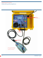
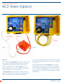
Operating Instructions
RCD Tester (Option)
Operation
Select the appropriate RCD test option from the Other
Appliance menu; use the F1 and F2 keys to scroll up and
down the list of options.
Portable RCDs (10 or 30mA)
Start the selected portable RCD test by pressing the “Start”
button. A message on the LCD display will then instruct
you to:
1Connect the portable RCD between the “Standard 240V
Test Plug” and “Leakage Test Socket” on the front panel
of the STC.
2Press "Start" to initiate the test. The Pro Logger II
will then perform an "Electrical Test" (Polarity, Insulation
& Earth).
3The Pro Logger II will then display "Arm RCD then hit
Start". At this point, arm the RCD and press "Start" to
perform the RCD trip time test.
4 After the RCD trips, the trip time will be displayed in
milliseconds together with a “Pass” or “Fail” message.
To ensure the RCD has been tested on both raising and falling
edges of the mains cycle, the Pro Logger II will then prompt
you to perform a 180° test by resetting the RCD and pressing
“Start” (this test is optional). After the RCD trips, the trip time
will be displayed in milliseconds together with a “Pass” or
“Fail” message.
Note: Pressing "Reset" after each RCD time test
will move you quickly to the next screen.
Fixed RCDs (10 or 30mA)
The Pro Logger II will then prompt you to perform a 180°
test by resetting the RCD and then pressing “Start” (this is
an optional test, ensuring the RCD has been tested on both
raising and falling edges of the mains cycle). After the RCD
trips, the trip time will be displayed in milliseconds together
with a “Pass” or “Fail” message. In earlier models the screen
will be active for 2 minutes to enable you to record the time.
WARNING
1When the Pro Logger II is in the RCD test mode,
240VAC is present on the front panel Test Socket
2Do not connect an appliance to a Portable RCD
under test
3When testing a Portable RCD do not use the
front panel “IEC 240V Test Plug”. Only use the
“Standard 240V Test Plug”
4Care should be taken when tripping any Fixed
RCD (causing a sudden loss of mains power) that
other equipment, reliant on power from that
circuit, will not be damaged.
Note 1: RCD Trip Time Threshold (Portable 30mA RCD
Test function) When testing Portable RCDs the trip current
is suddenly applied and the trip time measured. In the case
of 30mA Portable RCDs the acceptable trip time is ≤300mS
however at 150mS (a threshold considered good practice
AS37060:2010) the Pro Logger will fail the RCD in Firmware
below Firmware Version V4.46; for V4.46 and above the
Pro Logger will provide the user with a warning (not a fail)
if the Trip Time is ≥150mS but ≤300mS.
A Fixed RCD refers to an RCD in the mains power circuit
supplying the Pro Logger II.
Note 2: In some cases a previously tested and safe extension
lead may be required to connect the Standard 240V Test
Plug and the female socket of the RCD under test.
Start the selected Fixed RCD test by pressing the “Start”
button. A warning will be displayed stating “Power will fail
during this test”.
Note 3: If Data Logging is switched on then additional
information will be requested. See section entitled ”Data
Logging”
Press the “Start” button again to initiate the test. After
the RCD trips, the trip time will be displayed in milliseconds
together with a “Pass” or “Fail” message. The Pro Logger II
will provide power to the display while the RCD is reset and
mains power is returned.
23
SafeTcheck Pro Logger II