1
For Concealed Wiring
1.
2.
3.
4.
5.
6.
7.
8.
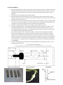
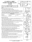
Mount the two legs that do not have holes at the curved end onto the rail first. To do this remove the
mounting bracket from the leg by loosening the grub screw using the allen key provided. Then screw
through the centre of the leg into the rail at the non powered end using the two machine screws
provided.
Now select which side wiring you require (left or right).
Mount the third leg with the mounting bracket in it onto the side of the rail that will not have the
wiring and secure it to the rail using the screws already mounted on the rail. Do the same with the leg
that will have the wire through it.
Hold the rail in position and mark the wall where the legs will be and then hold the mounting brackets
in the centre of this and drill holes for your anchor which will vary depending on the wall type you are
screwing into. For ease of drilling hard tiles we recommend using Thermodrill..
Screw the 3 mounting brackets to the wall making sure they are tight and secure.
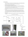
Feed the lead supplied with the rail through the white plastic grommet with the connection end on
the large end of the grommet. Then connect the lead to the rail lead making sure you line it up
correctly and tighten the connection. The 4th leg slides over the cable and connection and secures to
the rail with the screw already attached to the rail.
The connection lead will now need to be connected to the power supply through a wall switch or
timer by a licensed electrician. The plug will need to be cut off as it is not required for concealed
wiring. On the concealed bracket, the white plastic grommet then goes into the wall to protect the
cable (you will need to drill a 12mm hole for this and screw it tight). If this is loose it can be glued into
the wall using silicone or max bond. (We recommend a timer is used to prolong the element life and
to conserve power. A range of timers are available from your stockist or by contacting Thermogroup
on 1300368631)
The rail is now fitted over the brackets on the wall and tightened up using the grub screws. Do not
over tighten the grub screws.
You will be left with the following parts
1 spare leg with black grommet, 1 plastic spacer, 1 metal mounting bracket, Flat round bracket
Legs for concealed wiring
Wire Connection
Installation