1
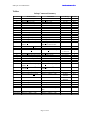
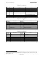
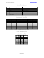
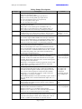
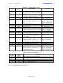
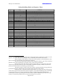
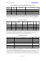
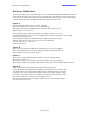
Industronics
Design, Application and Service of Electronics in Industry
InStep IV User Manual
For Version I 5.06D
Relevant for hardware revision 0 and 1
13 March, 2014
27 Wanganui Road Kirrawee NSW Australia 2232
Phone: (02) 9545 6181 Fax: +61 2 9545 6181 Mobile: 0419 267 889
Email: [email protected] WWW: http://www.industronics.biz
A division of D.H. Enterprises Pty Limited A.B.N. 72 087 000 995
Industronics
InStep IV User Manual.doc
Overview
The InStep IV control module is intended to be used in conjunction with a stepper drive and motor or a
servodrive with step input and a servomotor. It provides stop/start registration control of processes such as
self-adhesive labelling, overprinting etc. This operation can be speed synchronised with another operation
such as the product conveyor or printing machine.
It is housed in a DIN rail mountable enclosure. The enclosure can be opened by operating two small
catches to enable the user to configure the unit via several jumpers located inside. This allows for
diversified applications while maintaining the same hardware minimising the need for several units to be
kept for spares.
The enclosure has 16 screw terminals and a five way bus connector on the bottom. The bus has two
connections for the RS-485 half-duplex communications bus, two connections for a differential master
encoder input and one connection for ground. Up to 32 units may be daisy chained or multi-dropped to
allow a user interface/PLC to control several axes of motion. It is also possible to order the module with
the RJ-12 jacks for communications and 24V master encoder input so it becomes compatible with the
older InStep I modules (Option /G, Rev. 0 only).
All inputs are independently jumperable to change their polarity for use with either sinking (NPN) or
sourcing (PNP) input devices. The outputs can be changed for sinking or sourcing type but all must be the
same type.
The amount of I/O available is in fact limited by the terminals fitted to this enclosure and an expansion
board is available which will plug onto the existing board and then fit into a wider enclosure that has 24
terminals. This provides more I/O and many other options.
There is a green and a red LED on the front. The green LED is to indicate that the internal 5V supply is
functional and the red LED indicates status.
In order to minimise the amount of firmware versions two of the input terminals have jumpers which can
select 1 of 3 available input signals and two of the output terminals can be jumpered to one or more of 4
available output signals. Also there are 8 jumpers to select various options. Three of these will usually be
used to select the unit’s address on the multidrop network.
Wiring
Power
A power supply of between 12 and 28 volts DC is required to be connected to terminals 1
and 2. The total power requirement is 100mA plus input and output currents.
Inputs
All input are required to either sink or source between 5 and 12mA at between 12 and 28
volts DC. Unless option /G is ordered the master encoder input is five volt differential RS422/RS485. Refer to jumper description table to select polarity of inputs.
Outputs
All outputs can sink or source up to 100mA each at the same voltage as supplied to the
power supply terminals. Unless option /G is ordered the STEP output is five volt differential
RS-422/RS485. Refer to configuration section for changing polarity. Note that at this time
only NPN outputs are available. As of Hardware Revision 1 PNP is now optional again.
Serial Communications
The serial communications via the bus connector is two wire (half-duplex mode) only. If the
/G option is ordered the serial communications is via two RJ-12 connectors and can be fullduplex 4-wire or half-duplex two wire type. Option /G not available on Rev. 1 PCB's. Rev.
1 provides for one RJ45 socket to be optionally fitted for comms and power.
Page 2 of 31
Industronics
InStep IV User Manual.doc
Configuration
Configuration consists of selecting the appropriate jumpers for your application and installing the
appropriate output driver IC in position IC9. The jumpers are fully explained in the jumper description
table. The unit is normally supplied with an NPN output driver IC, however it can be ordered with a PNP
type or changed in the field. The correct IC for NPN outputs is ULN2801A (Rev. 0) and ULN2803 for
Rev. 1. PNP for Rev. 1 only is UDN2985. Be sure to set jumpers J9 and J10 correctly to match the
installed IC or damage will result!
Mounting
The InStep module can be mounted on 35mm DIN rail and should be mounted with terminals 1 to 4
uppermost and the rail clip at the bottom. If the InStep module is disassembled to facilitate the changing
of jumpers etc, it should be reassembled so that terminals 13 to 16 are at the rail clip end of the housing. If
the module must be mounted on a vertically mounted DIN rail it should be mounted with terminal 1
lowermost. This would place the side label uppermost.
Serial Communications
Up to 32 modules may be daisy chained together to allow one master device to communicate with all units
using only one communication port. The address of each unit is selected via the first three jumpers on the
option port. Commands are issued by the master device in the system and the modules either simply act on
this command or respond if it was a query type command.
All messages to and from the InStep modules have the following field format:
Header, Address, Command, Optional value, Carriage return and an optional checksum.
e.g.; 1[0]P2AB<CR>[CHK]
Where,
• The semicolon character (3B hex) is the header. All messages on the network begin with this header
character.
• 1 is the destination address on the network. The PLC or computer, etc is always address zero. Jumpers
on the Option Port set the address of the InStep units. The valid range is 1 to 8 ASCII.
• [0] is the senders address in ASCII. This field is optional and is selected along with the checksum.
• P is the command. All messages from the master have this field. All responses from the InStep
modules do not have this field. Refer to the InStep Command Summary for more details
• 2AB is the value. Whether this field exists and its width depends on the command. All responses from
the InStep modules have this field.
• <CR> is the message terminator. All messages are terminated by a carriage return (0D hex) character.
• [CHK] is a message checksum. It is the two’s complement of the preceding bytes. This field is
optional but must/will be present if it is selected at bit 5 of OPTION2.
Some commands are queries only and so no value field is allowed.
Some command values are in decimal ASCII others are in hexadecimal ASCII.
All response values are in hexadecimal ASCII.
All hex digits A to F must be in upper case.
Leading zeroes are not required in commands but are tolerated.
Leading zeroes are always returned to the width of the value field.
Space and Line Feed characters in commands are ignored.
Responses are always directed to address zero.
By setting bit 4 of OPTION2, commands that do not expect a response and successful setting type
commands can be made to return an <ACK> character. Out of range data or invalid commands will result
in a <NAK>. When this is not set, or prior to I5.04, the only response is the result of the query or a
‘?<BEL>’ to indicate an error.
Out of range characters in data will cause unpredictable results. (i.e. other than 0 to 9 and A to F)
A semicolon anywhere in the command string (except the checksum position) will clear the input buffer
and start a new command/query reception. Previously the semicolon header was only scanned for after the
previous string was terminated by a carriage return. This meant that if a carriage return was garbled or lost
the next string would be appended to the previous one and both then ignored, as it would be an invalid
Page 3 of 31
Industronics
InStep IV User Manual.doc
string. Also the backspace character (08) will delete the previous character sent. This does not apply to the
header or address characters!
Command Descriptions
A - Advance
Function
Range
Default
Description
Sets the advance value or queries the current value.
0 to 65,535 decimal in command, 0 to FFFF hexadecimal in response.
300 (12C hex). 330 (14A hex) I5.05J to I5.05P. Was 180 (B4 hex.) prior to I5.05J
This command sets the number of steps to move after the gap sensor has activated. If a
value is entered that is less than the decel (F command) setting the stored value will be
equal to the decel setting. If the decel is adjusted this value must be entered again to adjust
the entered advance value. If the speed compensation is selected on the option port, it is
necessary to observe minimum values of advance so that the compensation can function
correctly. The amount of compensation varies with the speed (higher speed more
compensation, maybe up to 200 steps). In addition to this there must be sufficient advance
to do the deceleration which may be up to 100 steps depending on the speed. At present it is
necessary to re-calculate (re-enter) the label length if the advance is changed in gap-skip
mode. As of I5.05L changing the advance value will reset the missing label length and
restart the auto-teaching function.
B - Batch Count Not implemented yet (Temporary use implemented)
Function
Range
Default
Description
Sets or queries the batch counter. (Sets fixed move length).
0 to FFFFFF hexadecimal. (0 to 65,535 dec in command, 0 to FFFF hex in response).
0
This command forces a value into the batch counter register. Normally used to reset the
count. (Sets the length in steps of the move done when the fixed move mode is activated).
C - Total Count
Function
Range
Default
Description
Sets or queries the total label counter. (Implemented in I5.04L)
0 to 99 decimal
0
This command forces a value into the total counter register. Normally used to reset the
count. Counter only counts to 99 then rolls over back to 0. It is up to the master controller to
extend this count to a larger number by periodic polling.
D - Coder Delay Partial implementation
Function
Range
Default
Description
Sets or queries the coder delay.
0 to FFFF
0
This command sets the delay in steps between either the start of dispensing or the stopping
and the print signal coming on depending on the type of batch coder selected.
At the moment 0 disables and any value enables with a small delay. Any odd value causes
checking for a printer OK signal at IN4, even values look for a printer faulty signal.
E - Enable
Function
Range
Default
Description
Enables the dispensing of labels.
0 or 1
Depends on state of J28. (Refer to Option Port Table)
When set to 1 enables the dispensing of labels at the next product sensor activation or when
set to 0 disables the dispensing of labels at the end of the currently dispensing label. Also
used to reset faults.
Page 4 of 31
Industronics
InStep IV User Manual.doc
e – End of Reel Setpoint
Function
Range
Default
Description
Sets or queries the setpoint of the End of Reel counter.
0 to FF
3
How the “end of reel count” functions is determined by bit 6 in Option2. With this bit on,
the setting here is the number of labels that can be dispensed in between operations of the
‘end of reel’ sensor. The sensor detects the movement of the label reel. In this mode, the
number set here is usually quite low. With the bit off, it sets the number of labels that can be
dispensed after the ‘end of reel’ sensor activates. The sensor detects that the label reel is
low in diameter. The setting is usually larger in order to allow the reel to become very close
to finished before the head stops. In both modes, the setting depends on the label length.
F - Forward label Not implemented yet (Temporary use implemented)
Function
Allows the labeller to skip over a missing label to prevent one product not being labelled.
(Number of Deceleration Steps during end of advance.)
Range
0 to FF
Default
0 or off (prior to I5.05J was 10, I5.05J to I5.05P was 107, I5.05Q and on is 100)
Description The number of labels between the gap sensor and the peeler bar is set here. When the
missing label approaches the peeler bar a double length index is performed to skip over the
missing label allowing all products to be labelled. (Temporarily used for number of
deceleration steps. Re-enter advance after changing this value!) As of Ver. 5.05 this decel
setting is disabled. You can still request the current setting. Do not adjust this value!
f – Fault Status
Function
Range
Default
Description
Allows the query of the reason for the last disable
0 to 4FF (Prior to I5.06 was 0 to FF)
N/A
Refer to the Red LED Flash Code table for the correlation between the value returned
here and the reason for the disable.
G - Manual Dispense (Go)
Function
Range
Default
Description
Starts the label sequence independent of the product sensor.
No value allowed!
N/A
This command allows the operator to dispense a label without having to operate the product
sensor. Any product delay is bypassed and only one label is dispensed if in two label mode.
Also if the master is stopped the label will be dispensed at the set speed rate.
H - Batch Preset Not implemented yet
Function
Range
Default
Description
Sets or queries the batch preset value.
0 to FFFFFF hexadecimal
0 or off
This command sets the count at which the batch counter will activate the output and reset
the counter.
Page 5 of 31
Industronics
InStep IV User Manual.doc
I - Input Port Status
Function
Range
Default
Description
Returns a value indicating the status of the input port.
No value allowed!
N/A
This command returns two hex digits representing the status of the 8 bit input port. A value
of 00 is all off. Refer to the port assignment tables for the function of each input.
J - Jig Delay/Blanking Mode
Function
Range
Default
Description
Sets or queries the jig delay or blanking mode.
0 to 65,535 decimal in command, 0 to FFFF hexadecimal in response.
0 or off
This command sets the steps between product detection and activating the jig solenoid
output. A value greater than zero enables Jig Control Mode. If you select this mode you
must select a mode with the ’U’ command as well! As of version 5.05E setting this
command to 1 enables blanking mode rather than Jig Control mode. See “j” command
below.
j - Jig Hold Delay/Blanking Length
Function
Range
Default
Description
Sets or queries the jig hold delay.
0 to 65,535 decimal in command, 0 to FFFF hexadecimal in response.
0 or off
In Jig Control Mode this command sets the length between the dispense stopping and the
deactivation of the jig solenoid. It is up to the operator to ensure correct product spacing.
You must ensure the product is released before the following product is detected by the
product sensor or that product will be ignored. In Blanking Mode this setting sets the length
that the product sensor is ignored for after the label stops. In addition when blanking mode
is set, the product sensor is re-confirmed to be on at the completion of the product delay. If
only this product sensor confirmation is required, simply set a very short blanking length.
Blanking is useful when the trailing edge of the product has a possible second trigger point
because of a hole or handle etc. The product sensor re-confirmation is very good for
preventing false dispenses caused by product sensor activation while the machine is
stopped. This setting is only used when in Jig Control Mode or Blanking Mode which is
enabled by the J command above, so you can leave the value in here always.
K - Air Blast Time
Function
Range
Default
Description
Sets or queries the air blast time.
0 to 255 decimal in command, 0 to FF in response.
0 or off
This command sets the air blast time in milliseconds. The air blast is for machines with an
air box attachment. The air blast time occurs after the product delay and before the label
starts to move.
Page 6 of 31
Industronics
InStep IV User Manual.doc
L - Length Measuring
Function
Range
Default
Description
Turns the length measuring function on or off.
0, 1 or 2, Two is invalid since I5.05L
0 or off
This command turns the length measuring function on (1) or off (0). When turned on the
number of steps to dispense the label is transmitted to the master device shortly after the
label is dispensed. Value returned is number of steps in hexadecimal. From version I5.04 to
I5.05K, whilst length measuring mode is on, the “L2” command can be issued. This will
calculate the “no gap skip” missing label length and if successful, turn length measuring off.
l – Average Length
Function
Range
Default
Description
Displays the average length in steps.
No value allowed!
0000 hex
This command can be used to determine whether the automatically calculated missing label
length is in use and what the average dispense length is. When the unit is first powered up
the value will be zero. Also it can be reset by a change to either the advance value (A)/t) or
six consecutive labels have been dispensed that are all more than 99 counts different from
the current value.
M - Master Speed
Function
Range
Default
Description
Queries the speed of the master encoder.
No value allowed!
N/A
This command allows the user to check the operation of the master encoder. To convert the
value returned into a rate in kHz, divide the lowest 4 digits into 1250 decimal.
i.e. Speed (kHz) = 1250/Value. If value is 1F4 then 1250/500 = 2.5kHz.
Note: This is the time between the last two encoder pulses so when the encoder has a
stopped a value will still be indicated. The returned value is actually 6 digits of
hexadecimal, the first digit indicates whether of not the master is considered as stopped or
not. (1 = stopped and so value is invalid, 0 = running and value following is valid). The
second digit is used internally to detect a stopped condition. It will normally show 8 except
at extremely low encoder rates.
N - Missing Label Length
Function
Range
Default
Sets or queries distance required to trip on missing label fault.
0 to 65,535 decimal in command, 0 to FFFF hexadecimal in response.
<I5.05Y is 48 (12,288 steps), I5.05Y & I5.06 is 64 and >I5.06 is 80 (20480 steps or
620mm at 33p/mm or 1.024m @ 20p/mm)
Description The missing label function can work in either of two ways:
If the value entered here is less than 128 (63 prior to I5.03) the missing label function works
as before except that the number of steps is set differently. The number of steps at which the
labeller will stop is 256 times the value set here. So a value of 16 gives the same as the old
default value of 5 (256 x 16 = 4096). This gives a much more precise way to set the trip
point.
If the value is greater than 127 the “no gap skip” style of missing label is implemented. This
allows the labeller to skip past missing labels (or blocked label gaps) as if they never
happened. Since I5.05J and L (not K) auto-teach missing label is implemented. This
automatically sets this value. As there is no way at the moment to switch off auto-teach
setting this value is not very useful. A value of 0 here disables the missing label function
and the motor will run works by simulating the label gaps presence at the number of counts
specified here. So the number entered here should be the label length minus the label
advance setting. If the actual gap occurs after the gap is simulated, the actual gap position
will override the simulated one to maintain correct registration. If you change the advance
Page 7 of 31
Industronics
InStep IV User Manual.doc
after setting this value you should redo this setting to cater for the new advance value. If the
“gap skip” is done four times consecutively the labeller will disable and turn on the Missing
Label and Bussed Fault Outputs. Also, refer to L command. Note forever if no gap is seen.
0 also stops auto-teaching of this setting as of version I5.05P. Care must be exercised when
using low values of advance at high speed. As the gap is ignored after the web starts to
decelerate it is possible that no correction is done when the gap comes along after the gap
has been simulated and deceleration has already started.
O - Output Port Status
Function
Range
Default
Description
Returns a value indicating the status of the output port.
0 to FF hexadecimal
N/A
This command allows the user to force the state of the output port bits. As a query it returns
two hex digits representing the status of the 8-bit output port. A value of 00 is all off. Refer
to the port assignment tables for the function of each output.
P - Label Position
Function
Range
Default
Description
Sets or queries the label position value.
0 to 65,535 decimal in command, 0 to FFFF hexadecimal in response.
0
This command sets the delay in steps between the product sensor activation and the start of
dispense effectively changing the position of the label on the product.
Q and q - Stop Dispense (Quit)
Function
Range
Default
Description
Used to stop the dispense of a label.
No value allowed!
N/A
This command stops the label dispense independent of the gap sensor. ‘Q’ simulates the gap
sensor signal; ‘q’ causes instant deceleration and stop (i.e. no advance).
R - Ramp Select
Function
Range
Default
Description
Sets or queries the acceleration ramp.
0 to 13 (Was 0 to 5 prior to V5.05A)
4 (Was 3 prior to V 5.05B)
This command selects 1 of 14 acceleration ramp profiles. A value of 13 is the softest. As of
V5.05A the ramps are now linear whereas previously they had very high rates of
acceleration towards the end of the curve. The acceleration profiles are performed over the
following number of steps.
Ramp Number
0
1
2
3
4
5
6
7
8
9
10
11
12
Number of Steps
10
15
20
30
40
50
60
75
85
100
125
150
175
Page 8 of 31
Industronics
InStep IV User Manual.doc
13
200
r – High Page Register Read
Function
Returns the value stored at the specified High Page Register address. Value in command is
an index added to 1800 hexadecimal
Range
0 to A hexadecimal in command as index, no data is latched SRS. 0 to FF returned as data.
Default
N/A
Description This command is for debugging purposes only and requires an intimate knowledge of the
MPU hardware to interpret the responses.
S - Set Speed
Function
Range
Default
Description
Sets or queries the set speed
0 to 9999 in command, 0 to FFFF hexadecimal in response.
120 hex, As of I5.05Q default is now 200 hex. Or equivalent to S9537
This command sets the speed of dispensing when no master encoder is used. Sync ratio of
zero must be set for this value to take effect. Also this value will be used if a manual
dispense is done with the master stopped. A value in the 9000’s is typical with a larger
number being a faster speed. Now as of I5.05S the default set speed depends on J29. If on
the default is 200hex (S9537) or when off it is 120hex (S9761) also the scaling was changed
slightly. The returned value is not scaled!
T - Two Label Spacing
Function
Range
Default
Description
Sets or queries the two label spacing value
0 to 65,535 in command, 0 to FFFF in response.
0 or off
This command sets the number of steps to pause between the first and second label of a set.
A value of 0 turns this function off. Note that as of V 5.05D there is a minimum spacing
caused by the deceleration/acceleration between the two labels. Prior to this version the first
label stopped with no deceleration and the second started with no acceleration
t - Two Label Spacing Advance
Function
Range
Default
Description
Sets or queries the two label spacing advance value
0 to 65,535 in command, 0 to FFFF in response.
300 (12C hex.)
This command sets the number of steps of advance for the first label of a two label set. This
is set the same as ‘A’ if the labels are the same size in the set and often different if the labels
are different lengths. Note that labels of different lengths in a two label set causes confusion
for the auto setting missing label as it does not measure the two labels separately. This will
be upgraded in the future.
U – Spin Up Delay
Function
Range
Default
Description
Sets or queries the spin up delay.
0 to 65,535 in command, 0 to FFFF in response.
0 or off
This command can enable one of two modes. A value of 1 puts the InStep into “Jig Only
Mode”. In this mode the normal product sensor is ignored and the sequence is started by the
“Jig In” input. When a larger value is entered, the “Orient Jig Mode” is turned on. This
command sets the number of steps to pause before the registration scanner is enabled. This
is to ensure the product is spinning in the jig at the correct speed. In orient jig mode the
normal product scanner is ignored and the cycle is initiated by a sensor connected to the
“Jig In” input. This initiates the spin up delay. When this is complete, the sensor connected
Page 9 of 31
Industronics
InStep IV User Manual.doc
to the “Colour Sensor” input is enabled. When the colour sensor sees a leading edge the
normal dispense sequence is started. A value of 0 turns both jig modes off.
u - Option Port 3
Function
Range
Default
Description
Sets or queries the Option3 port status. Implemented in V I5.05M
00 to FF.
00.
Two hex digits representing the status of the 8-bit option3 port. A value of 00 is all off.
Bit 0 – Fixed Pull Mode.
Only bit 0 is used at this time. Setting the other bits will have no effect.
V - Version
Function
Range
Default
Description
Queries the version number of the installed firmware.
No value allowed!
N/A
This command returns the installed firmware’s version number in the following format:
A letter to indicate the type.
A major version number followed by a decimal point.
Two minor version digits to indicate revision level.
A space or letter to indicate special versions.
v – Serial Number
Function
Range
Default
Description
Queries the serial number of the device.
No value allowed!
N/A
This command returns the serial number in the following format:
A letter to indicate the number or versions this unit has had. (A is original)
The serial number in decimal in a fixed six digit format.
W - Option Port (DIP Switch)
Function
Range
Default
Description
returns a value indicating the option port status.
No value allowed!
N/A
Returns two hex digits representing the status of the 8-bit option port, refer to the port
assignment tables for the jumper functions. A value of 00 is all off. Also used to load a
new setting. Bit 0 corresponds to J24.
w - Option Port 2
Function
Range
Default
Description
Sets or queries the Option2 port status.
00 to FF.
00.
Two hex digits representing the status of the 8-bit option2 port. A value of 00 is all off.
Bit 7 – Output frequency equals input frequency. 0 is normal Out = In x 2 (Double)
Bit 6 – End of Reel Mode. When on selects reel turning detection type and when off selects
reel diameter low or no web type detection. Set to 0 if no end of reel sensor is fitted.
Bit 5 – Use Checksum. When set it is necessary to send a two’s complement checksum byte
after the <CR> byte. Responses will then include this byte also.
Bit 4 – Acknowledge mode. <ACK> and <NAK> sent/expected.
Bit 3 – Stepper Boost. When on changes the servo enable output function to a stepper drive
boost.
Bit 2 – Servo OK input polarity. 0 is Off = OK. 1 is On = OK.
Bit 1 – Orientation Error Enable.
Page 10 of 31
Industronics
InStep IV User Manual.doc
Bit 0 – Gap Sensor Gate Mode. (I5.05H) was Fixed Pull Mode prior to this.
X - Examine RAM
Function
Range
Returns the value stored at the specified RAM address.
0 to 9FF hexadecimal in command as address, 0 to FF returned as data.
The range for address is limited by the MPU. GT16 = 47F, GT16A = 87F
Default
N/A
Description This command is for debugging purposes only and requires an intimate knowledge of the
firmware to interpret the responses.
Y - Synchronisation Ratio
Function
Range
Default
Description
Sets or queries the sync ratio
0 to 255 decimal in command, 0 to FF in response.
128 decimal (80 hex) or 100%
This command sets the sync ratio between the master encoder and the output pulse rate FF
is 50%, 10 is 800% Refer to table for correct value. A value of 0 causes the master encoder
to be ignored and the set speed value to take effect.
Z - Internal Port
Function
Range
Default
Description
Returns a value indicating the internal port status or can force output bits.
0 to FF
N/A
Returns two hex digits representing the status of the 8 bit internal port, refer to the port
assignment table for individual bit functions and states. A value can be written to the port
in order to force the state of the output bits on that port, the input bits remain unaffected.
[ - Write RAM
Function
Range
Writes the specified data into the specified RAM location.
0 to 9FF hexadecimal in command as address, 0 to FF returned as data.
The range for address is limited by the MPU. GT16 = 47F, GT16A = 87F
Default
N/A
Description This command has a special data format, there are two data fields separated by a comma.
The data in front of the comma is the address to write to and the data after the comma is the
data to be written. This command is for debugging purposes only and requires an intimate
knowledge of the firmware to use it successfully.
Inputs
All inputs are selectable for NPN (1 to 2) or PNP (2 to 3) input devices. The function of
each input follows.
PRODSENS - Product Sensor
This input initiates the labelling sequence. It starts with a transition from off to on of this
input. See jumper J7 for input polarity selection. Terminal 9 on a standard InStep.
GAPSENS - Gap Sensor
This is the registration input. It is normally connected to a fork sensor that detects the gap
between the labels on the backing paper. The label advance starts counting with an off to on
transition of this input. See jumper J8 for input polarity selection. Terminal 10 on a standard
InStep.
Master Encoder
This is where the encoder for the product speed is connected. The encoder is usually
coupled to the conveyor, turret or vacuum belt of the machine. The pulses per rev of the
Page 11 of 31
Industronics
InStep IV User Manual.doc
encoder and its gearing to the conveyor / belt should be selected so that the rate is the same
as the step rate of the motor. It is best to be on the low side of one to one if this cannot be
achieved. The encoder should have a 5V differential output. If the /G option is fitted the
encoder should have a 24 volt NPN/PNP output. Terminal 11 becomes the A input. Without
/G the master encode is connected to the buss connector, usually via a HeadUnit. The
HeadUnit also allows for the correct scaling of the encoders pulse rate.
IN1 – Colour Sensor (Product Sensor 2)
This input only functions in Orientation Mode. It triggers the labelling cycle just as the
normal product scanner does however only after the orient part of the cycle is complete. See
jumper J1 for input polarity selection. Terminal 5 on a standard InStep.
IN2 – Jig In Sensor/Product Gate/Gap Sensor Gate
This input is usually a proximity detector mounted on the orientation jig to indicate when
the jig is closed. It initiates the spin up delay in orient jig mode. If option port jumper J31 is
installed this input becomes the product sensor gate input. In this mode this input must be
on before a product detection will start the dispense cycle. If bit 0 of ‘w’ command is set
this input becomes a gate signal for the gap sensor (>=I5.05H) See jumper J2 for input
polarity selection. Terminal 6 on a standard InStep.
IN3 – End of Reel
This input is either connected to a sensor that detects a low diameter of labels on the unwind
reel or one that pulses as the unwind reel turns. Refer to the description of ‘e – End of
Reel Setpoint’ menu. See jumper J3 for input polarity selection. Terminal 7 on a standard
InStep
IN4 – Printer OK
This input is connected to the printer OK/fault output of the printer controlled by the InStep
module. When the printer is enabled by the Coder Delay (D) command with an odd value
this input must be on otherwise the InStep is disabled and the bussed fault output is turned
on. If an even value is used in D the input must be off for printer OK. The printer fault input
is only checked just after the label dispense is completed. This allows it to possibly serve as
an actual print confirmation input (from a contrast scanner for instance) or just a simple
printer fault signal monitor. See jumper J4 for input polarity selection. On a standard
InStep, J21 controls which terminal this signal is connected to. 1 to 2 is terminal 8, 2 to 3 is
terminal 12.
IN5 – Servodrive OK
This input is connected to the OK or fault output of the servo/stepper drive. See Option2
command for input polarity setting. It stops and disables labelling when changes to the
selected faulty state. As of V5.04F this input is only checked when labelling is enabled. As
of V5.05A, when faulty the drive pulses are stopped and the drive enable is dropped
immediately. Previously it was only done at the end of the dispense cycle. J22 controls
which terminal this signal is connected to. 1 to 2 is terminal 8, 2 to 3 is terminal 12.
IN6 - Disable (Bussed Fault In)
This input disables the labelling when on. It is normally used in the “bussed” mode where
jumper J34 on InStep (or J60 on the Expansion Board) is installed. When several units are
connected together via their IN6 or OUT7 terminals all units will be disabled when a fault
occurs on any one unit. See J6 for input polarity selection. On a standard InStep J23
controls which terminal this signal is connected to. 1 to 2 is terminal 8, 2 to 3 is terminal 12.
Note: IN6 and OUT7 polarities must be the same and on InStep J20 and J23 must be set
correctly to bring them out to terminals.
Page 12 of 31
Industronics
InStep IV User Manual.doc
Outputs
All outputs are selectable for NPN or PNP however they must all be one or the other.
Selection is made by changing IC9. For NPN use ULN2801A. No PNP option at present.
Jumpers J9 and J10 must be set to suit.
STEP – Step Signal
This differential output is used to drive the pulse input of the stepper or servo drive.
Terminal 11 is A/ and terminal 12 is A. If jumper J37 is set 1 to 2 the STEP signal is
available as an open collector NPN signal on terminal 3. If using the differential output to
the drive, J37 should be set 2 to 3.
OUT1 – Coder
This output is the start trigger for a date coder etc. Jumper J27 selects whether the coder is
of the type that prints while the web is stationary (e.g. hot stamp) or moving (e.g. ink jet).
Terminal 13 on a standard InStep.
OUT2 – Servo Enable
This output is used to enable/disable a servo/stepper drive when a fault occurs or it is
commanded so. May also be used to enable/disable web winder drives as well. Terminal 14
on a standard InStep.
OUT3 – Missing Label (Labeller Fault)/Rewind Inverter Enable
This output is turned on when a missing label has been detected. It is reset by sending the
“E1” command. As of I5.05K this output changes function to Rewind Inverter Enable if
checksums are enabled in the w command. Terminal 15 on a standard InStep.
OUT4 – Jig Solenoid
This output connects to the solenoid that controls jig closure. J17 controls which terminal
this signal is connected to. 1 to 2 is terminal 16, 2 to 3 is terminal 4
OUT5 – Air Blast
This output is turned on when an air blast time is entered with the K command at the end of
the product delay and before the servo starts to move. J18 controls which terminal this
signal is connected to. 1 to 2 is terminal 16, 2 to 3 is terminal 4.
OUT6 – Air Assist
This output is turned on at the start of the servo moving and off at the beginning of decel.
J19 controls which terminal this signal is connected to. 1 to 2 is terminal 16, 2 to 3 is
terminal 4.
OUT7 – Bussed Fault Out
This output is turned on when there is a fault. Please refer to the table for all the faults.
Fault code 02 and greater will turn the output on. The enable command clears the faults.
This output can be tied to input 6 with J34 on a standard InStep to implement the “bussed
fault” mode. J20 controls which terminal this signal is connected to. 1 to 2 is terminal 16, 2
to 3 is terminal 4.
Page 13 of 31
Industronics
InStep IV User Manual.doc
Tables
InStep Command Summary
Command
A
B
C
D
E
e
F
f
G
H
I
J
j
K
L
Without Data
Returns Advance Value
Returns Batch Count
Returns Total Count
Returns Coder Delay
Returns Enable Status
Returns EOR Setpoint
Returns Forward Label Value
Returns reason for disable.
Manual Dispense (Go)
Returns Batch Preset Value
Returns Input Port Status
Returns Jig Delay
Returns Jig Hold Delay
Returns Air Blast Time
Returns Length Measure
Status
Returns Average Length
Returns Master Speed
Returns Missing Label Status
With Data
Sets Label Advance
Sets Batch Count
Sets Total Count
Sets Coder Delay
Sets Enable On or Off
Sets EOR Setpoint
Sets Forward Label Count
Returns ?<BELL><CR>
Returns ?<BELL><CR>
Sets Batch Preset
Returns ?<BELL><CR>
Sets Jig Delay
Sets Jig Hold Delay
Sets Air Blast Time
Sets Length Measure On or
Off or sets mislab value
Returns ?<BELL><CR>
Returns ?<BELL><CR>
Sets Missing Label Length
Sets Output Port Bits
Sets Label Position
Returns ?<BELL><CR>
Returns ?<BELL><CR>
Selects Acceleration Ramp
Sets Set Speed
Sets Two Label Spacing
U
u
V
Returns Output Port Status
Returns Label Position Value
Manual Stop Dispense (Quit)
Manual Instant Stop
Returns Selected Ramp
Returns Set Speed
Returns Two Label Spacing
Value
Returns Two Label 1st Label
Advance
Returns Spin Up Delay Value
Returns Option Port 3 Status
Returns Firmware Version
v
Returns Serial Number
Returns ?<BELL><CR>
W
w
X
Y
Z
Returns Option Port Status
Returns Option2 Status
Returns ?<BELL><CR>
Returns Sync Ratio
Returns Internal Port Status
Returns ?<BELL><CR>
Sets Option2 Port
Returns RAM value
Sets Sync Ratio
Sets Internal Port Output
Bits
Write data to RAM location
Returns ?<BELL><CR>
l
M
N
O
P
Q
q
R
S
T
t
[
Any Other
Returns ?<BELL><CR>
Returns ?<BELL><CR>
Sets Two Label 1st Label
Advance
Sets Spin Up Delay
Sets Option3 Port
Returns ?<BELL><CR>
Page 14 of 31
Data Range
0 to 65535
0 to 65535
0 to 99
0 to FFFF
0 or 1
0 to 255
0 to FF
0 to FF
N/A
0 to FFFFFF
0 to FF
0 to 65535
0 to 65535
0 to 8191
0, 1 or 2
Default
330 dec.
0
N/A
?
0
3
10 dec.
N/A
N/A
0
N/A
0
0
0
0
0 to FFFF
0 to 1FFFFF
0 to 65535
<3.20 0 to 8
0 to FF
0 to 65535
N/A
N/A
0 to 13
0 to 9999
0 to 65535
N/A
N/A
16
5
N/A
0
N/A
N/A
4
9743 d
0
0 to 65535
330 dec.
0 to 65535
00 to FF
A0.00 to
Z9.99Z
A000000 to
Z999999
0 to FF
0 to FF
0 to 9FF
0 to 255
0 to FF
0
0
N/A
N/A
0
N/A
128 dec
N/A
0,0 to 9FF,FF
N/A
N/A
Industronics
InStep IV User Manual.doc
Option Port Assignment
Option
Number
1
2
3
4
5
6
Jumper
Number
J24
J25
J26
J27
J28
J29
7
8
J30
J31
Description
Notes
Address Bit One
Address Bit Two
Address Bit Three
Coder Type Select
Enable State On Power Up Select
Select Direct coupled motor or 2:1 belt
drive (Prior to 5.05C was SIG)
Speed Compensation Factor
Product Sensor Gate
Refer address selection table
Refer address selection table
Refer address selection table
On = Moving Type 1
On = Enabled at power up
On = Direct, Off = 2:1 belt drive
(Was on for SIG) Also On is 20
pulses per millimetre, Off is 33.
On = Apply for Servodrives
On = Gate sig Req’d on IN2.
Input Port Assignment
Input
Number
1
2
3
4
5
6
7
8
Description
Colour Sensor
Jig In Sensor / Prod Gate
End of Reel Proximity
Printer OK
Servo OK
Disable (Bussed Fault In)
Product Sensor
Gap Sensor
Terminal
Number
5
6
7
8/12
8/12
8/12
9
10
Notes
Orient Mode Only
Orient Mode / J31 / ‘w’ command
Refer to the ‘e’ & ‘w’ commands
Terminal 12 only available with Opt. /G
Used in Commander systems (J22 1-2)
Linked to Output 7 by J34
Product detection Sensor
Label Gap Sensor
Output Port Assignment
Output
Number
1
2
3
4
5
6
7
8
Description
Coder
Servo Enable
Missing Label
Jig Solenoid
Air Blast
Air Assist
Bussed Fault Out
Out 8
Terminal
Number
13
14
15
16/4
16/4
16/4
16/4
3
1
Notes
Refer to Note 1
On = Missing label Fault
No signal assigned yet
When moving type coder is selected and enabled via the D command, the output will come
on just after the acceleration has completed and turn off just after the label stops. The opposite will occur
when this jumper is off.
Page 15 of 31
Industronics
InStep IV User Manual.doc
Internal Port Assignment
Bit
Number
0
1
2
3
4
5
6
7
Description
Notes
PC0
PC1
PC2
PC3
Red LED
Option Port Load Output
RS-485 Receive Enable Output
Not on MCU
Connector EXP2 Pin 5
Connector EXP1 Pin 10
Connector EXP1 Pin 8
Connector J36 Pin 1
0 = LED On
1 = Load enabled
0 = Receiver enabled
Synchronisation Value Table
Sync Percent
50
60
70
80
90
100
110
120
130
140
150
Value in Dec
255
213
183
160
142
128
116
106
98
91
85
Value in Hex
FF
D5
B7
A0
8E
80
74
6A
62
5B
55
Sync Percent
160
170
180
190
200
250
300
400
600
800
Value in Dec
80
75
71
67
64
51
42
32
21
16
To calculate the value to use with the Y command, use the following formula:
Y value = 12800 / Sync in percent
Address Selection Table
Bit 3
J26
Off
Off
Off
On
On
On
On
Off
Bit 2
J25
Off
On
On
Off
Off
On
On
Off
Bit 1
J24
On
Off
On
Off
On
Off
On
Off
Page 16 of 31
Address
1
2
3
4
5
6
7
8
Value in Hex
50
4B
47
43
40
33
2A
20
15
10
Industronics
InStep IV User Manual.doc
InStep Jumper Descriptions
Jumper
J1 to J8
J9 and J10
J11 and J12
J13 and J14
J15 and J16
J17 to J20
J21 to J23
J24 to J31
J32 and J33
J34
Description
These three point jumpers select the polarity of the signal
required to operate the inputs.
Jump 1 to 2 for sinking (NPN) type input devices.
Jump 2 to 3 for sourcing (PNP) type input devices.
J1 to J6 correspond to input 1 to 6 respectively.
J7 is for the product sensor input.
J8 is for the label sensor input.
These jumpers are set to match the type of output driver IC
installed in position IC9.
Jump both 1 to 2 for NPN type IC (ULN2801A Rev. 0)
Jump both 2 to 3 for PNP type IC (Not available on Rev. 0)
Note: jumpers must be set correctly or damage will result!
These jumpers connect the transmit and receive signals between
the RS 485 driver IC and the microcontroller. They are always
installed except when an option card connects to these pins
J13 connects signal TXA to RXA on the serial port connectors.
J14 connects signal TXB to RXB on the serial port connectors.
These are both jumpered for 2 wire half-duplex RS485 comms
and both off for 4 wire full duplex RS485/RS422 comms. Rev. 1
PCB's do not have this jumper, it is permanently jumpered.
These jumpers connect a resistive termination network to the
receive lines of the serial port connectors.
These are both jumpered to connect the termination network.
Note: The termination network should only be connected in the
last unit connected to the RS485/RS422 network. Rev. 1 PCB's
do not have this jumper, R11 to R13 must be soldered in to
provide network termination now.
These jumpers connect output signals OUT4, OUT5, OUT6 and
OUT7 to either output terminal 16 (OUTA) or terminal 4
(OUTB). As there are insufficient terminals for all the signals
available, these jumpers allow the user to choose which signals
are brought out to the terminals.
Jumpering 1 to 2 brings the respective signal out on OUTA and
jumpering 2 to 3 connects it to OUTB. Beware of possible
conflict with inputs if J38 is 2 to 3.
These jumpers connect input terminals 8 (INA) and 12 (INB) to
either input signal IN4, IN5 or IN6. As there are insufficient
terminals for all the signals available, these jumpers allow the
user to choose which signals are connected to the terminals.
Jumpering 1 to 2 connects the respective signal to INA and
jumpering 2 to 3 connects it to INB.
When differential STEP out is fitted (normally is) pin 3 of J21 to
J23 is not fitted as this is used for differential output. Rev. 1 is
different.
These jumpers select various software options.
These options may change with the software version. Refer to
separate table for usage
These jumpers are set to match the polarity of the output of the
master encoder connected to terminal 11.
Jumper J32 and J33 1 to 2 for NPN output encoders.
Jumper J33 2 to 3 and J32/1 to J33/1 for PNP output encoders.
These pins are not fitted unless option /G is ordered.
This jumper when installed connects IN6 to OUT7 for a bussed
fault line to use between multiple units. Ensure J6 is set to match
output IC if this jumper is fitted. J34 is actually pins 1 & 2 of
P6. Rev. 1 PCB's have this linked via a track on the rear.
Page 17 of 31
Default
1 to 2 jumpered
1 to 2 jumpered
1 to 2 jumpered
linked by a track on
rear side.
1 to 2 jumpered
Jumpers off
J17, 1 to 2 jumpered
J20, 2 to 3 jumpered
J18 and J19 jumpers
off
J21, 1 to 2 jumpered
J22, jumper off
J23, jumper off
If used with
commander then J22
only is jumpered 1
to 2.
Refer to option port
table.
J32, 1 to 2 jumpered
J33, 1 to 2 jumpered
Installed
Industronics
InStep IV User Manual.doc
J36
J37
J38
Used to route additional signals to Rev. 1 Exp. Board only.
When set 1-2 routes signal TCMP through the output driver and
on to terminal 3 for use as an NPN STEP output. If fitted 2-3 the
PB7 signal is connected to produce OUT8 on term. 3.
Rev. 1 PCB's only and is wrongly marked J34 (near R11).
Routes pin 3 of J21 to J23 to either OUTA (1 to 2) or
INB/STEPA (2 to 3)
Page 18 of 31
Not Fitted
If option /G, 1 to 2
otherwise 2 to 3.
Jumpered 1 to 2 by a
track on rear of PCB
Industronics
InStep IV User Manual.doc
Terminal
Number
InStepIV Terminal Descriptions
Terminal
Description
Name
1
+24V
2
0V
3
4
OUT8
/G = STEP
OUTB
5
6
7
8
IN1
IN2
IN3
INA
9
10
11
PRODSENS
GAPSENS
Step A/
/G = ENC
12
Step A
/G = INB
13
14
15
16
OUT1
OUT2
OUT3
OUTA
Connect a 12 to 28 volt power supply to
this terminal to provide the InStep module
with power.
This is the 0 volt reference terminal for the
power supply and the I/O terminals.
This is a general purpose output as yet
unassigned. If /G option it is STEP output.
This is an output terminal.
Its function depends on jumpers J17 to
J20.
Polarity depends on IC9.
Product Sensor 2 input.
Jig In/Product Gate input.
End of Reel input
This is an input terminal.
Its function depends on jumpers J21 to J23
This is the product sensor input terminal.
This is the label gap sensor input terminal.
This is the differential step output A.
If option /G this is the master encoder
input terminal.
This is the differential step output A/
If option /G is fitted it is INB.
Its function depends on jumpers J21 to
J23. J21-23 pin 3 not fitted without /G
Printer output.
Servo Enable/Stepper Boost output.
Missing Label output
This is an output terminal.
Its function depends on jumpers J17 to
J20.
Polarity depends on IC9.
Buss Connector Descriptions
Terminal
Number
1
2
3
4
5
Terminal
Name
Enc. A
Enc. A/
0V
485A
485B
Description
Master Encoder Input RS-485 channel A.
Master Encoder Input RS-485 channel A/.
0 volts reference.
RS-485 communications A side.
RS-485 communications B side.
Note: Buss connector not accessible with option /G
Pin 1 is at top (nearest screw terminal 1 to 4)
Page 19 of 31
Comment
Polarity depends on IC9
Refer to jumper J37
J17 2 to 3 equals OUT4
J18 2 to 3 equals OUT5
J19 2 to 3 equals OUT6
J20 2 to 3 equals OUT7
J1 controls polarity
J2 controls polarity
J3 controls polarity
J21 1 to 2 equals IN4
J22 1 to 2 equals IN5
J23 1 to 2 equals IN6
J7 controls polarity
J8 controls polarity
J32 and J33 control
polarity
J21 2 to 3 equals IN4
J22 2 to 3 equals IN5
J23 2 to 3 equals IN6
Polarity depends on IC9
Polarity depends on IC9
Polarity depends on IC9
J17 1 to 2 equals OUT4
J18 1 to 2 equals OUT5
J19 1 to 2 equals OUT6
J20 1 to 2 equals OUT7
Industronics
InStep IV User Manual.doc
InStep Labelling Modes and Sequence Chart
Step No.
1
2
3
4
5
6
7
8
9
10
11
12
13
14
15
16
17
18
19
20
21
22
23
24
25
26
27
28
Step
Product Input On
Product Gate Input On2
Jig Delay
Jig Solenoid Output On
Jig In Input Off4,5 (Jig In)
Spin Up Delay6
Colour Sensor/Prod 2 Input7
Label Position Delay
Air Blast Output On
Air Blast Time
Air Blast Output Off
Air Assist Output On
Acceleration
Printer Output Off/On
Run in Sync or Set Speed
Gap Sensor Input On
Label Advance
Air Assist Output Off
Two Label Spacing Delay
Back to step 9 on first pass
Deceleration
Knife Down On/Up Off
Knife Down Time
Knife Up On/Down Off
Jig Hold Delay
Jig Solenoid Output Off
Printer Output On/Off
Product Input Enabled
Comments
All modes except Jig Only/Orient and Man Dispense
Only if selected on option port (InStep I J31 or InStep II bit 7)
Jig Control Mode Only3 (Jig Delay > 0)
Jig Control Mode Only (Jig Delay > 0)
Jig modes only (Jig Only/Orient Mode starts here) (S U D > 0)
Orient jig mode only (Spin Up Delay > 1)
Orient jig mode only (Spin Up Delay > 1)
All modes except manual release
Air Blast Mode Only (Man Dispense starts here) (AB Time > 0)
Air Blast Mode Only (Air Blast Time > 0)
Air Blast Mode Only (Air Blast Time > 0)
All modes
All modes (Except 2nd label of two label set)
Only if Printer enabled (D > 1) (Off/On selected on option port)
All modes
All modes
All modes (Gets setting from t command on 1st label of 2 label)
All modes
Two Label Mode Only (Two Label Spacing > 0)
Two Label Mode Only (Two Label Spacing > 0)
All modes (Not done on 1st label of 2 label set)
Knife Mode Only (Option2 bit 4 on and Knife Down Time > 0)
Knife Mode Only (Option2 bit 4 on and Knife Down Time > 0)
Knife Mode Only (Option2 bit 4 on and Knife Down Time > 0)
Jig Control Mode Only (Jig Delay > 0)
Jig Control Mode Only (Jig Delay > 0)
Only if Printer enabled (D > 1) (Off/On selected on option port)
Only if labelling still enabled (E = 1)
2
If selected, the Gate Input must be on at the instant of the product sensor coming on or the
sequence will restart. Therefore, the timing is always controlled by the Product Sensor Input.
3
When using Jig Control Mode you must select either Jig Only or Orient Jig Mode as well.
If not, the sequence will stall after the Jig Solenoid is turned on.
4
The sense of the Jig In Sensor Input has been changed so that off = jig in. This was done to
allow the use of a more standard N.O. proximity sensor in the orient jig mechanism.
5
Because the Product Gate and Jig In share the same input, it is not practical to have both
enabled at the same time. However, this is not normally a limitation as gating is usually only used on a
rotary type machine where an orientation jig cannot be fitted
6
The Spin Up Delay is used to ensure the product is spinning smoothly in the jig before the
Colour Sensor/Prod 2 is enabled. This prevents false triggers from the Colour Sensor.
7
Sending at least a semicolon followed by the address over serial port while waiting for the
colour sensor input to be activated will cause the sequence to reset without dispensing. This was changed
in version I5.04N, now you need to send either the disable command (E0) or the manual dispense
command (G) to release a jig waiting for the colour sensor to operate. Additionally you may force open
the jig or re-activate the product sensor to cause an orientation error as before.
Page 20 of 31
Industronics
InStep IV User Manual.doc
Serial Communication Sockets Pin Descriptions (Option /G only)
Pin
Number
Pin
Name
1
2
3
4
5
6
GND
TXA
TXB
RXA
RXB
GND
Description
Comment
0 volt or ground
Transmit positive side
Transmit negative side
Receive positive side
Receive negative side
0 volt or ground
Transceive positive side if J13 installed
Transceive negative side if J14 installed
Same as pin 2 if J13 installed
Same as pin 3 if J14 installed
Note: Both serial communication sockets are wired together pin for pin. Two are provided to aid daisy
chaining multiple units together. Pin 1 is the leftmost when looking at a plug with the cable leading away
from you and the contacts facing down. When viewing the sockets, pin 1 is the one nearest terminals 9 to
12.
Servodrive Connections
InStep
Signal
InStep
Terminal
Signal
Description
Mitsu J3-A
CN1 Signal
Mitsu J3-A
CN1
Terminal
SERVENA
Step A
Step A/
+24V
0V
ServoOK
14
11
12
1
2
8 (J22 1-2)
Servo Enable
Step positive side
Step negative side
Power in positive
0 volt or ground
Servo Healthy
SON
PP
PG
DICOM
DOCOM
ALM
15
10
11
20, 21
46, 47
48
Note: The correct pulse multiplier in the Mitsubishi J3 servodrive is 109 for direct drives and 131 for 2:1
drives. This is often implemented in the servodrive as PA06:PA07 10900:100 or 131:1. Direct drives with
version I5.05C to P used 65.53:1, implemented as 6553:100. The speed compensation tables are
optimised for these values only. Refer to jumper J29 to select which table is in use.
Red LED Flash Codes
Red LED Status
Description
‘f’ Command
Off
On
1 Flash
2 Flashes
3 Flashes
4 Flashes
5 Flashes
Servo Enabled with no faults present
Servo Disabled and never been enabled since power on.
Disabled via serial command ‘E0’.
Disabled due to missing label fault.
Disabled due to fault input being turned on.
Disabled due to printer error being indicated
Insufficient advance to allow for deceleration and speed
compensation. Increase advance value or run slower.
Disabled due to Servo/Stepper Error
Disabled due to End of Reel Detected
Disabled due to Orientation Error
00
FF
01
02*
04
08
10*
6 Flashes
7 Flashes
8 Flashes
20
40
80
Note: The LED flashing feature is yet to be implemented. At present the LED simply indicates the enabled
status, use the ‘f’ command query to determine cause.
* As of I5.06 the value returned by the ‘f’ command has two bytes the lower byte remains as above. The
upper byte is as follows: Bit 0 indicates that the ‘t’ command value is insufficient rather than the ‘A’ value
when the lower code is 10. Bit 1 is dispense too long when lower byte is 02. Bit 2 is four simulations in a
row when lower byte is 02. Note that versions prior to 5.06C return the two bytes in the incorrect order!
Page 21 of 31
Industronics
InStep IV User Manual.doc
Hardware Modifications
In order to provide for special installations there are certain hardware modifications identified by a letter
in the Options field of the device’s label. They are described here. The InStepIV is also available in the
“Plus” version as with the older InStep. This enclosure has 24 terminals and its own options described by
a number. Please refer to the old InStep Plus manual for details on these options.
Option A
Special Additional card that plugs onto EXP1 and EXP2
It provides scaling from 0 to 10V to 0 to 3.3V and buffering.
The signal leaves the option PCB through pin 9 of EXP1 which is PB7 or AD7
Because of this J37 can not be 2-3.
Analogue signal comes in differently depending on whether the InStep is /G or not.
333/Orlando Webmaster uses /G so here the analogue signal comes in on EXP2/8 or Term 12 INB
and so J21 to J23 can't use 2-3.
Later Webmasters (Hidec) use differential output so INB is taken for this purpose.
Therefore the input now comes in on J17+J18 pin3 or OUTB Term4
This now means no 2-3 on J17 to J20
Firmware is the same.
Option B
This is a wire link from IN5 to IRQ done by linking IC8/16 to the via near MPU/11.
This is for Webmaster splice loop for the head speed input as the KBI interrupts are
more complex because of the two gap sensors.
Option C
This is for new Tagger feeder and knife versions it links IN1 to IRQ by linking
P8(EXP2)/7 to nearest via.
This is because there are 3 interrupt sources on these which used to be prod/gap on
IRQ and IN1 on KBI. Now prod/gap is KBI and IN1 is IRQ. Also for Tetra Pak belt feeder on rotary.
Option D
This is for Webmaster splice InStep (when differential out used not /G)
Later in Webmaster development when only Hidec and Orlando and 333's existed, a link
was added from OUT6 of splice InStep to PROD input of headloop InStep. This caused
a problem on non-/G type in that OUT6 could not come out of OUTB. All other outputs
are used up. So this link between J37/2 and R9/6 was added to all to keep them the same.
Not actually required on /G. Comes out on OUTB with J19 2-3.
Wire link is from InStep 1(splice) to InStep 3(headloop) b1/3 to b3/9 on Hidec which is
non-/G. B1/4 to b3/9 at 333's
Page 22 of 31
Industronics
InStep IV User Manual.doc
InStep IV Version Update Summary
Version I5.00 - 17/10/2005
Changes:
Fixes:
Additions:
First released version. None in use.
None.
None.
Version I5.00D - 25/06/2006
Changes:
Fixes:
Additions:
None.
Has several I5.01 fixes as they were discovered here.
Special version that has a direction output for a Tetra-Pak machine.
Version I5.01A - 06/07/2006
Special version for label head of WebMaster, has pulse output for average web speed calculation. Based
on I5.00 and I 3.25A
Changes:
First applied version.
Fixes:
None.
Additions: None.
Version I5.02S - 18/07/2006
Special version for WebMaster Splice Loop control, based on I5.00
Changes:
First applied version.
Fixes:
None.
Additions: None.
Version I5.02H - 24/07/2006
Special version for WebMaster head loop control, based on I5.00.
Changes:
First applied version.
Fixes:
None.
Additions: None.
Version I5.01 - 11/08/2006
Changes:
Fixes:
Additions:
Changed TXENA to end of transmit delay, now is Hi-Z during delay. Changed default
missing label from 16 to 48 to maintain old actual length.
Fixed a problem with FIXED command. Corrected incorrect polarity in signals to read
option port. Fixed problem with stopped detection caused by now frequency out is 2 times
input.
Rough version of speed compensation table added for 700W J3A servo. Uses old MR-C
jumper setting. Is roughly suitable for 400W J3A as well.
Version I5.02A - 02/09/2006
See I5.01A
Changes:
Fixes:
Additions:
TXENA change and missing label change as per I5.01.
None.
Speed compensation table as per I5.01.
Version I5.02 - 25/09/2006
Changes:
Fixes:
Additions:
Changed default values for set speed and advance. Set speed changed to 120 hex and
advance changed to 190 decimal.
None.
None.
Page 23 of 31
Industronics
InStep IV User Manual.doc
Version I5.03S - 28/09/2006
Special version for WebMaster Splice Loop control, based on I5.02S.
Changes:
None.
Fixes:
None.
Additions: Added special purpose output to signal head loop In Step that the dancer arm is too high
and it should stop. Implemented on output 6 (Air Assist) but linked across to OUT8 so
signal exits on terminal 3.
Version I5.03H - 28/09/2006
Special version for WebMaster head loop control, based on I5.02H.
Changes:
None.
Fixes:
None.
Additions: Added special purpose input to stop movement when it is on. Implemented on Product
Sensor input (Terminal 9)
Version X 5.00i - 21/10/2006
Changes:
Fixes:
Additions:
Special version for tagger infeed.
None.
None.
Version I5.03y - 26/10/2006
Changes:
Fixes:
Additions:
Special version for first J3 type tagger. Use normal version with w80 command now. This
one had forced output frequency = input frequency.
None.
None.
Version X 5.00FK - 26/10/2006
Changes:
Fixes:
Additions:
Special version for taggers with J3 servos. Has assemble time switch for feeder or knife.
None.
None.
Version I5.03 - 15/11/2006
Changes:
Fixes:
Additions:
Changed bit 7 of the ‘w’ command to make output frequency equal to input frequency
(normally is double). This bit was for End of Reel mode in a Servotron.
Missing Label now changes type above 127 rather than above 63
Red LED now correct if enable at power on selected on option port.
None.
Version I5.03T - 28/11/2006
Changes:
Fixes:
Additions:
Has two speed dispense for labels longer than pitch. Built on top of I5.03A. For 333’s
Removed redundant timer 2 interrupt service routine and vector. Needs doing in others!
None.
Version I5.04S - 19/12/2006
Changes:
Fixes:
Additions:
New version of loop controller for single loop WebMaster. For Cerebos machine
None.
None.
Version I5.02B - 21/12/2006
Changes:
Fixes:
Additions:
Print signal activates on both labels of two label set. This is built on I5.02A and is for
WebMaster with barcode checking to confirm front/back set over the join.
None.
None.
Page 24 of 31
Industronics
InStep IV User Manual.doc
Version I5.05S - 15/01/2007
Changes:
Fixes:
Additions:
New version of loop controller for single loop WebMaster. For Coastal Springs machine.
This is really a continuation of development of 5.04S as first machine shipped before
development finished. Both machines are now 5.05S
None.
None.
Version I5.02C - 12/03/2006
Changes:
Fixes:
Additions:
Speeds up manual dispense over that of 5.02B on which this is based. Same change as 5.02
to 5.03.
None.
None.
Version I5.06S - 20/04/2007
Changes:
Fixes:
Additions:
None.
None.
Added missing label type checking after end of reel detected. Web only travels about 2
metres before faulting on missing label. This is to handle dirty end of web sensors and false
end of reel detection. This is for single loop type Webmaster loop control only!
Version I5.07S - 25/04/2007
Changes:
Fixes:
Additions:
Changed master speed calculation to a moving average type. This is to get faster startup of
loop when web restarts after stopping, also gives smoother operation. . This is for single
loop type Webmaster loop control only!
None.
None.
Version I5.02D - 26/04/2007
Based on I5.02C
Changes:
Sets missing label length to default when measuring turned on. This is to allow longer labels
than currently taught to be taught in. Also gives a way to turn gap skip off. This version is
for WebMaster head only at this stage. Supersedes I5.02C
Fixes:
None.
Additions: None.
Version I5.03t - 07/08/2007
Note: This is different from version I5.03T!
Changes:
None.
Fixes:
Based on I5.03. Has changes to eliminate false interrupts caused by noise. This often shows
up as labels being dispensed on power up/down of machine’s Estop circuit.
Additions: None.
Version I5.03u - 15/08/2007
Changes:
Fixes:
Additions:
None.
Based on I5.03t. Has changes to fix red LED status at power up. Prior to this LED could
power up off instead of on. After initial enable it functioned OK.
None.
Version I5.03v - 24/09/2007
Changes:
Fixes:
Additions:
Based on I5.03u. Adds change shown at I5.02D above to the current standard version
None.
None.
Page 25 of 31
Industronics
InStep IV User Manual.doc
Version I5.04 - 26/10/2007
Changes:
Fixes:
Additions:
Changes made to allow new ‘A’ version of the S08GT16 MPU to be used. All temporary
variables now implemented on the stack. All InStepII references removed
None.
Communications acknowledge and checksum added. End of Reel detection added from
Servotron. Now if send G when stopped in sync mode will auto flip to set speed.
Version I5.04A – 12/11/2007
Changes:
Fixes:
Additions:
None.
Acknowledge of ‘D’ and ‘S’ command fixed. Removed attempted acknowledge of ‘E’
command when setting mode. Fixed bug in ‘j’ command that would erase ‘w’ setting. Fixed
ACK from ‘G’ command now sent at finish of label, ‘G’ is ignored if label moving in ACK
mode. Fixed an issue when changing from U1 to U>1.
‘M’ command response now has stopped status in first digit returned.
Version I5.04F – 16/04/2008 including B, C, E (D was a special)
Changes:
Fixes:
Additions:
(B) Changed servo error so only tested when enabled, allows polarity to be set without
error. (C) Changed bussed fault in to like before 3.12B to allow reset while fault still
present. (F) stops faults, bussed fault in and printer error from occurring when head is
disabled. Prevents unnecessary messages on second commander keypad and also stops head
form being enabled when these faults are reset.
(E) Fixes an old problem where there was no manual dispense while waiting for jig closure
with no jig control mode.
None.
Version I5.04G - 26/09/2008
Changes:
Fixes:
Additions:
Based on I5.04F. Set or manual dispense speed rescaled to allow a higher maximum speed
to be specified by the S command. 9999 now is equal to 32 (was 110).Default speed same
as before as it is set in hexadecimal.
None.
None.
Version I5.04H - 9/12/2008
Changes:
Fixes:
Additions:
Based on I5.04G. Changed method of bailing out of an orientation jig operation where the
colour scanner fails to detect the mark. Was just header found (just send a ;), now need to
send at least the semicolon followed by the actual address of this module
None.
Added orientation error like on Servotron. Mainly for when used with the Commander
keypad. Requires bit 1 of the ‘w’ command to be set to work. Causes a disable and sets fault
output if product sensor is reactivated while jig is closed.
Version I5.04T - 2/03/2009 - Special
Changes:
Fixes:
Additions:
None.
None.
Based on I5.04H. Adds two speed dispense mode like older I5.03T. Old version was always
on two speed. This one needs to be turned on with t and H commands.
Version I5.04J - 23/03/2009
Changes:
Fixes:
specified.
Additions:
None.
Based on I5.04H. Fixes problem where there is actually one more advance pulse done than
None.
Page 26 of 31
Industronics
InStep IV User Manual.doc
Version I5.05 - 23/03/2009
Changes:
Fixes:
Additions:
Based on I5.04H. Changes handling of H register where it is always assumed to be dirty.
Changes the way acceleration and deceleration works to provide for more gentle curves to
aid in very high speed machines. Incomplete! Not released.
None.
None.
Version I5.04K - 23/03/2009 - Special
Changes:
Fixes:
Additions:
Based on I5.04H. Changes where in the cycle the position delay starts when in straightening
jig mode. The delay starts together with the Jig Delay. This was done as an experiment for
the Paradise Beach machine.
None.
None.
Version I5.04L - 30/03/2009
Changes:
Fixes:
Additions:
None.
None.
Based on I5.04H. Adds a label counter that counts to 99 and add back in the C command to
set the counter value. Fails in conjunction with orientation jig mode.
Version I5.04N - 30/04/2009
Changes:
Fixes:
Additions:
Based on I5.04L. Changes the orient cycle part of the code. Introducing the counter polling
from the Commander keypad caused issues with full orientation jig mode. The counter
polling would release the jig and cancel the cycle. Now the colour sensor detection is done
with interrupts to avoid these problems. Now the only ways to cancel a jig cycle where the
colour sensor does not detect a mark are, force open the jig, cause orientation error by retriggering the product sensor or sending the E0 command. Also the ‘G’ command will
release a label and complete the jig cycle.
Changes response to a further semicolon received before the previous line is handled. Now
the line received bit is cleared to start completely over.
None.
Version I5.04P - 25/05/2009
Changes:
Fixes:
Additions:
None.
A problem where if the checksum happens to equal “;” then it is taken as the header and not
as the checksum. This has been an issue in all checksum versions to date.
Based on I5.04N. Adds a field for the senders’ address in the communication protocol.
Version I5.04R - 23/07/2009
Changes:
Fixes:
Additions:
None.
Based on I5.04P. Fixes a major problem when version I5.04P is in non-checksum mode.
Problem was that only every second command/query is received. It worked correctly if in
checksum mode e.g. Commander systems.
None.
Version I5.04S - 24/09/2009
Changes:
Fixes:
Additions:
None.
Based on I5.04R. Fixes a problem in version I5.04N, P & R when used in orient jig mode.
Also fixes another issue that has been around for a while, where if you end a orient jig
sequence that fails to find the mark with a manual dispense, the next sequence is not done
correctly.
None.
Page 27 of 31
Industronics
InStep IV User Manual.doc
Version I5.05A - 09/02/2010
Changes:
Fixes:
Additions:
Based on I5.04S and I5.05. Changes acceleration curves to all linear profiles and expands
the range available to 14. This version adds all of the I5.05 changes on top of version
I5.04S. Also changes the reaction to a drive fault. Previously the drive was only disabled at
the end of the label move now it is stopped and disabled instantly which aids in resetting
some drives.
Adds the advance fix from version I5.04J
None.
Version I5.05B - 23/02/2010
Changes:
Fixes:
Additions:
Based on I5.05A. Changes the default acceleration curve selected from 3 to 4. This more
closely approximates the default curve of 3 in the older setup.
None.
None.
Version I5.05C - 26/02/2010
Changes:
Fixes:
Additions:
Based on I5.05B. Changes the speed compensation table selected when J29 is fitted. Prior
to this version, installing J29 selected a table optimised for a SIG servodrive with a 2:1 belt
drive to the nip roller. Now the selected table is set up for the same 400W Mitsubishi
servomotor as without J29 but direct drive to the nip roller rather than 2:1 belt drive.
None.
None.
Version I5.05T - 18/03/2010 - Special
Changes:
Fixes:
Additions:
Based on I5.05C. Special two speed dispense version made for Parmalat rotary. Adds
functionality from I5.03T to the current version with new accel etc.
None.
None.
Version I5.05D - 06/04/2010
Changes:
Fixes:
Additions:
Based on I5.05C. Since I3.07, when in two label mode, no deceleration was performed at
the end of dispense of the first label and no acceleration was performed at the beginning of
the second label. This was done to allow small gaps between the two labels and overcome
the different amount of deceleration done at different speeds. This is a problem when a
stepper drive is utilised and so this version re-introduces deceleration and acceleration
between the two labels with its inherent side effects.
None.
None.
Version I5.05E - 24/06/2010
Changes:
Fixes:
Additions:
None.
None.
Based on I5.05D. Adds Blanking Mode. This mode is selected by setting “J” to 1 and
setting the desired blanking length in the “j” command. The blanking length starts at the end
of the label dispense and delays the enabling of the product sensor until this length is
finished. Also when this mode is selected, the product sensor is re-confirmed to be on at the
completion of the product delay. This prevents false triggers especially ones made while the
machine is paused.
Version I5.05F - 4/08/2010
Changes:
Fixes:
Additions:
Based on I5.05E. Changes to a separate “sent senders address” flag. Previously was a
common flag for send and receive. Assists when used in multi master mode. Only relevant
when checksums are enabled which causes sender address to be added to communications.
None.
None.
Page 28 of 31
Industronics
InStep IV User Manual.doc
Version I5.05G - 12/12/2010
Changes:
Fixes:
Additions:
None.
Based on I5.05F. Fixed problem with debounce delay of gap enable. Now works like
product sensor input only delays if required and rechecks gap sensor status before reenabling. This has the effect that if the gap sensor is set to the wrong polarity it will never
enable at higher speeds with normal labels (narrow gaps).
None.
Version I5.05H - 26/01/2011
Changes:
Fixes:
Additions:
None.
Fixes a problem where a false gap trigger would cause a missing label now it resets and
retries.
Based on I5.05G. Add a gate function to the Gap sensor. This is activated by bit 0 of the w
command. When activated input two must be on before the gap signal is accepted.
Version I5.05J - 16/02/2011
Changes:
Fixes:
Additions:
Based on I5.05H. Stops label sequence from starting by the product scanner while the
master is stopped. Also does auto-teach of the missing label setting. Changed default ‘F’
command value to 107 to match new decel introduced in I5.05A. Also change default
advance “A” to 330 to allow for all of speed compensation and decel.
None.
None.
Version I5.05K - 5/03/2011
Changes:
Fixes:
Additions:
None.
Fixes faulty speed compensation on first label of a two label set which has existed for a long
time. Fixed problem where two label mode does not work in conjunction with jig control
mode which has existed since I5.05D.
Based on I5.05H. Add a rewind enable output in place of missing label fault output when
communication checksums are enabled. This output will disable instantly on E0 always,
where the servo enable may remain on until the current dispense is complete.
Version I5.05L – 29/03/2011 be careful of special versions with different values of HWIDTH!
Changes:
Fixes:
Additions:
Based on I5.05J&K combined. Removed the “L2” command and associated code as this is
replaced by the auto teaching method. A change was made internally (HWIDTH) that
makes high speed operation more stable and less prone to the drive stuttering under certain
conditions, unfortunately this also reduces the maximum speed achievable.
Fixes speed compensation on first label of two label set. Fixed a problem where the decel
value forward was not applied to the advance value
Adds the changes made in J version to the K version.
Version I5.05W - 29/03/2011 - Special
Changes:
Fixes:
Additions:
Based on I5.05L. Adds the Webmaster specific changes from I5.04W on top of I5.05L and
then applies some special customisations for the Hidec Webmaster. If used elsewhere then
these customisations should probably be removed.
None.
None.
Version I5.05M - 17/05/2011
Changes:
Fixes:
Additions:
Based on I5.05L. Fixed pull mode selection that was taken from Option 2 bit 0 in version
I5.05H is reinstated at the new Option Port 3.
None.
Adds the ‘u’ command for Option Port 3.
Page 29 of 31
Industronics
InStep IV User Manual.doc
Version I5.05X - 18/03/2011 - Special
Changes:
Fixes:
Additions:
Based on I5.05L. Removes the special customisations from I5.05W. So it is L with
Webmaster mods, can use for any Webmaster.
None.
None.
Version I5.05N - 10/06/2011
Changes:
Fixes:
Additions:
None.
Based on I5.05M. Filters the fault inputs to avoid false triggers leading to disabling of
labelling. This problem has only occurred very spasmodically and this modification has not
been confirmed to be effective in preventing this issue.
None.
Version I5.05P - 29/06/2011
Changes:
Fixes:
Additions:
None.
None.
Based on I5.05N. When the 'N' command is set to 0 the auto-teaching of the missing label
length is disabled. At any value other than 0, the auto-teaching is always active.
Version I5.05Q - 08/08/2011
Changes:
Fixes:
Additions:
Based on I5.05P. Because of the changes made in version 5.05L the speed compensation
table for a direct drive 400W Mitsubishi drive has now been altered to suit a drive scaling
of 20 pulses/mm. Prior to this all I5.xx versions were designed for a resolution of 33
pulses/mm. This now allows a much higher maximum web speed to be achieved. The
settings in the drive should be (PA06/PA07) 10900/100. The 2:1 speed compensation table
is still for a motor with a 33 pulse/mm resolution.
Prior to this version, when the gap was simulated due to the missing label function the speed
compensation was wrongly applied to the advance used. This has been corrected in this
version. Now the raw advance value is used after the simulated gap position.
None.
Version I5.05S - 26/02/2012
Changes:
Fixes:
Additions:
Based on I5.05Q. Due to the change of HWIDTH back in version L the maximum speed
was limited. Version Q fixed this for 1:1 drive heads when the jumper J29 is installed, this
allows for approximately 75m/min maximum with 20 pulses per millimetre. This version
adjusts HWIDTH back to 16 when J29 is not installed. This allows 2:1 drives with 33
pulses per minute to still achieve high speeds for backwards compatibility.
Adjusts default manual dispense speed to compensate for 20p/mm or 33p/mm depending on
J29. Adjust the scaling of the S command as high values generated rates that could not be
achieved due to the changes to HWIDTH.
Added the lower case L command to display the average dispense length calculated by the
missing label auto setting feature. If the missing label has yet to be calculated the value
0000 is displayed.
Version I5.05V - 28/05/2012
Changes:
Fixes:
Additions:
Based on I5.05S. If there is insufficient advance to do deceleration and/or speed
compensation a fault is generated and the labeller is disabled. Previously the deceleration or
speed compensation was trimmed back to allow it to fit within the advance. This causesd
speed dependant errors in the stopping position.
Fixed a problem where if the gapskip value is set and a real label trailing edge is not seen
during the dispense and the gap sensor goes off during the deceleration phase of the
dispense the labeller would lock up and not dispense without creating an error.
None.
Page 30 of 31
Industronics
InStep IV User Manual.doc
Version I5.05Y - 20/06/2012
Changes:
Fixes:
Additions:
Based on I5.05V. Change default mislab from 48 to 63.
None.
None.
Version I5.05d - 20/06/2012 - Special
Changes:
Fixes:
Additions:
Based on I5.05Y. Old 500d mods applied to I5.05Y, still for TetraPak turner.
None.
None.
Version I5.05t - 01/08/2012 - Special
Changes:
Fixes:
Additions:
Based on I5.05Y. Old I5.04T mods applied to I5.05Y, still for two speed dispense.
None.
None.
Version I5.06 - 05/08/2012
Changes:
Fixes:
Additions:
Response to ‘f’ command changed to two bytes to narrow fault down further.
Based on I5.05Y. Fixes problem when gap comes in during deceleration phase.
None.
Version I5.06A - 27/09/2012
Changes:
Fixes:
Additions:
Based on I5.06. Change default mislab from 63 to 80.
None.
None.
Version I5. 06B - 23/10/2012
Changes:
Fixes:
Additions:
None.
Based on I5.06A. Three consecutive calculations of speed compensation exceeding advance
setting are required to trigger a fault. Previously it was one, leading to false trips at low
advance and stationary master encoder jitter.
None.
Version I5. 06U - 30/10/2012 - Special
Changes:
Fixes:
Additions:
Based on I5.06B. Old I5.05U mods applied to I5.06B, is special quiet zone for orient jig
mode.
None.
None.
Version I5. 06C - 03/05/2013
Changes:
Fixes:
Additions:
None.
Based on I5.06B. Fix problem with two label first advance tripping on too small a value and
fix incorrect response to 'f' command. The bytes were returned in the wrong order since
I5.06.
None.
Version I5. 06D - 22/03/2014
Changes:
Fixes:
Additions:
None.
None.
Based on I5.06C. Lowercase 'r' command added.
Page 31 of 31